Article

Miniaturized Dual and Quad Port MIMO Antenna Variants Featuring Elevated Diversity Performance for UWB and 5G-Midband Applications

by
Karthikeyan Ramanathan
1,*,
Srivatsun Gopalakrishnan
2 and
Thrisha Chandrakanthan
1
1
Department of ECE, Kumaraguru College of Technology, Coimbatore 641049, India
2
Department of ECE, PSG College of Technology, Coimbatore 641001, India
*
Author to whom correspondence should be addressed.
Micromachines 2025, 16(6), 716; https://doi.org/10.3390/mi16060716
Submission received: 14 May 2025 / Revised: 9 June 2025 / Accepted: 11 June 2025 / Published: 17 June 2025
(This article belongs to the Section E:Engineering and Technology)

Abstract

:
The growing demand for high-speed and high-capacity wireless communication has intensified the need for compact, wideband, and efficient MIMO antenna systems, particularly for 5G mid-band and UWB applications. This article presents a miniaturized dual and quad port MIMO antenna design optimized for 5G mid-band (n77/n78/n79/n96/n102) and Ultra-Wideband (UWB) applications without employing any decoupling structures between the radiating elements. The 2-port configuration features two closely spaced symmetric monopole elements (spacing < λmax/2), promoting efficient use of space without degrading performance. An FR4 substrate (εr = 4.4) is used for fabrication with a compact size of 30 × 41 × 1.6 mm3. This layout is extended orthogonally and symmetrically to form a compact quad-port variant with dimensions of 60 × 41 × 1.6 mm3. Both designs offer a broad operational bandwidth from 2.6 GHz to 10.8 GHz (8.2 GHz), retaining return loss (SXX) below −10 dB and strong isolation (SXY < −20 dB at high frequencies, <−15 dB at low frequencies). The proposed MIMO antennas demonstrate strong performance and excellent diversity characteristics. The two-port antenna achieves an average envelope correlation coefficient (ECC) of 0.00204, diversity gain (DG) of 9.98 dB, and a mean effective gain difference (MEGij) of 0.3 dB, with a total active reflection coefficient (TARC) below −10 dB and signal delay variation under 0.25 ns, ensuring minimal pulse distortion. Similarly, the four-port design reports an average ECC of 0.01432, DG of 9.65 dB, MEGij difference below 0.3 dB, and TARC below −10 dB, confirming robust diversity and MIMO performance across both configurations.

1. Introduction

Today’s wireless communication systems are pivotal in enabling high-throughput applications including WLANs (Wireless Local Area Networks), HDTV (High-Definition Television), WBANs (Wireless Body Area Networks), and PANs (Personal Area Networks). Ultra-Wideband (UWB) technology is a strong contender for short-range wireless communication, offering the potential for rapid data transfer [1]. The popularity of this technology grew significantly after the Federal Communications Commission (FCC) released its first report in 2002. While UWB technology enables rapid transmission in indoor environments, it faces challenges such as multipath fading, interference, and constrained spectrum availability [2]. The rapid advancement of wireless communication systems emphasizes not only achieving higher data rates but also ensuring strong error performance [3]. Achieving both high data rates and low error rates simultaneously is challenging due to multipath propagation and fading effects. As a result, a balance must be struck between bandwidth efficiency and power efficiency. While channel modeling can help mitigate signal fading, it often leads to increased complexity in transceiver hardware [4]. An alternative approach to balance transceiver hardware complexity and signal fading is through antenna design innovations [5]. Foschini et al. first introduced the concept of UWB-MIMO antennas, which have gained popularity in the past decade for next-generation wireless systems [6]. Designing ultrawideband antennas that function within 3.1–10.6 GHz presents significant challenges due to wide bandwidth requirements [7,8]. The time-domain performance must remain stable across the entire range, with factors like dispersion and group delay becoming important alongside frequency-domain characteristics [9,10]. The development of UWB-MIMO antennas also faces challenges such as size, cost, and integration, while the miniaturization of antennas often leads to increased mutual coupling and reduced isolation [11,12]. Achieving high isolation, robust diversity performance, and ultra-wideband characteristics simultaneously remains a core challenge in UWB-MIMO antenna design [13,14,15]. To tackle these challenges, extensive research has been done on dual-port and quad-port MIMO variants employing various decoupling mechanisms and structural modifications. Bahmanzadeh et al. (2021) introduced a 2-port antenna using a stub of ‘T’ shape to enhance isolation [16]. Babu and Anuradha (2021) introduced a miniaturized MIMO variant employing a ground perturbation to suppress inter-element coupling [17]. Chen et al. (2019) combined circularly polarized dielectric resonator elements with an electromagnetic bandgap (EBG) surface to achieve excellent diversity performance for 5G applications [18]. Du et al. (2024) further improved isolation by leveraging hybrid polarization in their MIMO patch antenna using a polarization conversion parasitic structure [19]. In the 4-port domain, Thongbor et al. (2016) demonstrated a compact 4-port antenna incorporating a common ground and arrow-shaped slot etching aided isolation enhancement [20]. Liu et al. (2020) integrated neutralization lines into their triple-band MIMO antenna design, achieving good isolation and diversity gain [21]. Malviya and Chouhan (2019) presented a 4-port antenna using a shared radiator along with stepped ground for enhanced diversity effects, advancing miniaturization and performance for WLAN applications [22]. Mohanty and Sahu (2021) introduced a fractal-inspired 4-port UWB MIMO antenna integrating coupling resonators as port-isolators to reduce mutual coupling while maintaining Wi-Max rejection and wideband performance [23].
While these designs have achieved significant improvements, they often rely on additional decoupling structures such as EBG, stubs, or neutralization lines, parasitic elements, Split Ring Resonators (SRR), and Inder Digital Capacitors (IDC) which can complicate fabrication, increase design complexity, and sometimes limit further miniaturization. This underlines a crucial need for antenna designs that can deliver wide bandwidth, low envelope correlation coefficient (ECC), high diversity performance, and strong isolation without relying on any decoupling structures between the radiating elements.
In response, this study introduces novel miniaturized dual port and quad port MIMO antenna variants that achieve enhanced diversity performance across the 5G mid-band and UWB spectrum without including decoupling structures in between the radiators. The antenna designs leverage intrinsic structural symmetry, orthogonal mode excitation, and careful spatial arrangement of the elements to naturally suppress mutual coupling while maintaining compactness and simplicity. The proposed antennas demonstrate wide impedance bandwidth, low ECC, high diversity gain, and stable time-domain performance, offering a streamlined solution well-suited for next-generation wireless communication systems.

2. Dual-Port MIMO Antenna

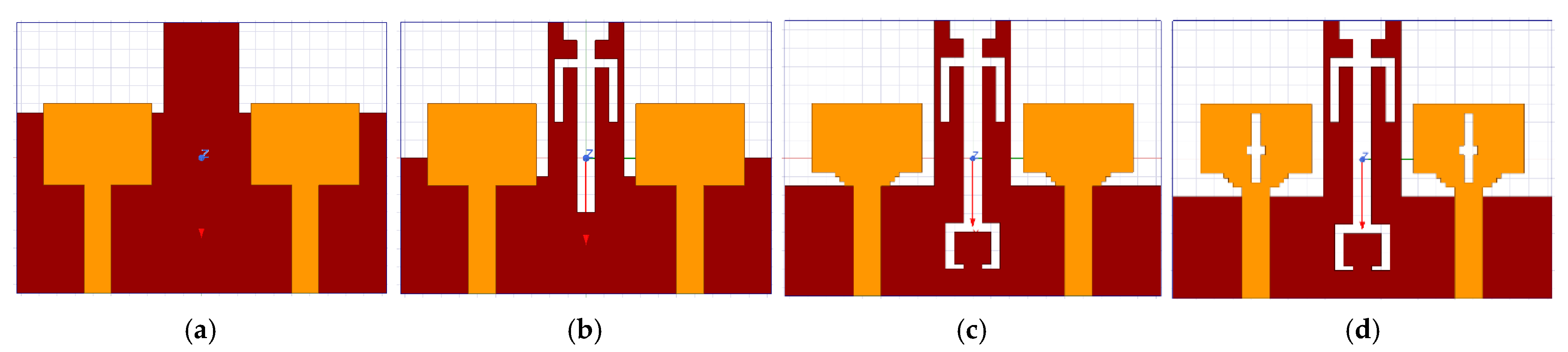
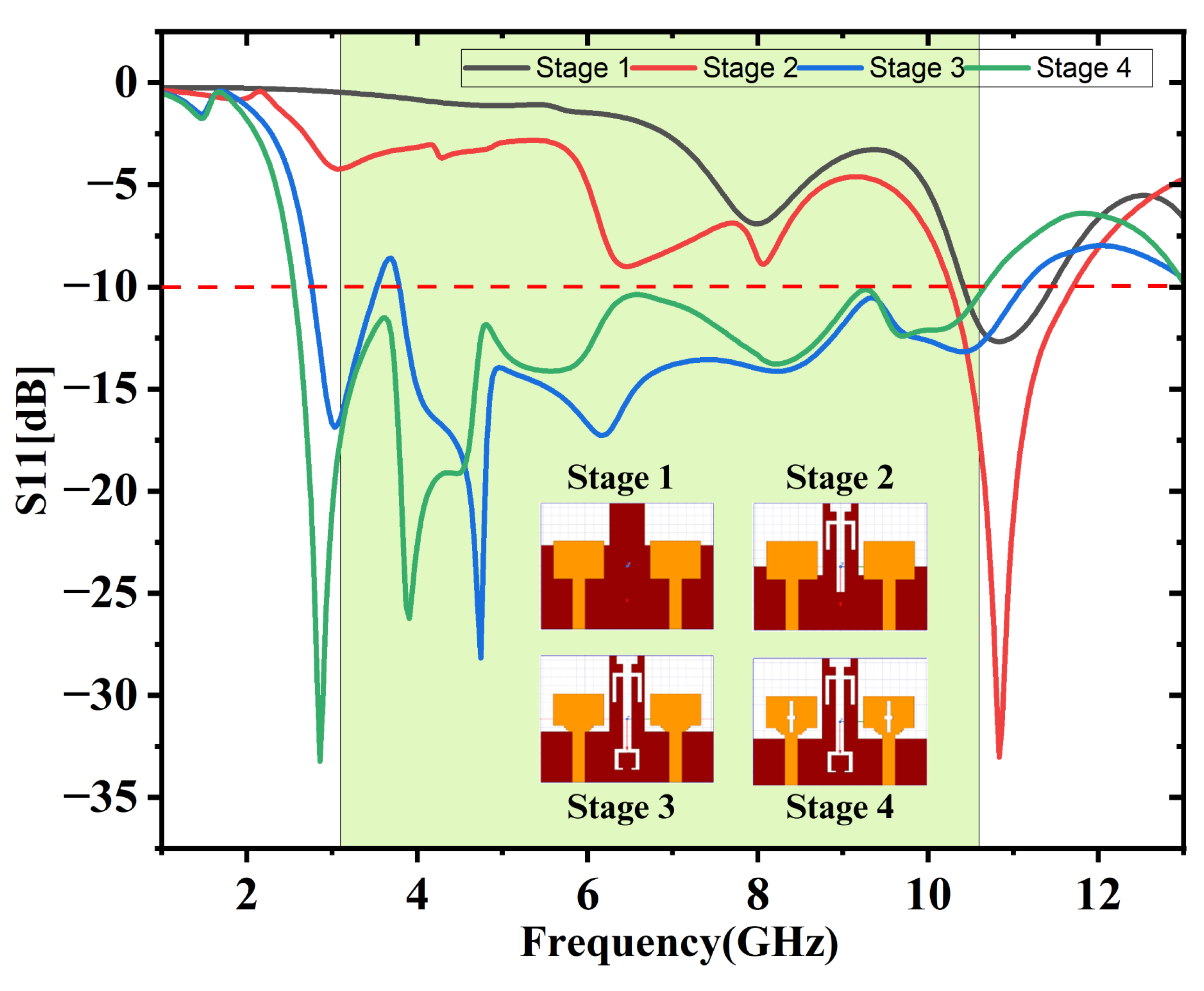
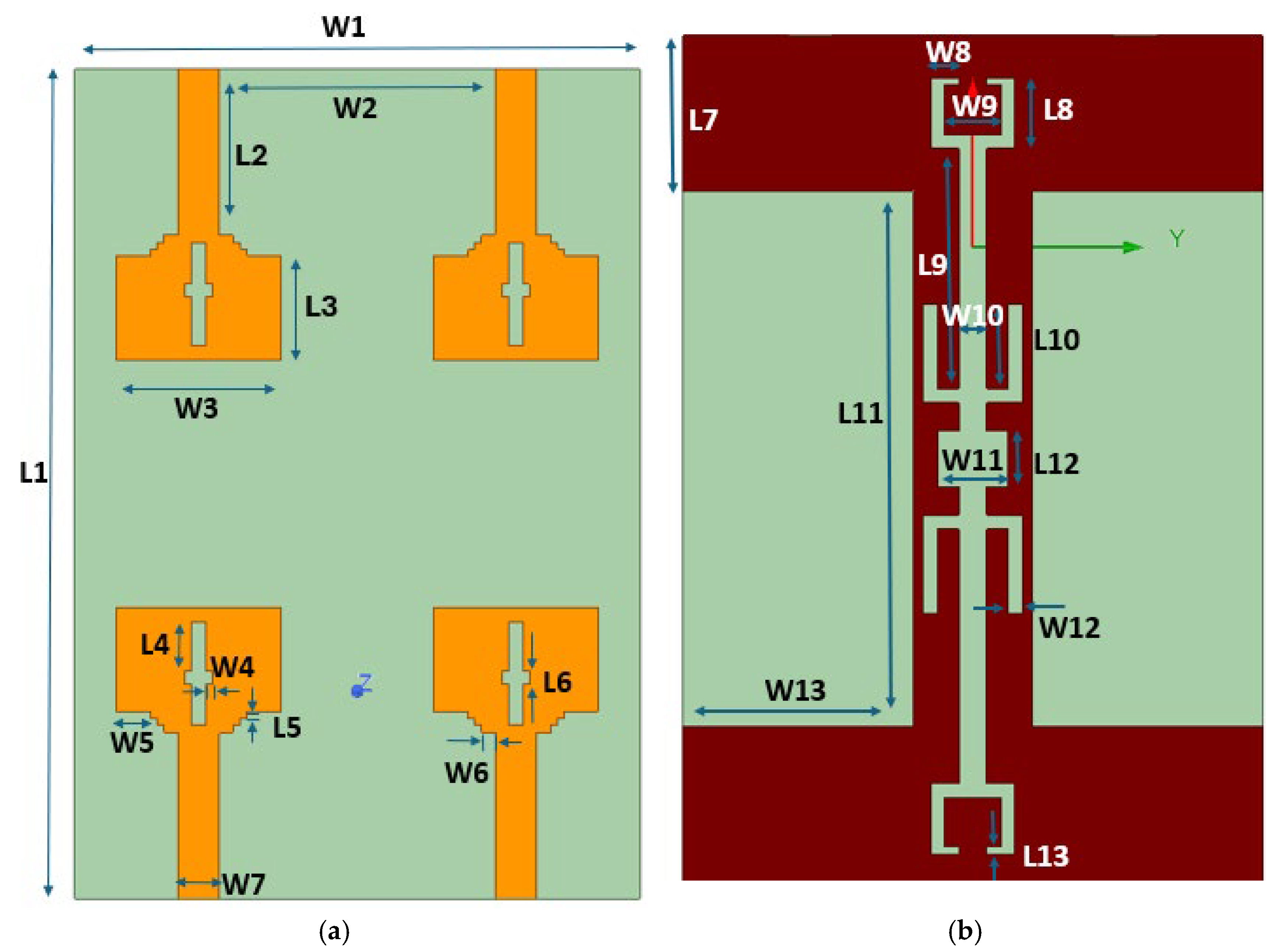
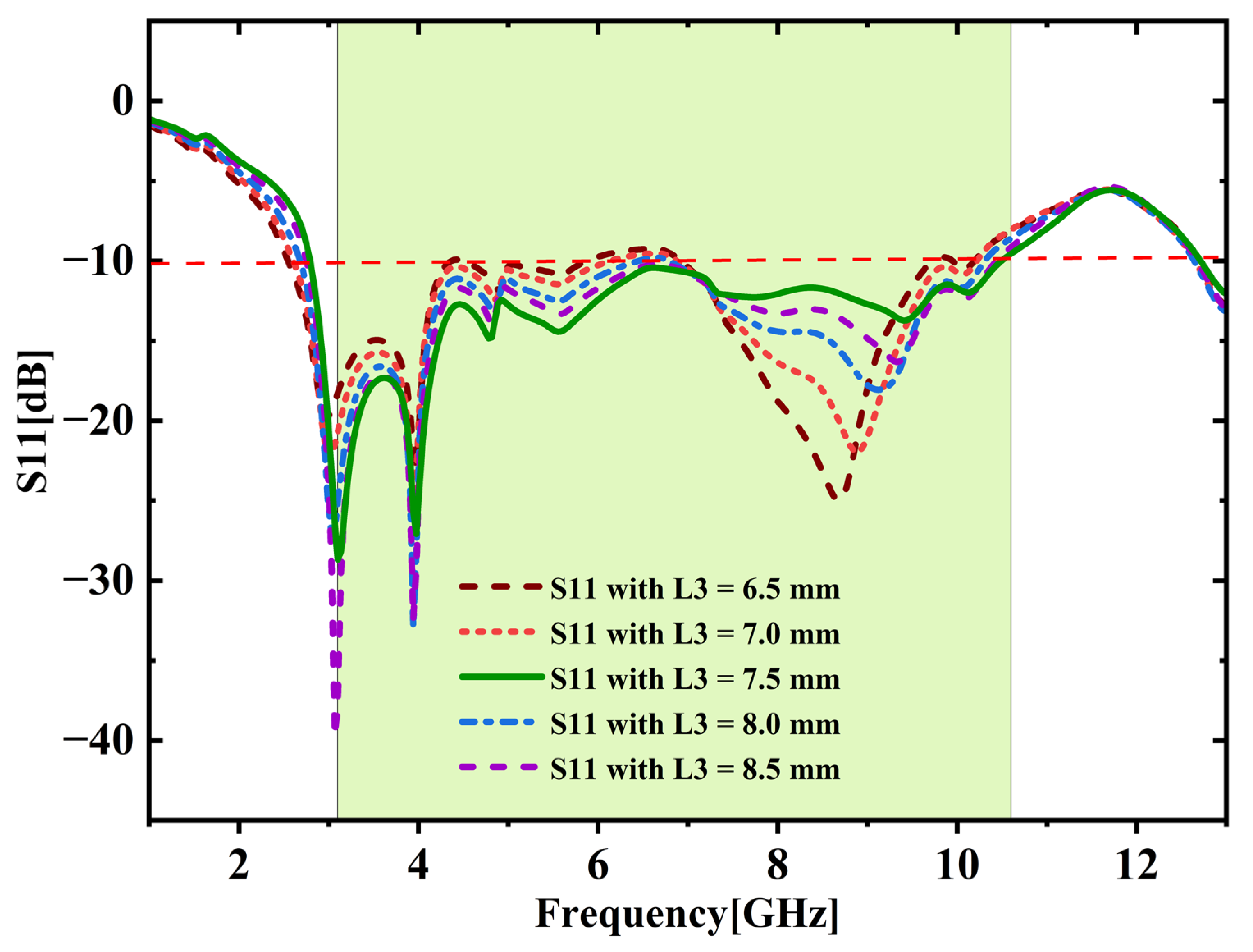
2.1. Geometry and Design Evolution

This section presents the comprehensive geometry and design progression of the presented dual-port MIMO variant. Figure 1a displays the top view and Figure 1b displays the ground view with dimensions 41 × 30 × 1.6 mm3. Table 1 provides a detailed breakdown of the antenna’s dimensions.
This finalized antenna design was achieved through a four-stage development process with parametric analysis. The sequential evolution of the antenna across these four stages is illustrated in Figure 2a–d. The antenna elements are excited by 50 Ω microstrip lines. Stage 1 involves the creation of a basic rectangular radiating element accompanied by a slightly modified ground which is illustrated in Figure 2a. Computed impedance profile is illustrated in Figure 3, revealing that the 10 dB bandwidth achieved fails to encompass the full UWB range spanning 3.1 GHz to 10.6 GHz. At this stage, the electric field is mainly confined near the feed point and the central area of the radiating patch with minimal spreading of surface currents resulting in narrow bandwidth. In Stage 2, a U-shaped slot oriented up-side down and a linear I-shaped slot are embedded into the ground, as illustrated in Figure 2b. This variation leads to a notable improvement in the impedance bandwidth, as evidenced in the simulation results displayed in Figure 3. The current flow on the ground plane was disturbed by the introduction of slots, creating new resonance paths, enabling a broader distribution of the electric field, and helping to enhance the antenna’s bandwidth. However, the desired full UWB range is still not achieved. In Stage 3, two small rectangular notches resembling staircase-like cuts are added to the bottom corners of the radiating patch along with a slot of C-shape which is carved into the antenna’s ground. The updated impedance characteristics are shown in Figure 3 indicating further enhancement in bandwidth. These alterations improve impedance matching by altering current paths and enabling more efficient E-field radiation near the patch edges and the ground slot, though the complete UWB range remains uncovered. Finally in Stage 4, two additional rectangular slots are introduced at the center of the antenna elements, one oriented vertically and the other horizontally so that they intersect to form a cross-shaped slot.
This structure significantly alters the electric-field distribution by enabling stronger coupling between modes and introducing multi-resonant behavior and helps to flatten the reflection coefficient curve and extend the bandwidth. Using the stage 4 structure, a parametric study was conducted by altering the length W1 varied between 10 mm and 14 mm with 1 mm intervals to examine its effect on impedance matching and resonant frequencies. The comparative results for the different values of W1 are illustrated in Figure 4. The analysis reveals that adjusting the W1 length leads to a noticeable increase in bandwidth and a reduction in reflection. Notably, when W1 = 12 mm, the design achieves the widest bandwidth along with the lowest reflection coefficient. This final modification combined with parametric analysis allows the antenna design to effectively cover the full Ultra-Wideband (UWB) spectrum. Figure 5 shows the fabricated prototype equipped with 50-ohm SMA connectors.

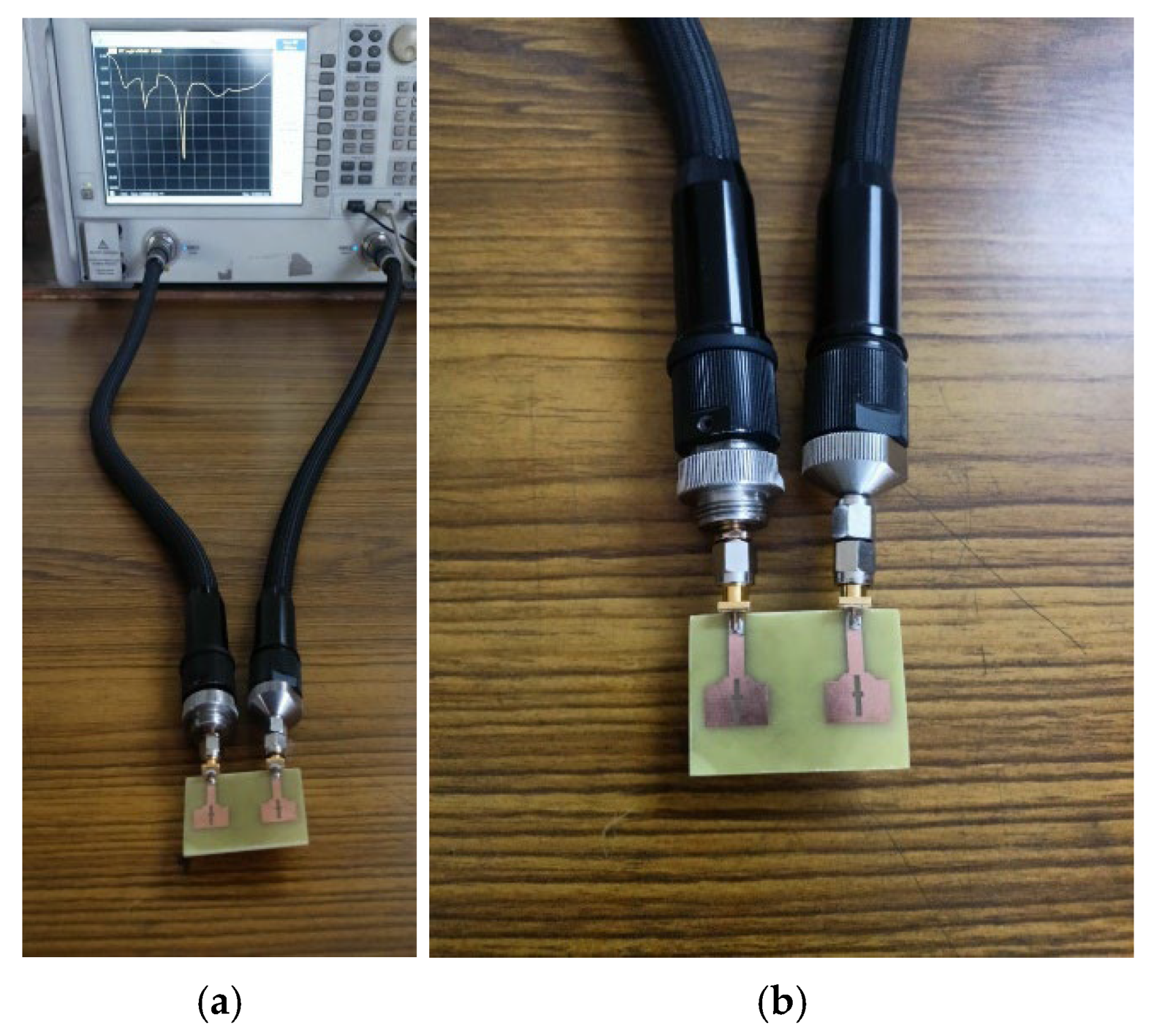
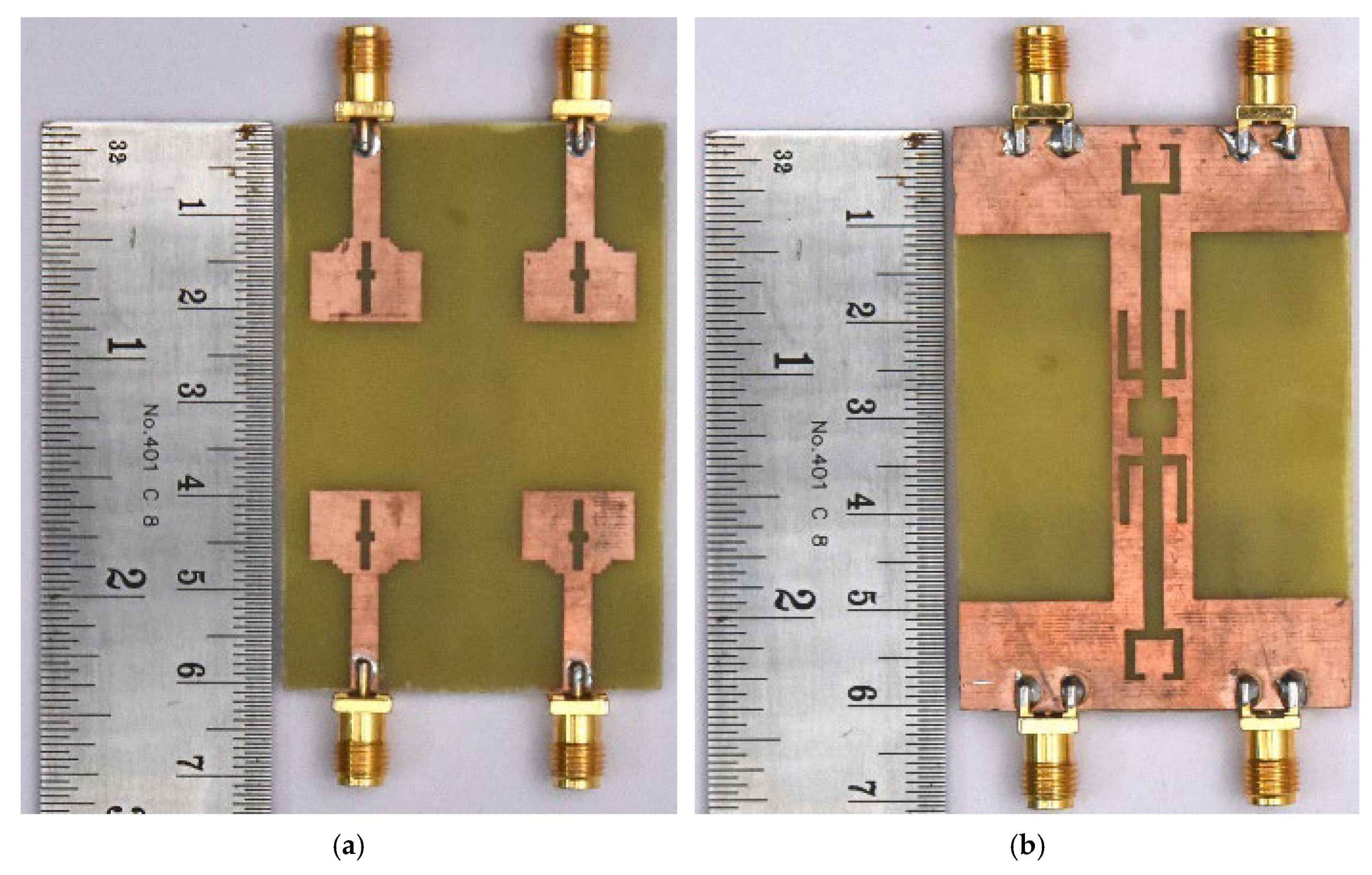
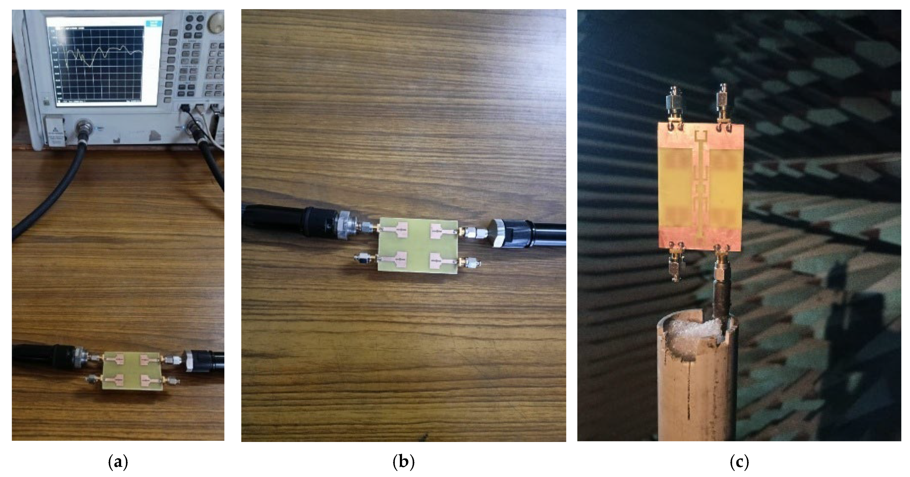
2.2. Antenna Measurements

The testing setup employed for measuring the impedance and radiation performance is illustrated in Figure 6 and Figure 7. The impedance characteristics (SXX and SXY; X and Y values are from 1 to 2) are measured using Agilent N5247A: A.09.90.02 Vector network Analyzer (VNA) illustrated in Figure 6. To measure SXX (reflection) parameter, port X of the fabricated antenna is linked to port 1 of the VNA for signal excitation, and other ports are connected with 50-ohm terminations. For SXY (transmission) parameter measurement ports X and Y of the fabricated antenna are connected to ports 1 and 2 of the VNA.

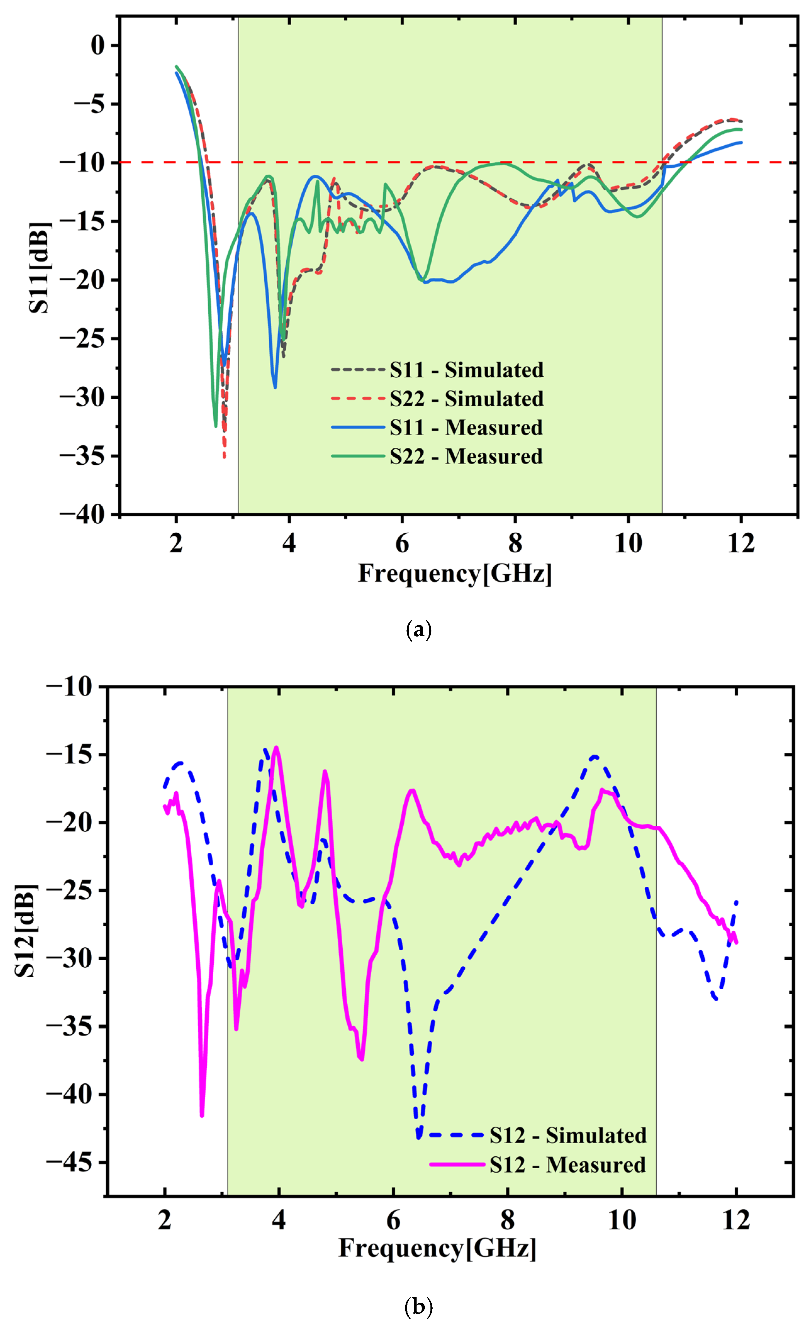
2.3. Validation of S-Parameters: Simulation vs. Measurement (SXX and SXY)
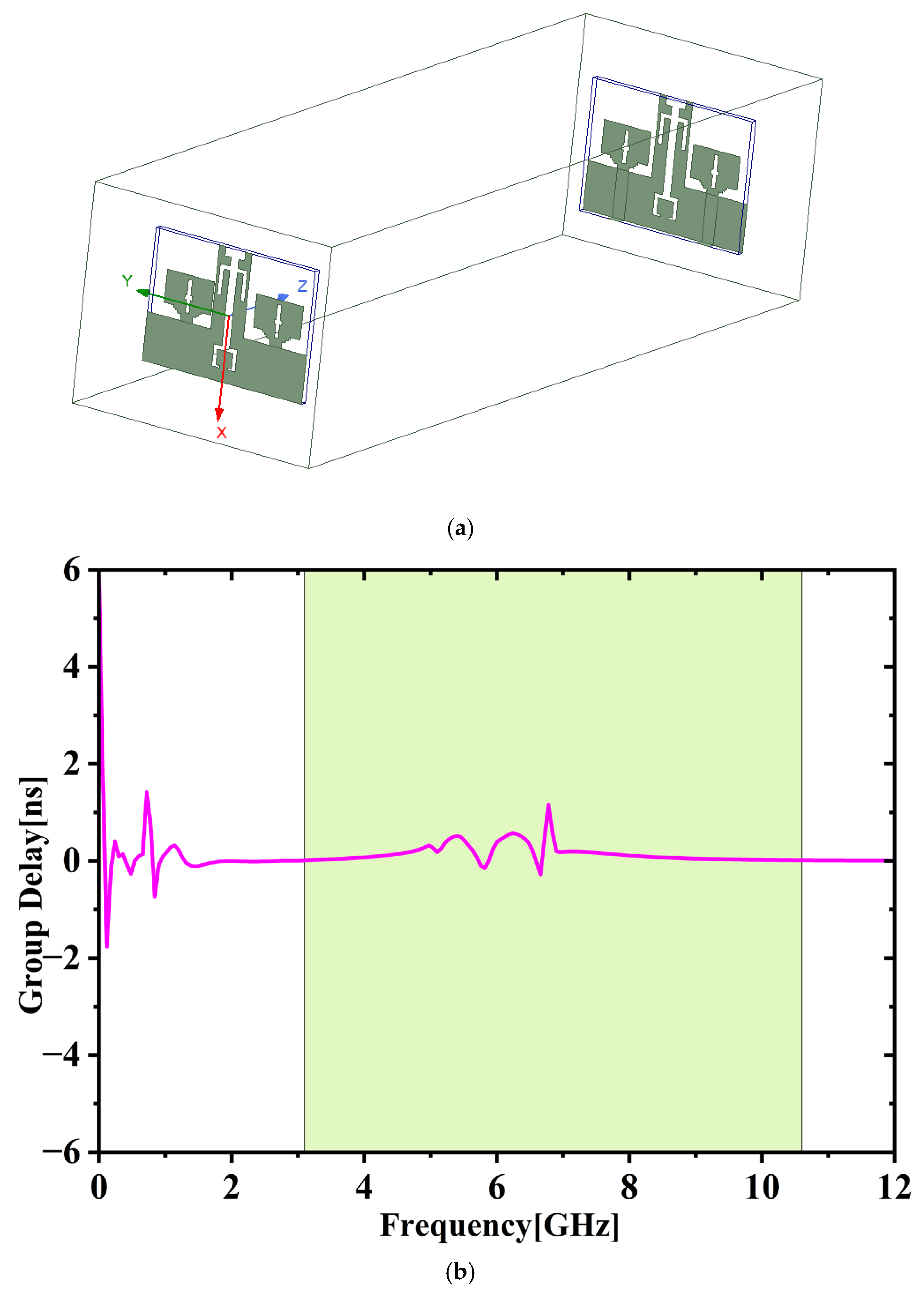
Figure 8a illustrates the relation between the measured and simulated SXX parameters. This plot provides a comparative visualization of simulated and experimentally measured S-parameters, allowing for an assessment of their agreement or deviation. The measured SXX values closely match the simulated data, demonstrating fair agreement. The developed 2-port MIMO antenna supports a broad operating bandwidth spanning 2.6 GHz to 10.8 GHz, based on the SXX < −10 dB threshold. Figure 8b displays the comparison of transmission coefficients (SXY). The data show that SXY remains below −20 dB at higher frequencies and under −15 dB at lower frequencies, confirming that the 2-port MIMO antenna maintains excellent isolation characteristics. Minor variations in the measured results in both cases may arise from factors such as challenges associated with SMA connectors, manufacturing precision limits, and the relatively narrow ground plane set against the connected cable may affect the current flow pattern [24].

2.4. Group Delay

Group delay serves as a key parameter in evaluating the performance of wideband antennas, as it reflects the extent to which a signal waveform is altered during transmission. Figure 9a,b depict the experimental setup for the transmit-receive antenna arrangement and group delay performance. To guarantee far-field measurement conditions, the receiving antenna is positioned 50 cm away, with the far-field distance determined using Equation (1), where ‘B’ represents the separation between the transmit and receive antennas, and ‘S’ denotes the largest dimension of the presented antenna. Figure 9b illustrates the group delay remains uniform throughout the full UWB spectrum.
B = 2 S 2 λ
The delay variation stays within 0.25 ns, indicating that the transmitted signal experiences very little distortion across the operating range.

2.5. Diversity Parameters

2.5.1. Envelope Correlation Coefficient (ECC)

ECC quantifies the level of correlation between signals and indicates possible performance degradation caused by mutual coupling. Equation (2) calculates ECC using scattering (S) parameters between different antenna ports [25,26]. A smaller ECC value signifies improved isolation and superior diversity performance.
ECC = | S i i * S i j + S j i * S j j | 1 | S i i | 2 | S j i | 2 ( 1 | S j j | 2 | S i j | 2 )
Figure 10 compares simulated and measured ECC. It shows ECC remains under 0.01 throughout the intended 3.1 to 10.6 GHz band. The total average ECC across all ports is calculated to be 0.002045, which is notably less than the widely accepted threshold of 0.5, indicating excellent diversity performance [25,26].

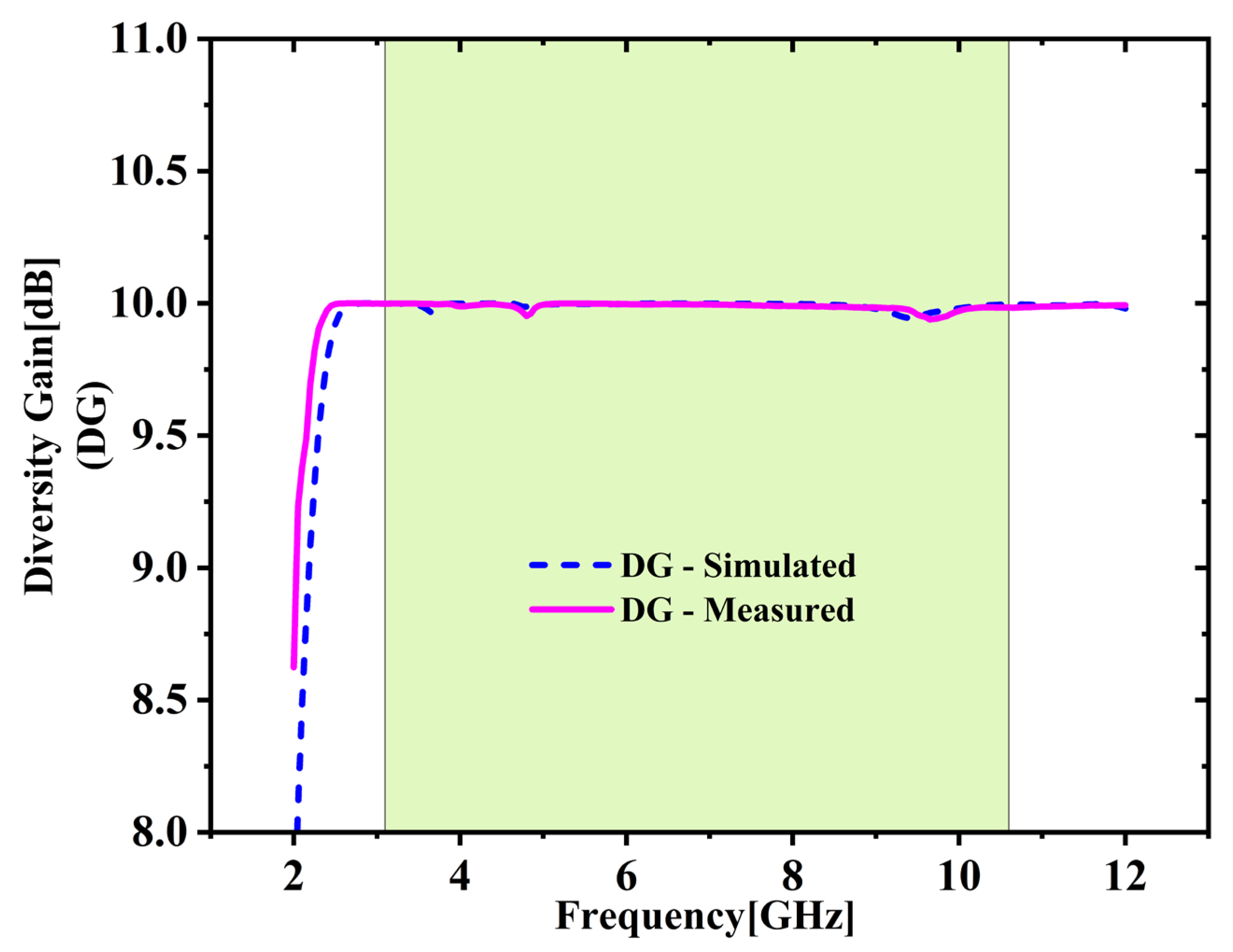
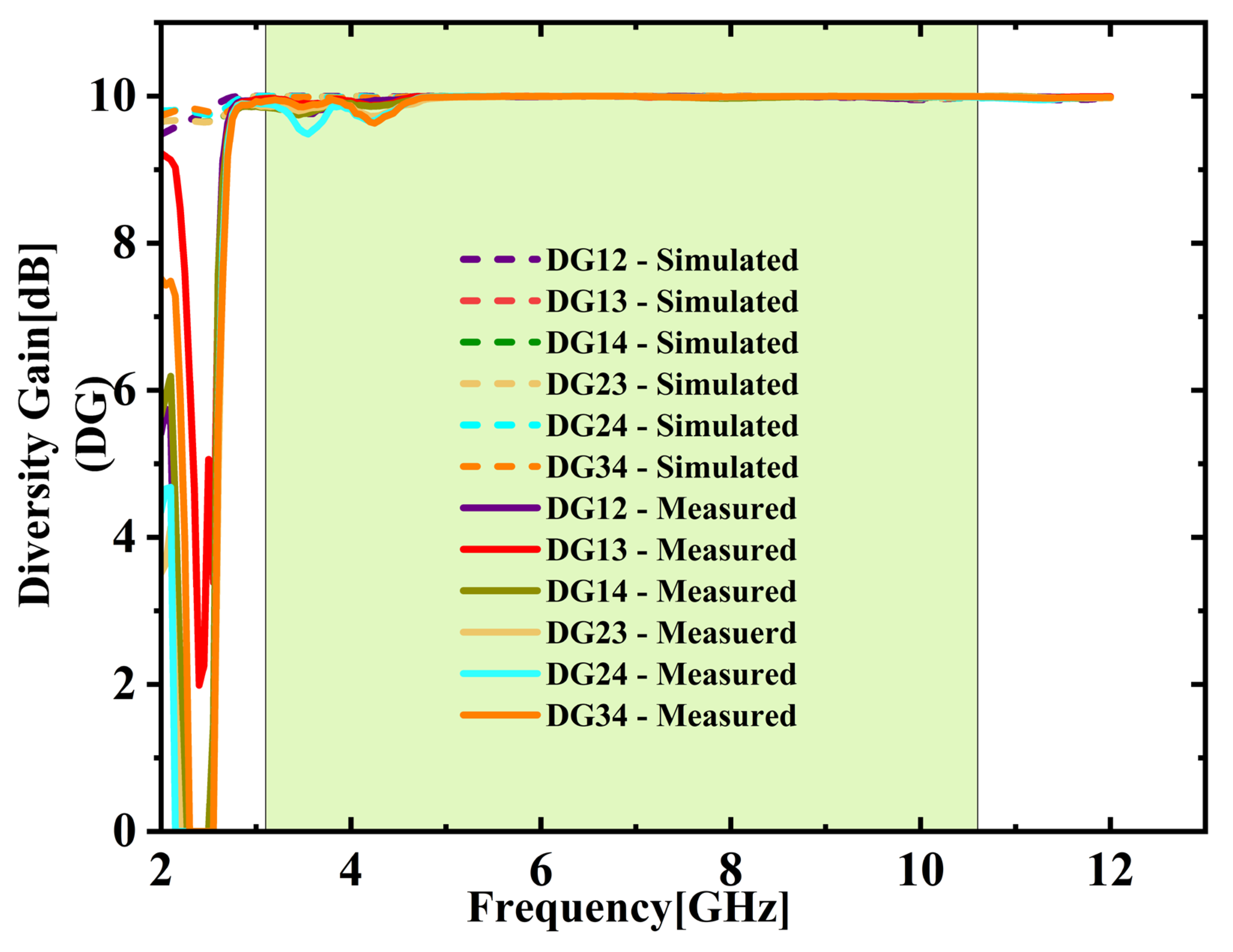
2.5.2. Diversity Gain (DG)

It measures the enhancement in reception achieved through antenna diversity. It is calculated using Equation (3) [25,26], which relies on the characteristics of ECC. Figure 11 demonstrates that both the simulated and measured DG values remain consistently near the ideal benchmark of 10 dB throughout the full UWB spectrum. In this case, the lowest observed DG is 9.93 dB, and the highest is 9.99 dB, resulting in an average DG of 9.98 dB. Hence the system effectively improves signal quality by utilizing multiple antennas.
DG = 10 1 ( E C C ) 2
Low ECC values along with high diversity gain demonstrate strong isolation between the antenna elements. This outcome is the result of spatial separation and a well-optimized ground plane structure. These design features limit electromagnetic interaction and suppress surface current coupling.

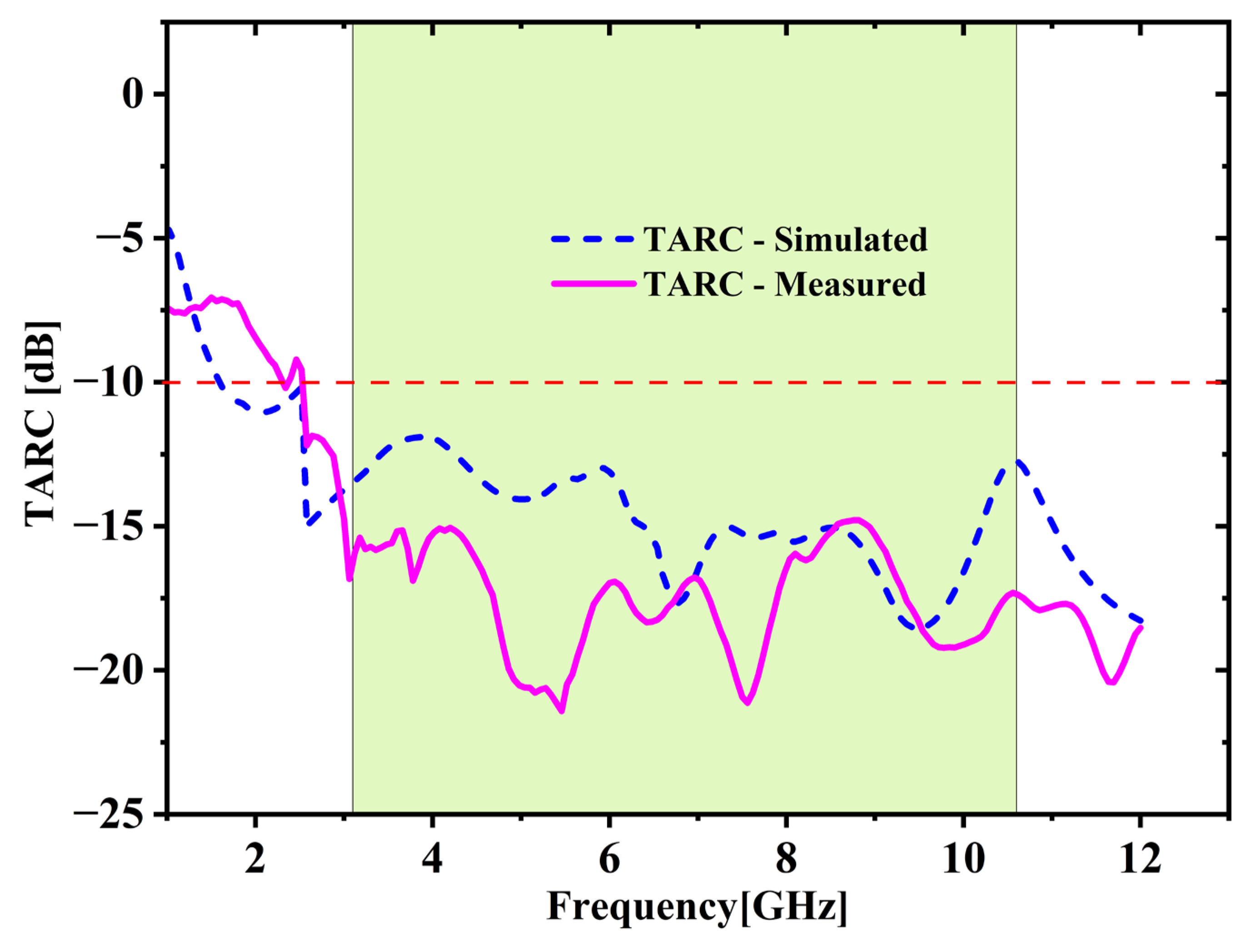
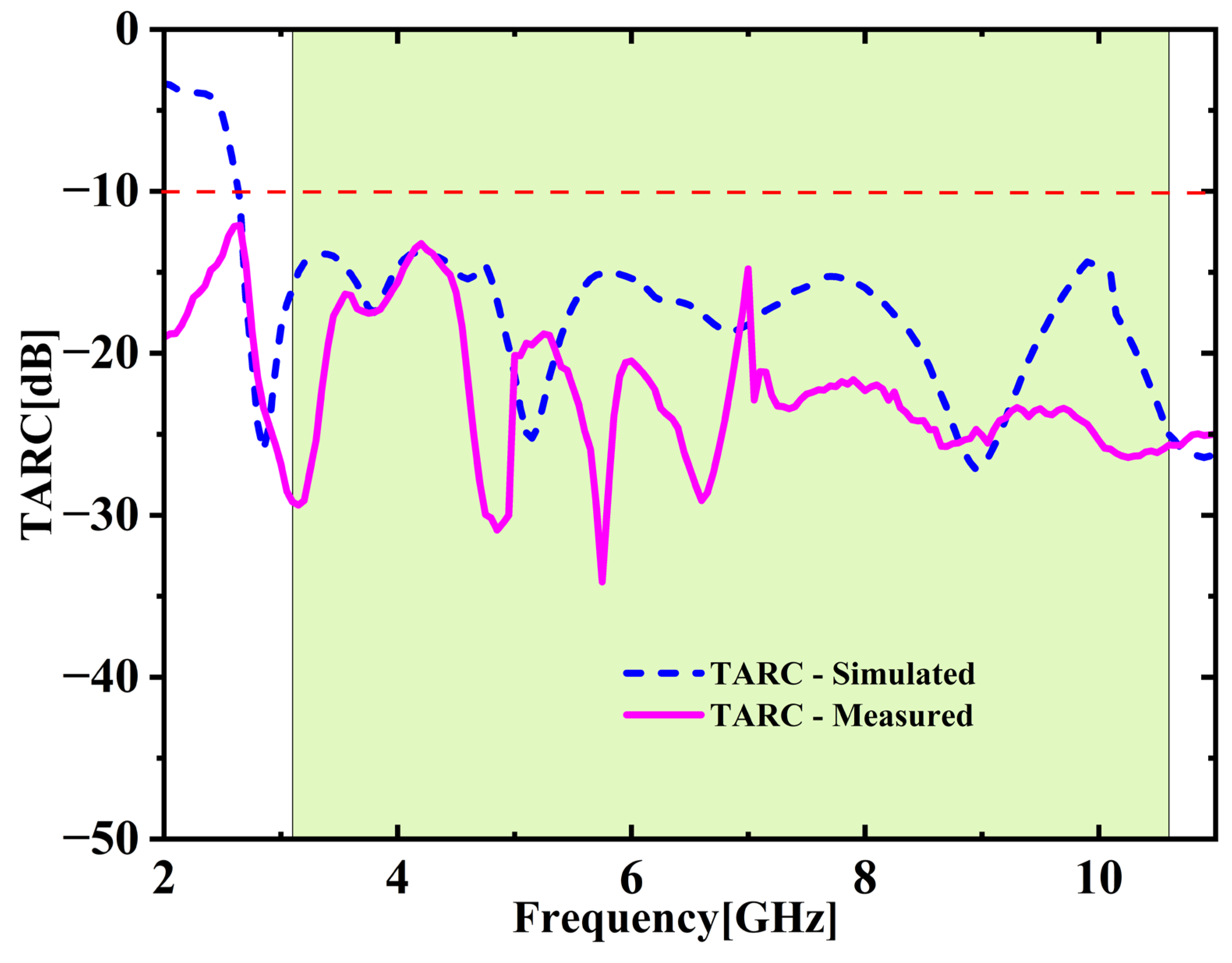
2.5.3. Total Active Reflection Coefficient (TARC)

It evaluates the complete power reflected when all ports are excited simultaneously with identical amplitude and phase. For the developed 2-port MIMO configuration, TARC is determined through Equation (4) [25,26]. Figure 12 illustrates the TARC outcomes obtained from both simulation and measurement. The TARC remains under −10 dB within UWB spectrum for both cases, indicating superior diversity performance of the developed antenna.
TARC = 1 N i = 1 N | j = 1 N S i j | 2

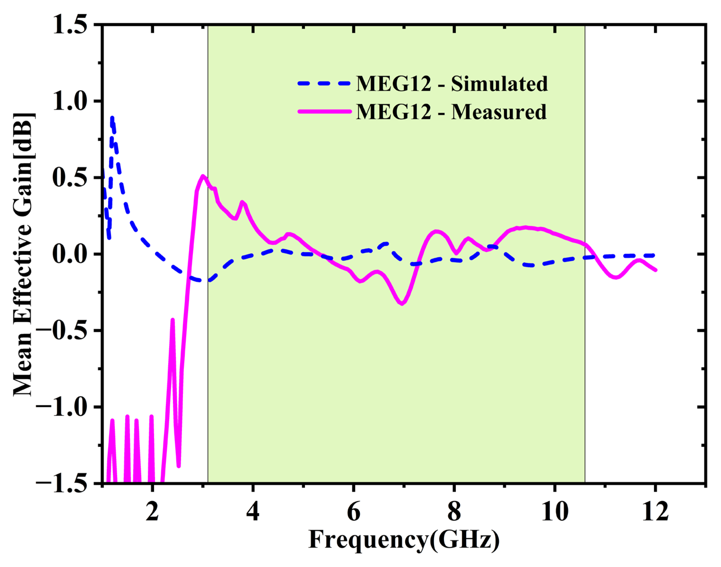
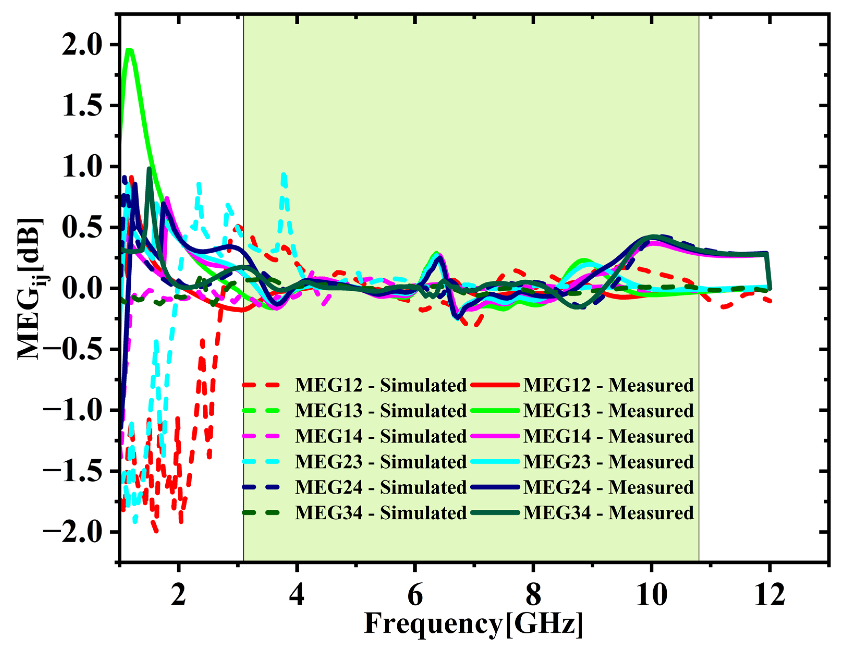
2.5.4. Mean Effective Gain (MEG)

An important parameter for assessing efficiency of individual elements within a MIMO system, especially in practical multipath conditions. It is calculated using Equation (5) [27]. For consistent and balanced diversity performance, the MEG difference between antenna elements should remain within 3 dB [27]. The difference computed with Equation (6) [27] shown in Figure 13, remains under 0.3 dB throughout the UWB frequency range, indicating that the antenna operates consistently and is well balanced.
M E G i = 0.5 [ 1 j = 1 N | S i j | 2 ]
M E G i j = M E G i M E G j

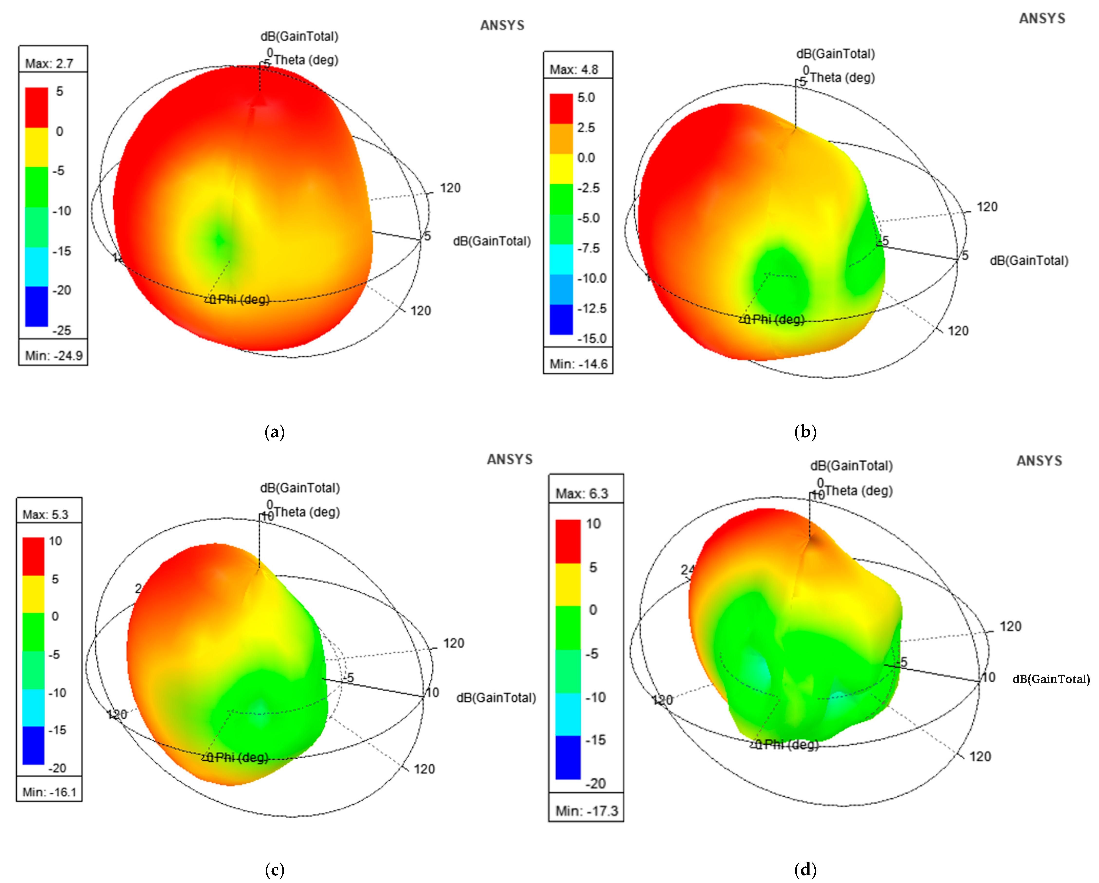
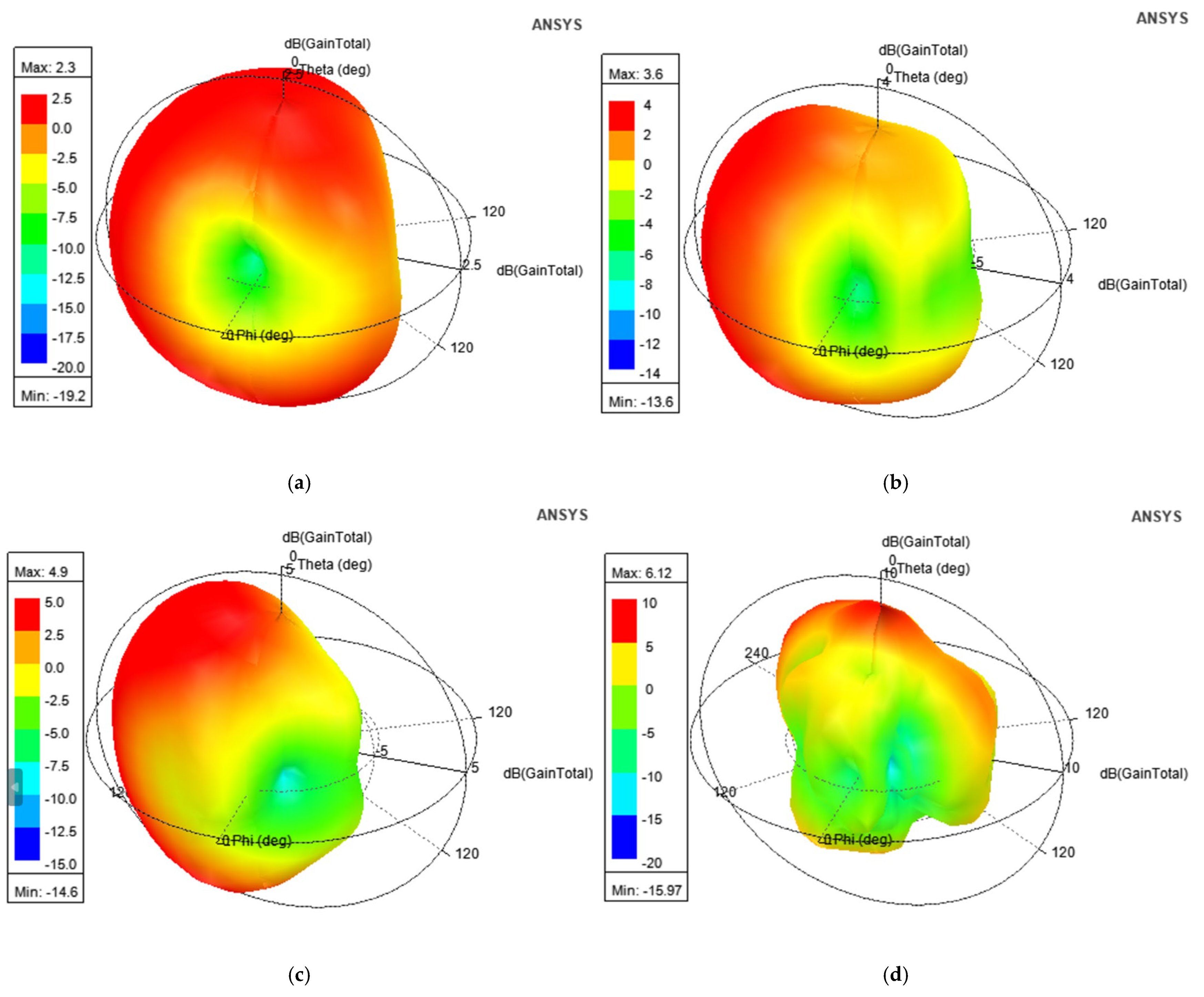
2.6. Radiation Pattern

Figure 14a–d display the 3D radiation patterns pertaining to 4, 6.125, 9.185, and 10.5 GHz. The plots indicate nearly omnidirectional radiation with the gain ranging from 2.7 dB to a peak of 6.3 dB.
A comprehensive comparison between the reported designs and the presented UWB MIMO antenna with emphasis on diversity metrics, bandwidth, and gain is presented in Table 2. Additionally, the computed diversity parameters of the presented UWB antenna are summarized in Table 3.

3. Quad-Port MIMO Antenna

3.1. Antenna Geometry and Design Evolution

This section elaborates a structured and comprehensive analysis of the design methodology and performance assessment of the presented quad-port MIMO variant. The optimized dual-element configuration in the previous section is extended orthogonally in a symmetrical manner to realize a compact 4—element MIMO structure. Figure 15 shows the complete structure. The final dimensions are 60 × 41 × 1.6 mm3. A 50-ohm feedline is used to power each element. A parametric study was performed by varying the parameter ‘L3’ between 6.5 mm and 8.5 mm with increments of 0.5 mm. The results are illustrated in Figure 16. Among those tested values, L3 = 7.5 mm yielded the broadest bandwidth of 8.2 (2.6 GHz to 10.8 GHz). The finalized design dimensions are populated in Table 4. Figure 17 depicts the fabricated 4-port MIMO antenna prototypes equipped with 50-ohm SMA connectors.

3.2. Antenna Measurements

The testing setup employed to evaluate the impedance and radiation characteristics is shown in Figure 18a–c. The impedance parameters (SXX and SXY, where X and Y range from 1 to 4) are recorded using Vector Network Analyzer, as depicted in Figure 18. For SXX (reflection) measurements, port X of the fabricated antenna is connected with the first port VNA while the others are connected with 50-ohm terminations. For SXY (transmission) measurements, the antenna’s X and Y ports are connected with ports 1 and 2 of the VNA, respectively.

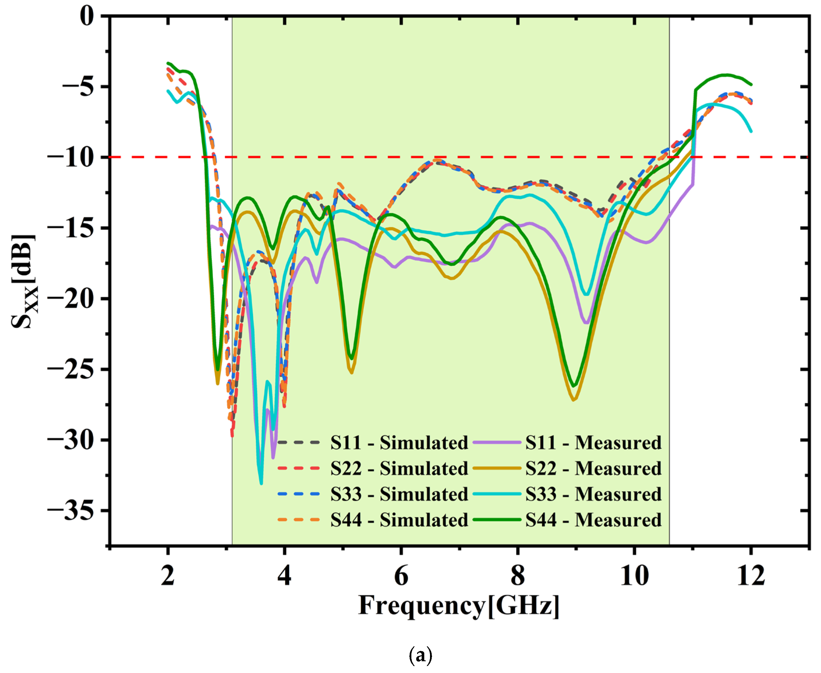
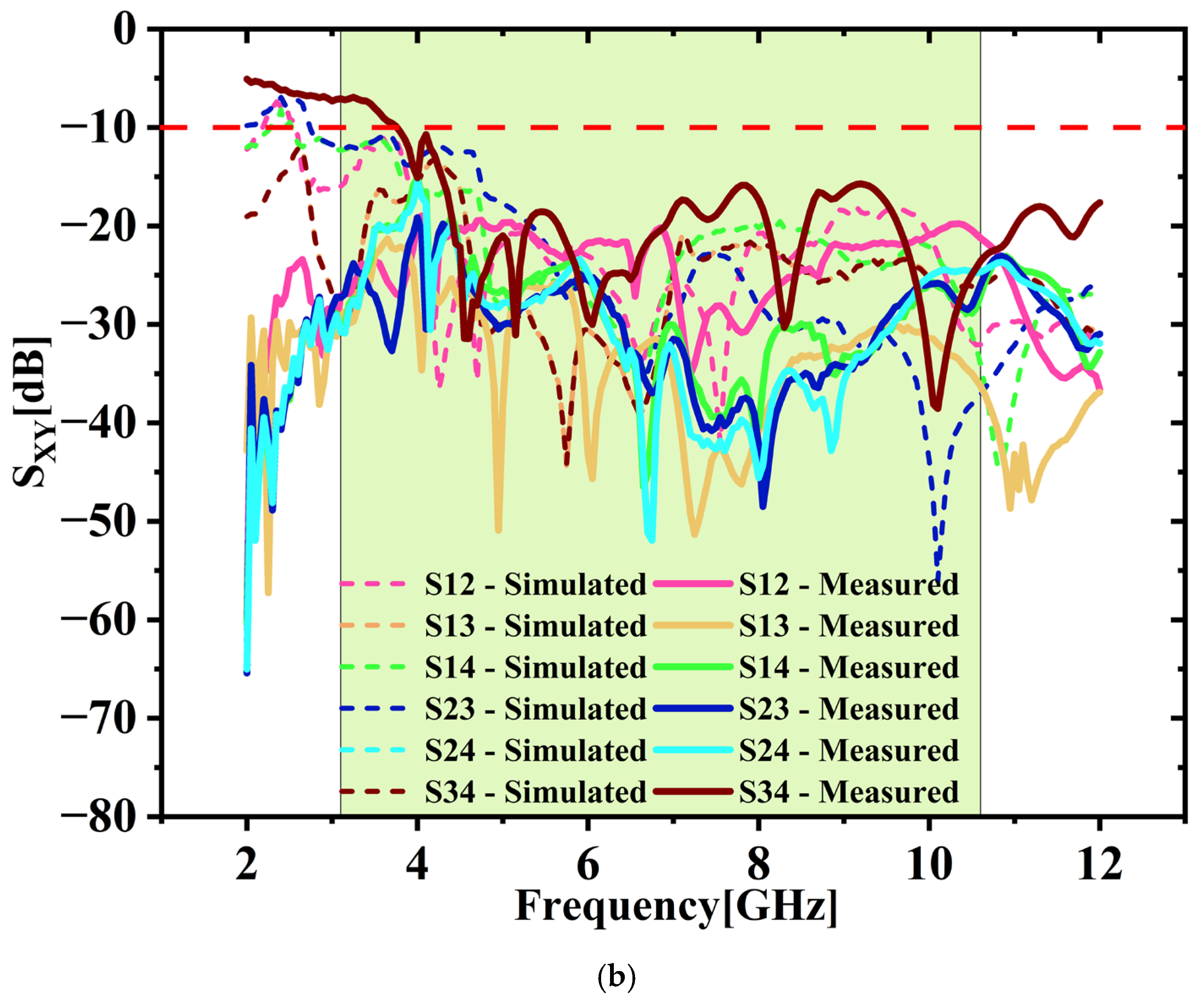
3.3. Validation of S-Parameters: Simulation vs. Measurement (SXX and SXY)

Figure 19a,b compare SXX and SXY parameters both simulated and measured. Measured results closely match the simulations, demonstrating strong agreement. The fabricated antenna clearly achieves a bandwidth of 8.2 GHz (with SXX < −10 dB) along with excellent isolation (SXY < −15 dB) throughout UWB range.

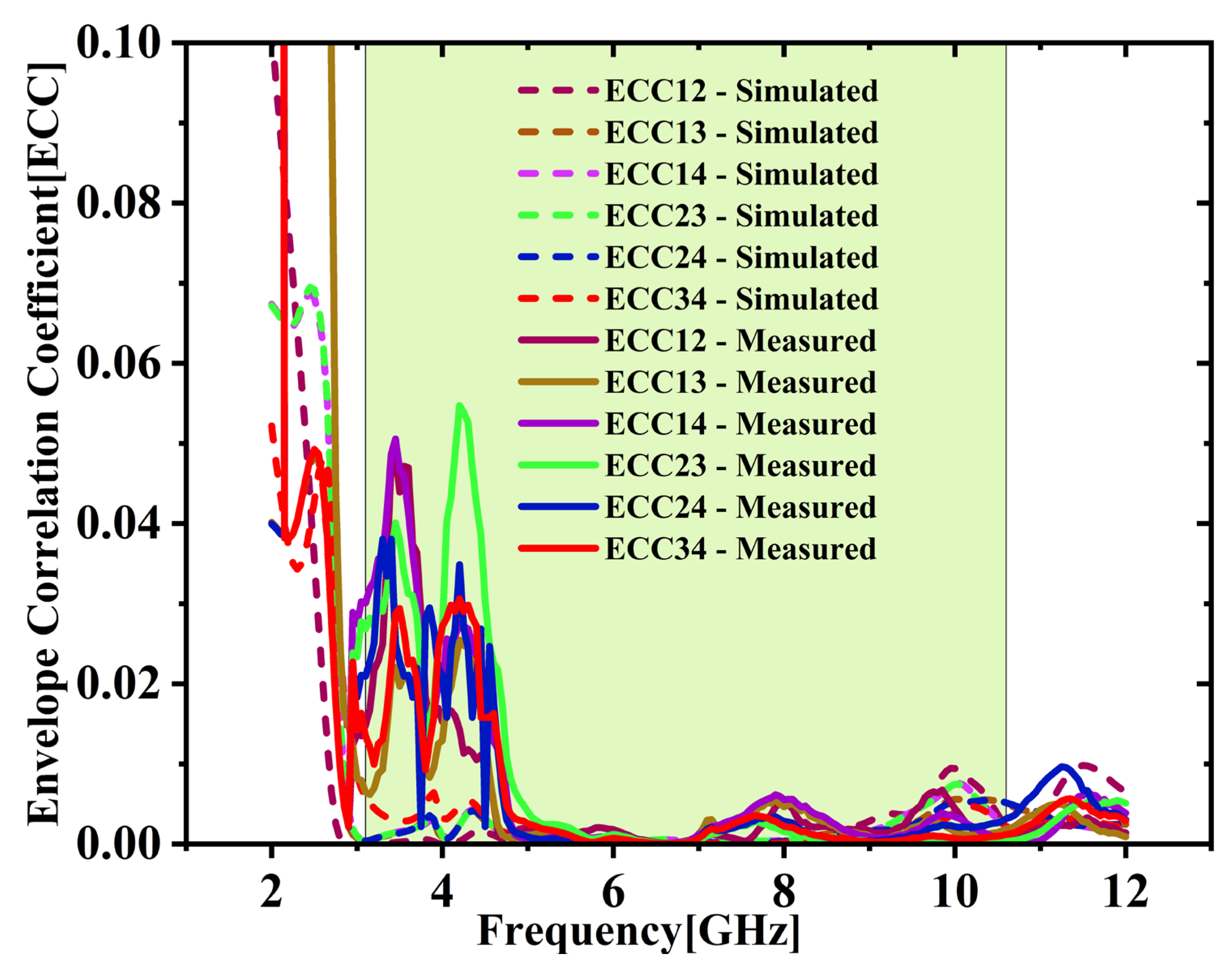
3.4. Diversity Analysis: ECC, DG, TARC and MEG

The ECC between various port combinations is derived with the S-parameters utilizing Equation (2) [25,26]. As depicted in Figure 20, both simulation and experimental results indicate that ECC remains under 0.05 throughout the UWB spectrum. Average ECC is 0.01432, which is far below the 0.5 limit, indicating excellent diversity. Figure 21 shows the DG values stay close to the optimal 10 dB across the full UWB band. The DG ranges from 9.31 to 9.99 dB with an average of 9.65 dB across the desired UWB band. This confirms effective signal enhancement using multiple antenna elements. TARC is evaluated based on Equation (4) [25,26]. Figure 22 presents both simulated and measured outcomes, each indicating a TARC is under −10 dB. This validates the antenna’s effective diversity performance. The MEG and MEG difference between the antenna elements of the proposed design are computed with the help of Equations (5) and (6) [27]. For balanced diversity, the MEG difference should be within 3 dB. As shown in Figure 23, the calculated difference stays below 0.3 dB across the UWB band. This confirms the antenna’s stable and well-balanced performance.

3.5. Radiation Pattern

Figure 24a–d display the 3D radiation patterns pertaining to 4, 6.125, 9.185, and 10.5 GHz. The plots indicate nearly omnidirectional radiation with a gain ranging from 2.3 dB to a peak of 6.12 dB.
A comprehensive comparison between the existing designs and the presented antenna with emphasis on diversity metrics, bandwidth, and gain is presented in Table 5. Additionally, the computed diversity parameters of the presented UWB antenna across different frequencies are listed in Table 6.

4. Conclusions

Compact dual-port and quad-port MIMO antennas have been developed to enhance overall efficiency of 5G Midband (n77/n78/n79/n96/n102) and UWB communication systems, offering improved diversity and better isolation. Both designs provide a broad impedance bandwidth of 8.2 GHz, spanning 2.6 GHz to 10.8 GHz, with reflection coefficient (SXX) consistently below –10 dB across the band. Both configurations demonstrate excellent strong inter-element isolation, where coupling (Sxy) remains under –15 dB at lower bands and drops beneath –20 dB at elevated frequencies. The MIMO antennas, both two-port and four-port, show excellent performance with low ECC, high Diversity Gain, and minimal MEG difference. TARC remains below the threshold, and signal delay variation is kept under 0.25 ns. These metrics ensure stable and efficient MIMO operation. Overall, the proposed antennas are compact and efficient solutions for 5G mid-band (C-band) and UWB MIMO systems. Future work will scale UWB-MIMO to larger arrays (4 × 4, 8 × 8) using advanced isolation methods (metamaterials, EBG, neutralization lines) and flexible, reconfigurable substrates for wearable and adaptive systems.

Author Contributions

Conceptualization, K.R.; Methodology, K.R.; Software, T.C.; Writing—original draft, K.R.; Writing—review & editing, S.G.; Supervision, S.G. All authors have read and agreed to the published version of the manuscript.

Funding

No external sources of funding were received for this research.

Data Availability Statement

All original findings discussed in this study are contained within the article and any additional questions can be addressed to the corresponding author.

Conflicts of Interest

The authors declare no conflict of interest.

References

  1. Xu, H.; Yang, L. Ultra-wideband technology: Yesterday, today, and tomorrow. In Proceedings of the 2008 IEEE Radio and Wireless Symposium (RWS), Orlando, FL, USA, 22–24 January 2008; pp. 715–718. [Google Scholar] [CrossRef]
  2. Federal Communications Commission. First Report and Order, Section IV-B. UWB Definitions: FCC 02-48: Revisions of Part 15 of the Commission’s Rules Regarding Ultrawideband Transmission Systems; Federal Communications Commission: Washington, DC, USA, 2002.
  3. Tarokh, V.; Naguib, A.F.; Seshadri, N.; Calderbank, A.R. Space-time codes for high data rate wireless communication: Mismatch analysis. IEEE Trans. Inf. Theory 2002, 44, 309–313. [Google Scholar] [CrossRef]
  4. Foschini, G.J. Layered space-time architecture for wireless communication in a fading environment when using multi-element antennas. Bell Labs Tech. J. 1996, 1, 41–59. [Google Scholar] [CrossRef]
  5. Tranter, J.W.; Taylor, D.P.; Ziemer, R.E.; Maxemchuk, N.F.; Mark, J.W. The Best of the Best: Fifty Years of Communications and Networking Research; IEEE Communications Society; IEEE Press: New York, NY, USA, 2007. [Google Scholar]
  6. Foschini, G.; Gans, M. On Limits of Wireless Communications in a Fading Environment when Using Multiple Antennas. Wirel. Pers. Commun. 1998, 6, 311–335. [Google Scholar] [CrossRef]
  7. Azim, R.; Mobashsher, A.; Islam, M.T.; Misran, N. Compact planar antenna for UWB applications. In Proceedings of the 2010 International Conference on Microwave and Millimeter Wave Technology (ICMMT), Chengdu, China, 8–11 May 2010; Volume 43, pp. 1987–1990. [Google Scholar] [CrossRef]
  8. Zhu, S.; Langley, R. Dual-band wearable textile antenna on an EBG substrate. IEEE Trans. Antennas Propag. 2009, 57, 926–935. [Google Scholar] [CrossRef]
  9. Jiang, Y.-T.; Zhang, H.; Xu, H.; Zhang, R.; Zeng, X.-F. A novel ultra-wideband antenna with band notch characteristic. In Proceedings of the 2012 International Conference on Microwave and Millimeter Wave Technology (ICMMT), Shenzhen, China, 5–8 May 2012; pp. 1–4. [Google Scholar] [CrossRef]
  10. Mishra, S.K.; Gupta, R.K.; Vaidya, A.; Mukherjee, J. A Compact Dual-Band Fork-Shaped Monopole Antenna for Bluetooth and UWB Applications. IEEE Antennas Wirel. Propag. Lett. 2011, 10, 627–630. [Google Scholar] [CrossRef]
  11. Sharawi, M.S.; Numan, A.B.; Khan, M.U.; Aloi, D.N. A Dual-Element Dual-Band MIMO Antenna System with Enhanced Isolation for Mobile Terminals. IEEE Antennas Wirel. Propag. Lett. 2012, 11, 1006–1009. [Google Scholar] [CrossRef]
  12. Li, M.; Zhong, B.G.; Cheung, S.W. Isolation Enhancement for MIMO Patch Antennas Using Near-Field Resonators as Coupling-Mode Transducers. IEEE Trans. Antennas Propag. 2019, 67, 755–764. [Google Scholar] [CrossRef]
  13. Kiani, S.H.; Savci, H.S.; Munir, M.E.; Sedik, A.; Mostafa, H. An Ultra-Wide Band MIMO Antenna System with Enhanced Isolation for Microwave Imaging Applications. Micromachines 2023, 14, 1732. [Google Scholar] [CrossRef]
  14. Jabire, A.H.; Podilchak, S.K.; Antar, Y.M.M.; Smolskiy, S. Design of a Compact UWB/MIMO Antenna with High Isolation and Gain. In Proceedings of the 2020 IEEE Microwave Theory and Techniques in Wireless Communications (MTTW), Riga, Latvia, 5–7 October 2020; pp. 72–75. [Google Scholar] [CrossRef]
  15. Wang, L.; Chen, Z.N.; See, T.S.P.; Wu, B.; Yang, Y. Compact UWB MIMO Antenna with High Isolation Using Fence-Type Decoupling Structure. IEEE Antennas Wirel. Propag. Lett. 2019, 18, 1641–1645. [Google Scholar] [CrossRef]
  16. Bahmanzadeh, F.; Mohajeri, F. Simulation and Fabrication of a High-Isolation Very Compact MIMO Antenna for Ultra-Wide Band Applications with Dual Band-Notched Characteristics. AEU-Int. J. Electron. Commun. 2021, 128, 153505. [Google Scholar] [CrossRef]
  17. Babu, K.V.; Anuradha, B. Design of UWB MIMO Antenna to Reduce the Mutual Coupling Using Defected Ground Structure. Wirel. Pers. Commun. 2021, 118, 3469–3484. [Google Scholar] [CrossRef]
  18. Chen, H.N.; Song, J.-M.; Park, J.-D. A Compact Circularly Polarized MIMO Dielectric Resonator Antenna over Electromagnetic Band-Gap Surface for 5G Applications. IEEE Access 2019, 7, 140889–140898. [Google Scholar] [CrossRef]
  19. Du, Z.; Zhang, X.; Qin, P.; Pu, Y.; Xi, X. Introduction of the Orthogonal Mode via the Polarization Conversion Parasitic Structure for the Isolation Enhancement of MIMO Patch Antennas. Int. J. Microw. Wirel. Technol. 2024, 16, 893–901. [Google Scholar] [CrossRef]
  20. Thongbor, P.; Ruengwaree, A.; Pirajnanchai, V.; Naktong, W.; Fhafhiem, N. Rectangular Monopole Antenna with Arrow-Shaped Slot Etching for UWB-MIMO Application. In Proceedings of the 13th International Conference on Electrical Engineering/Electronics, Computer, Telecommunications and Information Technology (ECTI-CON), Chiang Mai, Thailand, 28 June–1 July 2016; pp. 1–4. [Google Scholar] [CrossRef]
  21. Liu, R.; An, X.; Zheng, H.; Wang, M.; Gao, Z.; Li, E. Neutralization Line Decoupling Tri-Band Multiple-Input Multiple-Output Antenna Design. IEEE Access 2020, 8, 27018–27026. [Google Scholar] [CrossRef]
  22. Malviya, L.; Chouhan, S. Multi-Cut Four-Port Shared Radiator with Stepped Ground and Diversity Effects for WLAN Application. Int. J. Microw. Wirel. Technol. 2019, 11, 1044–1053. [Google Scholar] [CrossRef]
  23. Mohanty, A.; Sahu, S. Integration of Coupling Resonator as Port-Isolator and MMLC-Minkowski Fractal Loop for Wi-Max Rejection in 4-Port Compact UWB MIMO Antenna. J. Electromagn. Waves Appl. 2021, 35, 1359–1377. [Google Scholar] [CrossRef]
  24. Chen, Z.N.; See, T.S.P.; Qing, X. Small Printed Ultrawideband Antenna with Reduced Ground Plane Effect. IEEE Trans. Antennas Propag. 2007, 55, 383–388. [Google Scholar] [CrossRef]
  25. Moses, A.T.Z.; Moses, N.; Janapala, D.K. An Electrically Small 4-Port Self-Decoupled MIMO Antenna Pairs Operating in n78 5G NR Band for Smartphone Applications. AEU—Int. J. Electron. Commun. 2022, 145, 154082. [Google Scholar] [CrossRef]
  26. Addepalli, T.; Anitha, V.R. Parametric Analysis of Compact UWB-MIMO Antenna with Improved Isolation Using Parasitic Reflectors and Protruded Ground Strips. Wirel. Pers. Commun. 2022, 123, 2209–2225. [Google Scholar] [CrossRef]
  27. Serghiou, D.; Khalily, M.; Singh, V.; Araghi, A.; Tafazolli, R. Sub-6 GHz Dual-Band 8×8 MIMO Antenna for 5G Smartphones. IEEE Antennas Wirel. Propag. Lett. 2020, 19, 1546–1550. [Google Scholar] [CrossRef]
  28. Kapure, V.R.; Rathod, S.S. A Two-Element EBG-Inspired UWB MIMO Antenna with Triple Band Notched Characteristics and High Isolation. Sādhanā 2023, 48, 7. [Google Scholar] [CrossRef]
  29. Khalil, M.I.; Elkamchouchi, H.M.; Elhennawy, H.M. A Flower-Shaped Miniaturized UWB-MIMO Antenna with High Isolation. Electronics 2022, 11, 2190. [Google Scholar] [CrossRef]
  30. Agarwal, M.; Dhanoa, J.K.; Khandelwal, M.K. Ultrawide Band Two-Port MIMO Diversity Antenna with Triple Notch Bands, Stable Gain and Suppressed Mutual Coupling. AEU Int. J. Electron. Commun. 2020, 120, 153225. [Google Scholar] [CrossRef]
  31. Kumari, T.; Das, G.; Sharma, A.; Gangwar, R.K. Design Approach for Dual Element Hybrid MIMO Antenna Arrangement for Wideband Applications. Int. J. RF Microw. Comput.-Aided Eng. 2019, 29, e21486. [Google Scholar] [CrossRef]
  32. Kumar, A.; Ansari, A.Q.; Kanaujia, B.K.; Kishor, J.; Tewari, N. Design of Triple-Band MIMO Antenna with One Band-Notched Characteristic. Prog. Electromagn. Res. C 2018, 86, 41–53. [Google Scholar] [CrossRef]
  33. Bhatti, R.A.; Choi, J.-H.; Park, S.-O. Quad-Band MIMO Antenna Array for Portable Wireless Communications Terminals. IEEE Antennas Wirel. Propag. Lett. 2009, 8, 129–132. [Google Scholar] [CrossRef]
  34. Ghosh, P.; Gorai, A.; Behera, S.; Ghatak, R. Design of Compact UWB Antenna Using Characteristic Mode Analysis and Its Quad-Port MIMO Realization with Novel Isolation Technique. J. Electromagn. Waves Appl. 2024, 38, 443–459. [Google Scholar] [CrossRef]
  35. Ahmad, S.; Ullah, U.; Khan, M.J.; Ali, A.; Alibakhshikenari, M.; See, C.H.; Abd-Alhameed, R.A. A Compact CPW-Fed Ultra-Wideband Multi-Input-Multi-Output (MIMO) Antenna for Wireless Communication Networks. IEEE Access 2022, 10, 25278–25289. [Google Scholar] [CrossRef]
  36. Wu, A.; Zhao, M.; Zhang, P.; Zhang, Z. A Compact Four-Port MIMO Antenna for UWB Applications. Sensors 2022, 22, 5788. [Google Scholar] [CrossRef]
  37. Rekha, V.S.D.; Pardhasaradhi, P.; Madhav, B.T.P.; Devi, Y.U. Dual Band Notched Orthogonal 4-Element MIMO Antenna with Isolation for UWB Applications. IEEE Access 2020, 8, 145871–145880. [Google Scholar] [CrossRef]
  38. Raheja, D.K.; Kanaujia, B.K.; Kumar, S. Compact Four-Port MIMO Antenna on Slotted-Edge Substrate with Dual-Band Rejection Characteristics. Int. J. RF Microw. Comput.-Aided Eng. 2019, 29, e21756. [Google Scholar] [CrossRef]
  39. Kayabasi, A.; Toktas, A.; Yigit, E.; Sabanci, K. Triangular Quad-Port Multi-Polarized UWB MIMO Antenna with Enhanced Isolation Using Neutralization Ring. AEU—Int. J. Electron. Commun. 2018, 85, 47–53. [Google Scholar] [CrossRef]
  40. Kiem, N.K.; Phuong, H.N.B.; Chien, D.N. Design of Compact 4 × 4 UWB-MIMO Antenna with WLAN Band Rejection. Int. J. Antennas Propag. 2014, 2014, 539094. [Google Scholar] [CrossRef]
Figure 1. Dual-port geometry (a) top layout (b) ground layout.
Micromachines 16 00716 g001
Figure 2. (ad) Stage-wise advancement in the proposed antenna configuration.
Micromachines 16 00716 g002
Figure 3. Simulated S11 vs. frequency for four-stage antenna evolution.
Micromachines 16 00716 g003
Figure 4. Parametric analysis (W1 = 12 mm to 16 mm).
Micromachines 16 00716 g004
Figure 5. Fabricated antenna (a) top view (b) ground view.
Micromachines 16 00716 g005
Figure 6. (a) Impedance characteristics measurement setup with Agilent N5247A: A.09.90.02 VNA and (b) closer view of fabricated antenna with VNA connectors.
Micromachines 16 00716 g006
Figure 7. Radiation characteristics measurement setup using anechoic chamber.
Micromachines 16 00716 g007
Figure 8. (a) SXX vs. frequency (b) SXY vs. frequency.
Micromachines 16 00716 g008
Figure 9. (a) Antenna arrangement for group delay measurement. (b) Group delay vs. frequency.
Micromachines 16 00716 g009
Figure 10. Comparison of simulated and measured ECC.
Micromachines 16 00716 g010
Figure 11. Diversity gain (DG) comparison.
Micromachines 16 00716 g011
Figure 12. Total active reflection coefficient (TARC) comparison.
Micromachines 16 00716 g012
Figure 13. Simulated vs. measured MEG comparison.
Micromachines 16 00716 g013
Figure 14. Three-dimensional (3D) radiation patterns at (a) 4.0 GHz; (b) 6.125 GHz; (c) 9.185 GHz; (d) 10.5 GHz.
Micromachines 16 00716 g014
Figure 15. Quad-port geometry (a) top layout (b) ground layout.
Micromachines 16 00716 g015
Figure 16. Parametric analysis (L3 = 6.5 mm to 8.5 mm).
Micromachines 16 00716 g016
Figure 17. Fabricated prototype (a) top view and (b) ground view.
Micromachines 16 00716 g017
Figure 18. (a) Measurement setup for Impedance characteristics. (b) Closer view of fabricated antenna with VNA connectors. (c) Radiation characteristics measurement setup using anechoic chamber.
Micromachines 16 00716 g018
Figure 19. (a) SXX vs. frequency (b) SXY vs. frequency.
Micromachines 16 00716 g019aMicromachines 16 00716 g019b
Figure 20. Simulated vs. measured ECC comparison.
Micromachines 16 00716 g020
Figure 21. Directive gain (DG) comparison.
Micromachines 16 00716 g021
Figure 22. Total active reflection coefficient (TARC) comparison.
Micromachines 16 00716 g022
Figure 23. Simulated vs. measured MEG comparison.
Micromachines 16 00716 g023
Figure 24. Three-dimensional (3D) radiation patterns at (a) 4.0 GHz; (b) 6.125 GHz; (c) 9.185 GHz; (d) 10.5 GHz.
Micromachines 16 00716 g024
Table 1. Proposed 2-port antenna dimension details.
ParametersMeasurement (mm)ParametersMeasurement (mm)ParametersMeasurement (mm)
L30L1017W51
L17.5L1119W63
L23.5L125W75
L31L1311W81.5
L43L140.5W91
L50.5W41W104
L612W112W1112
L72W21W121
L82W30.5W132
L97W42.5
Table 2. Comparison of antenna characteristics: proposed design vs. existing literature.
Ref No/Published YearSize
(mm3)
UWB Bandwidth
(GHz)
Isolation
(dB)
ECCDG
(dB)
TARC
(dB)
MEG
(dB)
Peak Gain
(dBi)
No. of Ports
[28]/202347 × 38 × 0.82.9–11.0200.0039.99 <0≈14.12
[29]/202230 × 18 × 1.64.3–15.6320<0.0079.96NR *NR5.32
[30]/202038.5 × 38.5 × 1.63.0–11.0250.0479.8NRNR6.02
[31]/201959 × 55 × 8.13.0–7.018<0.219.64NRNR42
[32]/201850 × 30 × 1.63.0–16.016<0.01NR<0≈13.02
[33]/200950 × 100 × 1.62.0–6.015<0.019.6NR≈16.02
P.A. 130 × 41 × 1.62.6–10.820<0.0079.96<−100.36.32
* NR—Not Reported; 1 P.A.—Proposed Antenna.
Table 3. Assessment of performance metrics at various frequencies based on S-parameter analysis.
Diversity ParametersSelected Frequencies (GHz)
4578910
ECC0.002340.000960.00080.002030.003180.00582
TARC [dB]−11.957−14.048−16.337−15.537−16.449−16.462
MEG [dB]0.18720.04518−0.31000.00500.12600.13069
DG [dB]9.988279.995199.995589.989839.984119.97085
Table 4. Proposed antenna dimension details.
ParametersMeasurement (mm)ParametersMeasurement (mm)ParametersMeasurement (mm)
L160L106W61
L212L1138W73
L37.5L124W82
L43L130.5W94
L50.5W141W102
L61W240W115
L711W312W121
L85W40.5W1316
L917W52.5
Table 5. Comparison of antenna characteristics: proposed design vs. existing literature.
Ref No/Published YearSize
(mm3)
UWB
Bandwidth
(GHz)
Isolation
(dB)
ECCDG
(dB)
TARC
(dB)
MEG
(dB)
Gain
(dBi)
No. of Ports
[34]/202440 × 40 × 1.62.51–1816<0.1≈10NR *NR3.54
[35]/202260 × 60 × 1.63.0–11.020<0.029.98<−10NR3.44
[36]/202245 × 45 × 1.63.1–13.117<0.029.9985<−25NR44
[37]/202080 × 80 × 1.62.1–2025<0.029.99NRNR5.84
[38]/201958 × 58 × 1.63.0–13.522<0.008≈10NRNR2.94
[39]/201875.19 × 75.19 × 1.63.1–17.313<0.1NRNRNR5.54
[40]/201460 × 60 × 1.62.7–10.615<0.063NRNRNR3.54
P.A. 160 × 41 × 1.62.6–10.815<0.059.65<−100.36.124
* NR—Not Reported 1 P.A.—Proposed Antenna.
Table 6. Assessment of performance metrics at various frequencies based on S-parameter analysis.
Diversity ParametersSelected Frequencies (GHz)
4578910
ECC120.000020.000740.000170.000060.002860.00942
TARC [dB]−14.697−21.360−18.238−15.949−27.040−14.773
MEG12 [dB]0.18720.0451−0.31000.02760.12600.1306
DG12 [dB]9.99989.996269.99919.99969.98579.9528
Disclaimer/Publisher’s Note: The statements, opinions and data contained in all publications are solely those of the individual author(s) and contributor(s) and not of MDPI and/or the editor(s). MDPI and/or the editor(s) disclaim responsibility for any injury to people or property resulting from any ideas, methods, instructions or products referred to in the content.

