1. Introduction
During the past years, the transition to 5G as well as ongoing research towards telecommunication systems beyond current standards have indicated a pressing need for new and efficient devices. In particular, the transition from radio and microwave to mm-wave frequencies requires devices that operate at higher frequencies to provide larger bandwidths. Consequently, mm-wave devices possess finer structures that pose challenges to the fabrication processes. Thus, to facilitate the fabrication of novel waveguiding designs in the mm-wave spectrum, the substrate-integrated waveguide (SIW) structure has been proposed [
1,
2]. An SIW consists of two parallel dense series of metallic vias into metallic-covered substrate, which, in turn, enables wave propagation in the channel created by the vias–metallic cover system. This concept has been further utilised in various designs, like frequency filters [
3], couplers [
4], or power dividers [
5]. Furthermore, the SIW concept was expanded for antenna applications through the substrate-integrated cavity (SIC) design [
6,
7]. An SIC works as a cavity resonator antenna composed of a closed SIW design, fed with a coaxial cable at the bottom and with an aperture on top [
8,
9,
10,
11]. Many interesting features arise with this design at the mm-wave frequencies, including easier fabrication on dielectric substrates, while enabling an easier attachment of advanced materials on the radiative slot.
Another concept that has recently gained the attention of researchers and engineers is that of time-varying materials [
12,
13,
14,
15,
16]. Time-varying materials are artificial media characterised by rapid changes in their electromagnetic properties while a slower-paced phenomenon takes place. Time-varying artificial media or surfaces hold promise for the engineering of various novel and advanced devices, outperforming common ones that are stationary in time for different spectra, from microwaves to optics. Applications include, among others, parametric amplifiers [
17,
18,
19], frequency shifters [
20,
21], anti-reflective surfaces [
22], and reconfigurable, beam-forming metasurfaces [
23,
24]. A particular feature of periodically modulated time-varying media is the incitement of harmonic frequencies, which could be very interesting for designing new sources for the next generation of telecommunications in the mm-wave spectrum. In this context, graphene is a perfect candidate for the time-varying platform in the mm-wave and the THz spectrum, because its surface conductivity can be effectively and rapidly modulated using an externally applied electric bias field. Due to its impressive characteristics, this 2D material has been theoretically analysed and utilised in its time-varying form for frequency harmonic generation beyond the far-infrared regime [
25,
26,
27,
28]. Consequently, the exploitation of the inherent time-varying capabilities of graphene can be combined with a conventional radiator, such as the cavity antenna, to produce a frequency generator device in a straightforward manner.
In this paper, we combine the concepts of the SIC radiator and the time-varying graphene to propose a non-linear antenna design, capable of generating and radiating frequencies in the mm-wave spectrum. In particular, the inherent ability of graphene modulation via an external bias is integrated with a well-established antenna, providing a realistic source for modern telecommunications. Initially, we describe graphene with a dispersive surface conductivity following the Drude model. Afterwards, we introduce the time modulation of the surface conductivity by alternating the real-time bias electric field imposed on graphene. Then, we utilise an efficient and accurate modified finite-difference time-domain (FDTD) algorithm to numerically simulate the time-varying surface conductivity via the concept of the equivalent surface current. Initially, the theoretical case of an infinite time-varying graphene sheet is simulated to examine the scattering effects for a harmonic periodic modulation and gain insight into the planar material’s behaviour. Following the theoretical analysis, we optimally design an SIC to operate approximately at 60 GHz, while we draw a suitable graphene-loaded slot aperture on its upper side to enable radiation. The developed numerical algorithm is now employed to investigate the time-varying aspects of the proposed non-linear antenna. Numerical results prove the reasonable higher-order harmonic generation, while different types of periodic modulation schemes are applied to enhance a certain set of desired harmonics. As a consequence, this analysis certifies the potential of our design for future non-linear antennas and frequency generators for the mm-wave and THz regimes.
2. Theoretical Formulation
2.1. Graphene’s Surface Conductivity
In our work, graphene is considered as a thin layer, characterised by its surface conductivity
. The latter depends on the chemical potential
, controlled by an external bias electric field
, the scattering rate
, related to the main loss mechanism, and the temperature
T. The surface conductivity is evaluated by the compact expression resulting from the Kubo formula [
29], involving only the intraband term, which is the dominant term in the mm-wave spectrum, as follows:
with
as the frequency-independent term,
as the electron charge, and
ħ,
the reduced Planck and Boltzmann constants, respectively. We can observe in (
1) that the surface conductivity of graphene follows the Drude dispersion model. As mentioned above, the chemical potential is connected with the applied electrostatic bias field,
, by the following:
where
is the Fermi velocity, while
follows the Fermi–Dirac distribution, or
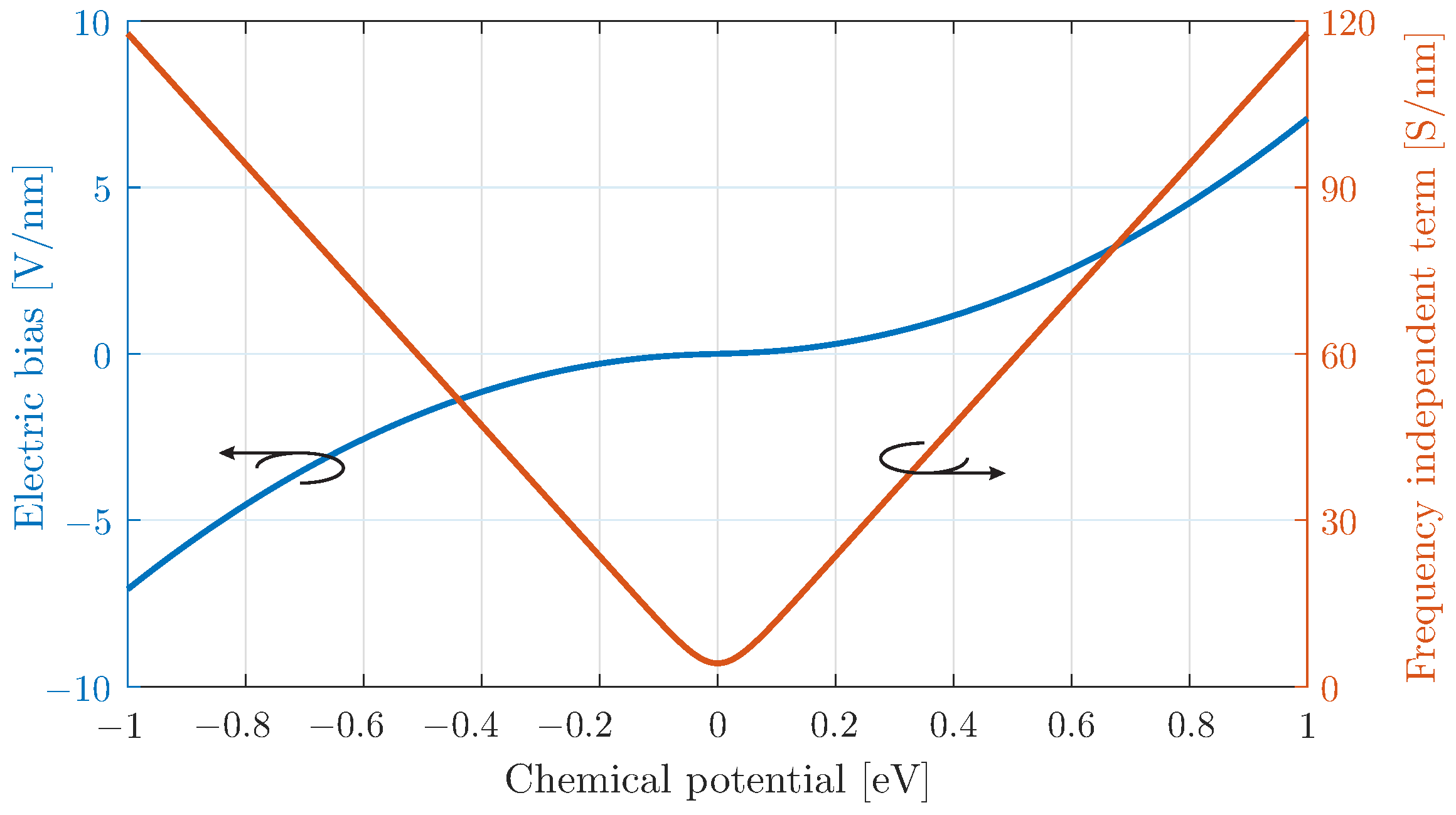
The relation between the chemical potential with its bias field is depicted in
Figure 1, indicating a strongly non-linear response near bias field values close to zero. This is more evident in the relation of the chemical potential with the frequency-independent term
of the surface conductivity. Here, a linear approximation is valid for
> 0.1 eV. In practice, the modulation scheme can be applied on the external bias field
. This will result in a dynamic alteration of the chemical potential
, evaluated through (
2) and the frequency-independent term
of the surface conductivity in (
1). This procedure is able to realistically account for the non-linearities of chemical potential near the zero values of the applied bias field. Note that the graphene surface conductivity in (
1) has a low-pass filter response, which can potentially degrade the stimulation of higher frequencies. Nevertheless, the cut-off frequency, defined by the scattering rate
, is beyond 10 THz, while our analysis is focused at the much lower mm-wave regime.
In this context, the temporal modulation of graphene is realistically applied as
where
is a constant bias, and
is the time-varying component of the bias. In this paper, we investigate the following three distinct cases of periodic temporal variations, with
denoting the modulation frequency:
, namely a harmonic variation, where is the modulation depth, characterising the strength of the modulation;
, where is the sign function, representing a square wave or periodic pulse modulation;
, representing a harmonic modulation without a constant bias, namely around the minimum surface conductivity.
The first type of time modulations is the same that was used in previous modelling attempts for time-varying and dispersive media [
17,
26,
30,
31]. Similarly, the numerator of the dispersion equation, Drude [
26] or Lorentz [
31], was harmonically modulated in the same way as the first type above. In this work, we further expand this analysis scheme by examining more modulation types in dispersive media and by applying the findings on non-linear graphene antenna structures.
2.2. FDTD Modelling of Graphene as a Surface Conductivity
The analysis throughout this work is conducted numerically via an accurate FDTD method, since its time-domain nature is perfectly suited for simulation of time-varying media. The FDTD modelling of the two-dimensional material is realised via the equivalent surface current
. In particular, for a graphene layer on the
-plane, the surface current is calculated at the time domain as
Afterwards, an Auxiliary Differential Equation (ADE) scheme [
32] is applied to generate the surface current updating equation, e.g., for the
x component:
where the surface current component lies in an identical position as the one with the corresponding electric field at the Yee cell, and
is the FDTD time-step. Then, the contribution of the graphene surface current is introduced in the FDTD, updating the equations through a finite-difference approximation of the Ampère law as follows:
where
is the cell size across
z and normalises the graphene surface current to enable its two-dimensional nature. A similar expression is applied for the
y surface current component, while the rest of the updating equations are kept in the traditional manner. Note that the explicit nature of the FDTD approach combined with the ADE scheme is more efficient in comparison to other Finite Element Time-Dependent methods employed in related work [
17,
31], where considerable computational power and time are required to provide numerical simulation results.
Finally, the time-varying features are calculated in the abovementioned procedure via a variation of the frequency-independent term
in (
6) as follows:
A brief outline of the procedure is as follows:
2.3. Frequency Generation Using a Time-Varying Graphene Sheet
Initially, the simple case of a plane wave normally incident on a time-varying graphene sheet was studied. This scenario was chosen to evaluate the frequency up-conversion properties without the influence of complex geometries. To this end, a robust one-dimensional FDTD algorithm was employed, with a central frequency of
selected to align with the n263 5G band [
33]. The graphene scattering rate was fixed at
, and two different constant electric biases were considered:
and
, corresponding to chemical potentials
and
, respectively. Finally, harmonic variation of the electric bias was utilised, with the modulation depth set to
, while the modulation frequency was
GHz, or
.
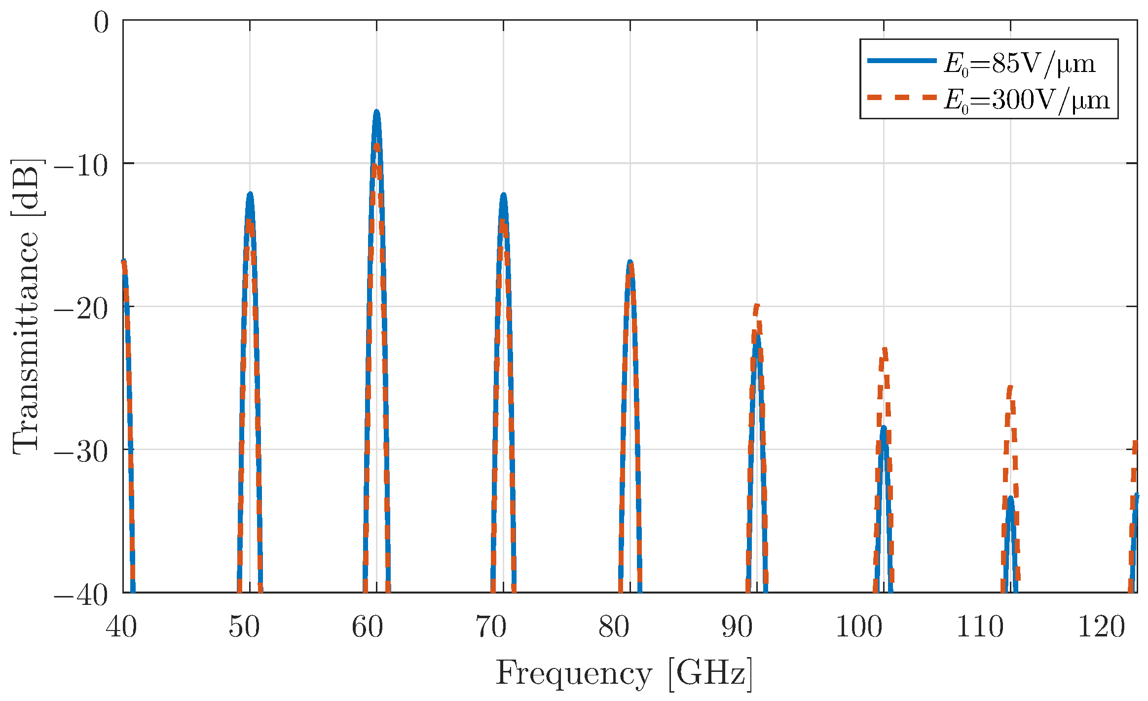
The results of the transmitted or scattered wave for the time-modulated surface are shown in
Figure 2, highlighting the generation of harmonics lower and higher than the central one. In particular, the generated harmonics are observed at
, as reported in previous studies of time-varying media [
12,
14,
15]. Although the transmitted power decreases with increasing harmonic order, this effect is more pronounced for the smaller bias value. This behaviour is attributed to the near-zero conductivity differentiation at lower chemical potentials, as explained in
Figure 1. Therefore, the effect of higher-order harmonic scattering from time-varying surfaces, including a modulated graphene sheet, can be further utilised in more complex design concepts, such as non-linear antennas.
3. Cavity Resonator with Graphene-Coated Aperture
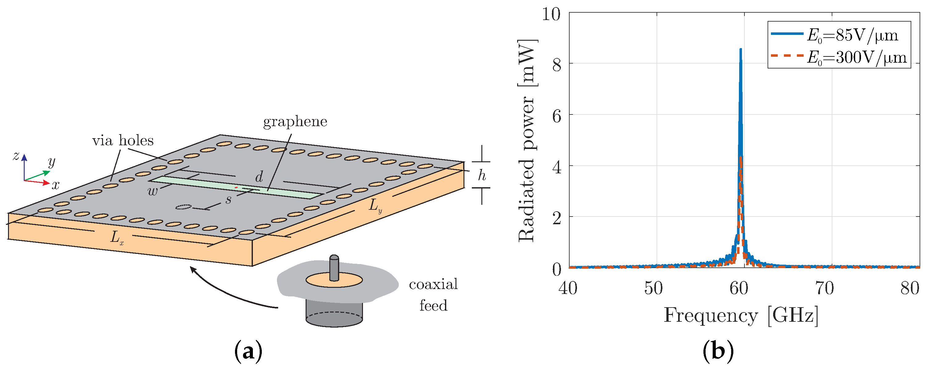
After demonstrating the properties of time-varying graphene in the previous section, we now create a non-linear antenna by placing a time-modulated graphene on a cavity resonator structure. The cavity resonator is, herein, implemented using SIW technology [
1,
7] as illustrated in
Figure 3a. The structure is composed of two perfect electric conductor (PEC) layers on the two sides of the RT/duroid 5880 substrate, with a thickness of
mm, a relative permittivity of
, and a dissipation factor of
. Metallic-coated via holes are drilled inside the substrate, with a diameter of
= 100 μm and a pitch of
= 210 μm, forming a cavity with dimensions
mm. The excitation for the cavity is realised by inserting the core of a coaxial connector in the substrate located at distance
mm from the centre towards the
-axis. Finally, an aperture is formed at the top layer with dimensions of
mm and
= 90 μm, which is covered by graphene with scattering rate set to
meV at room temperature. Note that the proposed structure can be designed in a conformal manner since the confinement functionality of the via holes is not degraded by the curvature [
34,
35], while graphene can, also, operate conformally [
36]. Finally, it must be mentioned that the analysis is purely numerical since graphene is beyond the fabrication capabilities of our laboratory.
The FDTD simulation domain is discretised into mesh cells with a cell size of = 27 μm and a time-step of 50 fs. Open boundaries are truncated using a 16-cell thick Perfectly Matched Layer (PML), and the stimulation is achieved with a broadband pulse centred at 60 GHz and an input power of 100 mW.
Initially, the cavity with a graphene layer at its aperture is simulated without time modulation to evaluate its conventional performance. The total radiated power is shown in
Figure 3b, confirming the cavity antenna’s operation at the desired frequency of
= 60 GHz. Notably, the radiated power is lower than the input power due to the conductive properties of graphene in the millimeter-wave regime. This reduction becomes more pronounced under a bias field of
= 300 V/μm, as the surface conductivity of graphene increases with the absolute value of the chemical potential. In the next subsections, the three modulation types, introduced in the previous section, are implemented in the proposed cavity resonator, and their effects are discussed using a modulation frequency
/6 = 2
π × 10 GHz.
3.1. Harmonic Modulation of Graphene Using Constant Bias
At this stage, the first type of harmonic modulation, discussed in
Section 2.1, is activated in the graphene-coated aperture, and the corresponding simulation results are presented in
Figure 4. This modulation mechanism allows the antenna to shift its operating frequencies beyond the fundamental mode. Specifically, the up-converted frequencies correspond to higher harmonic components, which become visible as a result of the time modulation of the graphene aperture.
It is important to note that when the bias field is set to a lower constant value, a larger portion of the radiated power is concentrated at the fundamental frequency and the low-order harmonics. However, as predicted in
Section 2.3, this occurs at the expense of power at the higher harmonic frequencies, where the radiated power decreases significantly. This trend aligns with the theoretical predictions and validates the system’s behaviour under varying bias conditions. To better understand this trade-off in power distribution across harmonics, a detailed investigation is conducted by analysing the modulation depth at different bias field values.
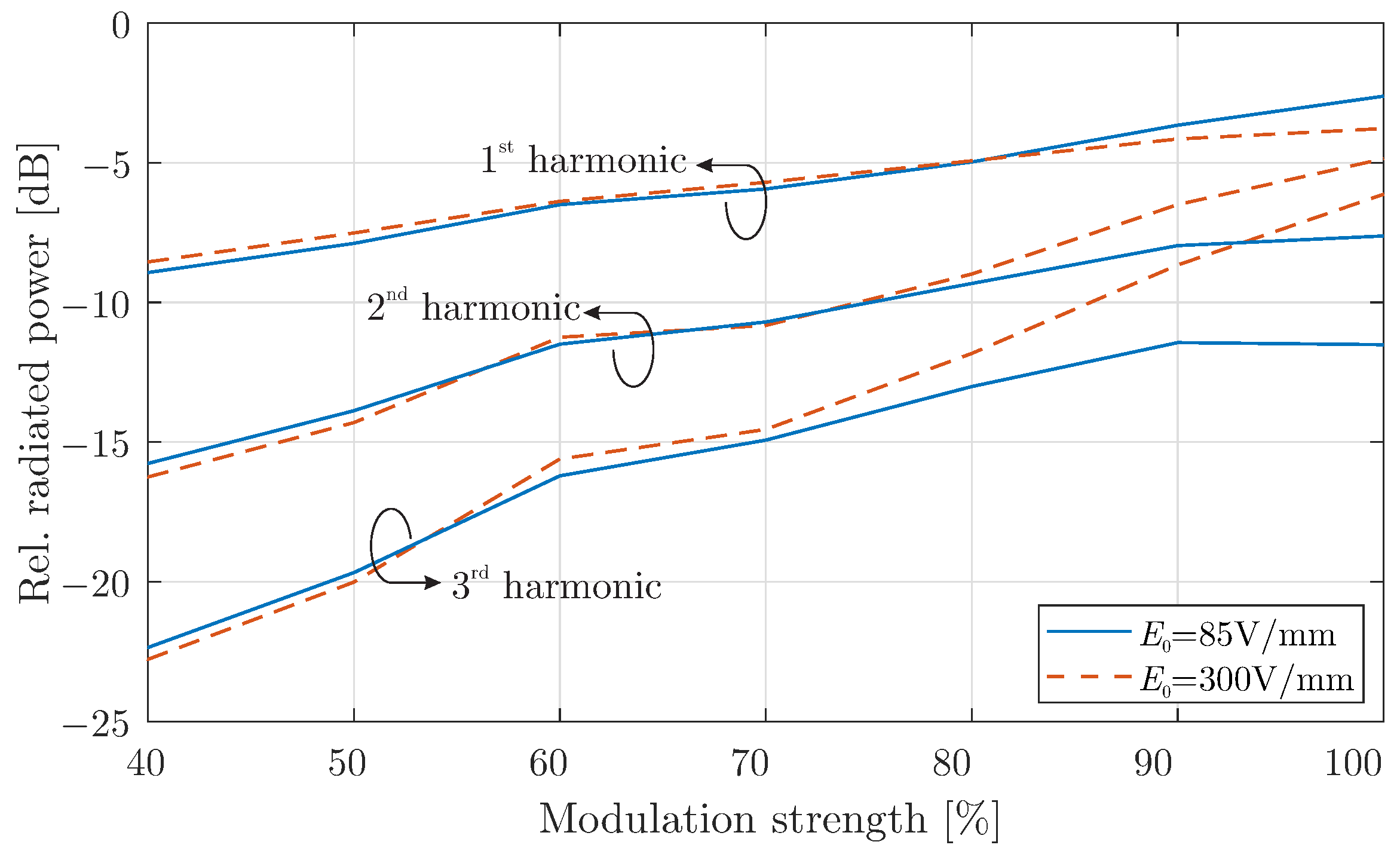
In
Figure 5, the relative radiated power, defined as the ratio of the harmonic power to the power at the fundamental frequency, is plotted as a function of the modulation depth. The results indicate that when the modulation strength exceeds 90% or
, a noticeable shift in the relative power distribution across harmonic components occurs. Specifically, beyond this modulation threshold, the power associated with higher harmonics begins to increase significantly. As the modulation depth is further amplified, the radiated power at higher harmonics continues to grow, enhancing the up-conversion process. This demonstrates that modulation depth is a key factor in optimising the performance of the graphene-modulated cavity antenna at millimeter-wave frequencies, particularly for applications requiring efficient frequency conversion at higher harmonics.
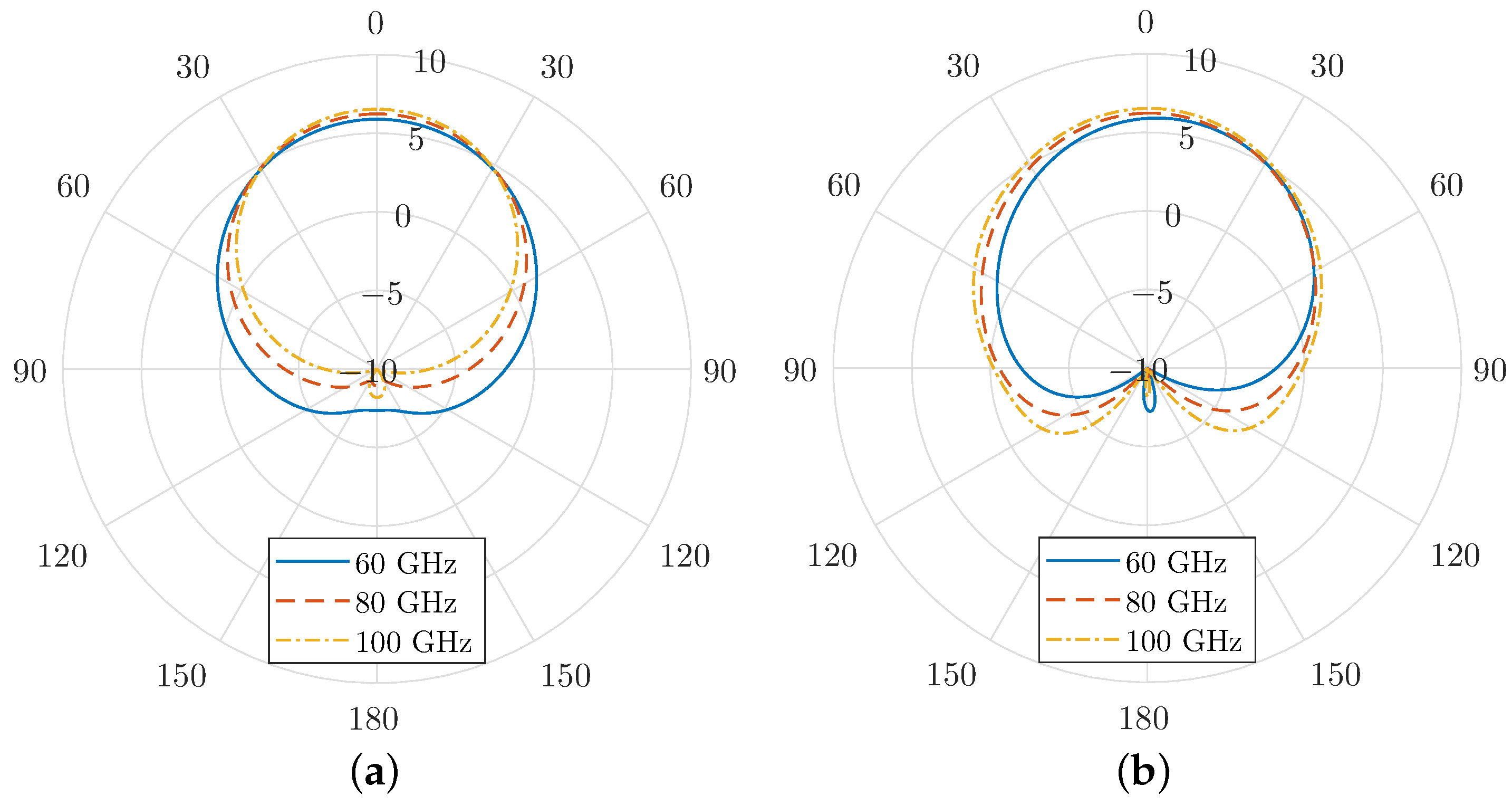
Finally, the radiation patterns for both the
E-plane and
H-plane are shown in
Figure 6 for various harmonic frequencies. These patterns highlight the directional characteristics of the antenna at different harmonic modes. It is evident that the modulation scheme employed in the graphene-coated aperture has minimal impact on the antenna’s core radiation characteristics. The primary lobe, oriented normal to the aperture, remains the dominant feature in the radiation pattern, with a peak gain of approximately 6 dBi. Additionally, the half-power beamwidth (HPBW) is relatively wide, indicating that the antenna maintains strong directional radiation while covering a broad angular range.
Notably, the side-lobe levels remain low across all harmonics, minimising unwanted radiation in off-axis directions. This is a critical performance aspect, as high side-lobes can cause inefficiencies and interference in practical applications. Furthermore, the front-to-back ratio consistently measures around −20 dB, confirming the antenna’s ability to suppress backward radiation effectively. The geometric properties of the SIC antenna support this statement, since the PEC regions cover it entirely except for the open slot on its upper plane. As a result, the forward gain is enhanced, and interference with other components or systems is suppressed.
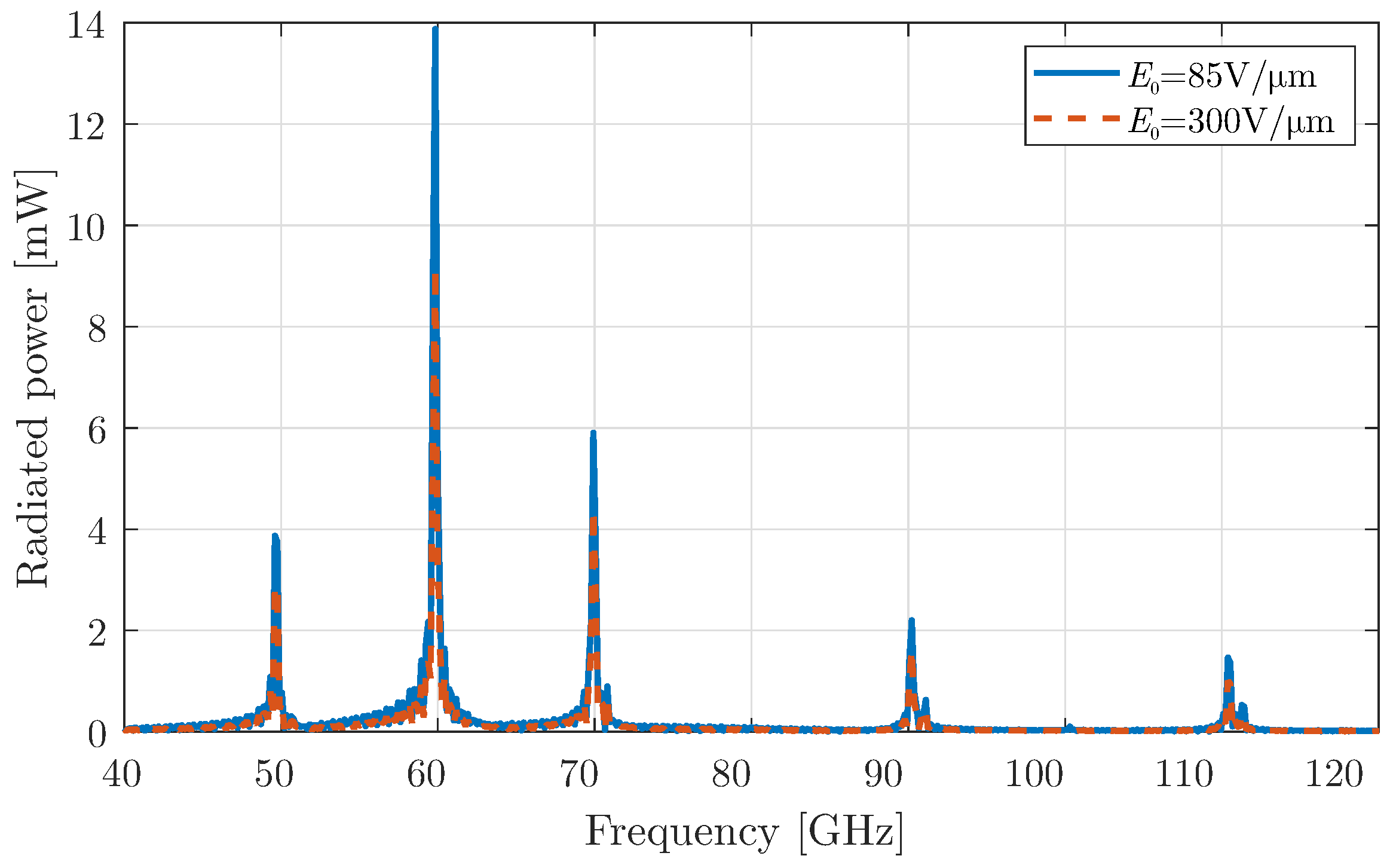
3.2. Periodic Pulse Modulation of Graphene Using Constant Bias
Continuing our analysis, we now apply the second modulation type of
Section 2.1 to graphene, the periodic rectangular pulse. This modulation can be realised using a simple switch, such as am mm-wave PIN diode [
37,
38], which introduces discontinuities at the “on/off” states and provides a rich spectrum. As in the previous case, the periodic pulse alternates between a constant bias, with the modulation strength again set to
. The radiated power of the device is depicted in
Figure 7. The figure illustrates that the even harmonics are eliminated, and the radiated frequencies are
GHz, where
. An additional interesting feature is the enhancement of the radiated power at higher harmonics, such as at 100 GHz, compared to the simple harmonic modulation of the previous case. An explanation for this behaviour can be attributed to the multiple reflections inside the cavity. In particular, the reflection-transmission system of a PEC wall and a graphene interface acts as a time-varying Fabry–Perot cavity and, under certain dimensions, could enhance the generation of higher-order harmonics.
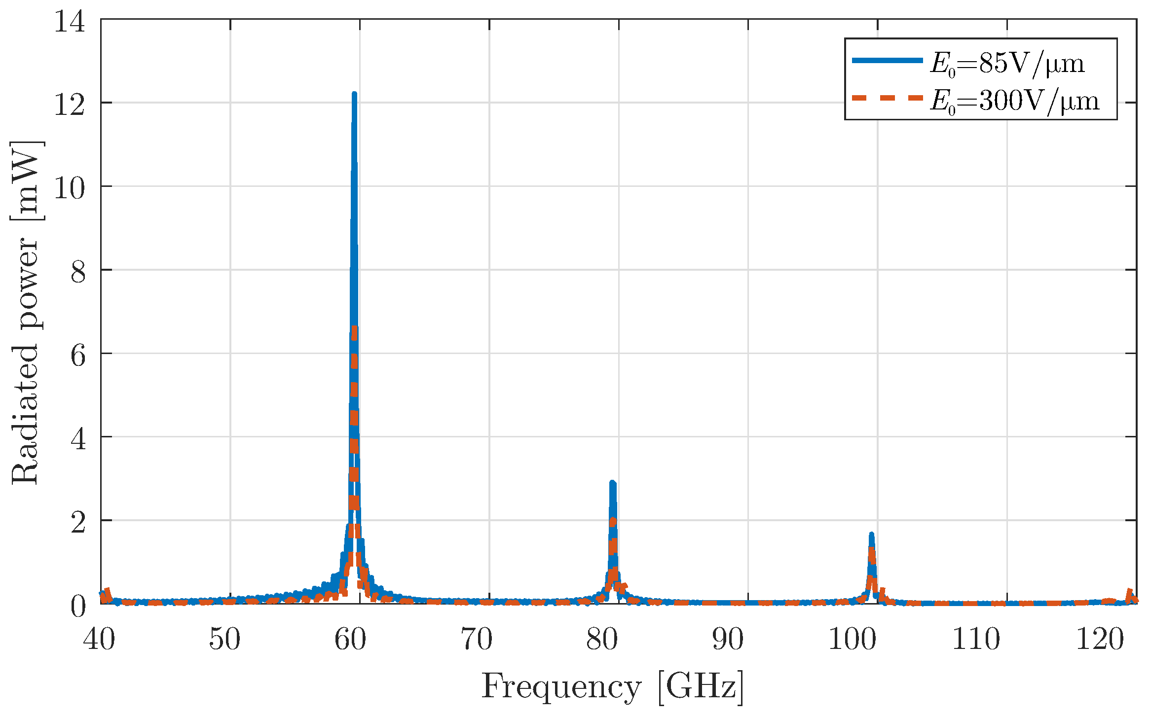
3.3. Harmonic Modulation of Graphene Without Constant Bias
As a final investigation, the harmonic modulation is retrieved, but without a constant bias: specifically, the third modulation type of
Section 2.1. Here, the chemical potential values alternate around “zero”, a value that is related to the minimum surface conductivity of graphene. Note that two different values for
, i.e., the peak bias field, are investigated. The extracted results for the radiated power are illustrated in
Figure 8, showing that the odd harmonics are now eliminated, and antenna radiates at the frequencies
GHz, where
.
This behaviour can be attributed to the even symmetry of the conductivity function with respect to the chemical potential
, originating from the frequency-independent term
, i.e., the red solid line shown in
Figure 1. In particular, considering an alteration of
around “zero”,
acquires absolute-like values, which have even symmetry. On the other hand, if the constant bias of
Section 3.1 is applied,
obtains only positive values and the dependence on
is almost linear.
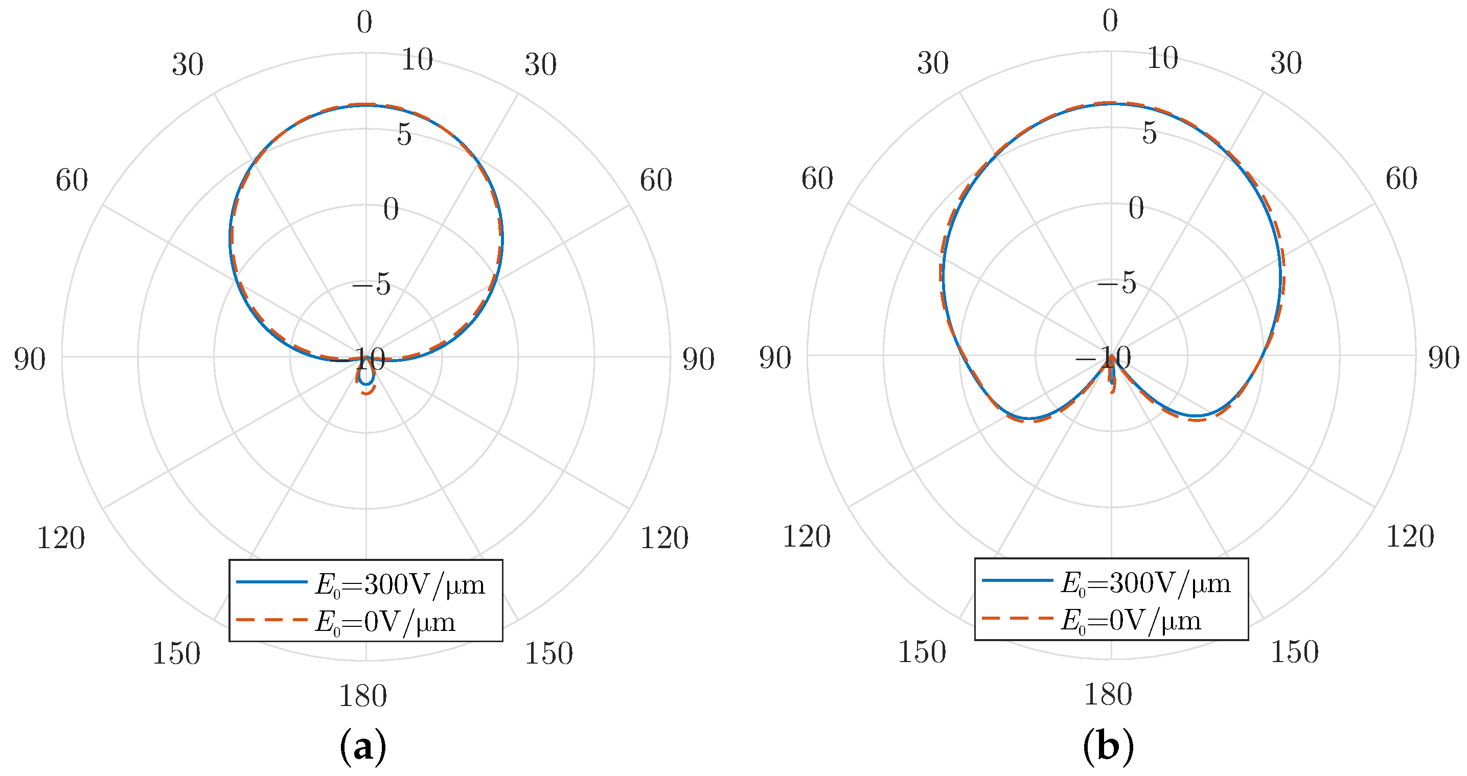
As a consequence, in the absence of constant bias, the surface conductivity is also an absolute-like function with even symmetry. If it is expanded into polynomial terms, only the even terms remain, which are subsequently inherited by the harmonic modulation. As a result, only the even harmonics persist and are considerably enhanced compared to the harmonic modulation case with a constant bias. In particular, the radiated power at 100 GHz is now almost 10 times higher. Finally,
Figure 9 compares the radiation patterns for the cases with and without a constant bias. It is evident that the constant bias does not influence the radiation properties significantly, as these depend mainly on the geometric details rather than the bias characteristics.
4. Discussion
The time-varying systems have recently received much attention due to their remarkable features, such as harmonic frequency generation. In this context, we proposed an SIC antenna with integrated time-varying graphene on its aperture. This approach operates at the mm-wave/THz spectra, where there is a shortage of sources and other communication components. As a result, it deviates from the related literature which focuses on the microwave spectrum using components with spatio-temporal variations for both frequency generation and anomalous reflection [
39,
40,
41].
Indeed, there are a few papers of time-varying graphene-based devices in mm-wave/THz regime, which can generate harmonics. In [
42], the effect on surface wave propagation is studied rather than the radiation in the free space. The latter is examined in [
26,
43] for periodic graphene arrangements, where the generated harmonics are vanishing after the third order. However, in our work, we propose additionally a mechanism for enhancing these generated harmonics, via the cavity mechanism and the utilisation of additional modulation schemes. As a consequence, harmonics of the fourth and fifth order have a considerable portion of power, as depicted in
Figure 7 and
Figure 8, respectively.
Finally, a couple of key challenges were identified that can optimise the enhanced frequency conversion. Firstly, a proper geometric arrangement is able to exploit the multiple reflections inside the cavity. This can help to augment certain frequencies, similarly to a Fabry–Perot resonator. Moreover, the application of more advanced modulation schemes along with the inherent time-varying ability of graphene’s chemical potential can amplify the desired harmonics.
5. Conclusions
In this paper, we have presented a non-linear antenna design by the integration of a well-documented SIC slot antenna with time-varying graphene, for the generation of higher-order frequencies in the mm-wave spectrum. First, graphene was modelled as having a surface conductivity with Drude dispersion. Time modulation was theoretically introduced in graphene via the alteration of the electric bias field, while time-varying graphene was numerically simulated using an efficient modified FDTD algorithm. Then, the proposed structure was numerically simulated for three different types of time modulation, and results show a successful harmonic generation. Specifically, the higher-order harmonics can be enhanced with a modulation strength larger than , while the even or odd orders of harmonics can be enhanced by using certain types of periodic modulation of the bias field. Finally, the radiation characteristics of the SIC graphene antenna, designed for the central frequency , are retained for the neighbouring higher-order harmonics, signifying the effective use of the proposed device for a frequency up-conversion.
As for future work, we aim to equivalently expand the proposed design methodology to include other time-varying surfaces, like space–time metasurfaces. Indeed, 2D arrays of subwavelength particles can be expressed with a surface susceptibility that follows the Lorentz dispersion model; thus, one can utilise the proposed design to include non-linear antennas with time-varying metasurfaces. This type of antenna, if time-modulated elements could be implemented, could be easier to fabricate and ultimately measure for performance. Moreover, additional features could be added on the proposed design for the purpose of filtering or enhancing specific higher-order harmonics. Towards this goal, analytic formulations of the proposed designs as well as extensive use of optimisation or inverse-design techniques would be interesting and beneficial.
Author Contributions
S.A. developed the conceptualisation and the methodology and performed the formal analysis, the investigation, and the writing/original draft preparation. T.K. participated in the conceptualisation, the original draft preparation, and the review and editing. F.L. and N.V.K. participated in the review and editing, as well as the supervision and project administration. All authors have read and agreed to the published version of the manuscript.
Funding
This research received no external funding.
Data Availability Statement
Data available from the authors upon reasonable request.
Conflicts of Interest
The authors declare no conflicts of interest.
References
- Deslandes, D.; Wu, K. Single-substrate integration technique of planar circuits and waveguide filters. IEEE Trans. Microw. Theory Tech. 2003, 51, 593–596. [Google Scholar] [CrossRef]
- Amanatiadis, S.; Salonikios, V.; Nitas, M.; Zygiridis, T.; Kantartzis, N.; Yioultsis, T. Sensitivity Analysis of Metamaterial-Inspired SIW Focusing on Resonator Misalignment. IEEE Access 2024, 12, 63942–63949. [Google Scholar] [CrossRef]
- Moscato, S.; Tomassoni, C.; Bozzi, M.; Perregrini, L. Quarter-mode cavity filters in substrate integrated waveguide technology. IEEE Trans. Microw. Theory Tech. 2016, 64, 2538–2547. [Google Scholar] [CrossRef]
- Ye, X.F.; Zheng, S.Y.; Pan, Y.M. A compact millimeter-wave patch quadrature coupler with a wide range of coupling coefficients. IEEE Microw. Wirel. Components Lett. 2016, 26, 165–167. [Google Scholar] [CrossRef]
- Khan, A.A.; Mandal, M.K. Miniaturized substrate integrated waveguide (SIW) power dividers. IEEE Microw. Wirel. Components Lett. 2016, 26, 888–890. [Google Scholar] [CrossRef]
- Cassivi, Y.; Wu, K. Low cost microwave oscillator using substrate integrated waveguide cavity. IEEE Microw. Wirel. Components Lett. 2003, 13, 48–50. [Google Scholar] [CrossRef]
- Bozzi, M.; Georgiadis, A.; Wu, K. Review of substrate-integrated waveguide circuits and antennas. IET Microw. Antennas Propag. 2011, 5, 909–920. [Google Scholar] [CrossRef]
- Mukherjee, S.; Biswas, A. Design of self-diplexing substrate integrated waveguide cavity-backed slot antenna. IEEE Antennas Wirel. Propag. Lett. 2016, 15, 1775–1778. [Google Scholar] [CrossRef]
- Asaadi, M.; Sebak, A. High-Gain Low-Profile Circularly Polarized Slotted SIW Cavity Antenna for MMW Applications. IEEE Antennas Wirel. Propag. Lett. 2017, 16, 752–755. [Google Scholar] [CrossRef]
- Zhu, Q.; Ng, K.B.; Chan, C.H.; Luk, K.M. Substrate-integrated-waveguide-fed array antenna covering 57–71 GHz band for 5G applications. IEEE Trans. Antennas Propag. 2017, 65, 6298–6306. [Google Scholar] [CrossRef]
- Lu, R.; Yu, C.; Zhu, Y.; Xia, X.; Hong, W. Millimeter-Wave Dual-Band Dual-Polarized SIW Cavity-Fed Filtenna for 5G Applications. IEEE Trans. Antennas Propag. 2022, 70, 10104–10112. [Google Scholar] [CrossRef]
- Caloz, C.; Deck-Léger, Z.L. Spacetime metamaterials—Part I: General concepts. IEEE Trans. Antennas Propag. 2019, 68, 1569–1582. [Google Scholar] [CrossRef]
- Caloz, C.; Deck-Leger, Z.L. Spacetime metamaterials—Part II: Theory and applications. IEEE Trans. Antennas Propag. 2019, 68, 1583–1598. [Google Scholar] [CrossRef]
- Galiffi, E.; Tirole, R.; Yin, S.; Li, H.; Vezzoli, S.; Huidobro, P.A.; Silveirinha, M.G.; Sapienza, R.; Alù, A.; Pendry, J.B. Photonics of time-varying media. Adv. Photonics 2022, 4, 014002. [Google Scholar] [CrossRef]
- Mostafa, M.; Mirmoosa, M.; Sidorenko, M.; Asadchy, V.; Tretyakov, S. Temporal interfaces in complex electromagnetic materials: An overview. Opt. Mater. Express 2024, 14, 1103–1127. [Google Scholar] [CrossRef]
- Asgari, M.M.; Garg, P.; Wang, X.; Mirmoosa, M.S.; Rockstuhl, C.; Asadchy, V. Photonic time crystals: Theory and applications. arXiv 2024, arXiv:2404.04899. [Google Scholar] [CrossRef]
- Asadchy, V.; Lamprianidis, A.; Ptitcyn, G.; Albooyeh, M.; Rituraj; Karamanos, T.; Alaee, R.; Tretyakov, S.; Rockstuhl, C.; Fan, S. Parametric Mie Resonances and Directional Amplification in Time-Modulated Scatterers. Phys. Rev. Appl. 2022, 18, 054065. [Google Scholar] [CrossRef]
- Pacheco-Peña, V.; Kiasat, Y.; Solís, D.M.; Edwards, B.; Engheta, N. Holding and amplifying electromagnetic waves with temporal non-Foster metastructures. arXiv 2023, arXiv:2304.03861. [Google Scholar] [CrossRef]
- Wang, X.; Mirmoosa, M.S.; Asadchy, V.S.; Rockstuhl, C.; Fan, S.; Tretyakov, S.A. Metasurface-based realization of photonic time crystals. Sci. Adv. 2023, 9, eadg7541. [Google Scholar] [CrossRef]
- Ramaccia, D.; Sounas, D.L.; Alù, A.; Toscano, A.; Bilotti, F. Phase-Induced Frequency Conversion and Doppler Effect With Time-Modulated Metasurfaces. IEEE Trans. Antennas Propag. 2020, 68, 1607–1617. [Google Scholar] [CrossRef]
- Hadad, Y.; Sounas, D. Space-time modulated loaded-wire metagratings for magnetless nonreciprocity and near-complete frequency conversion. Opt. Mater. Express 2024, 14, 1295–1308. [Google Scholar] [CrossRef]
- Pacheco-Peña, V.; Engheta, N. Antireflection temporal coatings. Optica 2020, 7, 323–331. [Google Scholar] [CrossRef]
- Zhang, L.; Chen, X.Q.; Liu, S.; Zhang, Q.; Zhao, J.; Dai, J.Y.; Bai, G.D.; Wan, X.; Cheng, Q.; Castaldi, G.; et al. Space-time-coding digital metasurfaces. Nat. Commun. 2018, 9, 4334. [Google Scholar] [CrossRef] [PubMed]
- Yang, J.; Chen, J.; Quan, L.; Chen, X.; Shi, H.; Xue, W.; Liu, Y. Dynamic radiation steering with transmission-type coding metasurface. Opt. Express 2022, 30, 28038–28048. [Google Scholar] [CrossRef]
- Altares Menendez, G.; Maes, B. Frequency comb generation using plasmonic resonances in a time-dependent graphene ribbon array. Phys. Rev. B 2017, 95, 144307. [Google Scholar] [CrossRef]
- Salary, M.M.; Jafar-Zanjani, S.; Mosallaei, H. Time-varying metamaterials based on graphene-wrapped microwires: Modeling and potential applications. Phys. Rev. B 2018, 97, 115421. [Google Scholar] [CrossRef]
- Barati Sedeh, H.; Salary, M.M.; Mosallaei, H. Active Multiple Access Secure Communication Enabled by Graphene-Based Time-Modulated Metasurfaces. IEEE Trans. Antennas Propag. 2022, 70, 664–679. [Google Scholar] [CrossRef]
- Amanatiadis, S.; Karamanos, T.; Salonikios, V.; Kantartzis, N.; Yioultsis, T. A Combined Substrate-integrated Cavity with Time-modulated Graphene Aperture for the Effective Frequency Generation at the THz Regime. In Proceedings of the 2023 Seventeenth International Congress on Artificial Materials for Novel Wave Phenomena (Metamaterials), Chania, Greece, 11–16 September 2023; pp. X-007–X-009. [Google Scholar] [CrossRef]
- Gusynin, V.; Sharapov, S.; Carbotte, J. Magneto-optical conductivity in graphene. J. Phys. Condens. Matter 2006, 19, 026222. [Google Scholar] [CrossRef]
- Garg, P.; Lamprianidis, A.G.; Beutel, D.; Karamanos, T.; Verfürth, B.; Rockstuhl, C. Modeling four-dimensional metamaterials: A T-matrix approach to describe time-varying metasurfaces. Opt. Express 2022, 30, 45832–45847. [Google Scholar] [CrossRef]
- Ptitcyn, G.; Lamprianidis, A.; Karamanos, T.; Asadchy, V.; Alaee, R.; Müller, M.; Albooyeh, M.; Mirmoosa, M.S.; Fan, S.; Tretyakov, S.; et al. Floquet–Mie Theory for Time-Varying Dispersive Spheres. Laser Photonics Rev. 2023, 17, 2100683. [Google Scholar] [CrossRef]
- Bouzianas, G.D.; Kantartzis, N.V.; Yioultsis, T.V.; Tsiboukis, T.D. Consistent study of graphene structures through the direct incorporation of surface conductivity. IEEE Trans. Magn. 2014, 50, 161–164. [Google Scholar] [CrossRef]
- TS 38.101-2: NR; User Equipment (UE) Radio Transmission and Reception; Part 2: Range 2 Standalone. 3GPP: Sophia Antipolis, France, 2024.
- Cheng, Y.J.; Xu, H.; Ma, D.; Wu, J.; Wang, L.; Fan, Y. Millimeter-wave shaped-beam substrate integrated conformal array antenna. IEEE Trans. Antennas Propag. 2013, 61, 4558–4566. [Google Scholar] [CrossRef]
- Çelenk, E.; Tokan, N.T. Frequency scanning conformal sensor based on SIW metamaterial antenna. IEEE Sens. J. 2021, 21, 16015–16023. [Google Scholar] [CrossRef]
- Hussain, M.; Zahra, H.; Abbas, S.M.; Zhu, Y. Flexible dielectric materials: Potential and applications in antennas and RF sensors. Adv. Electron. Mater. 2024, 10, 2400240. [Google Scholar] [CrossRef]
- Kamoda, H.; Iwasaki, T.; Tsumochi, J.; Kuki, T. 60-GHz electrically reconfigurable reflectarray using pin diode. In Proceedings of the 2009 IEEE MTT-S International Microwave Symposium Digest, Boston, MA, USA, 7–12 June 2009; pp. 1177–1180. [Google Scholar]
- Gong, Y.; Teng, J.W.; Cressler, J.D. A compact, high-power, 60 GHz SPDT switch using shunt-series SiGe PIN diodes. In Proceedings of the 2019 IEEE Radio Frequency Integrated Circuits Symposium (RFIC), Boston, MA, USA, 2–4 June 2019; pp. 15–18. [Google Scholar]
- Taravati, S.; Eleftheriades, G.V. Microwave space-time-modulated metasurfaces. ACS Photonics 2022, 9, 305–318. [Google Scholar] [CrossRef]
- Wang, S.R.; Dai, J.Y.; Zhou, Q.Y.; Ke, J.C.; Cheng, Q.; Cui, T.J. Manipulations of multi-frequency waves and signals via multi-partition asynchronous space-time-coding digital metasurface. Nat. Commun. 2023, 14, 5377. [Google Scholar] [CrossRef]
- Moreno-Rodríguez, S.; Alex-Amor, A.; Padilla, P.; Valenzuela-Valdés, J.F.; Molero, C. Space-time metallic metasurfaces for frequency conversion and beamforming. Phys. Rev. Appl. 2024, 21, 064018. [Google Scholar] [CrossRef]
- Shirokova, A.; Maslov, A.; Bakunov, M. Surface plasmon transformation on dynamic graphene with a periodic modulation of carrier density. Phys. Rev. B 2023, 108, 245139. [Google Scholar] [CrossRef]
- Rahmanzadeh, M.; Rejaei, B.; Khavasi, A. Analysis of electromagnetic scattering from array of time-modulated graphene ribbons. Opt. Express 2023, 31, 21739–21752. [Google Scholar] [CrossRef]
| Disclaimer/Publisher’s Note: The statements, opinions and data contained in all publications are solely those of the individual author(s) and contributor(s) and not of MDPI and/or the editor(s). MDPI and/or the editor(s) disclaim responsibility for any injury to people or property resulting from any ideas, methods, instructions or products referred to in the content. |
© 2025 by the authors. Licensee MDPI, Basel, Switzerland. This article is an open access article distributed under the terms and conditions of the Creative Commons Attribution (CC BY) license (https://creativecommons.org/licenses/by/4.0/).

 ,
, 