
Enhanced Micromixing Using Surface Acoustic Wave Devices: Fundamentals, Designs, and Applications


Abstract

1. Introduction
2. Fundamentals
2.1. Mixing Behavior in Microfluidic Environments
2.2. SAW Devices
2.3. Configurations and Materials of IDTs
- A.
- Unidirectional IDTs: Unidirectional IDTs are designed to address the bidirectional effect and transmit SAW energy primarily in one direction. Several different IDT configurations can be used to achieve a unidirectional function. The most commonly used are the single-phase unidirectional transducers (SPUDTs). It can reduce bidirectional loss and minimize triple transmission echo in SAW devices. Enhancing the unidirectionality is also found to be an effective way to suppress insertion loss. There are several SPUDT cell designs, in which the electrode-width-controlled (EWC) cell is the best known. A traditional EWC-SPUDT cell consists of three finger electrodes (as shown in Figure 3c) [73], two adjacent narrow electrodes, and one wide electrode, whose widths are λ/8 and λ/4, respectively. The gap distance between the two adjacent narrow fingers is λ/8, and that between the narrow finger and the wide finger is 3λ/16. However, there are other design versions of the electrode width and gap distances for an EWC-type SPUDT. Another type of unidirectional IDT employs floating electrodes, as shown in Figure 3d, which is called floating electrode unidirectional transducers (FEUDTs) [74]. The floating electrodes are not connected to any electric potential and do not contribute to the generation of the wave. Instead, they are used to minimize the insertion loss by lowering electrode resistance, reducing parasitic capacitance, improving wave propagation, and providing better impedance matching.
- B.
- Chirped IDTs: This type of IDT can generate broadband response by linearly or nonlinearly modulating the width and spacing of the interdigital fingers, as shown in Figure 3e [75]. This geometric modulation yields a gradient change in the finger pitch, which can generate SAWs with different resonant frequencies and considerably enlarge the bandwidth. The broadband characteristics of the chirped IDTs enable precise control of the SAW propagation properties, such as the wavelength of the excited SAWs. Typically, chirped IDTs require sophisticated design and fabrication techniques. However, they have the advantage of being able to customize the spectrum profile or compensate for dispersion effects caused by substrate materials or device geometry. Chirped IDTs are particularly well suited for manipulating droplets and particles in stationary fluids with an additional degree of freedom by continuously varying or tuning the operating frequency. The frequency tunability of chirped IDTs may also be suitable for adapting wavelength-sensitive fluid manipulation in microstructures.
- C.
- SFITs: They can also be used to produce a broadband response similar to that of a chirped IDT, allowing the SAW to be tuned over a range of frequencies. However, the difference is that the period of the electrodes is changed by tilting their arrangement, rather than modulating the width and spacing of the fingers along the transverse direction [76]. Therefore, the IDT has a fan-shaped or tapered configuration, as shown in Figure 3f. The advantage of this configuration is that the position of the excited SAW beam can be controlled depending on the frequency. As with the chirped IDTs, this design may also require complex optimization and fabrication processes. By tailoring the angle of the IDT fingers and optimizing the slant geometry, the desired bandwidth and transduction characteristics of SAWs can be achieved.
- D.
- Focused IDTs: Unlike previous IDT designs, focused IDTs (as shown in Figure 3g) utilize curved electrode fingers to concentrate acoustic energy into a narrow beam, pinpointing a small focal point [77]. It is often used in acoustofluidic micromixers to improve mixing efficiency by utilizing its higher acoustic power intensity. The curved electrode fingers may be in the shape of a simple circular arc. However, since many crystal cuts of piezoelectric materials are strongly anisotropic, some of the literature suggests designing the curved shape of focused IDTs based on the concentric wave surface (slowness surface) so that the angle-dependent SAW energy velocity is precisely directed to the focal point, and the resulting curve may differ from an exact circular arc shape [78,79].
2.4. Acoustofluidics and Acoustic Streaming
3. SAW-Based Microfluidic Mixers
3.1. SAWs Excited by a Straight IDT
3.2. SAWs Excited by a Non-Straight IDT
3.3. Multi-IDT Designs
4. Applications
5. Conclusions and Prospects
Funding
Data Availability Statement
Acknowledgments
Conflicts of Interest
References
- Hajam, M.I.; Khan, M.M. Microfluidics: A concise review of the history, principles, design, applications, and future outlook. Biomater. Sci. 2024, 12, 218–251. [Google Scholar] [CrossRef]
- Niculescu, A.G.; Chircov, C.; Bîrcă, A.C.; Grumezescu, A.M. Fabrication and applications of microfluidic devices: A review. Int. J. Mol. Sci. 2021, 22, 2011. [Google Scholar] [CrossRef]
- Liu, C.; Li, Y.; Liu, B.F. Micromixers and their applications in kinetic analysis of biochemical reactions. Talanta 2019, 205, 120136. [Google Scholar] [CrossRef] [PubMed]
- Gharib, G.; Bütün, İ.; Muganlı, Z.; Kozalak, G.; Namlı, İ.; Sarraf, S.S.; Ahmadi, V.E.; Toyran, E.; van Wijnen, A.J.; Koşar, A. Biomedical applications of microfluidic devices: A review. Biosensors 2022, 12, 1023. [Google Scholar] [CrossRef] [PubMed]
- Mumtaz, Z.; Rashid, Z.; Ali, A.; Arif, A.; Ameen, F.; AlTami, M.S.; Yousaf, M.Z. Prospects of microfluidic technology in nucleic acid detection approaches. Biosensors 2023, 13, 584. [Google Scholar] [CrossRef] [PubMed]
- Alidoust, M.; Baharfar, M.; Manouchehri, M.; Yamini, Y.; Tajik, M.; Seidi, S. Emergence of microfluidic devices in sample extraction; an overview of diverse methodologies, principals, and recent advancements. TrAC Trends Anal. Chem. 2021, 143, 116352. [Google Scholar] [CrossRef]
- Nilghaz, A.; Mousavi, S.M.; Li, M.; Tian, J.; Cao, R.; Wang, X. Paper-based microfluidics for food safety and quality analysis. Trends Food Sci. Technol. 2021, 118, 273–284. [Google Scholar] [CrossRef]
- Lu, N.; Tay, H.M.; Petchakup, C.; He, L.; Gong, L.; Maw, K.K.; Leong, S.Y.; Lok, W.W.; Ong, H.B.; Guo, R.; et al. Label-free microfluidic cell sorting and detection for rapid blood analysis. Lab A Chip 2023, 23, 1226–1257. [Google Scholar] [CrossRef]
- Zhang, X.; Xu, X.; Wang, J.; Wang, C.; Yan, Y.; Wu, A.; Ren, Y. Public-health-driven microfluidic technologies: From separation to detection. Micromachines 2021, 12, 391. [Google Scholar] [CrossRef]
- Chen, T.; Huang, C.; Wang, Y.; Wu, J. Microfluidic methods for cell separation and subsequent analysis. Chin. Chem. Lett. 2022, 33, 1180–1192. [Google Scholar] [CrossRef]
- Mesquita, P.; Gong, L.; Lin, Y. Low-cost microfluidics: Towards affordable environmental monitoring and assessment. Front. Lab A Chip Technol. 2022, 1, 1074009. [Google Scholar] [CrossRef]
- Yang, S.M.; Lv, S.; Zhang, W.; Cui, Y. Microfluidic point-of-care (POC) devices in early diagnosis: A review of opportunities and challenges. Sensors 2022, 22, 1620. [Google Scholar] [CrossRef] [PubMed]
- Zhou, W.M.; Yan, Y.Y.; Guo, Q.R.; Ji, H.; Wang, H.; Xu, T.T.; Makabel, B.; Pilarsky, C.; He, G.; Yu, X.Y.; et al. Microfluidics applications for high-throughput single cell sequencing. J. Nanobiotechnology 2021, 19, 312. [Google Scholar] [CrossRef] [PubMed]
- Haghighinia, A.; Movahedirad, S. Mass transfer in a novel passive micro-mixer: Flow tortuosity effects. Anal. Chim. Acta 2020, 1098, 75–85. [Google Scholar] [CrossRef]
- Nguyen, N.T.; Wu, Z. Micromixers—A review. J. Micromech. Microeng. 2004, 15, R1. [Google Scholar] [CrossRef]
- Fang, J.Z.; Lee, D.J. Micromixing efficiency in static mixer. Chem. Eng. Sci. 2001, 56, 3797–3802. [Google Scholar] [CrossRef]
- Liu, J.; Zeng, S.; Zhu, H.; Wan, X.; Sohan, A.M.F.; Yin, B. A portable automated microfluidic platform for point-of-care testing for multiple mycotoxins in wine. Foods 2024, 13, 2066. [Google Scholar] [CrossRef]
- Hessel, V.; Löwe, H.; Schönfeld, F. Micromixers—A review on passive and active mixing principles. Chem. Eng. Sci. 2005, 60, 2479–2501. [Google Scholar] [CrossRef]
- Wong, W.D.; Majnis, M.F.; Lai, C.W.; Sagadevan, S.; Julkapli, N.M. Enhancement of mixing and reaction efficiency of various fluids applications at different microfluidic configuration and design. Chem. Eng. Process.-Process Intensif. 2024, 198, 109729. [Google Scholar] [CrossRef]
- Gervais, T.; Jensen, K.F. Mass transport and surface reactions in microfluidic systems. Chem. Eng. Sci. 2006, 61, 1102–1121. [Google Scholar] [CrossRef]
- Agnihotri, P. Analysis of interfacial mixing zone and mixing index in microfluidic channels. Microfluid. Nanofluidics 2023, 27, 12. [Google Scholar] [CrossRef]
- Tripathi, E.; Patowari, P.K.; Pati, S. Comparative assessments of mixing and pressure drop characteristics in spiral, serpentine and straight micromixers. Meccanica 2023, 58, 1315–1327. [Google Scholar] [CrossRef]
- Ulkir, O.; Girit, O.; Ertugrul, I. Design and analysis of a laminar diffusion-based micromixer with microfluidic chip. J. Nanomater. 2021, 2021, 6684068. [Google Scholar] [CrossRef]
- Soltani, D.; Persoons, T.; Alimohammadi, S. Micromixing strategies for efficient mixing processes: A comprehensive review. J. Micromech. Microeng. 2024, 34, 113001. [Google Scholar] [CrossRef]
- Wang, X.; Liu, Z.; Wang, B.; Cai, Y.; Song, Q. An overview on state-of-art of micromixer designs, characteristics and applications. Anal. Chim. Acta 2023, 1279, 341685. [Google Scholar] [CrossRef]
- Gambhire, S.; Patel, N.; Gambhire, G.; Kale, S. A review on different micromixers and its micromixing within microchannel. Int. J. Curr. Eng. Technol. 2016, 4, 409–413. [Google Scholar]
- Bazaz, S.R.; Sayyah, A.; Hazeri, A.H.; Salomon, R.; Mehrizi, A.A.; Warkiani, M.E. Micromixer research trend of active and passive designs. Chem. Eng. Sci. 2024, 293, 120028. [Google Scholar] [CrossRef]
- Bayareh, M.; Ashani, M.N.; Usefian, A. Active and passive micromixers: A comprehensive review. Chem. Eng. Process.-Process Intensif. 2020, 147, 107771. [Google Scholar] [CrossRef]
- Ward, K.; Fan, Z.H. Mixing in microfluidic devices and enhancement methods. J. Micromech. Microeng. 2015, 25, 094001. [Google Scholar] [CrossRef]
- Shah, I.; Kim, S.W.; Kim, K.; Doh, Y.H.; Choi, K.H. Experimental and numerical analysis of Y-shaped split and recombination micro-mixer with different mixing units. Chem. Eng. J. 2019, 358, 691–706. [Google Scholar] [CrossRef]
- Shi, X.; Wang, L.; Huang, S.; Li, F. A novel passive micromixer with array of Koch fractal obstacles in microchannel. J. Dispers. Sci. Technol. 2021, 42, 236–247. [Google Scholar] [CrossRef]
- Chen, X.; Li, T.; Zeng, H.; Hu, Z.; Fu, B. Numerical and experimental investigation on micromixers with serpentine microchannels. Int. J. Heat Mass Transf. 2016, 98, 131–140. [Google Scholar] [CrossRef]
- Lee, C.Y.; Wang, W.T.; Liu, C.C.; Fu, L.M. Passive mixers in microfluidic systems: A review. Chem. Eng. J. 2016, 288, 146–160. [Google Scholar] [CrossRef]
- Green, J.; Holdø, A.; Khan, A. A review of passive and active mixing systems in microfluidic devices. Int. J. Multiphysics 2007, 1, 1–32. [Google Scholar] [CrossRef]
- Xie, Y.; Todd, N.W.; Liu, Z.; Zhan, M.; Fang, H.; Peng, H.; Alattar, M.; Deepak, J.; Stass, S.A.; Jiang, F. Altered miRNA expression in sputum for diagnosis of non-small cell lung cancer. Lung Cancer 2010, 67, 170–176. [Google Scholar] [CrossRef]
- Rondeau, E.; Cooper-White, J.J. Biopolymer microparticle and nanoparticle formation within a microfluidic device. Langmuir 2008, 24, 6937–6945. [Google Scholar] [CrossRef]
- Choi, E.; Kwon, K.; Lee, S.J.; Kim, D.; Park, J. Non-equilibrium electrokinetic micromixer with 3D nanochannel networks. Lab A Chip 2015, 15, 1794–1798. [Google Scholar] [CrossRef]
- Wang, Y.; Zhe, J.; Chung, B.T.; Dutta, P. A rapid magnetic particle driven micromixer. Microfluid. Nanofluidics 2008, 4, 375–389. [Google Scholar] [CrossRef]
- Zhu, G.P.; Nguyen, N.T. Rapid magnetofluidic mixing in a uniform magnetic field. Lab A Chip 2012, 12, 4772–4780. [Google Scholar] [CrossRef]
- Destgeer, G.; Sung, H.J. Recent advances in microfluidic actuation and micro-object manipulation via surface acoustic waves. Lab A Chip 2015, 15, 2722–2738. [Google Scholar] [CrossRef]
- Nan, K.; Shi, Y.; Zhao, T.; Tang, X.; Zhu, Y.; Wang, K.; Bai, J.; Zhao, W. Mixing and flow transition in an optimized electrokinetic turbulent micromixer. Anal. Chem. 2022, 94, 12231–12239. [Google Scholar] [CrossRef]
- di Toma, A.; Brunetti, G.; Chiriacò, M.S.; Ferrara, F.; Ciminelli, C. A Novel hybrid platform for live/dead bacteria accurate sorting by on-chip DEP device. Int. J. Mol. Sci. 2023, 24, 7077. [Google Scholar] [CrossRef]
- Li, Z.; Zhang, B.; Dang, D.; Yang, X.; Yang, W.; Liang, W. A review of microfluidic-based mixing methods. Sens. Actuators A Phys. 2022, 344, 113757. [Google Scholar] [CrossRef]
- Cai, G.; Xue, L.; Zhang, H.; Lin, J. A review on micromixers. Micromachines 2017, 8, 274. [Google Scholar] [CrossRef]
- Chen, Z.; Shen, L.; Zhao, X.; Chen, H.; Xiao, Y.; Zhang, Y.; Yang, X.; Zhang, J.; Wei, J.; Hao, N. Acoustofluidic micromixers: From rational design to lab-on-a-chip applications. Appl. Mater. Today 2022, 26, 101356. [Google Scholar] [CrossRef]
- Chen, Z.; Liu, P.; Zhao, X.; Huang, L.; Xiao, Y.; Zhang, Y.; Zhang, J.; Hao, N. Sharp-edge acoustic microfluidics: Principles, structures, and applications. Appl. Mater. Today 2021, 25, 101239. [Google Scholar] [CrossRef]
- Mu, S.; Lu, Y.; Zhu, G. Numerical simulation and coupling mechanism study of acoustic-inertial micromixer. Chem. Eng. J. 2024, 480, 147967. [Google Scholar] [CrossRef]
- Wu, H.; Tang, Z.; You, R.; Pan, S.; Liu, W.; Zhang, H.; Li, T.; Yang, Y.; Sun, C.; Pan, W.; et al. Manipulations of micro/nanoparticles using gigahertz acoustic streaming tweezers. Nanotechnol. Precis. Eng. 2022, 5, 023001. [Google Scholar] [CrossRef]
- Shen, X.; Li, T.; Wang, Z.; Ke, X.; Shen, S.; Cui, H.; Yang, Y.; Sun, C.; Pan, W.; Duan, X. Ultrafast mixing for high-throughput droplet microfluidics using GHz acoustic streaming. Chem. Eng. J. 2023, 477, 147164. [Google Scholar] [CrossRef]
- Jang, L.S.; Chao, S.H.; Holl, M.R.; Meldrum, D.R. Resonant mode-hopping micromixing. Sens. Actuators A Phys. 2007, 138, 179–186. [Google Scholar] [CrossRef]
- Go, D.B.; Atashbar, M.Z.; Ramshani, Z.; Chang, H.C. Surface acoustic wave devices for chemical sensing and microfluidics: A review and perspective. Anal. Methods 2017, 9, 4112–4134. [Google Scholar] [CrossRef]
- Mandal, D.; Banerjee, S. Surface acoustic wave (SAW) sensors: Physics, materials, and applications. Sensors 2022, 22, 820. [Google Scholar] [CrossRef] [PubMed]
- Fu, Y.Q.; Luo, J.K.; Nguyen, N.T.; Walton, A.J.; Flewitt, A.J.; Zu, X.T.; Li, Y.; Mchale, G.; Mattews, A.; Iborra, E.; et al. Advances in piezoelectric thin films for acoustic biosensors, acoustofluidics and lab-on-chip applications. Prog. Mater. Sci. 2017, 89, 31–91. [Google Scholar] [CrossRef]
- Chen, C.; Zhang, S.P.; Mao, Z.; Nama, N.; Gu, Y.; Huang, P.H.; Jing, Y.; Guo, X.; Costanzo, F.; Huang, T.J. Three-dimensional numerical simulation and experimental investigation of boundary-driven streaming in surface acoustic wave microfluidics. Lab A Chip 2018, 18, 3645–3654. [Google Scholar] [CrossRef] [PubMed]
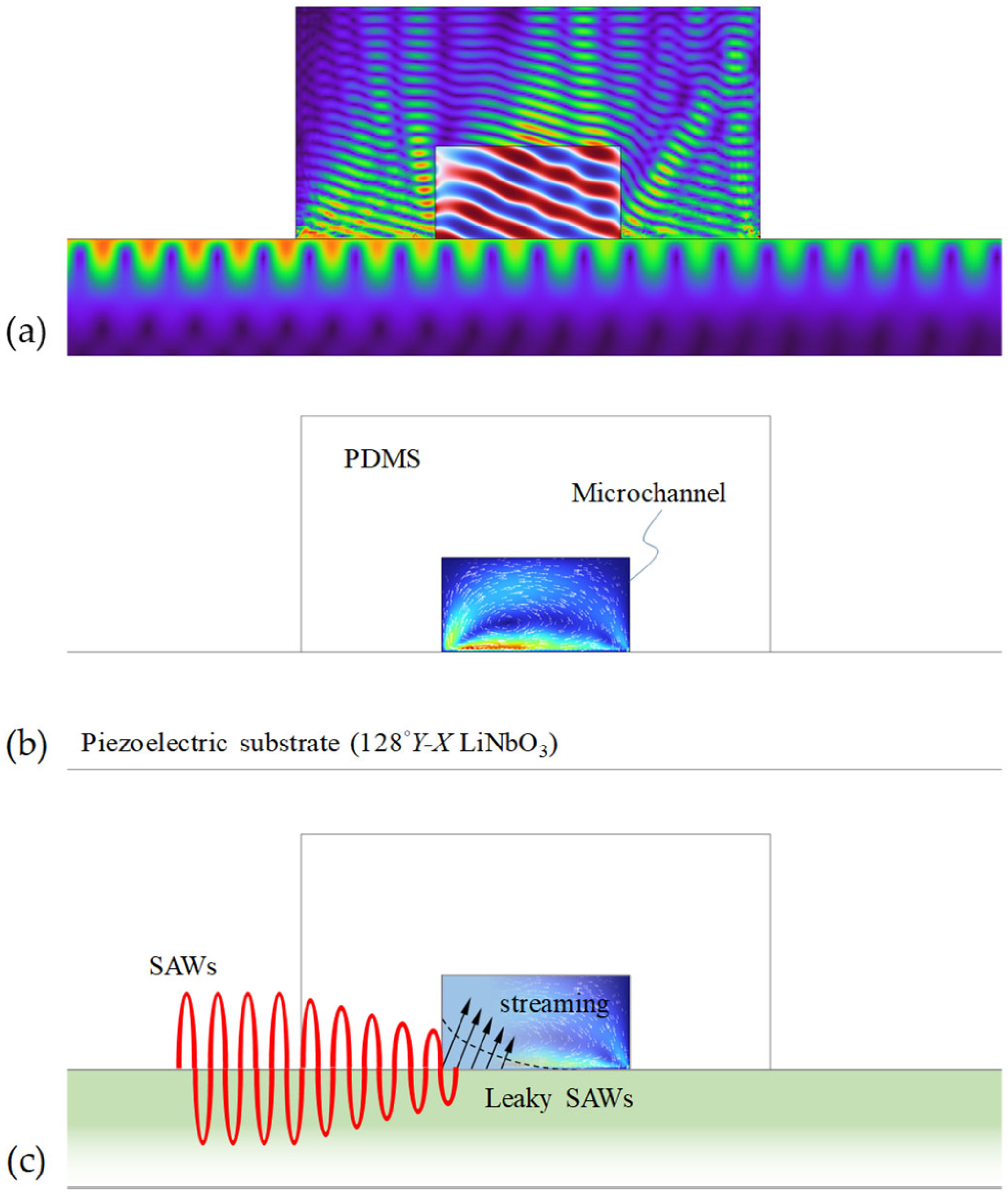
- Du, X.Y.; Swanwick, M.E.; Fu, Y.Q.; Luo, J.K.; Flewitt, A.J.; Lee, D.S.; Maeng, S.; Milne, W.I. Surface acoustic wave induced streaming and pumping in 128°Y-cut LiNbO3 for microfluidic applications. J. Micromech. Microeng. 2009, 19, 035016. [Google Scholar] [CrossRef]
- Mehmood, M.; Khan, U.F.; Maka, A.O.; Akhter, J.; Chaudhary, T.N.; Masood, F.; Hasan, S.A.; Lee, Y.C. A review of thermal impact of surface acoustic waves on microlitre droplets in medical applications. Adv. Mech. Eng. 2022, 14, 16878132221116481. [Google Scholar] [CrossRef]
- Dimotakis, P.E. The mixing transition in turbulent flows. J. Fluid Mech. 2000, 409, 69–98. [Google Scholar] [CrossRef]
- Capretto, L.; Cheng, W.; Hill, M.; Zhang, X. Micromixing within microfluidic devices. Top. Curr. Chem. 2011, 304, 27. [Google Scholar]
- Suh, Y.K.; Kang, S. A review on mixing in microfluidics. Micromachines 2010, 1, 82–111. [Google Scholar] [CrossRef]
- Ottino, J.M.; Wiggins, S. Designing optimal micromixers. Science 2004, 305, 485–486. [Google Scholar] [CrossRef]
- Yeo, L.Y.; Friend, J.R. Surface acoustic wave microfluidics. Annu. Rev. Fluid Mech. 2014, 46, 379–406. [Google Scholar] [CrossRef]
- Hashimoto, K.-Y. Surface Acoustic Wave Devices in Telecommunications; Springer: Berlin/Heidelberg, Germany, 2000. [Google Scholar]
- Auld, B.A. Acoustic Fields and Waves in Solids; R. E. Krieger: New York, NY, USA, 1990; Volume 1. [Google Scholar]
- Hsu, J.-C.; Chao, C.-L. Full-wave modeling of micro-acoustofluidic devices driven by standing surface acoustic waves for microparticle acoustophoresis. J. Appl. Phys. 2020, 128, 124502. [Google Scholar] [CrossRef]
- Royer, D.; Dieulesaint, E. Elastic Waves in Solids; Springer: Berlin/Heidelberg, Germany, 2000; Volume 1. [Google Scholar]
- Friend, J.; Yeo, L.Y. Microscale acoustofluidics: Microfluidics driven via acoustics and ultrasonics. Rev. Mod. Phys. 2011, 83, 647–704. [Google Scholar] [CrossRef]
- Gantner, A.; Hoppe, R.H.; Köster, D.; Siebert, K.; Wixforth, A. Numerical simulation of piezoelectrically agitated surface acoustic waves on microfluidic biochips. Comput. Vis. Sci. 2007, 10, 145–161. [Google Scholar] [CrossRef]
- Tan, M.K.; Friend, J.R.; Yeo, L.Y. Direct visualization of surface acoustic waves along substrates using smoke particles. Appl. Phys. Lett. 2007, 91, 224101. [Google Scholar] [CrossRef]
- Ingebrigtsen, K.A. Surface waves in piezoelectrics. J. Appl. Phys. 1969, 40, 2681–2686. [Google Scholar] [CrossRef]
- Hsu, J.-C.; Hsu, C.-H.; Huang, Y.-W. Acoustophoretic control of microparticle transport using dual-wavelength surface acoustic wave devices. Micromachines 2019, 10, 52. [Google Scholar] [CrossRef]
- Stringer, M.; Zeng, Z.; Zhang, X.; Chai, Y.; Li, W.; Zhang, J.; Ong, H.; Liang, D.; Dong, J.; Li, Y.; et al. Methodologies, technologies, and strategies for acoustic streaming-based acoustofluidics. Appl. Phys. Rev. 2023, 10, 011315. [Google Scholar] [CrossRef]
- Mazalan, M.B.; Noor, A.M.; Wahab, Y.; Yahud, S.; Zaman, W.S.W.K. Current development in interdigital transducer (IDT) surface acoustic wave devices for live cell in vitro studies: A review. Micromachines 2021, 13, 30. [Google Scholar] [CrossRef]
- Sun, X.; Ge, S.; Shao, X.; Zhou, S.; Wang, W.; Lin, D.; Liu, W. Analysis and design of single-phase unidirectional transducers with high directivity. Appl. Sci. 2021, 11, 7500. [Google Scholar] [CrossRef]
- Morgan, D.P. Quasi-static analysis of floating electrode unidirectional SAW transducers. IEEE Trans. Ultrason. Ferroelectr. Freq. Control. 2001, 48, 1289–1297. [Google Scholar] [CrossRef] [PubMed]
- Lei, Y.; Hu, H. SAW-driven droplet jetting technology in microfluidic: A review. Biomicrofluidics 2020, 14, 061505. [Google Scholar] [CrossRef] [PubMed]
- Yatsuda, H. Design techniques for SAW filters using slanted finger interdigital transducers. IEEE Trans. Ultrason. Ferroelectr. Freq. Control. 1997, 44, 453–459. [Google Scholar] [CrossRef] [PubMed]
- Zheng, T.; Liu, Y.; Xu, C.; Lu, H.; Wang, C. Focusing surface acoustic waves assisted electrochemical detector in microfluidics. Electrophoresis 2020, 41, 860–866. [Google Scholar] [CrossRef]
- Wu, T.-T.; Tang, H.-T.; Chen, Y.-Y. Frequency response of a focused SAW device based on concentric wave surfaces: Simulation and experiment. J. Phys. D Appl. Phys. 2005, 38, 2986. [Google Scholar] [CrossRef]
- Wu, T.-T.; Tang, H.-T.; Chen, Y.-Y.; Liu, P.-L. Analysis and design of focused interdigital transducers. IEEE Trans. Ultrason. Ferroelectr. Freq. Control. 2005, 52, 1384–1392. [Google Scholar]
- Nakagomi, S.; Asano, H.; Tanaka, H.; Omori, T.; Hashimoto, K.Y.; Yamaguchi, M. Single-phase unidirectional surface acoustic wave transducer using Cu electrode. Jpn. J. Appl. Phys. 2003, 42, 3152. [Google Scholar] [CrossRef]
- Rayleigh, L. On the circulation of air observed in Kundt’s tubes, and on some allied acoustical problems. Philos. Trans. R. Soc. Lond. 1884, 175, 2. [Google Scholar]
- Nyborg, W.L.M. Acoustic streaming. In Physical Acoustics; Academic Press: London, UK, 2024; Volume 2, pp. 265–331. [Google Scholar]
- Westervelt, P.J. The theory of steady rotational flow generated by sound field. J. Acoust. Soc. Am. 1965, 25, 60–67. [Google Scholar] [CrossRef]
- Alghane, M.; Chen, B.X.; Fu, Y.Q.; Li, Y.; Luo, J.K.; Walton, A.J. Experimental and numerical investigation of acoustic streaming excited by using a surface acoustic wave device on a 128°YX-LiNbO3 substrate. J. Micromech. Microeng. 2010, 21, 015005. [Google Scholar] [CrossRef]
- Lighthill, J. Acoustic streaming. J. Sound Vib. 1978, 61, 391–418. [Google Scholar] [CrossRef]
- Eckart, C. Vortices and streams caused by sound waves. Phys. Rev. 1948, 73, 68. [Google Scholar] [CrossRef]
- Schlichting, H. Berechnung ebener periodischer Grenzschichtstromungen. Phys. Zeit. 1932, 33, 327–335. [Google Scholar]
- Bradley, C.E. Acoustic streaming field structure: The influence of the radiator. J. Acoust. Soc. Am. 1996, 100, 1399–1408. [Google Scholar] [CrossRef]
- Riley, N. Steady streaming. Annu. Rev. Fluid Mech. 2001, 33, 43–65. [Google Scholar] [CrossRef]
- Muller, P.B.; Barnkob, R.; Jensen, M.J.H.; Bruus, H. A numerical study of microparticle acoustophoresis driven by acoustic radiation forces and streaming-induced drag forces. Lab A Chip 2012, 12, 4617–4627. [Google Scholar] [CrossRef]
- Nama, N.; Barnkob, R.; Mao, Z.; Kähler, C.J.; Costanzo, F.; Huang, T.J. Numerical study of acoustophoretic motion of particles in a PDMS microchannel driven by surface acoustic waves. Lab A Chip 2015, 15, 2700–2709. [Google Scholar] [CrossRef]
- Skov, N.R.; Sehgal, P.; Kirby, B.J.; Bruus, H. Three-dimensional numerical modeling of surface-acoustic-wave devices: Acoustophoresis of micro-and nanoparticles including streaming. Phys. Rev. Appl. 2019, 12, 044028. [Google Scholar] [CrossRef]
- Cai, S.; Jin, Y.; Lin, Y.; He, Y.; Zhang, P.; Ge, Z.; Yang, W. Micromixing within microfluidic devices: Fundamentals, design, and fabrication. Biomicrofluidics 2023, 17, 061503. [Google Scholar] [CrossRef]
- Hsu, J.-C.; Chang, C.-Y. Enhanced acoustofluidic mixing in a semicircular microchannel using plate mode coupling in a surface acoustic wave device. Sens. Actuators A Phys. 2022, 336, 113401. [Google Scholar] [CrossRef]
- Shilton, R.J.; Yeo, L.Y.; Friend, J.R. Quantification of surface acoustic wave induced chaotic mixing-flows in microfluidic wells. Sens. Actuators B Chem. 2011, 160, 1565–1572. [Google Scholar] [CrossRef]
- Shilton, R.J.; Travagliati, M.; Beltram, F.; Cecchini, M. Nanoliter-droplet acoustic streaming via ultrahigh frequency surface acoustic waves. Adv. Mater. 2014, 26, 4941. [Google Scholar] [CrossRef] [PubMed]
- Zhang, A.L.; Wu, Z.Q.; Xia, X.H. Transportation and mixing of droplets by surface acoustic wave. Talanta 2011, 84, 293–297. [Google Scholar] [CrossRef]
- Kishor, R.; Seah, Y.P.; Zheng, Y.J.; Xia, H.M.; Wang, Z.F.; Lu, H.J.; Lim, T.T. Characterization of an acoustically coupled multilayered microfluidic platform on SAW substrate using mixing phenomena. Sens. Actuators A Phys. 2015, 233, 360–367. [Google Scholar] [CrossRef]
- Ahmed, H.; Park, J.; Destgeer, G.; Afzal, M.; Sung, H.J. Surface acoustic wave-based micromixing enhancement using a single interdigital transducer. Appl. Phys. Lett. 2019, 114, 043702. [Google Scholar] [CrossRef]
- Cha, B.; Kim, W.; Yoon, G.; Jeon, H.; Park, J. Enhanced solutal Marangoni flow using ultrasound-induced heating for rapid digital microfluidic mixing. Front. Phys. 2021, 9, 735651. [Google Scholar] [CrossRef]
- Shilton, R.; Tan, M.K.; Yeo, L.Y.; Friend, J.R. Particle concentration and mixing in microdrops driven by focused surface acoustic waves. J. Appl. Phys. 2008, 104, 014910. [Google Scholar] [CrossRef]
- Luong, T.D.; Phan, V.N.; Nguyen, N.T. High-throughput micromixers based on acoustic streaming induced by surface acoustic wave. Microfluid. Nanofluidics 2011, 10, 619–625. [Google Scholar] [CrossRef]
- Zeng, Q.; Guo, F.; Yao, L.; Zhu, H.W.; Zheng, L.; Guo, Z.X.; Liu, W.; Chen, Y.; Guo, S.S.; Zhao, X.Z. Milliseconds mixing in microfluidic channel using focused surface acoustic wave. Sens. Actuators B Chem. 2011, 160, 1552–1556. [Google Scholar] [CrossRef]
- Destgeer, G.; Im, S.; Hang Ha, B.; Ho Jung, J.; Ahmad Ansari, M.; Jin Sung, H. Adjustable, rapidly switching microfluidic gradient generation using focused travelling surface acoustic waves. Appl. Phys. Lett. 2014, 104, 023506. [Google Scholar] [CrossRef]
- Nam, J.; Jang, W.S.; Lim, C.S. Micromixing using a conductive liquid-based focused surface acoustic wave (CL-FSAW). Sens. Actuators B Chem. 2018, 258, 991–997. [Google Scholar] [CrossRef]
- Lim, H.; Back, S.M.; Choi, H.; Nam, J. Acoustic mixing in a dome-shaped chamber-based SAW (DC-SAW) device. Lab A Chip 2020, 20, 120–125. [Google Scholar] [CrossRef] [PubMed]
- Zhang, Y.; Devendran, C.; Lupton, C.; De Marco, A.; Neild, A. Versatile platform for performing protocols on a chip utilizing surface acoustic wave (SAW) driven mixing. Lab A Chip 2019, 19, 262–271. [Google Scholar] [CrossRef] [PubMed]
- Frommelt, T.; Kostur, M.; Wenzel-Schäfer, M.; Talkner, P.; Hänggi, P.; Wixforth, A. Microfluidic mixing via acoustically driven chaotic advection. Phys. Rev. Lett. 2008, 100, 034502. [Google Scholar] [CrossRef]
- Westerhausen, C.; Schnitzler, L.G.; Wendel, D.; Krzysztoń, R.; Lächelt, U.; Wagner, E.; Rädler, J.O.; Wixforth, A. Controllable acoustic mixing of fluids in microchannels for the fabrication of therapeutic nanoparticles. Micromachines 2016, 7, 150. [Google Scholar] [CrossRef]
- Tseng, W.K.; Lin, J.L.; Sung, W.C.; Chen, S.H.; Lee, G.B. Active micro-mixers using surface acoustic waves on Y-cut 128 LiNbO3. J. Micromech. Microeng. 2006, 16, 539. [Google Scholar] [CrossRef]
- Jo, M.C.; Guldiken, R. Dual surface acoustic wave-based active mixing in a microfluidic channel. Sens. Actuators A Phys. 2013, 196, 1–7. [Google Scholar] [CrossRef]
- Nam, J.; Lim, C.S. Micromixing using swirling induced by three-dimensional dual surface acoustic waves (3D-dSAW). Sens. Actuators B Chem. 2018, 255, 3434–3440. [Google Scholar] [CrossRef]
- Biroun, M.H.; Rahmati, M.; Jangi, M.; Chen, B.; Fu, Y.Q. Numerical and experimental investigations of interdigital transducer configurations for efficient droplet streaming and jetting induced by surface acoustic waves. Int. J. Multiph. Flow 2021, 136, 103545. [Google Scholar] [CrossRef]
- Zheng, T.; Liu, Y.; Fu, Y.; Wang, C. Asymmetrically aligned focused acoustic waves for enhancing sensing performance of electrochemical microarrays. Appl. Phys. Lett. 2023, 122, 243702. [Google Scholar] [CrossRef]
- Hsu, J.-C.; Liao, K.-L. Microfluidic mixing driven by dual eccentrically focused surface acoustic waves. Sens. Actuators A Phys. 2025, 390, 116600. [Google Scholar] [CrossRef]
- Kulkarni, K.; Friend, J.; Yeo, L.; Perlmutter, P. Surface acoustic waves as an energy source for drop scale synthetic chemistry. Lab A Chip 2009, 9, 754–755. [Google Scholar] [CrossRef] [PubMed]
- Kim, S.; Nam, H.; Cha, B.; Park, J.; Sung, H.J.; Jeon, J.S. Acoustofluidic stimulation of functional immune cells in a microreactor. Adv. Sci. 2022, 9, 2105809. [Google Scholar] [CrossRef] [PubMed]
- Bai, C.; Zhou, W.; Yu, S.; Zheng, T.; Wang, C. A surface acoustic wave-assisted micromixer with active temperature control. Sens. Actuators A Phys. 2022, 346, 113833. [Google Scholar] [CrossRef]
- Winkler, A.; Brünig, R.; Faust, C.; Weser, R.; Schmidt, H. Towards efficient surface acoustic wave (SAW)-based microfluidic actuators. Sens. Actuators A Phys. 2016, 247, 259–268. [Google Scholar] [CrossRef]


| Type | Example Techniques | Mixing Efficiency | Mixing Time | Mixing Length | Potential Pros and Cons |
|---|---|---|---|---|---|
| Passive | Split and recombination | 80–99% | - | 103–105 μm | No power supply required; Longer channels; Complex channel geometries; Expensive 3D channels |
| Surface patterning | |||||
| Hydrodynamic focusing | |||||
| Serpentine channel | |||||
| Obstacles in flow | |||||
| Active | Acoustic | 80–99% | 10–3–101 s | - | External power supply required; Simpler channel geometries; Rapid and controllable mixing; Labeled fluids |
| Electrical | |||||
| Magnetic | |||||
| Pressure | |||||
| Thermal |
| Technique | Advantages | Limitation | Key to Improvement |
|---|---|---|---|
| Acoustic | Rapid mixing; easy operation; direct mechanical force | Low throughput; high cost; high power consumption | Improve mixing performance by enhancing fluid-structure interaction |
| Electrical | Efficiently used at low voltages; effective for short mixing lengths | Requires integrated electrodes and conductive liquids | Reduce the influence and dependence on conductive liquids |
| Magnetic | Efficient mixing with precise control; versatile | Requires magnetic materials or magnetic labels in samples/reagents | Enhance magnetic field strength for microscale applications |
| Pressure | Easy to implement using micropumps or electric fields | Requires fine-tuning for optimal mixing | Optimize operating pulsation parameters driven by the integrated pumps |
| Thermal | Easy to integrate into the microfluidic devices | Requires heaters; heating effects on samples/reagents | Reduce heating influences on samples/reagents |
| Design | Microfluidic Type | Acoustic Field and Frequency | Power Source | Flow Rate/Fluid Vol. | Mixing Efficiency | Ref. |
|---|---|---|---|---|---|---|
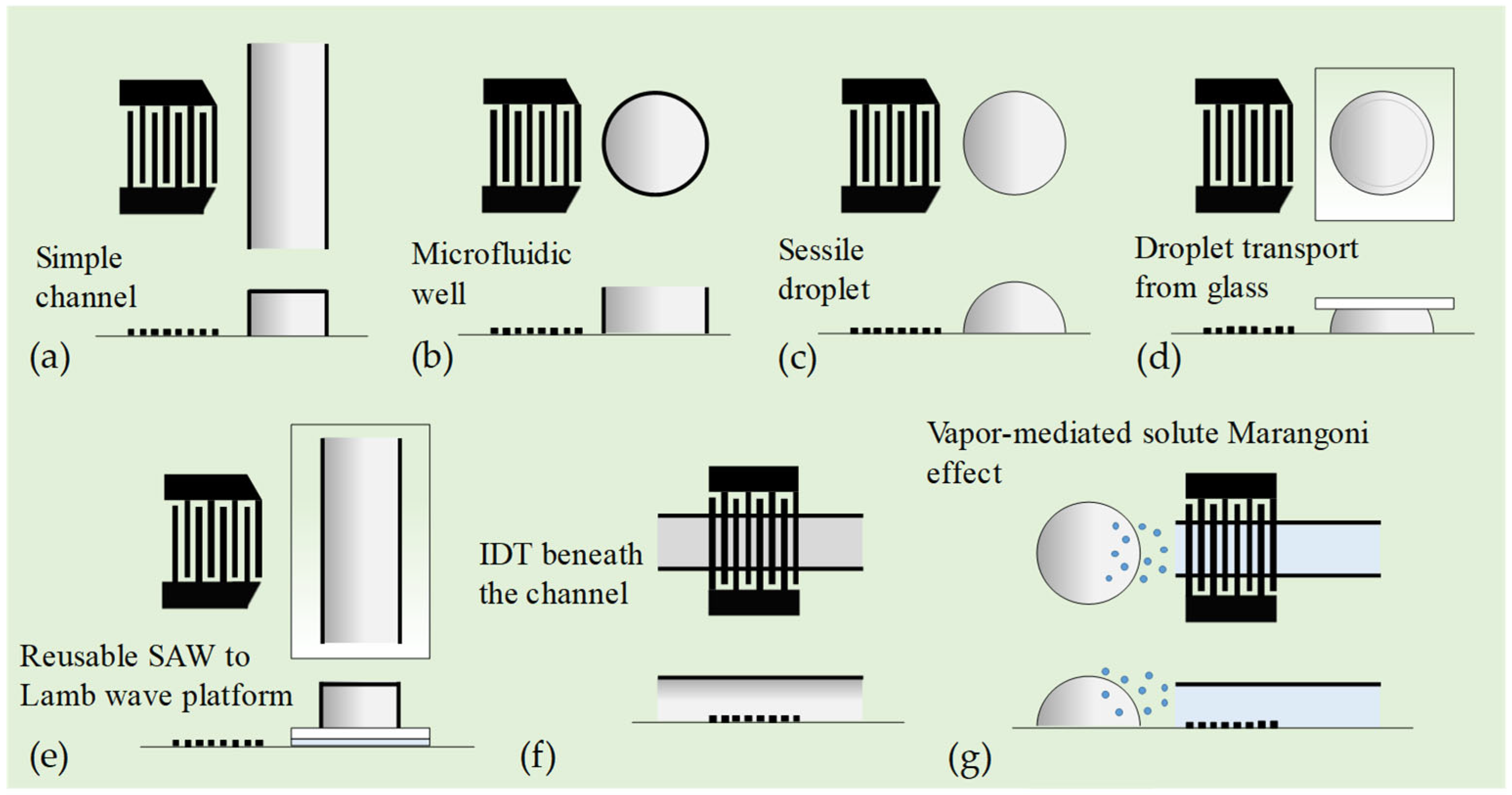
| Straight IDT | Channel flow | SAW and APW, 10 MHz | 30 dBm | 20 μL/min | - | [94] |
| Fluid well | SAW, 20 MHz | <1.6 W | 2.5 μL | - | [95] | |
| Sessile droplet | SAW, 47.8–1107 MHz | - | 0.6–58 nL | - | [96] | |
| Confined droplet | SAW, 27.5 MHz | 28.5 dBm | 2 μL | - | [97] | |
| Channel flow | SAW to Lamb wave, 50 and 100 MHz | 50 V | 1 μL/min | 80% | [98] | |
| Channel flow | SAW, 140 MHz | 12 V | 50 μL/min | ~100% | [99] | |
| Sessile droplet | SAW, 29 MHz | 0.5 W | 2 μL | ~100% | [100] | |
| Non-straight IDT | Sessile droplet | Focused SAW, 30 MHz | <1 W | 2 μL | - | [101] |
| Channel flow | Focused SAW, 13 MHz | 80 V | 10 mL/h | 88% | [102] | |
| Channel flow | Focused SAW, 19.29 MHz | 25 V | 2700 μm/s | - | [103] | |
| Channel flow | Focused SAW, 133.3 MHz | 0–17.9 V | 1100 μL/h | - | [104] | |
| Channel flow | Focused SAW, 9.2 MHz | 21 V | <120 μL/min | >90% | [105] | |
| Channel flow | Focused SAW, 39.6 MHz | 20 V | <300 μL/min | >90% | [106] | |
| Chamber | Focused SAW, 48.75, 70.9, and 130 MHz | 28 dBm | 44.3, 153 nL | - | [107] | |
| Channel flow | SAW excited by a SFIT, 79.5–82.5 MHz | 25 dBm | 0.2 mL/h | ~100% | [109] | |
| Multiple IDTs | Channel flow | Dual SAW, 9.6 MHz | 35 V | 513 μm/s | 94% | [110] |
| Channel flow | Dual SAW, 13.3 MHz | 85 V | 10 μL/min | 96.7% | [111] | |
| Channel flow | 3D dual focused SAW, 30 MHz | <18 V | <120 μL/min | >90% | [112] | |
| Sessile droplet | Offset dual SAW, 66.2 MHz | 12 W | 2 μL | - | [113] | |
| Fluid well | Asymmetrically aligned focused SAW, 19.3 MHz | 15 V | 40 μL | - | [114] | |
| Channel flow | Dual eccentrically focused SAW, 9.65 MHz | 12.5 V | 7 μL/min | 96% | [115] |
| IDT Design | Structure Characteristics | Application | Ref. |
|---|---|---|---|
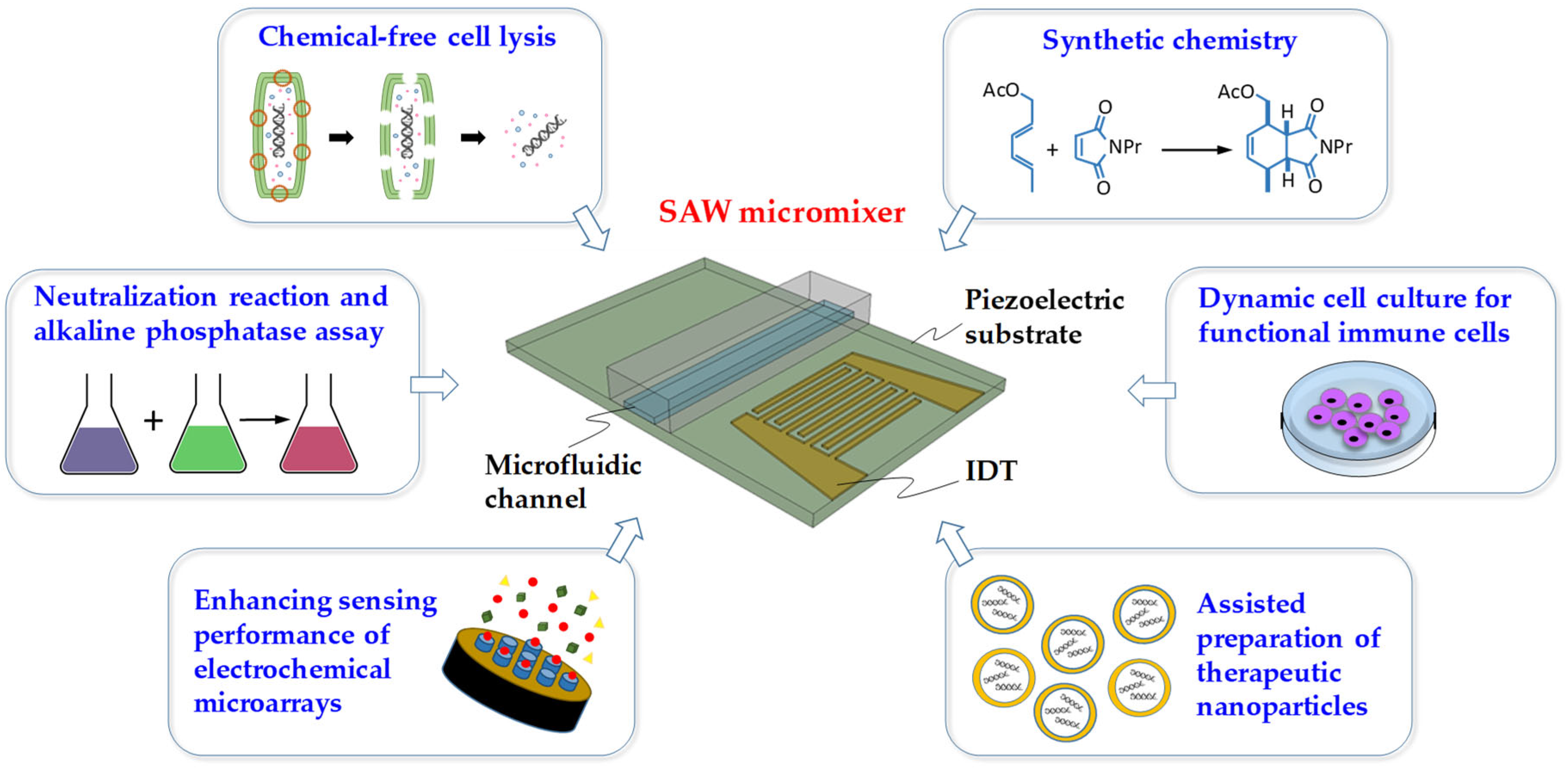
| Two straight IDTs | A 40 mL drop of reaction mixture on a piezoelectric substrate with IDTs at either end of the device connected to a power source. | Synthetic chemistry | [116] |
| An SFIT | Two equal-sized inlets of the Y-shaped elastomeric microchannel converge into a rectangular main channel with a width of 200 μm. The IDT is patterned on one side of the channel. | Assisted preparation of therapeutic nanoparticles | [109] |
| A straight IDT | A microreactor system including an open-top fluid well and an IDT on a LiNbO3 substrate. | Dynamic cell culture for functional immune cells | [117] |
| A focused IDT | Microchannel with integrated temperature control unit, which consists of a temperature sensor under the microchannel and a Peltier cooler under the microchip. | Neutralization reaction and alkaline phosphatase assay | [118] |
| Two focused IDTs | Two focused IDTs are asymmetrically distributed on both sides of a ring structure (a fluid well), producing two focused SAWs propagating in opposite directions, which generate acoustic streaming. | Enhancing the sensing performance of electrochemical microarrays | [114] |
| A straight IDT | The device comprises a piezoelectric LiNbO3 substrate with Cr/Au patterned IDT, and a SiO2 layer is deposited on the substrate to protect the electrodes. A straight microchannel with two serial inlets and one outlet was bonded to the substrate. | Chemical-free cell lysis | [100] |
Disclaimer/Publisher’s Note: The statements, opinions and data contained in all publications are solely those of the individual author(s) and contributor(s) and not of MDPI and/or the editor(s). MDPI and/or the editor(s) disclaim responsibility for any injury to people or property resulting from any ideas, methods, instructions or products referred to in the content. |
© 2025 by the author. Licensee MDPI, Basel, Switzerland. This article is an open access article distributed under the terms and conditions of the Creative Commons Attribution (CC BY) license (https://creativecommons.org/licenses/by/4.0/).
Share and Cite
Hsu, J.-C. Enhanced Micromixing Using Surface Acoustic Wave Devices: Fundamentals, Designs, and Applications. Micromachines 2025, 16, 619. https://doi.org/10.3390/mi16060619
Hsu J-C. Enhanced Micromixing Using Surface Acoustic Wave Devices: Fundamentals, Designs, and Applications. Micromachines. 2025; 16(6):619. https://doi.org/10.3390/mi16060619
Chicago/Turabian StyleHsu, Jin-Chen. 2025. "Enhanced Micromixing Using Surface Acoustic Wave Devices: Fundamentals, Designs, and Applications" Micromachines 16, no. 6: 619. https://doi.org/10.3390/mi16060619
APA StyleHsu, J.-C. (2025). Enhanced Micromixing Using Surface Acoustic Wave Devices: Fundamentals, Designs, and Applications. Micromachines, 16(6), 619. https://doi.org/10.3390/mi16060619