2.3. Thin-Film Thermocouple Performance Studies
In order to test the accuracy of the output signals of the developed TFTC temperature sensor and the commercially proven K-type wire thermocouple in the same environment, a static calibration was carried out. The static calibration system mainly includes heat source equipment and collection equipment. The heat source equipment is used to provide a stable temperature field for the thermocouples, and is also selected to provide a stable room temperature as the cold end for thermocouple temperature compensation. The acquisition equipment is then used to collect the thermal potential generated by the thermocouple in the loop. In order to ensure accuracy and comparability, the K-type wire thermocouple were static calibrated along with self-prepared film thermocouples.
To assess the accuracy of the output signals of the newly developed TFTC temperature sensor and the commercially validated K-type wire thermocouple within the same environment, a static calibration procedure was conducted. The static calibration system primarily consists of heat source equipment and data acquisition equipment. The heat source equipment serves to create a stable temperature field for the thermocouples, and also provides a consistent room temperature to act as the cold end for compensating the thermocouple temperatures. Subsequently, the acquisition equipment is utilized to gather the thermal potential generated within the thermocouple loop. To ensure precision and comparability, the K-type wire thermocouple was calibrated statically alongside the self-made TFTC.
In this study, the HANBANG electronic HP-E1515 constant temperature heating station was employed as the hot end of the static calibration system. Capable of setting temperatures up to 400 °C, this heating station can directly achieve intelligent and stable temperature control via its internal CPU. It also offers an intuitive display of the set temperature. Moreover, its user-friendly and convenient operation streamlines the calibration process, and make it more efficient.
- 2.
Acquisition equipment.
The RIGOL DM3068 six-and-a-half-digit desktop digital multimeter (RIGOL Technologies, Co. Ltd. Beijing, China) was selected as the acquisition device for measuring the thermal potential of the TFTC. Renowned for its high precision, it boasts a maximum measurement rate of 10 Krdgs/s. Integrating functions such as automatic measurement and various digital conversions, it is both easy to operate and highly flexible.
Specifically, as illustrated in
Figure 6, the hot end of the thermocouple was attached to the center of the thermostatic heating table, while the cold end was placed directly in the air at a constant temperature. The digital multimeter was then used to record the thermal potential. To obtain a more reliable Seebeck coefficient for the TFTC, the temperature range of the heat source constant temperature heating table was set from 50 °C to 400 °C. The cold end was maintained at room temperature. Thus, the static calibration temperature was calculated as the temperature of the constant temperature heating table minus the room temperature. With the current room temperature at 15 °C, the actual static calibration temperature range was from 35 °C to 385 °C. To ensure temperature stability, the temperature of the constant temperature heating table was allowed to stabilize for 5 min for every 5 °C increase. The thermal potential was then recorded at different static calibration temperatures. Given that the commercial K-type wire thermocouple, due to its tape encapsulation, can only measure temperatures up to a maximum of 215 °C, the actual static calibration temperature range for this thermocouple was adjusted to be from 35 °C to 200 °C.
Based on the above principle of Seebeck effect, the expression for temperature versus voltage during static calibration is
describes the thermopotential of the thermocouple.
is the measured temperature.
denotes the Seebeck coefficient, which represents the voltage generated per degree Celsius of temperature difference.
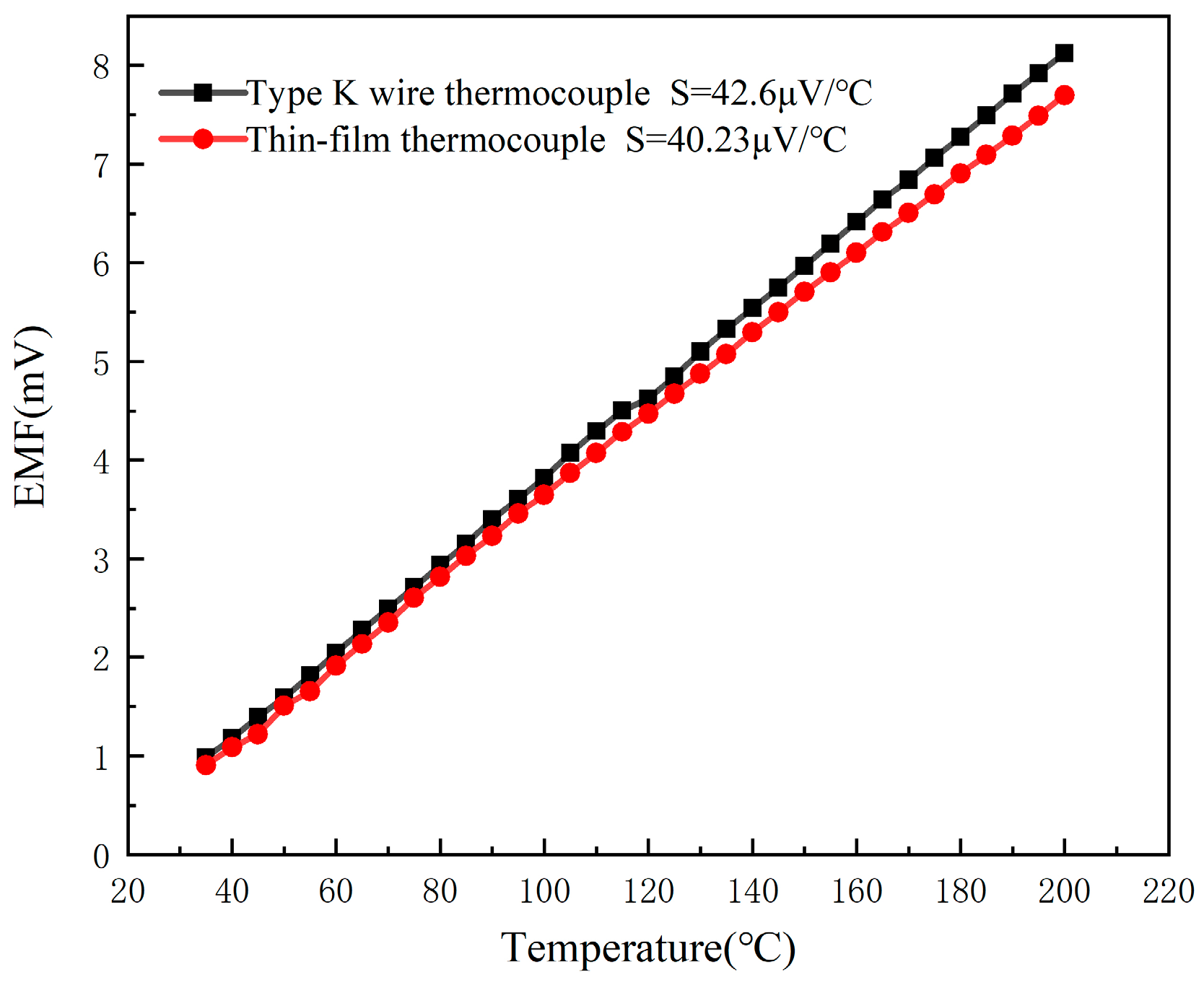
is the intercept term used to correct for the baseline voltage offset at 0 °C. The static calibration thermopotential–temperature relationship for the K-type wire thermocouple and the developed TFTC is shown in
Figure 7. The data generated from the static calibration experiments were analyzed by Origin 2018 analysis software, and the static calibration curves, fitting equations, correlation coefficients, and nonlinear fitting errors for the developed K-type wire thermocouple and the TFTC are derived by using the least squares method. The fitting equation for the output thermopotential E of a K-type wire thermocouple for temperature measurement to the static calibration temperature is:
, and the Seebeck coefficient S is 42.6 μV/°C. The fitting equation for the output thermopotential E of the TFTC temperature measurement to the static calibration temperature is:
, the Seebeck coefficient S is 40.23 μV/°C. Although the Seebeck coefficients of the two are close, the value of the TFTC is slightly smaller than that of the K-type wire thermocouple. This difference is mainly due to the fact that electrons within the positive NiCr thin film in the TFTC can only enter the NiSi thin film through the overlapping region of the thin film. Due to the limitation of film thickness, the positive film cannot provide enough free electrons to effectively transition to the negative film, so at the same temperature, the Seebeck coefficient of the TFTC is less than that of the K-type wire thermocouple [
23].
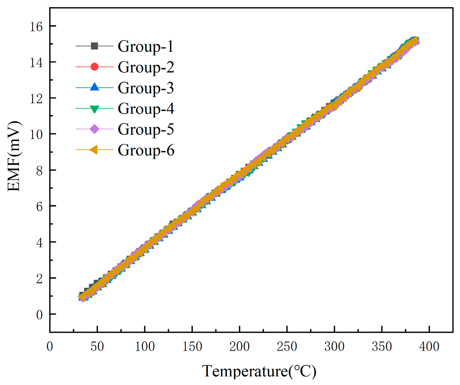
In order to test the accuracy and repeatability of the output signals of the developed TFTC temperature sensor and K-type wire thermocouple in the same environment, the repeatability test of the TFTC was made on the basis of the above static calibration. The same TFTC was tested for six times by using the above static calibration method, and the curves of these six repetitions are shown in
Figure 8.
The data from the above six experiments were analyzed for repeatability error and the standard deviation was calculated as
where n represents the actual number of measurements,
is the result of each measurement,
is the average of multiple measurements and σ is the standard deviation.
After calculating the standard deviation, calculate the repeatability error based on this to evaluate the stability of the film thermocouple. The repeatability error is calculated as
where
is the repeatability error.
is the average of multiple measurements and σ is the standard deviation.
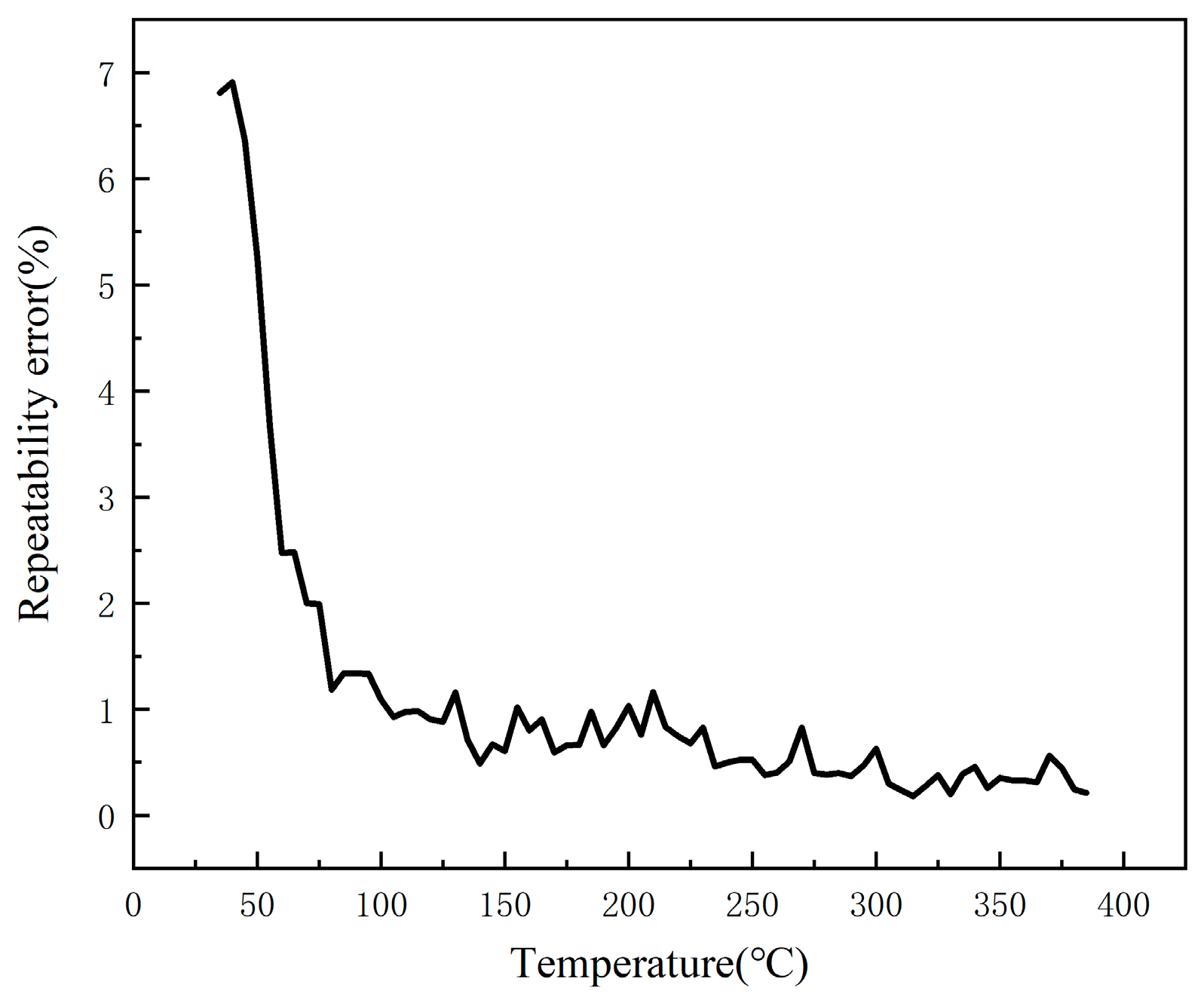
In
Figure 9, it can be seen that, when the temperature is 35 °C, the sensor repeatability error is the largest, 6.81%, with the gradual increase in temperature, the repeatability error gradually decreases, and finally stabilized at 0.3%.
In conclusion, the developed film thermocouple Seebeck coefficient is large, high temperature measurement accuracy, error within a reasonable range, good repeatability, can be realized in the use of the process of repeated accurate temperature measurement.
2.4. Introduction to IGBT Modules
SGT40N6ONPFDPN insulated gate bipolar transistor (40N60IGBT) using a new generation of field stop (Field Stop) process, is a modular semiconductor products from the insulated gate bipolar transistor and FWD (current–supply diode chip) through the specific circuit bridging package, with a low on-state loss and switching loss, a positive temperature coefficient is easy for parallel applications. The low conduction loss and switching loss, positive temperature coefficient and easy parallel application are some of the features.
The 40N60IGBT power electronic module of the overall loss generated by the insulated gate bipolar transistor and the FWD of their respective losses and, therefore, in the work of the cause of its heating there are three reasons, one is the conduction of the on-state loss (Ploss_on), the second is the switching loss generated in the process of turning on and off, and the third is the clogging loss, but due to the clogging loss is relatively small, usually can be ignored [
26]. This paper focuses on the pass-state loss and switching loss of IGBT modules. Due to its own on-state voltage drop is not zero, so the pass-state loss is generated, IGBT unit pass-state loss formula is
where
is the zero-current conduction state collector-emitter voltage,
is the collector-emitter resistance,
is the average value of the current,
is the rms value of the current,
is the output current, and
is the duty cycle.
The IGBT cell switching loss equation is
where
is the switching frequency;
is the turn-on loss;
is the turn-off loss.
For the FWD chip, the pass-state power consumption is
where
is the on-state voltage drop,
is the on-state resistance,
is the average value of current,
is the rms value of current,
is the output current, and
is the duty cycle.
The switching power consumption is
where
is the switching frequency,
is the turn-on loss.
The total power consumption of the IGBT chip is
The total power consumption of the FWD chip is
The total loss of the 40N60 IGBT power electronics module is equal to the sum of the total power consumption of the IGBT chip and the total power consumption of the FWD chip, which is
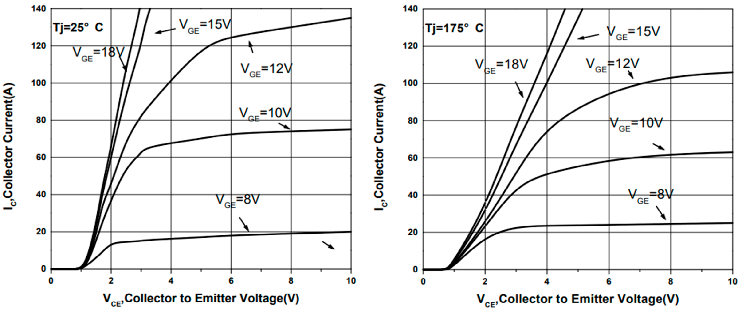
and
and the voltages can be obtained by consulting the 40N60IGBT chip manual and combining them with the operating currents, as shown in
Figure 10.
As a high-power semiconductor device, the overall performance and reliability of IGBT modules are influenced by temperature. From a macro point of view, is simply due to the high power loss, IGBT will produce more heat. From a micro perspective, the essence of heat generation is the reduction in kinetic energy of electrons during flow, which is lost in the form of heat energy. Given that the junction temperature of the IGBT cannot exceed 175 °C, and should not be operated at higher temperatures for a long period of time, temperature monitoring of the IGBT module is essential. In order to realize the temperature monitoring of the IGBT module, in this paper, the above calibrated film thermocouple and silk thermocouple are laminated on the surface of 40N60IGBT in TO-247 package. By allowing the 40N60IGBT to function properly in the circuit, these two thermocouples together form a thin-film thermocouple-based IGBT chip surface temperature test system. When actually monitoring the junction temperature, it is necessary to combine the circuit, power consumption and thermal resistance to calculate the accurate junction temperature in the chip.
2.5. Construction of IGBT Module Temperature Test System Based on Thin-Film Thermocouple
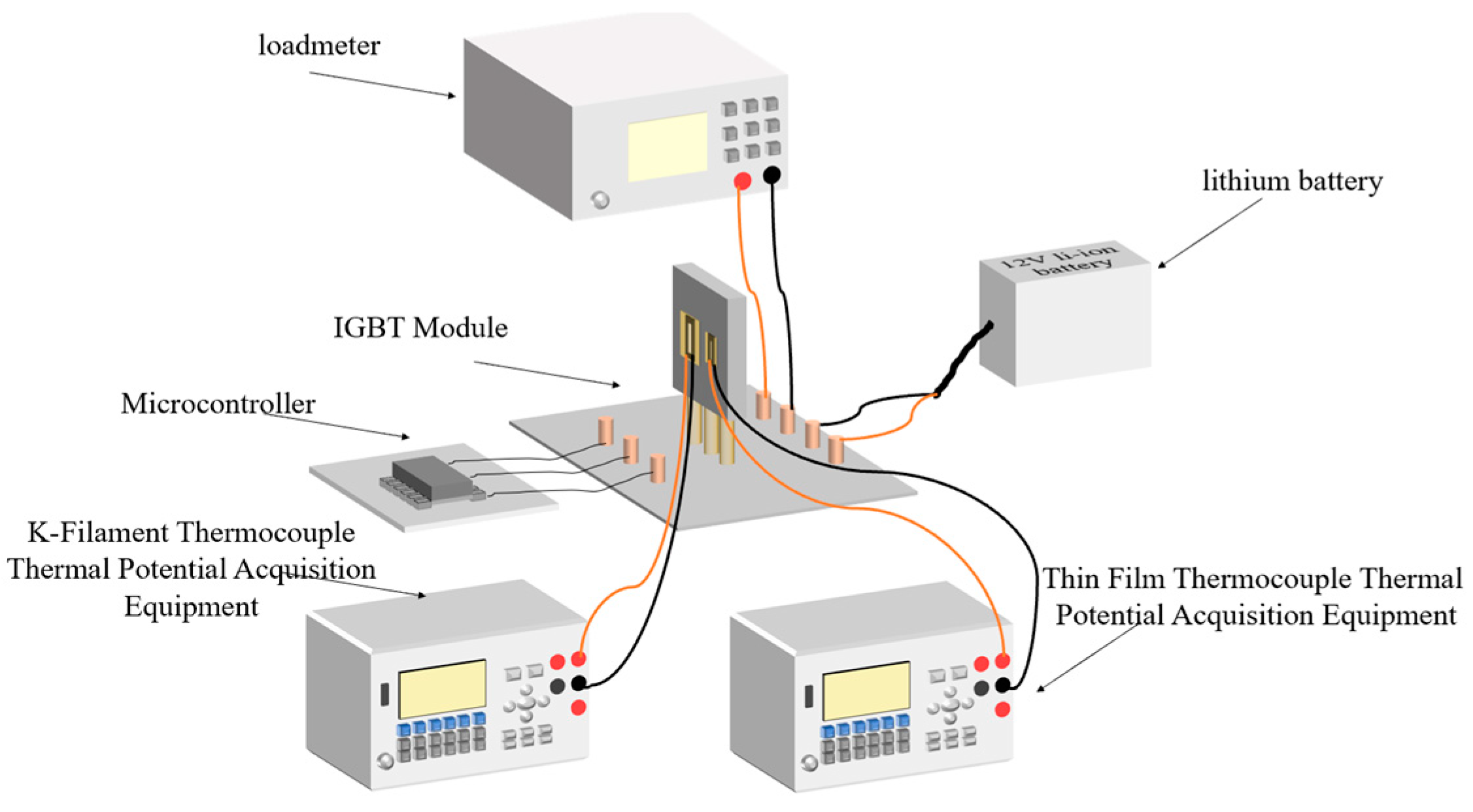
The 40N60IGBT temperature measurement system mainly includes: a 40N60IGBT working system, film thermocouple, K-type wire thermocouple, and voltage acquisition equipment.
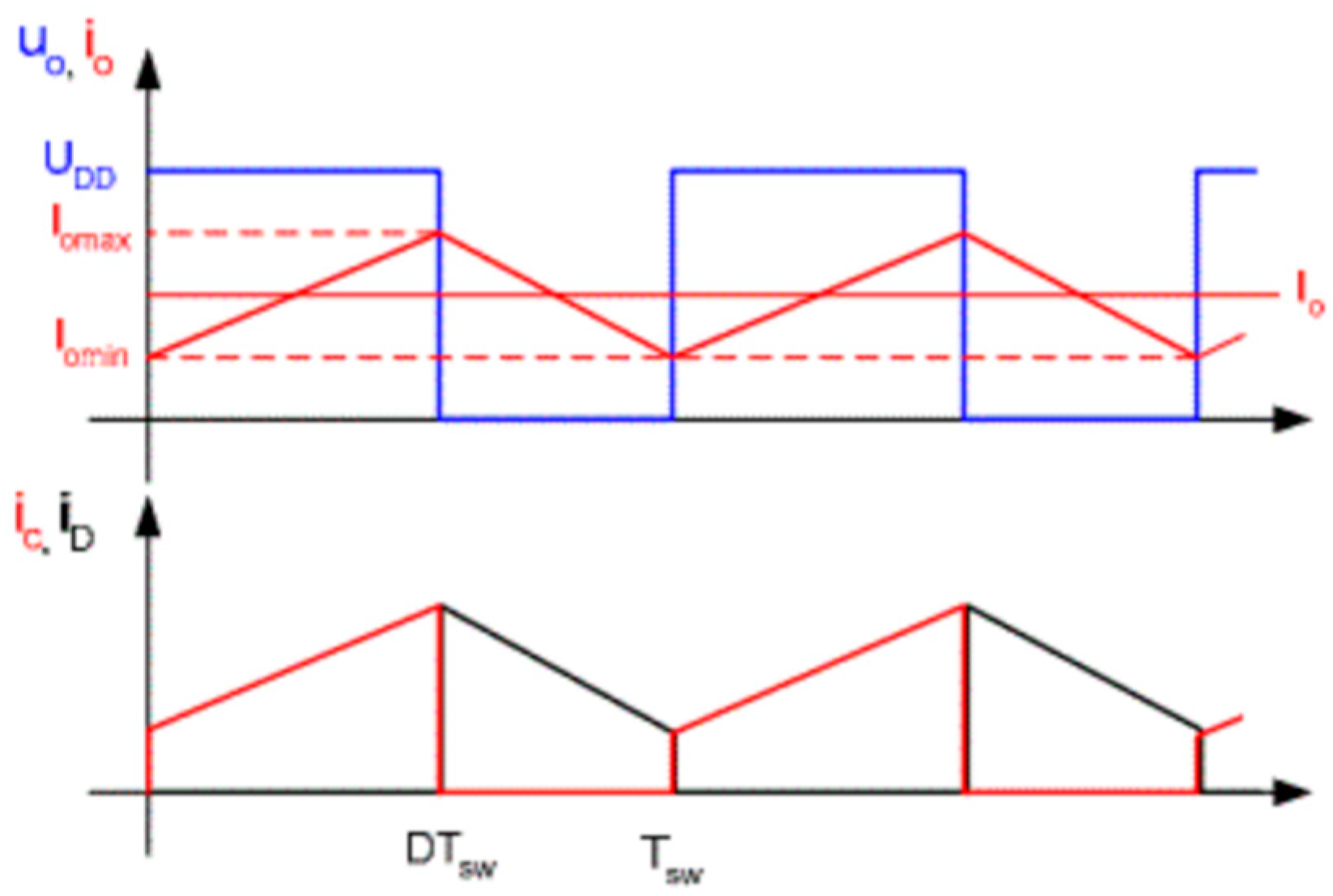
In this paper, the test 40N60IGBT operating system is through the microcontroller output control signals, switching load circuits, and in the middle of adding optocoupler isolation circuit to prevent interference. The entire load circuit is powered by a 12 V lithium polymer battery, and the output is directly connected to the load, which has Ainuo DC electronic load AN23103H devices and gold aluminum case high-power resistors; for different experimental variables, you need to adjust different output loads, easy to observe and set the output power and output current. For the experimental setup, a typical signal for a purely resistive load driver module is shown in
Figure 11. The curve in the figure is represented by the logo of the same color in the upper left corner of the central axis.
- 2.
Temperature measuring film.
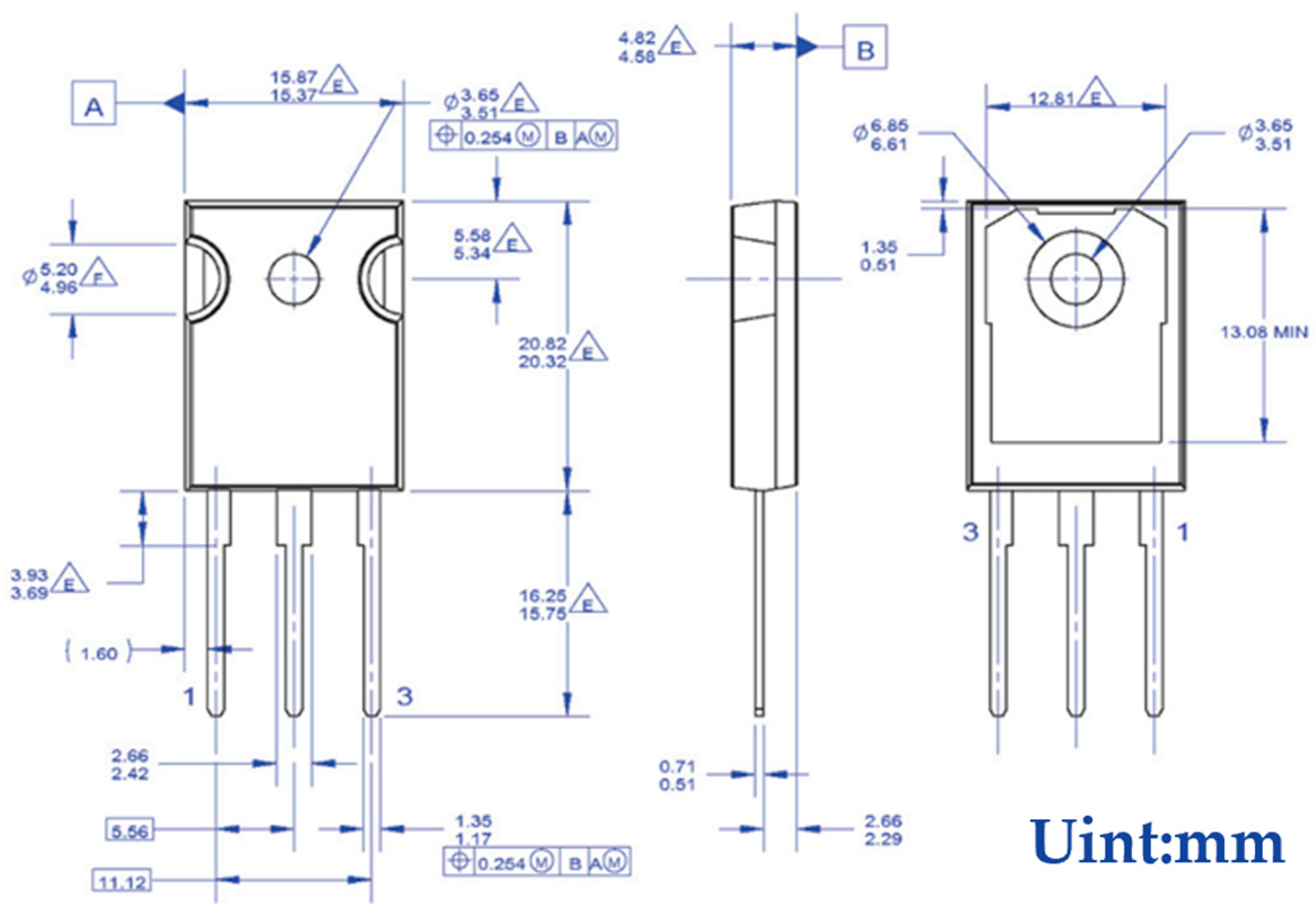
The SGT40N6ONPFDPN is packaged in a TO-247 package with specific dimensions, as shown in
Figure 12. The length and width are larger than those of the self-designed film thermocouple, which makes it easy to stick the film thermocouple on its surface. During the experiment, the self-designed and calibrated film thermocouples and K-type wire thermocouples are pasted on the surface of the 40N60IGBT, which is convenient to accurately sense the temperature change.
- 3.
Voltage acquisition equipment.
The selected Puyuan DM3068 six and a half desktop digital multimeter is close to the surface of the IGBT module of the film thermocouple temperature measurement of the thermal potential of the acquisition of equipment, and calibration experiments with the use of equipment consistent with the acquisition of the trigger form is set to the external trigger; the input of a 2 Hz square wave was attached to the external trigger pin of the multimeter, and we set the delay time of 0.5 s to collect the voltage once.

