Article

A Si/SiC Heterojunction Double-Trench MOSFET with Improved Conduction Characteristics

1
School of Electrical Engineering, Southwest Jiaotong University, Chengdu 611756, China
2
School of Integrated Science and Engineering, Southwest Jiaotong University, Chengdu 611756, China
3
School of Science, Xihua University, Chengdu 610039, China
*
Author to whom correspondence should be addressed.
Micromachines 2025, 16(12), 1335; https://doi.org/10.3390/mi16121335
Submission received: 29 October 2025 / Revised: 17 November 2025 / Accepted: 18 November 2025 / Published: 27 November 2025

Abstract

A Si/SiC heterojunction double-trench MOSFET with improved conduction characteristics is proposed. By replacing the N+ source and P-ch regions with silicon, the device forms a Si/SiC heterojunction that exhibits Schottky-like characteristics, effectively deactivating the parasitic PiN body diode and improving third-quadrant performance. A high-k gate dielectric is incorporated to induce a strong electron accumulation layer at the heterointerface, thinning the energy barrier and enabling tunneling-dominated current transport, thereby significantly enhancing the first-quadrant performance. TCAD simulation results demonstrate that the proposed device achieves a specific on-resistance (Ron,sp) of 1.78 mΩ·cm2, representing a 20.5% reduction compared to the conventional SiC DTMOS, while maintaining a comparable breakdown voltage (BV) of approximately 1380 V. A significant reduction in the third-quadrant turn-on voltage (Von) is achieved with the proposed structure, from 2.74 V to 1.53 V. Meanwhile, the unipolar conduction mechanism similar to that of Schottky effectively suppresses bipolar degradation. To enhance device reliability, the design incorporates a trenched source and heavily doped P-well, which collectively mitigate high electric field concentrations at the trench corners. The proposed device offers an integration strategy enhancing both forward conduction and reverse conduction in high-voltage power electronics.

1. Introduction

Silicon carbide (SiC) MOSFETs are highly competitive for medium- and high-voltage power electronics due to the superior material properties of SiC, including its wide bandgap, high critical breakdown field, and excellent thermal conductivity [1,2,3]. These characteristics make it a promising candidate for next-generation power switching devices.
However, SiC MOSFETs still face several critical technological challenges, particularly at the SiO2/SiC interface, where high interface state density causes strong carrier scattering [4,5,6,7,8]. Despite extensive research, the channel mobility in SiC MOSFETs remains approximately one order of magnitude lower than that of silicon-based devices and far below the bulk mobility of SiC [5,9,10]. This low mobility directly results in high channel resistance. To overcome this limitation, the Si/SiC VDMOS heterostructure has been introduced [11]. It leverages the superior channel mobility of silicon to effectively reduce Ron,sp [12]. Recent investigations have further developed this concept. Chen, H. et al. demonstrated a Si/4H-SiC VDMOS incorporating an electron tunneling layer, which substantially lowers on-state resistance by facilitating electron tunneling through a narrowed heterojunction barrier [13]. Wang et al. proposed a triple RESURF Si/SiC heterojunction LDMOS complete with an analytical model [14]. The practical implementation of these heterojunction devices relies heavily on advanced wafer bonding techniques for creating high-quality Si/SiC interfaces. Two primary techniques, epitaxial growth and wafer bonding, have been employed for fabricating Si/SiC heterostructures [15,16,17]. Wafer bonding approaches include bonding 4H-SiC to silicon-on-insulator substrates and direct silicon-to-SiC bonding [18]. The surface activation bonding (SAB) method enables heterostructure formation at room temperature, and post-bonding annealing can further enhance the interface quality [19]. Liang, J. et al. utilized this technique to fabricate heterojunction bipolar transistors, while Gammon, P.M. et al. developed Si/SiC configurations for lateral power devices using similar processes [20,21]. These methods successfully overcame lattice mismatch challenges, producing interfaces with strong mechanical integrity and thereby advancing the feasibility of Si/SiC integration. Recent research has not only guaranteed reliable electrical interfaces but also improved thermal boundary conductance, which is a crucial factor for power device applications [22,23].
SiC MOSFETs commonly use their parasitic body diode as a freewheeling path in converters. However, this diode suffers from a high Von and susceptibility to bipolar degradation, which limits system performance [24,25]. Integrated unipolar diodes, such as junction barrier Schottky (JBS), Schottky barrier diodes (SBD), and merged PiN/Schottky (MPS) diodes, have been developed to improve reverse conduction [26,27,28,29]. Nonetheless, these solutions consume additional chip area and worsen the trade-off between Von and Ron,sp. Another approach involves MOS-channel diode (MCD) designs, such as DioMOS, MCD-MOSFET, and embedded low-barrier diode MOSFETs [30,31,32]. However, they may compromise reliability without careful design of the oxide and doping profiles. In this context, heterojunction diodes present a promising alternative for future device architectures [33]. The Si/SiC heterojunction provides a superior alternative with its lower potential barrier compared to SiC pn junctions, enabling reduced Von while avoiding bipolar degradation [34].
In this work, a Si/SiC heterojunction double-trench MOSFET, named HJ-DTMOS, is proposed and demonstrated via TCAD simulations. In the proposed HJ-DTMOS, the conventional N+ source and P-base regions of a 4H-SiC double-trench MOSFET are replaced with Si, forming a Si/SiC heterojunction. This heterojunction exhibits Schottky-like behavior, which deactivates the parasitic PiN diode. A high-k gate dielectric is employed to form an electron accumulation layer at the heterointerface, reducing the barrier thickness and enabling tunneling-dominated current transport, thereby lowering the Ron,sp. Additionally, a trench source terminal and heavily doped P-well are incorporated to mitigate high oxide electric fields at the trench bottom and corners. Consequently, without compromising the BV, the HJ-DTMOS exhibits significant performance improvements in both the first and third quadrants.

2. Device Structure and Mechanism

Figure 1a,b shows the schematic cross-sections of the conventional SiC DTMOS (Con-DTMOS) and HJ-DTMOS, respectively. The key feature of HJ-DTMOS is the replacement of the N+ source and P-ch regions with silicon. By forming a heterojunction diode (HJD) between the Si P-ch and the SiC current spreading layer (CSL) that behaves similarly to a Schottky barrier diode (SBD), the parasitic PiN diode operation is suppressed due to its lower Von. Additionally, the use of a high-k gate dielectric promotes a high electron accumulation layer, offering a low-barrier conduction path for electrons [35]. The N-drift region is 10 μm thick with a doping concentration of 5 × 1015 cm−3 to support blocking voltages exceeding 1200 V. The trench source and heavily doped P-well are employed to mitigate the high oxide electric field at the trench bottom and corners. The incorporation of CSL offers a compromise between oxide reliability and low Ron,sp by improving current distribution. Key design parameters for both structures are summarized in Table 1. The parameters for the Con-DTMOS are based on the structure reported in [36].
Sentaurus TCAD simulations are used to analyze the performance of the HJ-DTMOS and the Con-DTMOS, considering Shockley–Read–Hall recombination, Auger recombination, Okuto–Crowell impact ionization, doping-dependent transport, enormal, bandgap narrowing, incomplete dopant ionization, and material anisotropy [37]. In addition, the barrier-lowering and tunneling model is used for simulating the behavior of HJD. The active area is set as 1 cm2 for all cases.
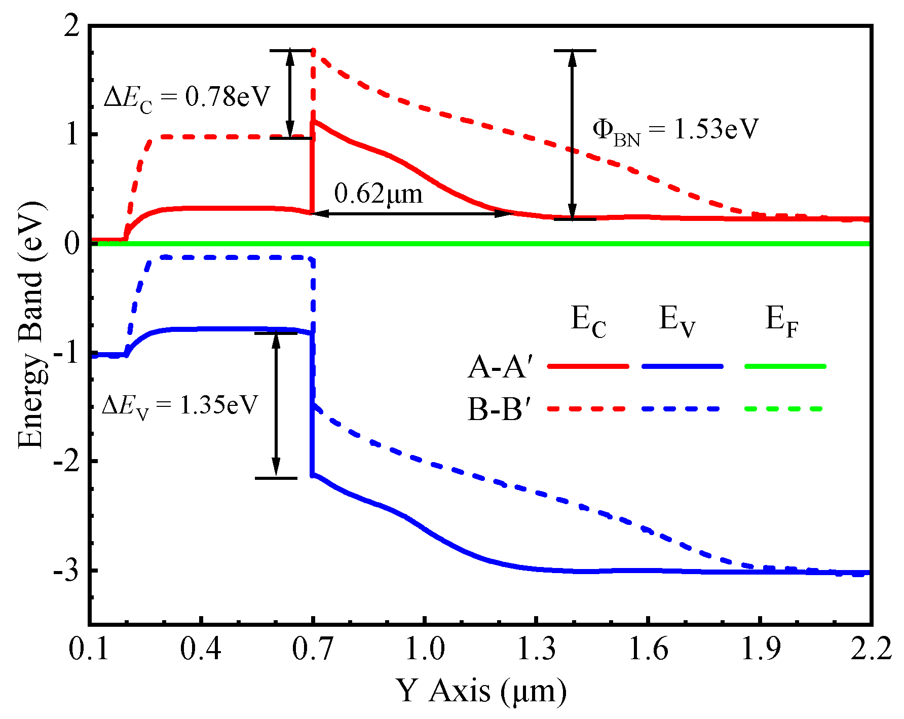
The energy band diagram of the Si/SiC heterojunction under thermal equilibrium along the paths [A–A′ and B–B′ lines in Figure 1b] is shown in Figure 2. The heterojunction has a conduction band barrier gap (∆EC) of 0.78 eV and a valence band barrier energy gap (∆EV) of 1.35 eV. This high electron barrier height (ΦBN) of approximately 1.53 eV results in a low Von for the HJD. It is also noteworthy that at Vgs = 0 V, the high-k dielectric induces an accumulation of electrons at the gate oxide interface, effectively creating an inversion layer. This phenomenon transforms the heterojunction near the gate oxide from a p–N type (comprising p-type narrow-gap and N-type wide-gap semiconductors) into an n–N type (comprising n-type narrow-gap and N-type wide-gap semiconductors).
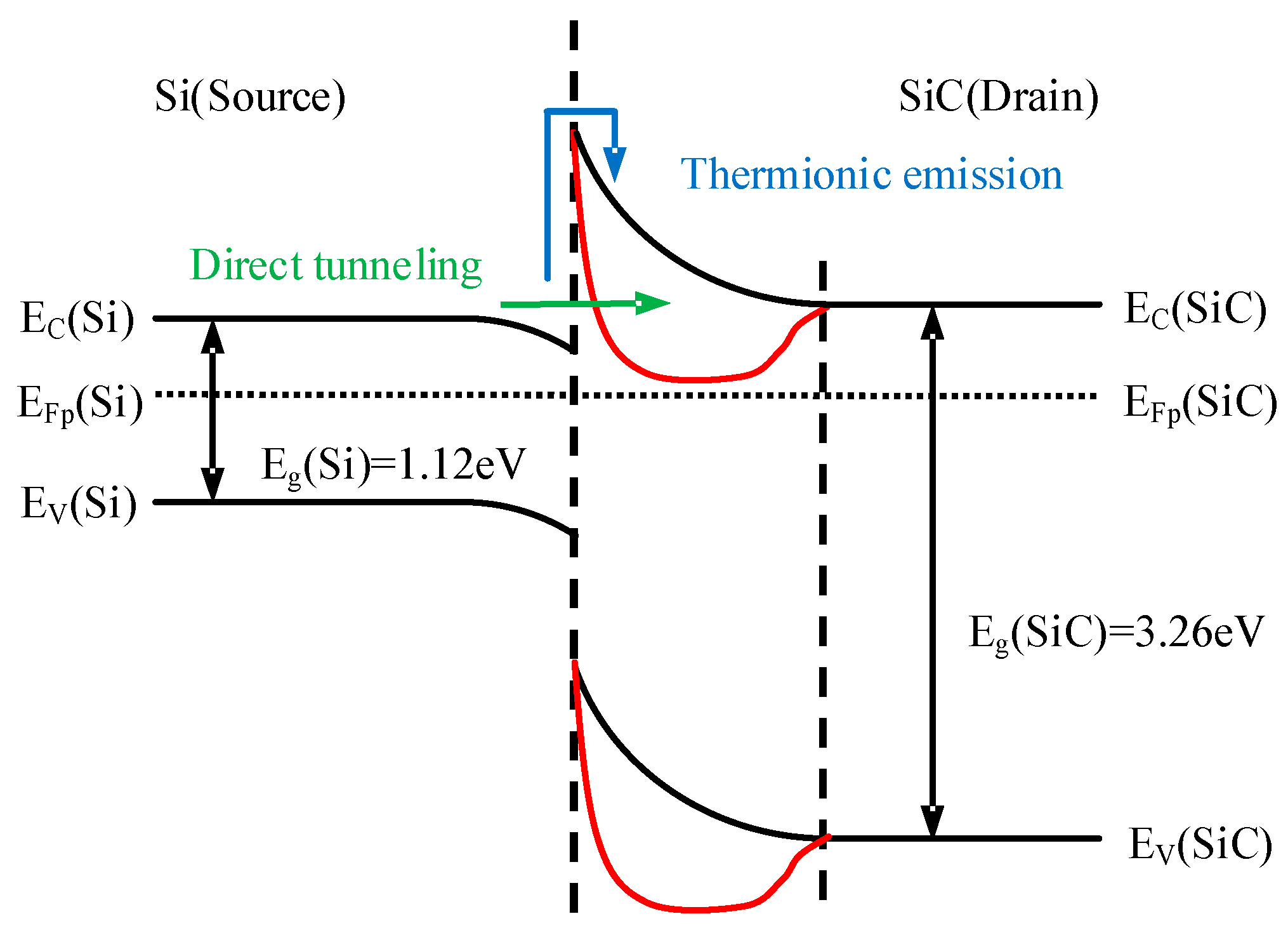
Figure 3 (black line) shows the energy band diagram at the n–Si/n–SiC heterojunction interface. Two distinct electron transport mechanisms exist at this interface: thermionic emission and direct tunneling, represented schematically by the blue and green paths in Figure 3, respectively. Under zero external bias, electron transport from the Si to the SiC side is governed by thermionic emission. In this regime, electrons must possess sufficient kinetic energy to overcome the heterojunction barrier, resulting in only a small fraction of the electron population being able to surmount the HJD barrier. However, as the barrier width narrows (as shown by the red curve in Figure 3), a finite probability for direct tunneling emerges. The tunneling probability is critically dependent on the distance the electron must tunnel through; a shorter distance yields an exponentially higher probability. When the barrier width is reduced to a sufficiently small value, the tunnel current increases dramatically, causing direct tunneling to become the dominant transport mechanism. This transition enables a substantially higher overall current.
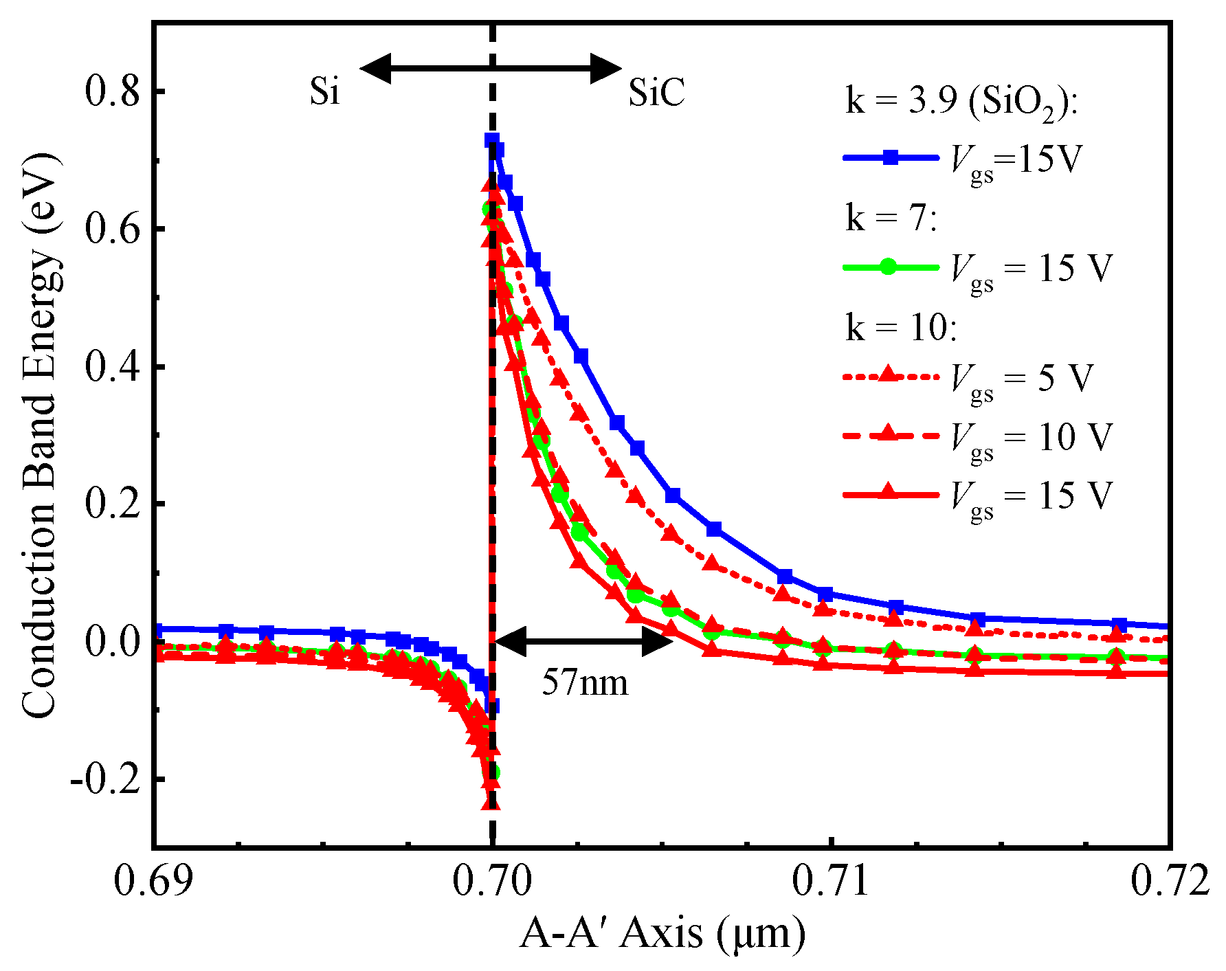
Figure 4 shows the conduction band energy along the A–A’ cutline [in Figure 1b] under varying k-values and Vgs. At Vgs = Vds = 0 V, the 0.62 μm depletion layer (in Figure 2) sustains drain voltage by blocking electron flow from Si P-ch to SiC CSL, enabled by heterojunction and P-well/CSL junction effects. Within effective tunneling distance, electrons tunnel through the heterojunction barrier into the SiC conduction band. Increasing Vgs enhances electron accumulation near the gate trench, thinning the heterojunction barrier. This enhanced accumulation reduces the width of the heterojunction barrier, thereby facilitating electron tunneling. At Vgs = 15 V and k = 10, the barrier thickness decreases to 57 nm, enabling efficient electron tunneling from silicon to SiC and forming a forward tunneling current.
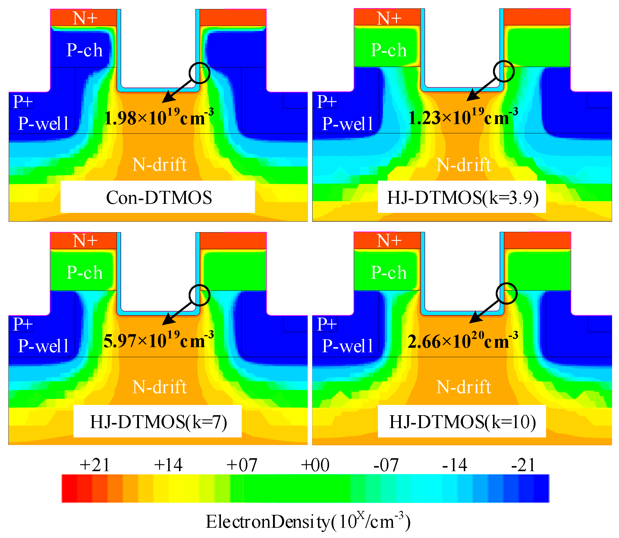
Figure 5 compares the electron density distribution of Con-DTMOS and HJ-DTMOS (k = 3.9, 7, 10) at Vgs = 15 V and Vds = 5 V. The heterojunction in HJ-DTMOS (k = 3.9) reduces electron density from 1.98 × 1019 cm−3 to 1.23 × 1019 cm−3 compared to Con-DTMOS due to depletion effects. High-k dielectrics enhance lateral electric fields, promoting electron accumulation at the semiconductor–dielectric interface. This accumulation intensifies with increasing k, peaking at 2.66 × 1020 cm−3 for k = 10, approximately ten times that of the Con-DTMOS. It is also noteworthy that, due to the spatially limited influence of k and Vgs, the width of the electron tunneling region is constrained. As a result, the HJ-DTMOS exhibits a higher electron density in the P-ch region compared to the Con-DTMOS, since electrons that fail to tunnel successfully accumulate within the P-ch region.
HJ-DTMOS employs a high-k dielectric to generate a dynamically tunable electron accumulation layer. This approach enables real-time modulation of the barrier width through gate bias, facilitating a balance between on-state conduction and off-state blocking capabilities. Consequently, it offers design flexibility compared to static doping-based methods [13].
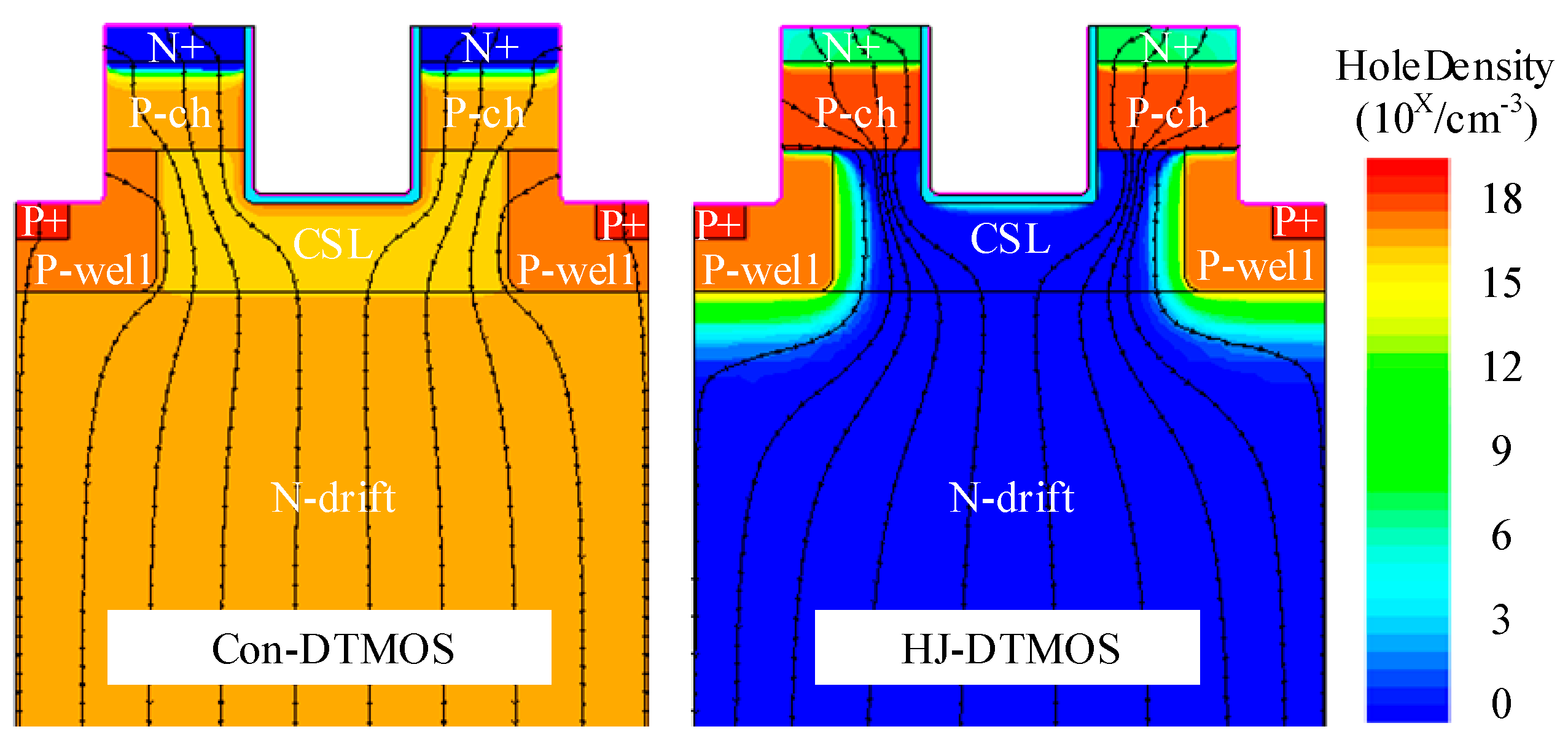
Figure 6 compares the hole density and total current flowline distribution for Con-DTMOS and HJ-DTMOS at Ids = −100 A/cm2. The Con-DTMOS operates in bipolar conduction mode, where current flows primarily through the parasitic PiN diode. In contrast, the HJ-DTMOS exhibits significantly reduced hole density within the N-drift region. This suppression of hole transport arises from the large valence band offset at the HJD, which impedes hole movement toward the drain while permitting electron current flow toward the source. Consequently, the markedly lower hole density in the HJ-DTMOS drift region confirms its unipolar conduction mechanism, which is similar to that of SBDs and distinct from the bipolar operation observed in Con-DTMOS.

3. Simulation Results and Discussion

The electrical characteristics of the HJ-DTMOS are compared with those of Con-DTMOS. The comparison includes Ron,sp, Vth, Von, and BV. The effects of the high-k dielectric and interface charge density are also analyzed.
As shown in Figure 7a, the Con-DTMOS exhibits high Von due to dominant conduction through its SiC PiN body diode. Conversely, HJ-DTMOS uses unipolar electron transport through its low ΦBN HJD, reducing Von to 1.53 V from 2.74 V at Isd = 20 A/cm2. Figure 7b presents transfer characteristics of Con-DTMOS versus HJ-DTMOS with varying k-values. The transfer characteristics reveal that a higher k-value significantly improves gate control. The HJ-DTMOS with k = 3.9 shows a higher Vth and poorer gate control than the Con-DTMOS due to inadequate barrier thinning. In contrast, the k = 10 device exhibits a markedly left-shifted curve, demonstrating enhanced gate modulation that reduces Vth substantially from 10.8 V to 5.8 V.
Figure 7c compares conduction I-V characteristics of Con-DTMOS and HJ-DTMOS with varying k-values. At low Vgs, HJ-DTMOS with small k exhibits nonlinear Ids-Vds behavior due to insufficient electron accumulation for heterojunction barrier thinning, preventing direct tunneling. Higher k-values compensate for this limitation through enhanced electron accumulation. At Vgs = 15 V, HJ-DTMOS displays ideal resistive IV curves, similar to the Con-DTMOS. Specifically, at Vgs = 15 V, HJ-DTMOS (k = 10) achieves a 20.5% lower Ron,sp of 1.78 mΩ·cm2 compared to the 2.24 mΩ·cm2 of Con-DTMOS. This reduction is attributed to the significantly lower resistance of the Si channel compared to that of the SiC channel. Although the heterojunction introduces additional heterointerface resistance [38], the combined resistance of the heterojunction and the Si channel under gate bias remains lower than that of the conventional SiC channel.
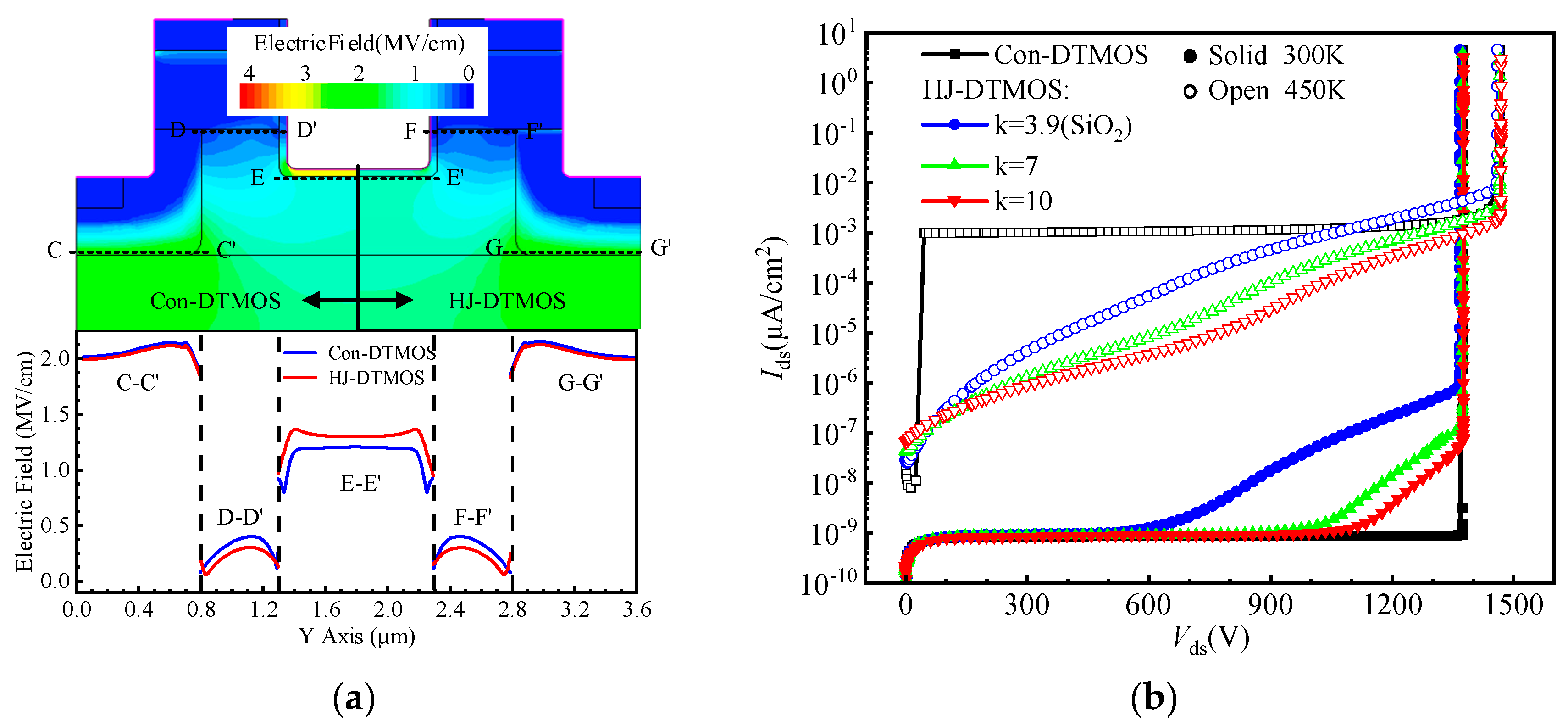
Figure 8a illustrates the electric field distribution of Con-DTMOS and HJ-DTMOS at Vds = 1200 V. By redistributing the electric field, the high-k dielectric reduces the field across the gate oxide and augments it in the underlying 4H-SiC. This augmented field, whose magnitude correlates positively with the k-value, intensifies the JFET effect between the 4H-SiC region and the adjacent P-well, consequently alleviating the field at the heterojunction interface. Therefore, a higher k-value accordingly results in a stronger suppression of the electric field at the heterojunction interface.
Figure 8b shows the blocking characteristics of the Con-DTMOS and the HJ-DTMOS at room temperature and high temperature. At room temperature, both the Con-DTMOS and HJ-DTMOS exhibit highly similar electric field distributions, with the peak field located at the P-well corner, as revealed in Figure 8a. This similarity enables both devices to maintain a comparable avalanche breakdown voltage of approximately 1380 V. However, differences in the bulk and surface electric fields lead to distinct leakage currents. Owing to its heterojunction properties, the HJ-DTMOS exhibits a leakage current that is orders of magnitude higher than that of the Con-DTMOS at high voltages. Notably, a higher k-value effectively suppresses the electric field at the heterojunction interface, which consequently reduces the leakage current. At elevated temperatures, however, thermionic emission becomes the dominant leakage mechanism across the heterojunction, strongly dependent on barrier height and temperature. Consequently, the leakage current of HJ-DTMOS increases with rising temperature. Rising temperature increases the breakdown voltage of HJ-DTMOS primarily due to enhanced lattice scattering, which impedes carrier acceleration and necessitates a higher voltage to initiate avalanche multiplication.
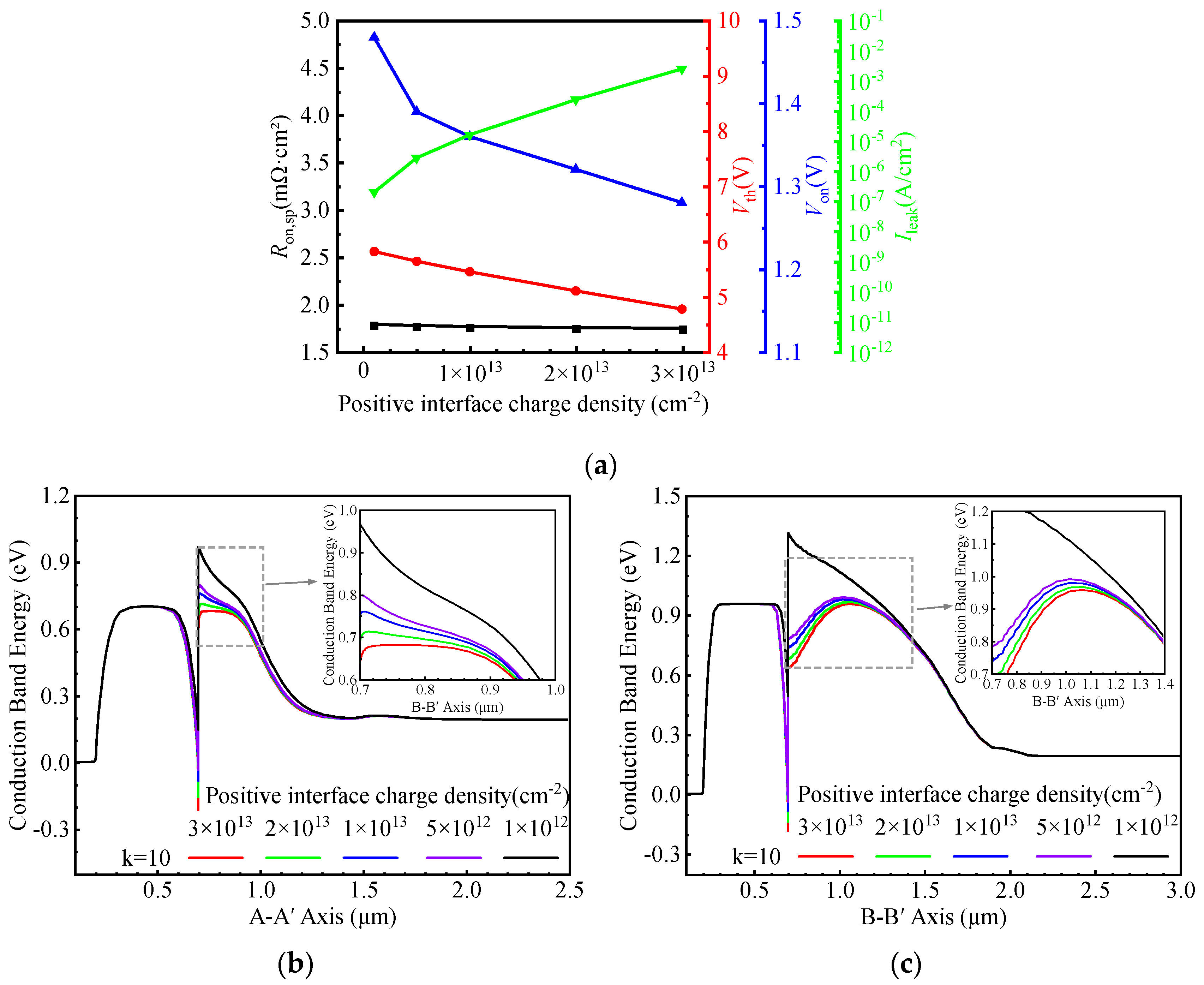
Figure 9a illustrates the influence of positive interface charge density on the electrical characteristics of the HJ-DTMOS. The band modulation at the Si/SiC interface is driven by an internal electric field induced by interface charges, and its intensity increases with the charge density.
Figure 9b presents the equilibrium energy band diagrams along the A–A′ cutline under various positive interface charge densities. A higher density of positive interface charges leads to more significant downward band bending at the interface, facilitating the formation of an electron accumulation layer. Under forward conduction, the heterojunction barrier width is reduced, promoting electron tunneling and improving carrier transport. As a result, both Ron,sp, and Vth decrease with elevated positive charge density.
Figure 9c shows the corresponding band diagrams along the B–B′ cutline. As the positive charge density increases, the dominant factor determining ΦBN shifts from the heterointerface toward the SiC bulk, leading to a gradual reduction in Von. The BV remains largely unaffected by variations in interface charge density, owing to the shielding effect of the dual P-well structure. However, at 1200 V, the leakage current (Ileak) increases sharply with higher positive charge density, resulting in long-term reliability degradation. Therefore, to ensure stable device operation, the positive interface charge density should be minimized.
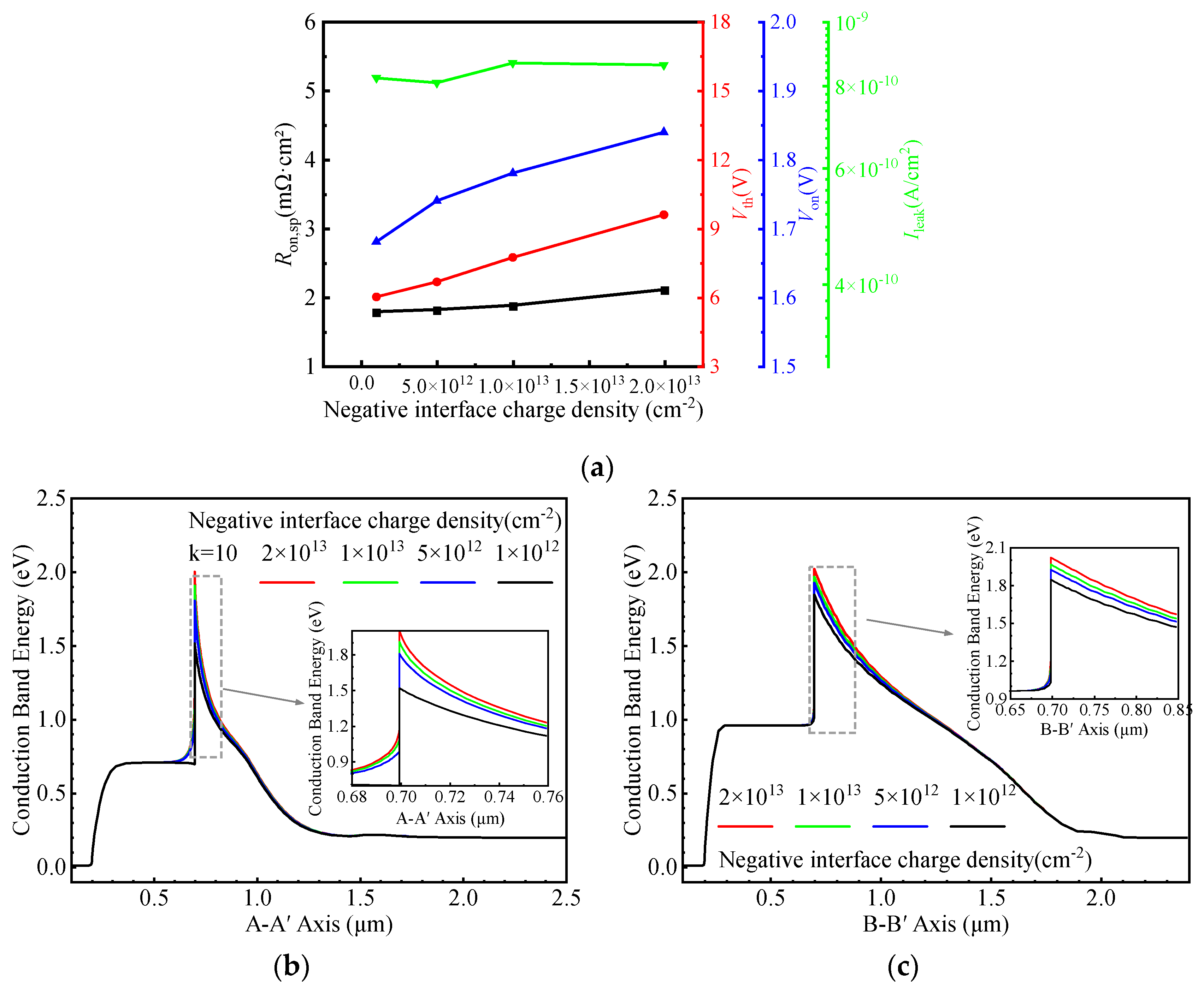
Figure 10a illustrates the influence of negative interface charge density on the electrical characteristics of the HJ-DTMOS. Figure 10b presents the equilibrium energy band diagrams along the A–A′ cutline under various negative charge densities. In contrast to positive interface charge, negative interface charges cause significant upward band bending at the interface, thereby reducing the local electron concentration. Under forward conduction conditions, the heterojunction barrier width increases, which hinders electron tunneling. Consequently, both Ron,sp, and Vth increase with rising negative charge density. Figure 10c shows the corresponding energy band diagrams along the B–B’ cutline. As the negative charge density increases, the ΦBN continually rises, leading to a gradual increase in Von. Although the Ileak exhibits some fluctuation with increasing negative charge density at 1200 V, the BV remains largely unaffected. Therefore, to ensure satisfactory conduction performance of the device, the negative interface charge density should be minimized.
Figure 11 shows a possible process for the proposed HJ-DTMOS. First, the N-drift region is formed by epitaxial growth on the N+ substrate, as shown in Figure 11a. Then, the CSL region is formed by epitaxial growth. A high-quality Si/SiC heterostructure is subsequently realized using surface activation bonding (SAB), accompanied by a controlled post-bonding annealing step, as shown in Figure 11b [23]. The P-ch and the N+ source regions are then fabricated through double implantation, depicted in Figure 11c. Thereafter, a gate trench is etched, and a high-k dielectric gate oxide is deposited via atomic layer deposition (ALD) [39]. The gate electrode is subsequently deposited and patterned, as presented in Figure 11d. A source trench is then formed, and the P-well and P+ regions are defined by tilted ion implantation along its sidewall, as shown in Figure 11e. Finally, a passivation layer is deposited, contact windows are etched, and ohmic contacts are established, completing the structure in Figure 11f.

4. Conclusions

This work proposed and thoroughly investigated, through TCAD simulations, a Si/SiC heterojunction double-trench MOSFET (HJ-DTMOS). The key feature of this structure is the strategic replacement of the conventional SiC N+ source and P-channel regions with silicon, forming a Si/SiC heterojunction. This design effectively addresses two fundamental limitations of standard SiC MOSFETs: low channel mobility and bipolar degradation of the body diode. Simulation results demonstrate significant performance improvements: the Von is reduced to 1.53 V (from 2.74 V in conventional devices), effectively suppressing bipolar degradation, while the Ron,sp is lowered by 20.5% to 1.78 mΩ·cm2 without compromising the breakdown voltage. These enhancements are attributed to the heterojunction’s Schottky-like behavior and the high-k dielectric-induced tunneling transport. While the trenched source and heavily doped P-well enhance reliability by mitigating electric field concentrations, the quality of the interface remains critical for achieving optimal performance. This work demonstrates the HJ-DTMOS’s strong potential for high-performance power applications, with experimental validation planned for future research.

Author Contributions

Conceptualization, investigation, and simulation, Y.K.; data curation, T.L.; writing—original draft preparation, Y.K. and Z.Q.; writing—review and editing, S.L. and X.H.; supervision, D.L. and X.H. All authors have read and agreed to the published version of the manuscript.

Funding

This research was funded by National Natural Science Foundation of China (No. U2469204).

Data Availability Statement

The original contributions presented in this study are included in the article. Further inquiries can be directed to the corresponding author.

Conflicts of Interest

The authors declare no conflicts of interest.

Abbreviations

The following abbreviations are used in this manuscript:
HJ-DTMOSSi/SiC heterojunction double-trench MOSFET
Con-DTMOSConventional double-trench MOSFET
HJDHeterojunction diode
SBDSchottky barrier diode
JBSJunction barrier Schottky diode
MPSMerged PiN/Schottky diode
MCDMOS-channel diode
DioMOSDiode-integrated MOSFET
CSLCurrent spreading layer
SABSurface activation bonding
ALDAtomic layer deposition
SRHShockley–Read–Hall recombination
ΔEcConduction-band offset at Si/SiC heterojunction
ΔEvValence-band offset at Si/SiC heterojunction
ΦBNElectron barrier height of heterojunction
kRelative permittivity of gate dielectric
Ron,spSpecific on-resistance
BVBreakdown voltage
VonTurn-on voltage
VdsDrain-to-source voltage
IdsDrain-to-source current
IsdSource-to-drain current
VgsGate-to-source voltage
VthThreshold voltage
IleakLeakage current
A–A′, B–B′Cut-line labels in figures
C–C′, D–D′, E–E′, F–F′, G–G′Electric-field profile cut-lines

References

  1. She, X.; Huang, A.Q.; Lucía, O.; Ozpineci, B. Review of Silicon Carbide Power Devices and Their Applications. IEEE Trans. Ind. Electron. 2017, 64, 8193–8205. [Google Scholar] [CrossRef]
  2. Spaziani, L.; Lu, L. Silicon, GaN and SiC: There’s room for all: An application space overview of device considerations. In Proceedings of the 2018 IEEE 30th International Symposium on Power Semiconductor Devices and ICs (ISPSD), Chicago, IL, USA, 13–17 May 2018; pp. 8–11. [Google Scholar] [CrossRef]
  3. Millán, J.; Godignon, P.; Perpiñà, X.; Pérez-Tomás, A.; Rebollo, J. A Survey of Wide Bandgap Power Semiconductor Devices. IEEE Trans. Power Electron. 2014, 29, 2155–2163. [Google Scholar] [CrossRef]
  4. Karki, U.; González-Santini, N.S.; Peng, F.Z. Effect of Gate-Oxide Degradation on Electrical Parameters of Silicon Carbide MOSFETs. IEEE Trans. Electron Devices 2020, 67, 2544–2552. [Google Scholar] [CrossRef]
  5. Tachiki, K.; Kimoto, T. Improvement of Both n- and p-Channel Mobilities in 4H-SiC MOSFETs by High-Temperature N2 Annealing. IEEE Trans. Electron Devices 2021, 68, 638–644. [Google Scholar] [CrossRef]
  6. Zhang, Y.; Yuan, H.; Guo, J.; Yang, H.; Zhou, Y.; Du, F.; Liu, Y.; Liu, K.; Han, C.; Song, Q.; et al. Long-Term Lifetime Evolution Mechanism of 4H-SiC MOSFETs Under Nitric Oxide Annealing. IEEE Trans. Electron Devices 2024, 71, 7682–7688. [Google Scholar] [CrossRef]
  7. Sharmila, P.; Supraja, G.; Haripriya, D.; Sivamani, C.; Narayana, A.L. Silicon carbide MOSFETs: A critical review of applications, technological advancements, and future perspectives. Micro Nanostruct. 2025, 202, 208126. [Google Scholar] [CrossRef]
  8. Fiorenza, P.; Giannazzo, F.; Roccaforte, F. Characterization of SiO2/4H-SiC Interfaces in 4H-SiC MOSFETs: A Review. Energies 2019, 12, 2310. [Google Scholar] [CrossRef]
  9. Modic, A.; Liu, G.; Ahyi, A.C.; Zhou, Y.; Xu, P.; Hamilton, M.C.; Williams, J.R.; Feldman, L.C.; Dhar, S. High channel mobility 4H-SiC MOSFETs by antimony counter-doping. IEEE Electron Device Lett. 2014, 35, 894–896. [Google Scholar] [CrossRef]
  10. Okamoto, D.; Sometani, M.; Harada, S.; Kosugi, R.; Yonezawa, Y.; Yano, H. Improved Channel Mobility in 4H-SiC MOSFETs by Boron Passivation. IEEE Electron Device Lett. 2014, 35, 1176–1178. [Google Scholar] [CrossRef]
  11. Chen, L.; Guy, O.J.; Jennings, M.R.; Igic, P.; Wilks, S.P.; Mawby, P.A. Study of a novel Si/SiC hetero-junction MOSFET. Solid-State Electron. 2007, 51, 662–666. [Google Scholar] [CrossRef]
  12. Duan, B.; Yang, X.; Lv, J.; Yang, Y. Novel SiC/Si Heterojunction Power MOSFET With Breakdown Point Transfer Terminal Technology by TCAD Simulation Study. IEEE Trans. Electron Devices 2018, 65, 3388–3393. [Google Scholar] [CrossRef]
  13. Chen, H.; Zhang, Y.; Zhou, R.; Wang, Z.; Lu, C.; Li, Z.; Zhang, B. A Novel Low On–State Resistance Si/4H–SiC Heterojunction VDMOS with Electron Tunneling Layer Based on a Discussion of the Hetero–Transfer Mechanism. Crystals 2023, 13, 778. [Google Scholar] [CrossRef]
  14. Wang, N.; Hu, X.; Xu, Y.; Li, T. A Triple RESURF Si/SiC HeteroJunction LDMOS and Its Analytical Model. Int. J. Numer. Model. Electron. Netw. Devices Fields 2025, 38, e70039. [Google Scholar] [CrossRef]
  15. Park, S.; Mun, S.; Kim, K.H.; Yang, M.; Chun, Y.T.; Yi, S.N.; Ahn, H.S.; Lee, J.H.; Jang, Y.-S.; Lee, W.J.; et al. Growth of hexagonal-shape Si on a 4H–SiC substrate by mixed-source hydride vapor phase epitaxy. J. Korean Phys. Soc. 2024, 84, 198–207. [Google Scholar] [CrossRef]
  16. Chan, C.W.; Li, F.; Sanchez, A.; Mawby, P.A.; Gammon, P.M. Comparative Study of RESURF Si/SiC LDMOSFETs for High-Temperature Applications Using TCAD Modeling. IEEE Trans. Electron Devices 2017, 64, 3713–3718. [Google Scholar] [CrossRef]
  17. Zhang, W.; Zhang, C.; Wu, J.; Yang, F.; An, Y.; Hu, F.; Fan, J. Low temperature hydrophilic SiC wafer level direct bonding for ultrahigh-voltage device applications. Micromachines 2021, 12, 1575. [Google Scholar] [CrossRef] [PubMed]
  18. Lei, F.; Lu, W.; Liu, F.; Li, B.; Wang, J.; Li, J. Investigation on Wafer Heterogeneous Bonding Process and Performance of CMOS Integrated Circuit on Silicon Carbide Substrate. In Proceedings of the 2024 25th International Conference on Electronic Packaging Technology (ICEPT), Tianjin, China, 7–9 August 2024; pp. 1–5. [Google Scholar] [CrossRef]
  19. Shigekawa, N.; Liang, J.; Ohno, Y. Heterojunctions fabricated by surface activated bonding–dependence of their nanostructural and electrical characteristics on thermal process. Jpn. J. Appl. Phys. 2022, 61, 120101. [Google Scholar] [CrossRef]
  20. Liang, J.; Shimizu, S.; Nishida, S.; Shigekawa, N.; Arai, M. 4H-SiC/Si Heterojunction Bipolar Transistors Fabricated by Surface Activated Bonding. ECS Solid State Lett. 2015, 4, Q55. [Google Scholar] [CrossRef]
  21. Gammon, P.M.; Chan, C.W.; Li, F.; Gity, F.; Trajkovic, T.; Pathirana, V.; Flandre, D.; Kilchytska, V. Development, characterisation and simulation of wafer bonded Si-on-SiC substrates. Mater. Sci. Semicond. Process 2018, 78, 69–74. [Google Scholar] [CrossRef]
  22. Guo, R.; Xu, B.; Mu, F.; Shiomi, J. Enhancing and mapping thermal boundary conductance across bonded Si-SiC interface. Appl. Surf. Sci. 2025, 682, 161724. [Google Scholar] [CrossRef]
  23. Huang, S.; Liu, F.; Liu, J.; Mao, R.; Zhang, J.; Liu, Z.; Sun, F.; Wang, Z.; Gao, P. Direct Bonding of 6-in. SiC/Si Wafer with Enhanced Thermal Interface. ACS Appl. Mater. Interfaces 2025, 17, 46409–46416. [Google Scholar] [CrossRef]
  24. Long, Y.T.; Chen, Y.; Wang, P.K.; Hou, B.; He, H. A Novel Insight Into the Mechanism of Bipolar Degradation in 4H-SiC MOSFET. IEEE Electron Device Lett. 2025, 46, 464–467. [Google Scholar] [CrossRef]
  25. Palanisamy, S.; Basler, T.; Lutz, J.; Künzel, C.; Wehrhahn-Kilian, L.; Elpelt, R. Investigation of the bipolar degradation of SiC MOSFET body diodes and the influence of current density. In Proceedings of the 2021 IEEE International Reliability Physics Symposium (IRPS), Monterey, CA, USA, 21–25 March 2021; pp. 1–6. [Google Scholar] [CrossRef]
  26. Sung, W.; Baliga, B.J. Monolithically Integrated 4H-SiC MOSFET and JBS Diode (JBSFET) Using a Single Ohmic/Schottky Process Scheme. IEEE Electron Device Lett. 2016, 37, 1605–1608. [Google Scholar] [CrossRef]
  27. Todaka, S.; Matsui, K.; Aiba, R.; Yano, H.; Iwamuro, N.; Baba, M.; Harada, S. Experimental and Numerical Demonstration of Superior RBSOAs in 1.2 kV SiC Trench and SBD-integrated Trench MOSFETs. In Proceedings of the 2021 33rd International Symposium on Power Semiconductor Devices and ICs (ISPSD), Nagoya, Japan, 30 May–3 June 2021; pp. 219–222. [Google Scholar] [CrossRef]
  28. Yu, Y.R.; Liu, T.; Ma, R.Y.; Cheng, Z.J.; Tao, J.Y.; Guo, J.W.; Wu, H.; Hu, S.D. A Novel Asymmetric Trench SiC MOSFET With an Integrated JFET for Improved Reverse Conduction Performance. IEEE Trans. Electron Devices 2024, 71, 1546–1552. [Google Scholar] [CrossRef]
  29. Sundaresan, S.; Park, J.; Mulpuri, V.; Singh, R. Performance and Robustness of 6500 V SiC DMOSFETs with Integrated MPS diodes. In Proceedings of the 2021 33rd International Symposium on Power Semiconductor Devices and ICs (ISPSD), Nagoya, Japan, 30 May–3 June 2021; pp. 235–238. [Google Scholar] [CrossRef]
  30. Uchida, M.; Horikawa, N.; Tanaka, K.; Takahashi, K.; Kiyosawa, T.; Hayashi, M.; Niwayama, M.; Kusumoto, O.; Adachi, K.; Kudou, C.; et al. Novel SiC power MOSFET with integrated unipolar internal inverse MOS-channel diode. In Proceedings of the 2011 International Electron Devices Meeting, Washington, DC, USA, 5–7 December 2011; pp. 26.6.1–26.6.4. [Google Scholar] [CrossRef]
  31. Zhou, X.; Gong, H.; Jia, Y.; Hu, D.; Wu, Y.; Xia, T.; Pang, H.; Zhao, Y. SiC Planar MOSFETs With Built-In Reverse MOS-Channel Diode for Enhanced Performance. IEEE J. Electron Devices Soc. 2020, 8, 619–625. [Google Scholar] [CrossRef]
  32. Deng, X.; Xu, X.; Li, X.; Li, X.; Wen, Y.; Chen, W. A Novel SiC MOSFET Embedding Low Barrier Diode With Enhanced Third Quadrant and Switching Performance. IEEE Electron Device Lett. 2020, 41, 1472–1475. [Google Scholar] [CrossRef]
  33. Liang, S.; Yu, H.; Liu, H.; Wang, Y.; Wang, J. A novel SiC power MOSFET with integrated polySi/SiC heterojunction freewheeling diode. Semicond. Sci. Technol. 2021, 36, 095017. [Google Scholar] [CrossRef]
  34. Yu, H.; Liang, S.; Liu, H.; Wang, J.; Shen, Z.J. Numerical Study of SiC MOSFET With Integrated n-/n-Type Poly-Si/SiC Heterojunction Freewheeling Diode. IEEE Trans. Electron Devices 2021, 68, 4571–4576. [Google Scholar] [CrossRef]
  35. Robertson, J.; Wallace, R.M. High-K materials and metal gates for CMOS applications. Mater. Sci. Eng. R Rep. 2015, 88, 1–41. [Google Scholar] [CrossRef]
  36. Wei, J.; Liu, S.; Tong, J.; Zhang, X.; Sun, W.; Huang, A.Q. Understanding Short-Circuit Failure Mechanism of Double-Trench SiC Power MOSFETs. IEEE Trans. Electron Devices 2020, 67, 5593–5599. [Google Scholar] [CrossRef]
  37. Lan, Z.; Ou, Y.; Hu, X.; Liu, D. A Novel 4H-SiC Asymmetric MOSFET with Step Trench. Micromachines 2024, 15, 724. [Google Scholar] [CrossRef] [PubMed]
  38. Yoon, J.; Kim, K. High-performance SiC MOSFET embedded heterojunction diode with electric field protection region. Semicond. Sci. Technol. 2022, 37, 015014. [Google Scholar] [CrossRef]
  39. Jung, E.S.; Yoo, J.; Choi, T.M.; Lee, H.R.; Lee, C.Y.; Kim, D.H.; Pyo, S.G. Performance variation with pristine and doped high-k materials via atomic layer deposition. Int. J. Appl. Ceram. Technol. 2025, 22, e15001. [Google Scholar] [CrossRef]
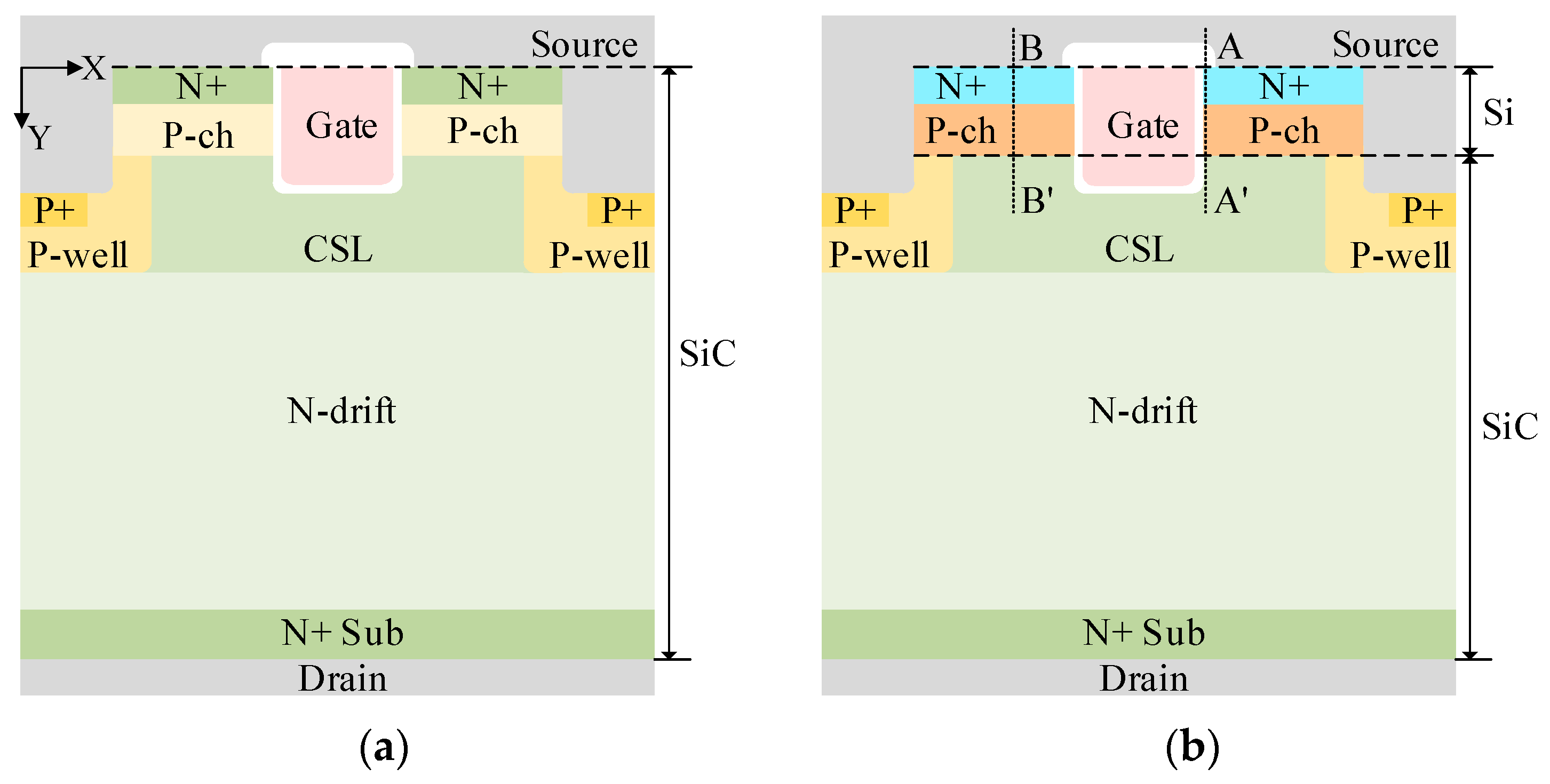
Figure 1. Schematic cross-section of (a) Con-DTMOS and (b) HJ-DTMOS.
Micromachines 16 01335 g001
Figure 2. Energy band diagram at thermal equilibrium along A–A′ and B–B′ cut-lines.
Micromachines 16 01335 g002
Figure 3. Energy band diagram of the n–Si/n–SiC heterojunction.
Micromachines 16 01335 g003
Figure 4. Conduction band energy along the tunneling path at different k-values and Vgs.
Micromachines 16 01335 g004
Figure 5. Electron density distribution of Con-DTMOS and HJ-DTMOS (k = 3.9, 7, 10) at Vgs = 15 V and Vds = 5 V.
Micromachines 16 01335 g005
Figure 6. Hole density and total current flowlines distribution for Con-DTMOS and HJ-DTMOS (k = 10) at Ids = −100 A/cm2.
Micromachines 16 01335 g006
Figure 7. (a) Reverse conduction I–V characteristics of the Con-DTMOS and HJ-DTMOS under Vgs = –5 V. (b) Transfer characteristics and (c) output I–V characteristics of the Con-DTMOS and HJ-DTMOS at various k-values.
Micromachines 16 01335 g007
Figure 8. (a) Distribution of electric field along the P-well/N-drift junctions (C–C′ and G–G′), the heterojunctions (D–D′ and F–F′), and the trench bottom (E–E′) of Con-DTMOS and HJ-DTMOS (k = 10) at Vds = 1200 V. (b) Blocking characteristics of the Con-DTMOS and the HJ-DTMOS.
Micromachines 16 01335 g008
Figure 9. (a) Dependence of Ron,sp, Vth, Von, and Ileak on the positive interface charge density. Energy band diagrams at thermal equilibrium along the (b) A–A′ and (c) B–B′ cut-lines for different positive interface charge densities.
Micromachines 16 01335 g009
Figure 10. (a) Dependence of Ron,sp, Vth, Von, and Ileak on the negative interface charge density. Energy band diagrams at thermal equilibrium along the (b) A–A′ and (c) B–B′ cut-lines for different negative interface charge densities.
Micromachines 16 01335 g010
Figure 11. Key fabrication process steps for the HJ-DTMOS: (a) Form the epitaxial N-drift layer and CSL on N+ substrate; (b) Form Si/SiC heterostructures by direct bonding; (c) Form the P-ch region and N+ source region by double implantation; (d) Etch the gate trench, deposit a high-k gate dielectric by ALD, and deposit polysilicon for the gate; (e) Etch source trench and ion implantation to form the P-well region and P+ region; and (f) Form the source and drain electrodes.
Micromachines 16 01335 g011
Table 1. Device parameters for simulations.
ParametersHJ-DTMOSCon-DTMOS
Cell pitch (μm)3.63.6
Si layer thickness(μm)0.7-
SiC layer thickness(μm)12.813.5
N-drift thickness (μm)1010
N-drift doping (cm−3)5 × 10155 × 1015
CSL thickness (μm)0.80.8
CSL doping (cm−3)1 × 10161 × 1016
P-ch thickness (μm)0.50.5
P-ch doping (cm−3)2 × 10172 × 1017
Trench depth (μm)11
Trench width (μm)11
Gate oxide thickness (nm)5050
Disclaimer/Publisher’s Note: The statements, opinions and data contained in all publications are solely those of the individual author(s) and contributor(s) and not of MDPI and/or the editor(s). MDPI and/or the editor(s) disclaim responsibility for any injury to people or property resulting from any ideas, methods, instructions or products referred to in the content.