An Enhanced Cooling Method for Power Modules on All-Electric Ships Based on Parameter Optimization and Special-Shaped Design of Sintered Heat Pipes
Abstract
1. Introduction
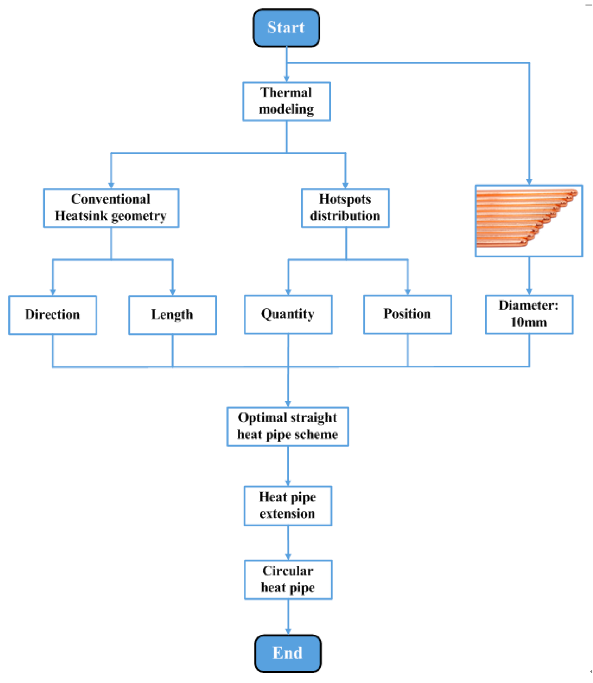
- To establish a theoretical framework and optimization procedure for the key physical parameters of sintered heat pipes;
- To propose and theoretically justify a novel, specially shaped heat pipe design;
- To formulate the findings into a convenient, generalized design methodology that can be applied to optimize heatsinks for various power electronic converters;
- To verify the proposed enhanced cooling method through a comprehensive case study involving both finite element simulations and experiments.
2. Research on Enhanced Cooling Methods
2.1. Problems of Traditional Heatsinks
2.2. Principle and Classification of Heat Pipes
2.3. Research on Parameter Optimization of Straight Heat Pipes
- (1)
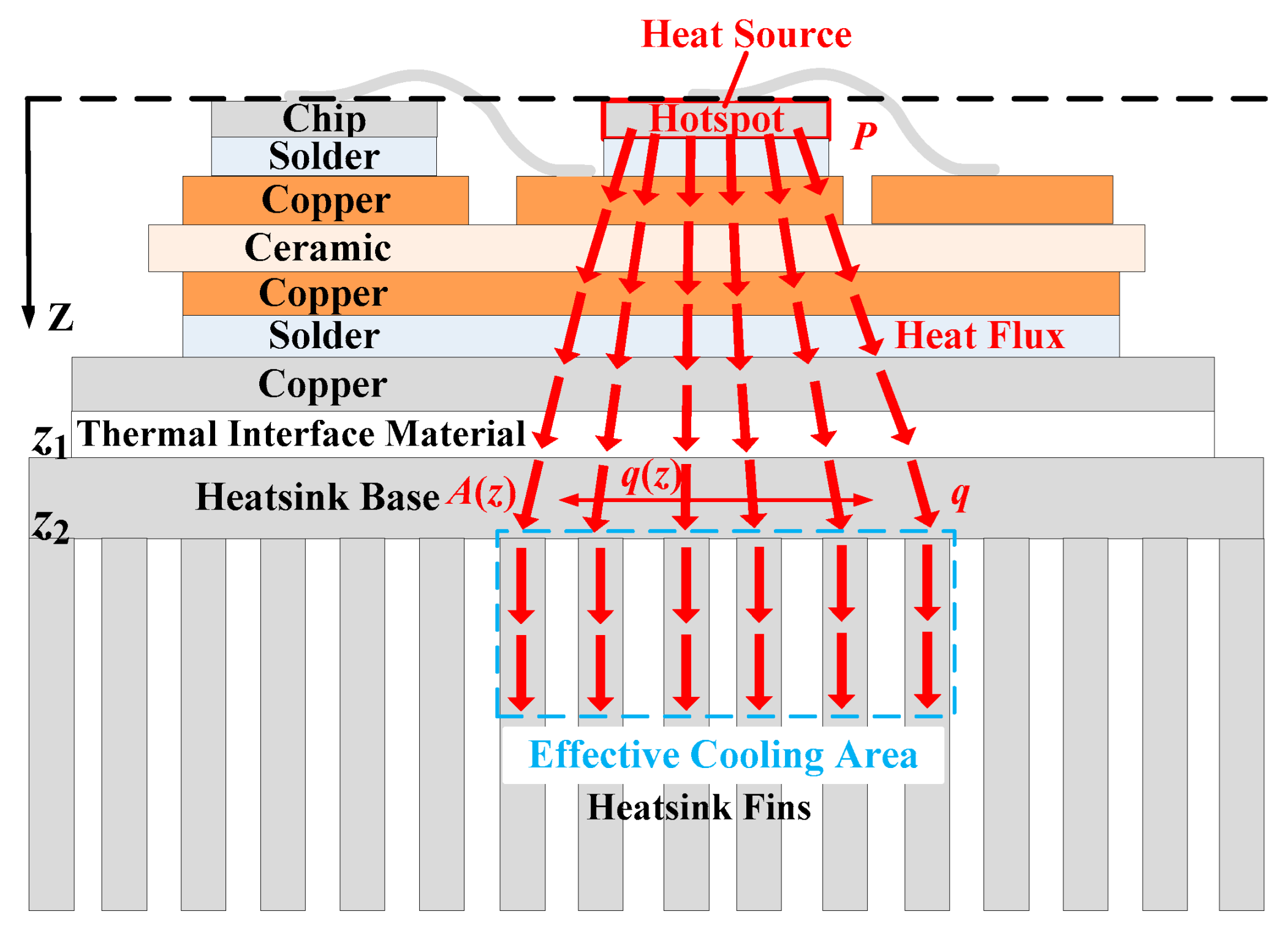
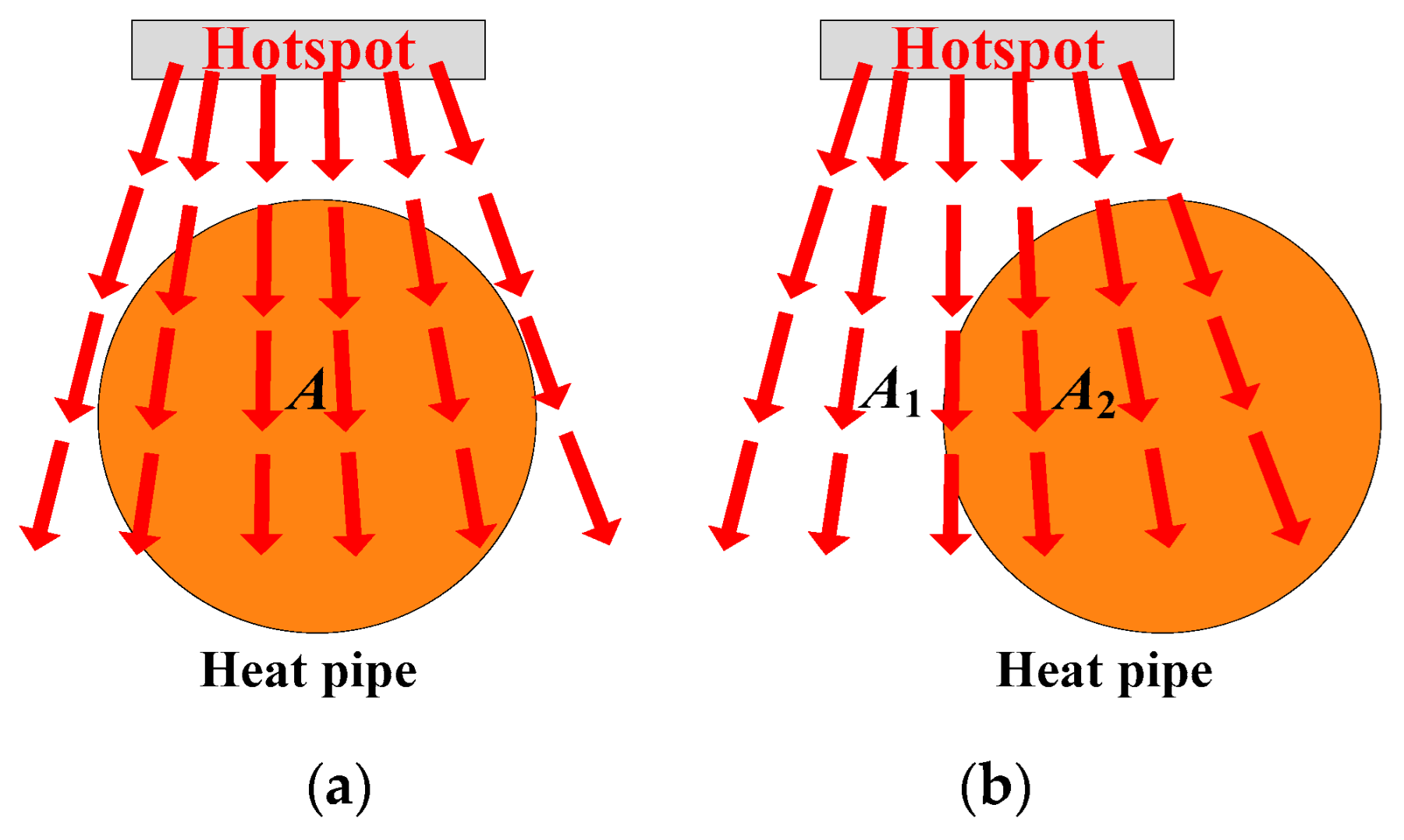
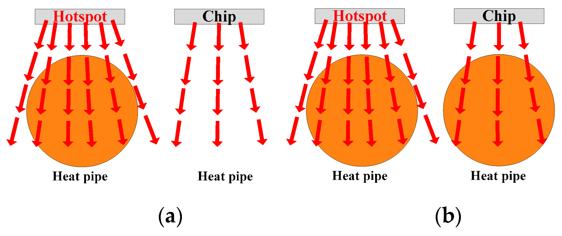
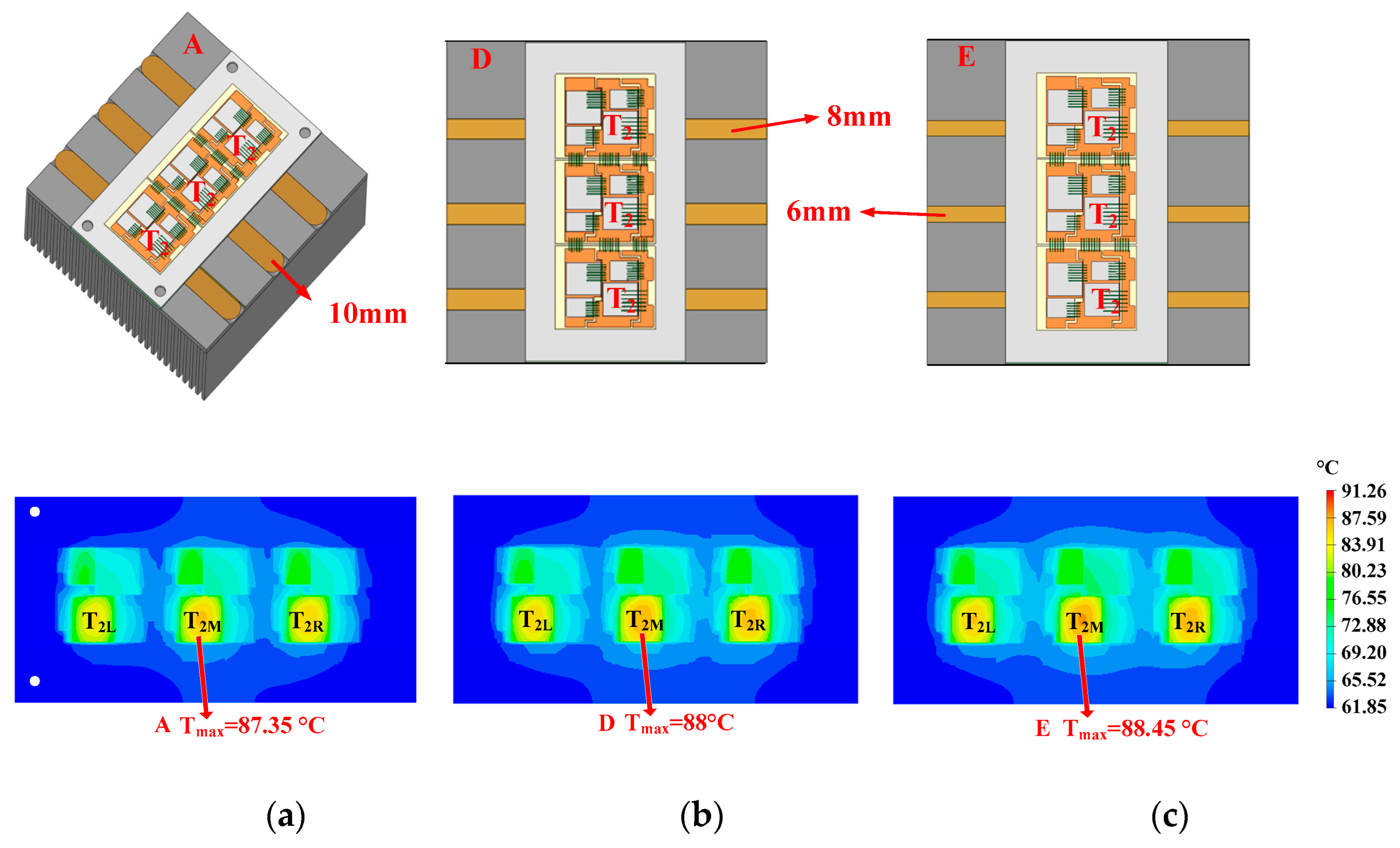
- Position: Position here refers to the relative horizontal position between the axis of the heat pipe and the axis of the hotspot chip. As shown in Figure 10, when the horizontal distance between the heat pipe’s axis and the hotspot chip axis is 0 (the heat pipe is arranged directly under the hotspot chip), the heat pipe can cover the thermal path from the hotspot chip to the heatsink base as extensively as possible. Hence, the heat pipe can absorb and spread the heat of the hotspot chip, reducing the heat flux as much as possible. As the two axes deviate, the heat pipe cannot fully cover the thermal path. Therefore, the effectiveness of heat pipes in absorbing and transmitting heat gradually weakens.
- (2)
- Diameter: As shown in Figure 11, a thicker heat pipe can cover the thermal path as extensively as possible. Similarly, the heat pipe can absorb and spread the heat of the hotspot chip, reducing the heat flux as much as possible. As the heat pipe gradually becomes thinner, the heat pipe cannot fully cover the thermal path. Thus, the effectiveness of heat pipes in absorbing and transmitting heat gradually weakens.
- (3)
- Quantity: As can be seen in Figure 12, a heat pipe that is directly under the hotspot chip and with maximum thickness can fully cover the thermal path. If some heat pipes are added, additional heat pipes will be located below normal chips with lower power losses. As additional heat pipes are not on the thermal path of the hotspot chip, they have little effect on reducing the heat flux of hotspot chips.
- (4)
- Length: As shown in Figure 13, a longer heat pipe can transfer heat further away, resulting in a larger effective thermal conduction area. And the heat flux of the heatsink base will be lower.
- (5)
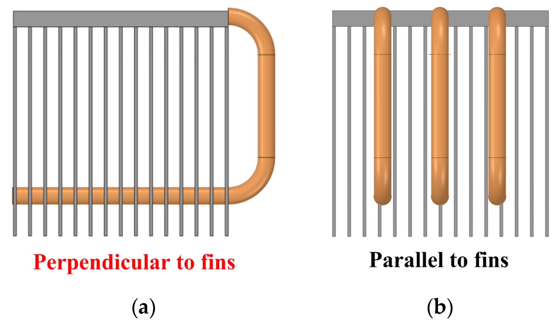
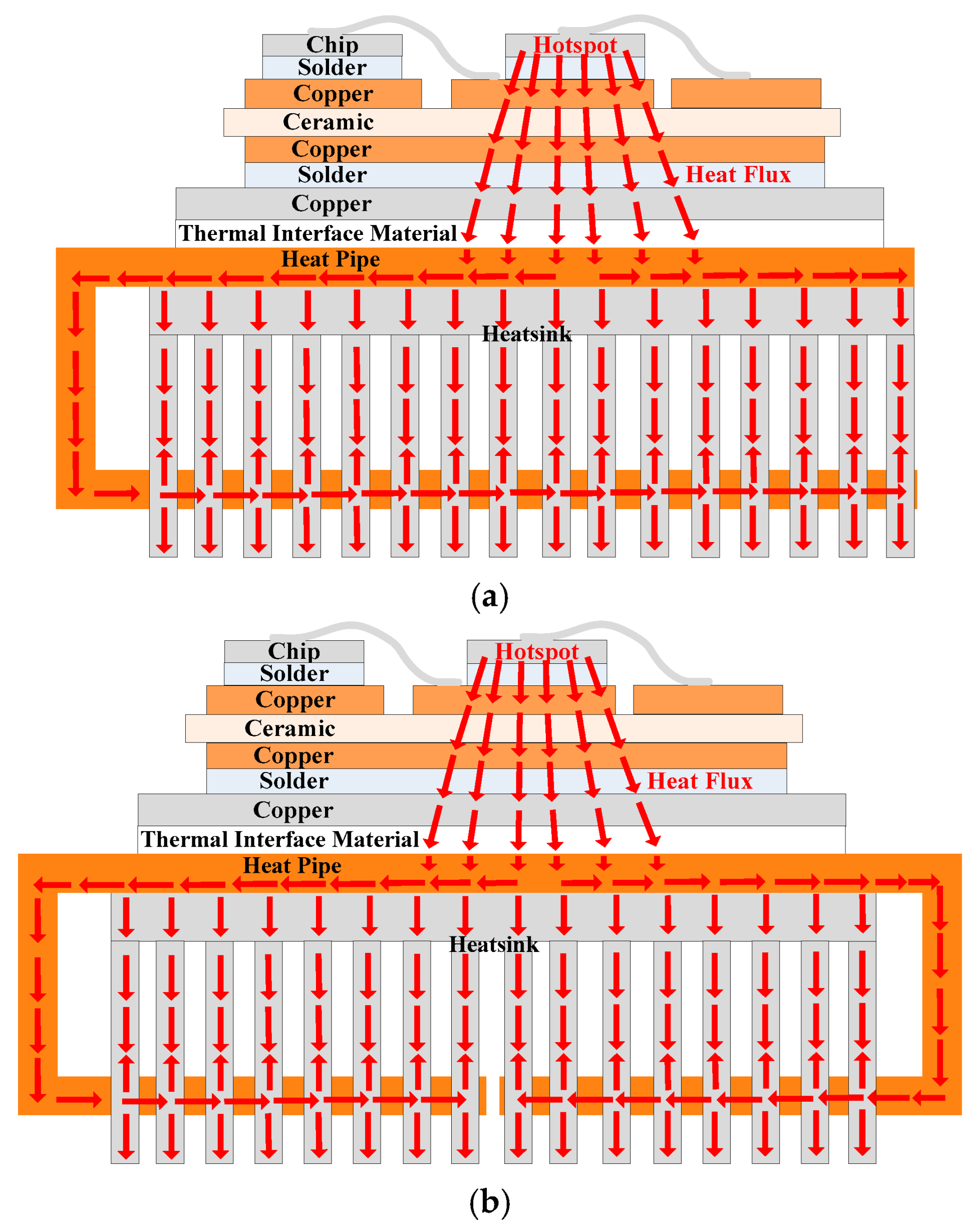
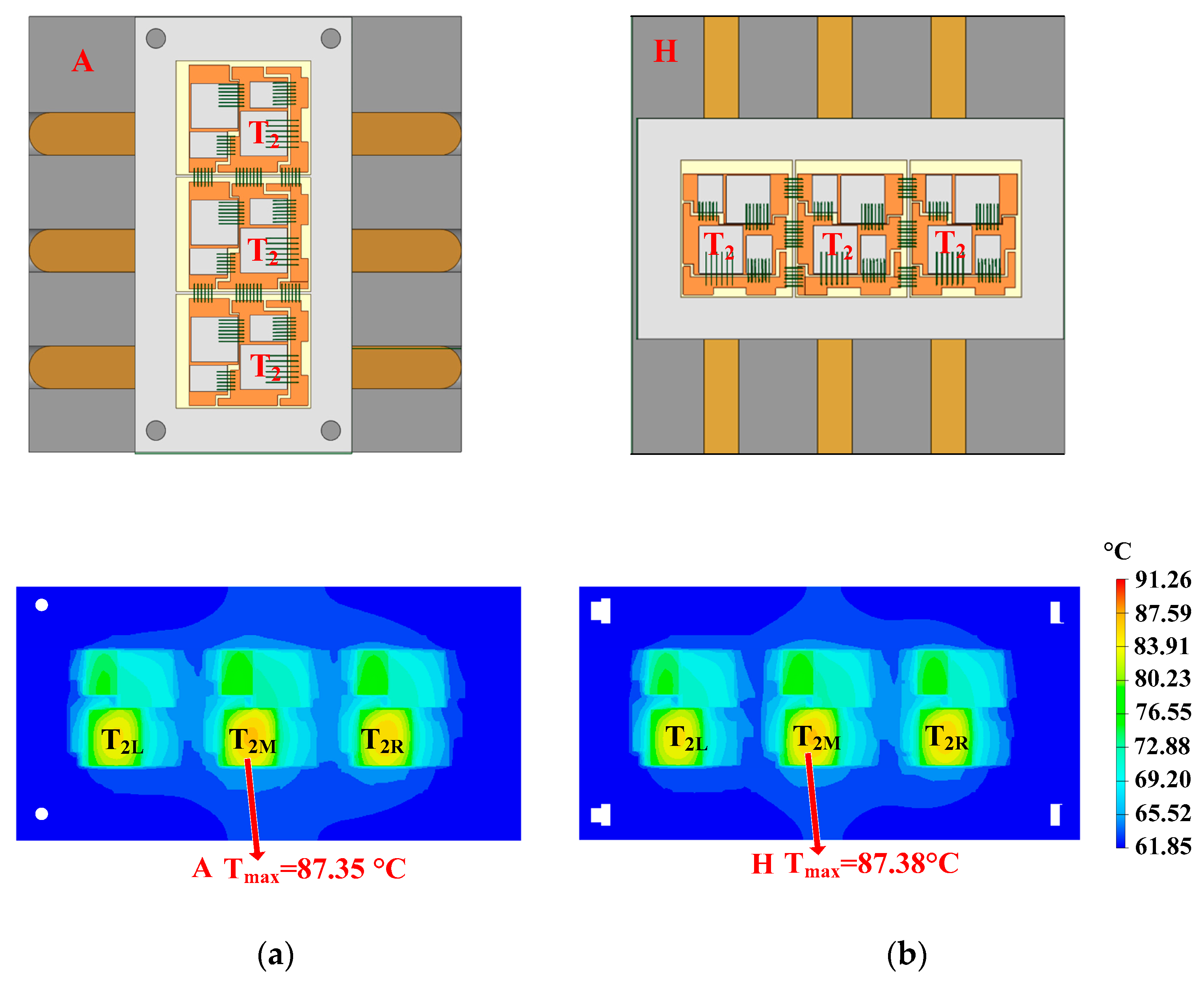
- Direction: Direction here refers to the positional relationship between the heat pipe and the heatsink’s fins. The first positional relationship is that the heat pipe is perpendicular to the fins. Another positional relationship is that the heat pipe is parallel to the fins. Moreover, the direction of the straight heat pipe has little effect on heat flux reconstruction.
- (1)
- Diameter: Heat pipes with a diameter of more than 10 mm have high mechanical strength and are not easy to bend. Even if force is applied to bend them, the capillary structure at the bent part will be damaged, thereby reducing heat transfer performance and being unfavorable for subsequent special-shaped design.
- (2)
- Length: The length of the straight heat pipe should not be greater than the side length of the heatsink.
- (3)
2.4. Research on Special-Shaped Design of Heat Pipes
2.5. Convenient Optimization Method for Heat Pipe Heatsinks
3. Case Study
3.1. Description of the MMC System
3.2. Situation of Using Conventional Heatsinks (Control Group)
3.3. Parameters Optimization of Straight Heat Pipes
- (1)
- Position
- (2)
- Diameter
- (3)
- Quantity
- (4)
- Length
- (5)
- Direction
3.4. Special-Shaped Design of Heat Pipes
4. Experiment
5. Conclusions
- (1)
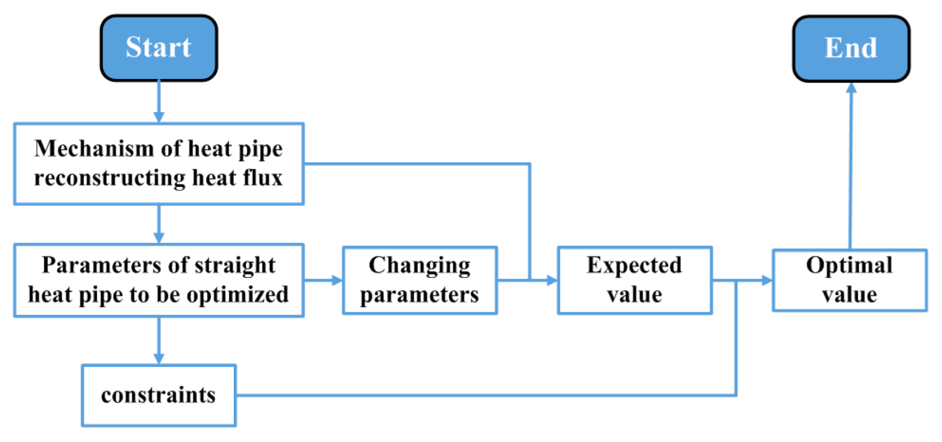
- The position, diameter, quantity, length, and direction of the heat pipes are the parameters to be optimized.
- (2)
- A. The horizontal distance between the heat pipe axis and the hotspot chip axis is supposed to be 0.B. The heat pipes are expected to have the maximum possible thickness.C. The quantity of the heat pipes is expected to be the same as that of the hotspot chips.D. The heat pipes should have the maximum possible length.
- (3)
- There are also some constraints with respect to diameter, length, and direction. The heat pipe’s diameter should not be greater than 10 mm. The length of the straight heat pipe should not be greater than the side length of the heatsink. The heat pipes should be perpendicular to the fins.
- (4)
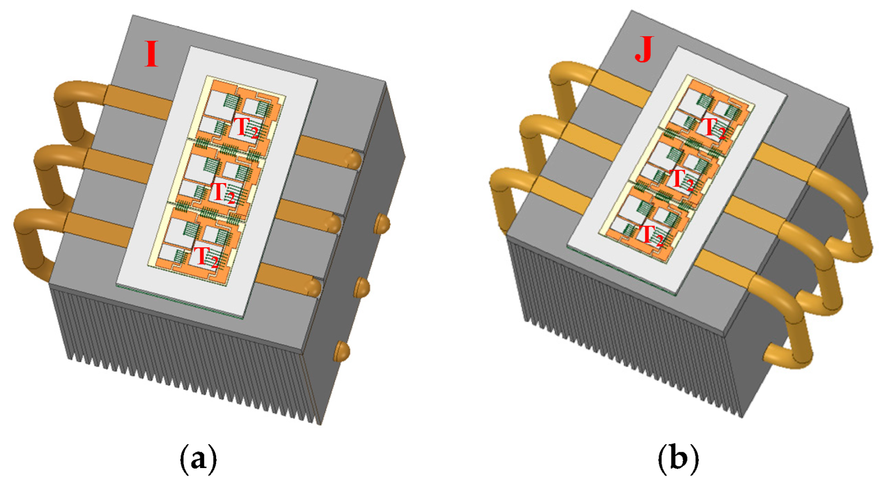
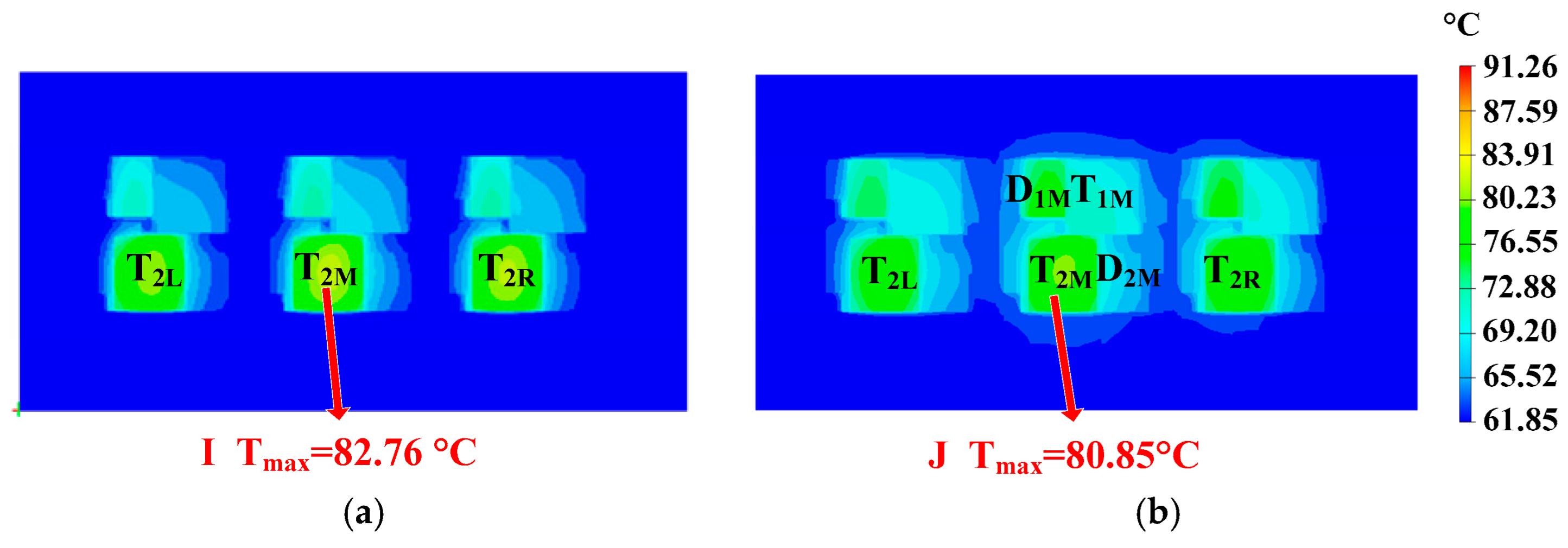
- Designing special-shaped heat pipes can further reduce the thermal resistance of heatsinks by adding parallel thermal resistance to the existing thermal path. Among them, the C-shaped heat pipe has the best cooling effect.
Author Contributions
Funding
Data Availability Statement
Conflicts of Interest
References
- Senemmar, S.; Badakhshan, S.; Zhang, J. Dynamic Modeling and Simulation of Thermal-Electrical Energy Systems in MVDC All-Electric Ships with Small Modular Reactors. In Proceedings of the 2023 IEEE Electric Ship Technologies Symposium (ESTS), Alexandria, VA, USA, 1–4 August 2023; pp. 161–166. [Google Scholar] [CrossRef]
- Chen, W.; Tai, K.; Lau, M.; Abdelhakim, A.; Chan, R.R.; Adnanes, A.K.; Tjahjowidodo, T. Data-Driven Propulsion Load Profile Prediction for All-Electric Ships. In Proceedings of the 2022 International Conference on Electrical, Computer, Communications and Mechatronics Engineering (ICECCME), Malé, Maldives, 16–18 November 2022; pp. 1–9. [Google Scholar] [CrossRef]
- Available online: http://finance.sina.com.cn/jjxw/2022-04-28/doc-imcwipii6928663.shtml (accessed on 16 September 2025).
- Xu, B.; Tu, L.; Gong, S.; Wang, G.; Gao, C.; He, Z. Component-Level Semiconductor Loss Balancing for IGBT Based High Power MMC Through Insertion Index Modification. IEEE Trans. Power Electron. 2022, 37, 14781–14794. [Google Scholar] [CrossRef]
- Wu, T.; Wang, Z.; Ozpineci, B.; Chinthavali, M.; Campbell, S. Automated Heatsink Optimization for Air-Cooled Power Semiconductor Modules. IEEE Trans. Power Electron. 2019, 34, 5027–5031. [Google Scholar] [CrossRef]
- Li, S.; Chen, L.; Yang, P.; Wang, K.; Zheng, Z.; Li, Y. System Control Strategy of an MMC-Based PMSG Rectifier for Ship MVDC Integrated Power System. In Proceedings of the 2019 IEEE Electric Ship Technologies Symposium (ESTS), Washington, DC, USA, 14–16 August 2019; pp. 195–200. [Google Scholar] [CrossRef]
- Long, W.; Liu, N.; Wang, K.; Xu, X.; Zheng, Z.; Li, Y. A Modular Multilevel Converter with Integrated Composite Energy Storage for Ship MVDC Electric Propulsion System. In Proceedings of the 2020 IEEE 9th International Power Electronics and Motion Control Conference (IPEMC2020-ECCE Asia), Nanjing, China, 29 November–2 December 2020; pp. 824–829. [Google Scholar] [CrossRef]
- Wang, B.; Wang, L.; Wu, S.; Hou, Z.; Mu, W.; Yang, F.; Liu, J.; Gan, Y. An Evaluation on Thermal Performance Improvements for SiC Power Module Integrated With Vapor Chamber in MMC. IEEE J. Emerg. Sel. Top. Power Electron. 2022, 10, 5214–5225. [Google Scholar] [CrossRef]
- Available online: https://www.siemens.com/us/en/products/drives/sinamics-electric-drives/perfect-harmony/sinamics-perfect-harmony-gh150-air-cooled-drive.html (accessed on 16 September 2025).
- Pan, J.; Ke, Z.; Al Sabbagh, M.; Li, H.; Potty, K.A.; Perdikakis, W.; Na, R.; Zhang, J.; Wang, J.; Xu, L. 7-kV 1-MVA SiC-Based Modular Multilevel Converter Prototype for Medium-Voltage Electric Machine Drives. IEEE Trans. Power Electron. 2020, 35, 10137–10149. [Google Scholar] [CrossRef]
- Lin, H.; Wang, Z.; Guo, X.; Lin, Z.; Chen, G. A 380 V/50 kVar SiC-SVG Achieving a Power Density of 1.652 kVar/L with the Optimization of Heatsink and Output Filter Volume. IEEE J. Emerg. Sel. Top. Power Electron. 2022, 10, 4634–4649. [Google Scholar] [CrossRef]
- Vogel, M.; Xu, G.; Copeland, D.; Kang, S.; Whitney, B.; Meyer, G.; Kawabata, K.; Conners, M. Low profile heat pipe heat sink and green performance characterization for next generation CPU module thermal designs. In Proceedings of the 2010 26th Annual IEEE Semiconductor Thermal Measurement and Management Symposium (SEMI-THERM), Santa Clara, CA, USA, 21–25 February 2010; pp. 145–150. [Google Scholar]
- Mansouri, N.; Weasner, C.; Zaghlol, A. Characterization of a Heat Sink with Embedded Heat Pipe with Variable Heat Dissipating Source Placement for Power Electronics Applications. In Proceedings of the 2018 17th IEEE Intersociety Conference on Thermal and Thermomechanical Phenomena in Electronic Systems (ITherm), San Diego, CA, USA, 29 May–1 June 2018; pp. 311–317. [Google Scholar]
- Mansouri, N.; Zaghlol, A.; Weasner, C. Characterization of an Embedded Heat Pipe Heat Sink for Multiple Heat Sources for Power Electronics Applications. In Proceedings of the 2019 18th IEEE Intersociety Conference on Thermal and Thermomechanical Phenomena in Electronic Systems (ITherm), Las Vegas, NV, USA, 28–31 May 2019; pp. 675–683. [Google Scholar]
- Han, C.W.; Sung, S.C.; Choi, K.M. Statistical Analysis of the Thermal Performance and Reliability in the Heat Sink with Heat Pipes for the Power Electronics Module. IEEE Trans. Compon. Packag. Manuf. Technol. 2022, 12, 59–68. [Google Scholar] [CrossRef]
- Driss, A.; Maalej, S.; Zaghdoudi, M.C. Electro-thermal modeling of power IGBT modules by heat pipe systems. In Proceedings of the 2017 International Conference on Engineering & MIS (ICEMIS), Monastir, Tunisia, 8–10 May 2017; pp. 1–7. [Google Scholar]
- Driss, A.; Maalej, S.; Zaghdoudi, M.C. Thermal simulation approach to the cooling of a power IGBT by heat pipes. In Proceedings of the 2013 5th International Conference on Modeling, Simulation and Applied Optimization (ICMSAO), Hammamet, Tunisia, 28–30 April 2013; pp. 1–6. [Google Scholar]
- Mansouri, N.; Zaghlol, A.; Weasner, C. Force Convection Performance of the Heat Sink with Embedded Heat Pipes Comparing Two Embedding Technologies for Heat Pipes. In Proceedings of the 2020 19th IEEE Intersociety Conference on Thermal and Thermomechanical Phenomena in Electronic Systems (ITherm), Orlando, FL, USA, 21–23 July 2020; pp. 8–14. [Google Scholar]
- Cui, H.; Hu, F.; Zhang, Y.; Zhou, K. Heat spreading path optimization of IGBT thermal network model. Microelectron. Reliab. 2019, 103, 113511. [Google Scholar] [CrossRef]
- Yu, X.; Liu, Z.; Feng, Q.; Wei, Y.; Wang, J. Research on a gravity heat pipe for high voltage vacuum interrupter. In Proceedings of the 2008 23rd International Symposium on Discharges and Electrical Insulation in Vacuum, Bucharest, Romania, 15–19 September 2008; pp. 129–132. [Google Scholar]
- Wrobel, R.; McGlen, R.J. Opportunities and Challenges of Employing Heat-Pipes in Thermal Management of Electrical Machines. In Proceedings of the 2020 International Conference on Electrical Machines (ICEM), Gothenburg, Sweden, 23–26 August 2020; pp. 961–967. [Google Scholar]
- Lv, Y.; Li, T.; Ye, Y.; Tu, Z.; Li, L. Experimental and Simulation Study on Fast Cooling Method of Pulsed Magnetic Coil Based on Heat Pipe. IEEE Trans. Appl. Supercond. 2024, 34, 4300906. [Google Scholar] [CrossRef]
- Sheng, J.; Yang, H.; Li, C.; Chen, M.; Li, W.; He, X.; Gu, X. Active thermal control for hybrid modular multilevel converter under overmodulation operation. IEEE Trans. Power Electron. 2020, 35, 4242–4255. [Google Scholar] [CrossRef]
- Qiu, H.; Wang, J.; Tu, P.; Tang, Y. Device-level loss balancing control for modular multilevel converters. IEEE Trans. Power Electron. 2021, 36, 4778–4790. [Google Scholar] [CrossRef]
- Mao, H.; Jiang, H.; Ran, L.; Hu, J.; Qiu, G.; Wei, J.; Chen, H.; Zhong, X.; Xiao, N.; Wang, L.; et al. An asymmetrical power module design for modular multilevel converter with unidirectional power flow. IEEE Trans. Power Electron. 2023, 38, 1092–1103. [Google Scholar] [CrossRef]
- Wang, L.; Xu, J.; Wang, G.; Zhang, Z. Lifetime estimation of IGBT modules for MMC-HVDC application. Microelectron. Rel. 2018, 82, 90–99. [Google Scholar] [CrossRef]
- Zhang, Y.; Wang, H.; Wang, Z.; Blaabjerg, F.; Saeedifard, M. Mission Profile-Based System-Level Reliability Prediction Method for Modular Multilevel Converters. IEEE Trans. Power Electron. 2020, 35, 6916–6930. [Google Scholar] [CrossRef]
- Yang, J. Icepak FAQ in V1.0 beta. Tech. Rep. 2008, pp. 8–9. Available online: https://wenku.baidu.com/view/969dd44be45c3b3567ec8bf6.html (accessed on 16 September 2025).
- Li, D.; Zhang, G.Q.; Pan, K.; Ma, X.; Liu, L.; Cao, J. Numerical simulation on heat pipe for high power LED multi-chip module packaging. In Proceedings of the 2009 International Conference on Electronic Packaging Technology & High Density Packaging, Beijing, China, 10–13 August 2009; pp. 393–397. [Google Scholar]
- Liu, Y.; Dong, K.; Dong, T. Thermal simulation of bionic transpiration heat pipe system for high-power LED. In Proceedings of the 16th International Conference on Mechatronics-Mechatronika 2014, Brno, Czech Republic, 3–5 December 2014; pp. 688–692. [Google Scholar]
- Fabis, P.M.; Shun, D.; Windischmann, H. Thermal modeling of diamond-based power electronics package. In Proceedings of the Fifteenth Annual IEEE Semiconductor Thermal Measurement and Management Symposium (Cat. No.99CH36306), San Diego, CA, USA, 9–11 March 1999; pp. 98–104. [Google Scholar]









| Symbol | Meaning | Value |
|---|---|---|
| P | System-rated active power | 1.3 MW |
| Udc | DC-link voltage | 4.5 kV |
| Um | Amplitude of ac-side phase voltage | 2 kV |
| N | Number of SMs | 5 |
| L | Arm inductor | 5 mH |
| cosφ | Power factor | 0.9 |
| C | SM capacitor | 4.7 mF |
| fs | Switching frequency | 1 k Hz |
| f | Fundamental frequency | 50 Hz |
| Component | Material | Thermal Conductivity (W/K·m) | Thickness (mm) | CTE (10−6/K) |
|---|---|---|---|---|
| Chip | Silicon | 130 | 0.2 | 3 |
| Chip solder | SAC305 | 66 | 0.12 | 23 |
| Upper cooper | Copper | 385 | 0.3 | 17 |
| Ceramic | Alumina | 25 | 0.38 | 7 |
| Bottom copper | Copper | 385 | 0.3 | 17 |
| DBC solder | SAC305 | 66 | 0.12 | 23 |
| Baseplate | Copper | 385 | 3 | 17 |
| TIM | Silicone grease | 5 | 0.1 | / |
| Heatsink base | Aluminum alloy | 201 | 12 mm | 23 |
| Heatsink fins | Aluminum alloy | 226 | 1.75 mm | 24 |
| Parameters | Value (Explanation) |
|---|---|
| Position | Directly under the hotspot chip |
| Diameter | 10 mm |
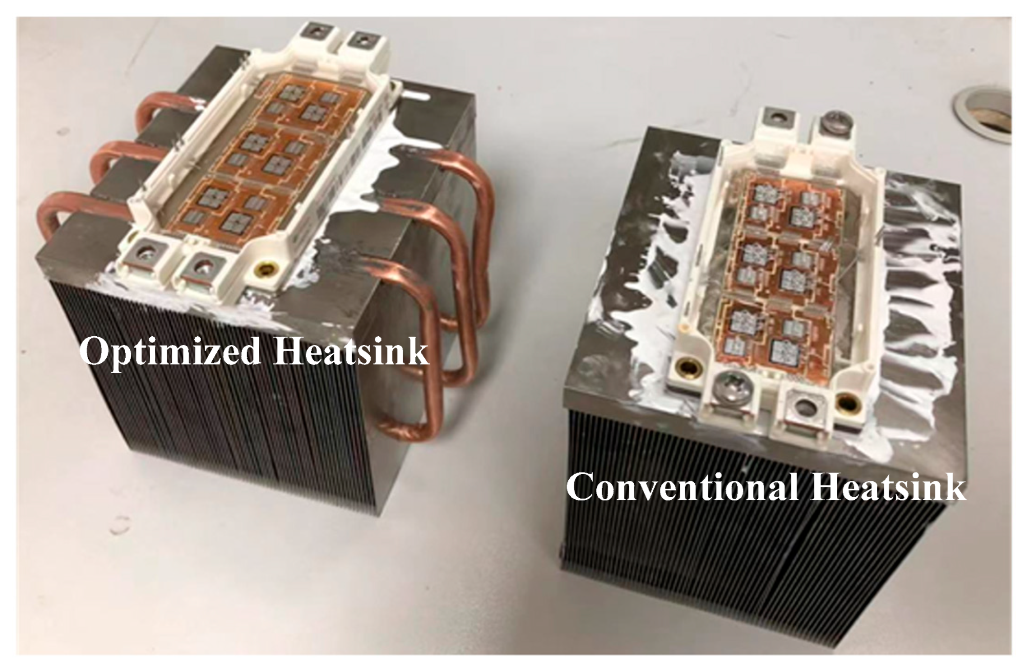
| Quantity | 3 (same as the number of the hotspot chips) |
| Length | 122 mm (same as the side length of the heatsink) |
| Direction | Perpendicular to the fins |
Disclaimer/Publisher’s Note: The statements, opinions and data contained in all publications are solely those of the individual author(s) and contributor(s) and not of MDPI and/or the editor(s). MDPI and/or the editor(s) disclaim responsibility for any injury to people or property resulting from any ideas, methods, instructions or products referred to in the content. |
© 2025 by the authors. Licensee MDPI, Basel, Switzerland. This article is an open access article distributed under the terms and conditions of the Creative Commons Attribution (CC BY) license (https://creativecommons.org/licenses/by/4.0/).
Share and Cite
Wang, B.; Lu, T.; Wu, Q.; Yao, B.; Zhang, H.; Zhou, X.; Liu, W. An Enhanced Cooling Method for Power Modules on All-Electric Ships Based on Parameter Optimization and Special-Shaped Design of Sintered Heat Pipes. Micromachines 2025, 16, 1197. https://doi.org/10.3390/mi16111197
Wang B, Lu T, Wu Q, Yao B, Zhang H, Zhou X, Liu W. An Enhanced Cooling Method for Power Modules on All-Electric Ships Based on Parameter Optimization and Special-Shaped Design of Sintered Heat Pipes. Micromachines. 2025; 16(11):1197. https://doi.org/10.3390/mi16111197
Chicago/Turabian StyleWang, Binyu, Ting Lu, Qisheng Wu, Bobin Yao, Hongwei Zhang, Xiwei Zhou, and Weiyu Liu. 2025. "An Enhanced Cooling Method for Power Modules on All-Electric Ships Based on Parameter Optimization and Special-Shaped Design of Sintered Heat Pipes" Micromachines 16, no. 11: 1197. https://doi.org/10.3390/mi16111197
APA StyleWang, B., Lu, T., Wu, Q., Yao, B., Zhang, H., Zhou, X., & Liu, W. (2025). An Enhanced Cooling Method for Power Modules on All-Electric Ships Based on Parameter Optimization and Special-Shaped Design of Sintered Heat Pipes. Micromachines, 16(11), 1197. https://doi.org/10.3390/mi16111197


