Abstract
Laser trepan drilling and laser helical drilling are typical methods for fabrication of micro through-holes through scanning laser beam. In the drilling process, the subsequent laser pulse may be occluded by the edge and the sputter deposition at the edge of the previous drilled trench. Dynamic focus feeding and widening path can be employed to lessen the occlusion effect and both of them are always employed in laser helical drilling. However, Widening the trench needs to remove more volume of material and may bring certain negative effects such as lowering the recoil pressure as well as less splashing melt due to the limited constraint of trench wall. The effects of dynamic feeding the focal plane and widening the scanning path on the quality and efficiency in the nanosecond laser drilling process were investigated through laser drilling holes with diameter of 500 μm on a 300 μm thick GH4169 plate. Results show that dynamic focus feeding is beneficial in both drilling efficiency and drilling quality. Through laser helical drilling with dynamic focus feeding, micro through-hole can be fabricated in 5 s, and both smaller tilting angle of 0.073 rad and smaller heat-affected zone of 0.63 mm in radius can be obtained. Widening scanning path is helpful to perforating rapidly but leads to much more recast layer coating. the quality of the micro through-holes depends not only on the utilization efficiency of the laser energy, but also on high temperature spatter deposition, which is the source of the difference between different drilling strategies. Due to the low cost in equipment and the better hole quality, the laser drilling, especially laser helical drilling, has potential applications ranging from aerospace fields to normal fields such as the agricultural machinery industry.
1. Introduction
In many mechanical devices, micro through-holes are a typical structure that is broadly used to control fluids flow [1,2,3,4,5]. In some high-end applications, both the high-quality requirements of micro through-holes and the requirements for high-performance materials call for reasonable machining technology for micro through-holes [6,7,8]. In order to process such through-holes, some nontraditional machining technologies such as electrochemical machining (ECM), electrical discharge machining (EDM) [9,10] and three-dimensional printing [11] have been employed in the industry. However, in these methods, the material should be suitable to the corresponding technology, and the shape of the through-holes depends on the tool shape which in turn is affected by the process. In such a context, laser drilling becomes a promising process for micro through-holes fabrication due to its advantages of non-contact characteristics, non-wear characteristics, and non-material selection characteristics [12,13,14,15].
At present, the single-pulse laser drilling [16,17], laser percussion drilling [18,19], laser trepan drilling [20,21] and laser helical drilling [22,23] have been developed. Once combined with femtosecond laser, these methods can be used to realize good hole shape and surface quality of hole wall [24,25,26]. Among these methods, laser trepan drilling [27,28] is an effective method to fabricate through-holes by melting less sputtering material, as shown in Figure 1. In laser trepan drilling, only the material within the path traveled by the laser is melted, and most of the material in the hole is removed in a solid form. Therefore, such a method is suitable to fabricate through-holes with larger diameter such as those in sprinkler [29,30,31] and can realize better inner wall surface quality. However, due to both the narrow scanning path and the fact that the laser focal plane remains unchanged during the machining process (the material to be melted cannot always keep in the beam focal plane), the efficiency of the successive processing stage is reduced [32,33], i.e., both the edge of the machined micro trench and the deposition of sputter to the edge of the trench reduces the laser energy access to the bottom of the trench (occlusion effect), as shown in Figure 2. This effect limits both the depth of the hole and the quality of the machined hole, which limits the application of laser trepan drilling in manufacturing through-holes such as nozzles of sprinklers [34,35,36]. Therefore, it is necessary to further explore and improve the process to improve the performance of the laser processing process.
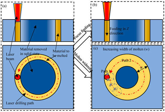
Figure 1.
Schematic of the laser trepan drilling (a), laser helical drilling (b), and laser trepan drilling by widening the laser path (c).
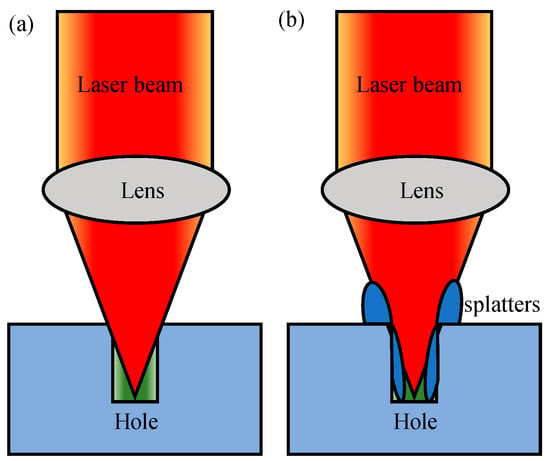
Figure 2.
Schematic of the occlusion effect of trench edge (a) and the deposition of sputter to the edge of the trench (b).
To improve the efficiency of laser trepan drilling, one approach is to dynamically feed the position of the laser focal plane [37,38,39] (Figure 1b) at the right time, so that the material to be melted keeps at a high-intensity laser irradiation position. However, feeding the focal plane’s position requires adjusting the distance between the focusing lens and the sample, which should be realized synchronously with the scanning operation of the galvanometer. Recently, by placing the focusing lens on the front [40,41], it is possible to synchronously control both the focusing lens and the galvanometer scanner, i.e., laser helical drilling. The use of this system is expected to improve the efficiency of hole drilling. To relieve the occlusion effect of both the trench edge and the deposition, another way is to widen the width of the trench to be machined [42,43] (Figure 1c). Widening the trench can be achieved by scanning a series of overlapping circles or scanning a series of nested circles. To improve the efficiency of laser helical drilling, both feeding the focal plane and widening the trench were used in most former works [8,25] even drilling holes on thin samples [44]. Although widening the trench is helpful in avoiding occlusion effect, more volume of material needs to be removed. Moreover, widening the trench may bring certain negative effects in machining thinner plates, such as those in Ref. [44], e.g., lowering the recoil pressure as well as less splashing melt due to limited constraint of trench wall. In this paper, we will study the effect of dynamic focus feeding and widening trench on the laser trepan drilling in laser drilling micro through-holes on a GH4169 plate with thickness of 300 μm.
In laser drilling, although femtosecond laser can achieve better processing results [8,25,45,46,47,48,49], femtosecond laser is a typical processing with high investment, difficult maintenance, and low processing efficiency. As a low-cost equipment, nanosecond laser [50,51,52] and/or longer pulsed laser [53,54] even CW laser [55] is widely used in the industrial field and scientific research. However, the laser drilling with nanosecond laser is easy to cause serious recast layers and heat-affected zones especially in single-pulse and percussion drilling [56,57]. Such serious recast layers and heat-affected zones may limit the application of laser drilling in fabrication of some special nozzles [58,59,60]. If the recast layer and heat-affected zone can be effectively controlled, nanosecond laser will be more widely used in drilling through-holes on high-performance materials. For this reason, we investigate the effects of dynamic feeding the focal plane and widening the scanning path on the quality and efficiency in the nanosecond laser drilling process.
The nanosecond laser is used to drill holes on a 300 μm thick GH4169 plate. The micro through-holes are drilled by four processes, namely laser trepan drilling, laser helical drilling, laser trepan drilling with widening path and laser helical drilling with widening path. The diameter of the micro through-holes to be prepared is set at 500 μm. The deviation between the fabricated hole size and the ideal hole size, the hole morphology at the entrance end and the exit end, and the size of the heat-affected zone at the edge of the micro through-holes were analyzed.
2. Materials and Methods
The laser drilling experiments were carried out on GH4169 superalloy plate (the chemical composition is shown in Table 1) with dimensions of 20 mm × 20 mm × 0.3 mm. The workpiece was fixed on an X–Y–Z stage. The laser drilling experiments were performed using a Nd:YVO4 nanosecond laser at a wavelength of 532 nm and a pulse duration of 12 ns. The laser power, repetition rate, and scanning velocity were set as 20 W, 100 kHz, and 500 mm/s, respectively. The laser spot diameter is about 45 μm. As nanosecond laser drilling is a typical thermal process, the repetition rate of 100 kHz was chosen with reference to femtosecond laser drilling [8,25] although which may lead to certain thermal effect [61].

Table 1.
Chemical composition of GH4169.
Four types of laser drilling were investigated, i.e., laser trepan drilling, laser helical drilling, laser trepan drilling with widening path, and laser helical drilling with widening path, as schematic shown in Figure 3. In laser trepan drilling (Figure 3a), the laser beam moves along the outline of the micro-hole to be fabricated, and the material is removed through the scanning path to penetrate the workpiece. In the whole process, the focal plane of the laser beam remained the same. In laser helical drilling (Figure 3b), a 3D dynamic focusing system was used to realize reasonable dynamic focus along the Z axis. Combining the scanning operation and the dynamic focusing, the laser beam focus scans the material with a helical path. In laser trepan drilling with widening path (Figure 3c), the laser scans the material starting from the circular path 180 μm inward from the final outline of the micro-hole (i.e., w = 180 μm), while the focal plane of the laser beam remained the same. To widen the laser scanning path, five scanning paths with 45 μm spacing between paths were filled. Through this method, the laser is used to direct remove a 180 μm ring. In laser helical drilling with widening path (Figure 3d), the laser also scans the material starting from the circular path 180 μm inward from the final outline of the micro-hole and the focal plane is fed dynamically. In the drilling experiments, compressed air was used to blow away molten or vaporized material. All experiments were performed in air, and holes were drilled vertically at 90° to the workpiece.
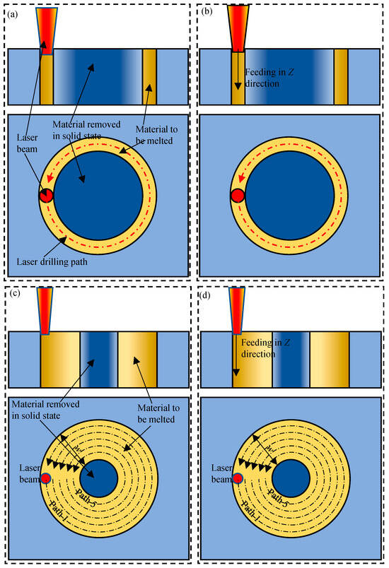
Figure 3.
Schematic of (a) laser trepan drilling, (b) laser helical drilling, (c) laser trepan drilling with widening path, and (d) laser helical drilling with widening path.
After laser drilling, the morphology of both the entrance end and the exit end of the holes were examined by scanning electron microscopy (SEM) (SEM, FEI, Eindhoven, The Netherlands). The heat affected zone was investigated through a BX60M optical microscopy (Olympus, Tokyo, Japan).
3. Results
Four types of laser drilling were investigated by scanning electron microscopy. The parameters of the micro through-holes were measured from these SEM images. And the morphology on the SEM image were analyzed qualitatively.
3.1. Morphology of Micro Through-Holes Fabricated by Laser Drilling
3.1.1. Laser Trepan Drilling
Figure 4 shows the surface morphology at the entrance end and the exit end of the holes achieved by laser trepan drilling. It can be seen that after 5 s of processing, the solid material in the center of the micro holes did not fall off. And there was more material adhesion at the exit end of the micro holes (Figure 4b), making it difficult to remove the central material. After 11 s of processing (Figure 4c), the central material fell off, but sputters could be seen at the edge of the hole. And there was obviously material that had not been removed at the exit end of the hole, and the exit end of the hole was adhered to some recast layer.
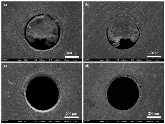
Figure 4.
The SEM image of micro through-holes fabricated by laser trepan drilling. (a) The entrance end after drilling 5 s, (b) The exit end after drilling 5 s, (c) The entrance end after drilling 11 s, (d) The exit end after drilling 11 s.
3.1.2. Laser Helical Drilling
Figure 5 shows the micro hole morphology achieved by laser helical drilling. It can be seen that after 5 s of processing, the solid material in the center of the micro holes has been completely shed (Figure 5a), and only some material remains at the exit end of the micro holes (Figure 5b). After 12 s of processing (Figure 5c), the quality of the hole shape is improved, there is less sputter at the edge of the hole. There is no obvious material residue at the exit end of the micro hole (Figure 5d). The shape of the micro hole at the exit end is similar to that at the entrance end, indicating that the taper of the hole wall is effectively controlled. It can be seen that both the processing efficiency and quality of micro through-holes have been greatly improved by controlling the position of the laser beam focus (focusing lens position).
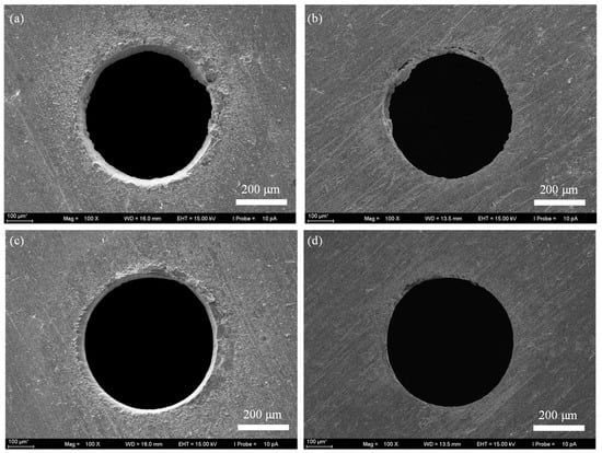
Figure 5.
The SEM image of micro through-holes fabricated by laser helical drilling. (a) The entrance end after drilling 5 s, (b) The exit end after drilling 5 s, (c) The entrance end after drilling 12 s, (d) The exit end after drilling 12 s.
3.1.3. Laser Trepan Drilling with Widening Path
Figure 6 shows the micro holes morphology achieved by laser trepan drilling with widening path. It can be seen that for the 3 s machining, the solid material in the center of the micro holes has generally fallen off (Figure 6a), but there is a large amount of material residue at the entrance end and exit end of the micro holes (Figure 6a,b). For machining 6 s, the sputter of the holes was effectively removed (Figure 6c), and both the radius of the micro hole at the entrance end and the exit end increased (Figure 6c,d). After 15 s of processing (Figure 6e), the hole shape quality is improved, and the spatter at the edge of the micro hole is reduced, but the attachment of the recast layer is clearly visible at both the entrance end and the exit end of the micro hole (Figure 6e,f). These results indicate that increasing the width of the trench by controlling the scanning path of the laser beam does not achieve the ideal processing quality.
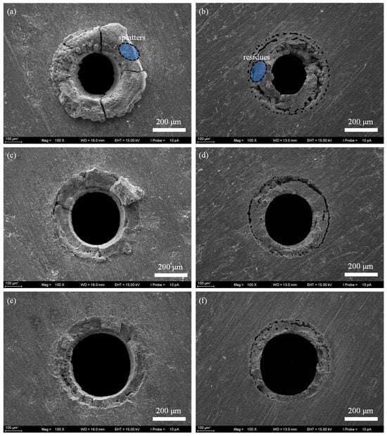
Figure 6.
The SEM image of micro through-holes fabricated by laser trepan drilling with widening path. (a) The entrance end after drilling 3 s, (b) The exit end after drilling 3 s, (c) The entrance end after drilling 6 s, (d) The exit end after drilling 6 s, (e) The entrance end after drilling 15 s, (f) The exit end after drilling 15 s.
3.1.4. Laser Helical Drilling with Widening Path
Figure 7 shows the micro holes morphology achieved by laser helical drilling with widening path. After 3 s laser drilling, the material at the center of the hole is effectively removed. However, there were more splatters left at the edge of the micro hole (Figure 7a,b), while the residue at the exit end of the hole was difficult to remove. Even after 8 s laser drilling, both the splatters and residue remain (Figure 7c,d). And some microscopic holes appeared at the edge (Figure 7b,d), indicating that laser helical drilling with widening path cannot achieve an ideal result.
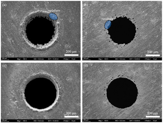
Figure 7.
The SEM image of micro through-holes fabricated by laser helical drilling with widening path. (a) The entrance end after drilling 3 s, (b) The exit end after drilling 3 s, (c) The entrance end after drilling 8 s, (d) The exit end after drilling 8 s.
3.2. Comparison of the Micro Hole Parameters in Different Laser Drilling
Figure 8a shows the diameter of micro holes at both the entrance end and the exit end in different laser drilling methods. The diameter of micro holes at both the entrance end in four types of laser drilling are, respectively, 538.2 ± 5.5 μm, 544.7 ± 2.7 μm, 412.2 ± 10.6 μm, and 524.9 ± 4.0 μm. Except that in laser helical drilling (544.7 ± 2.7 μm), the hole diameters especially in the case of widening the path are significantly different from the expected results (500 + 45 μm). The diameter of micro holes at both the entrance end in four types of laser drilling are, respectively, 461.6 ± 10.4 μm, 501.0 ± 6.1 μm, 366.5 ± 13.3 μm, and 443.6 ± 2.7 μm. It can be seen that the laser helical drilling brings the better results, i.e., the diameter of the micro holes at the entrance end and the exit end are close to the anticipated value of 500 + 45 μm and the difference between them is the less. Both the widening path experiments did not lead to reasonable results, which is even worse than that from the laser trepan drilling.

Figure 8.
The parameters of micro holes at both the entrance end and the exit end in different laser drilling methods. (a) Diameter of micro hole at the entrance end and the exit end; (b) Tilting angle of the hole wall.
Figure 8b shows the tilting angle of the micro hole wall. The tilting angle α is calculated by α = arctan ((D1 − D2)/(2h)), where D1 and D2 are the diameter of the hole at the entrance end and the exit end, and h is the thickness of the sample [25]. In the initial stage, the tilting angles in four types of laser drilling are, respectively, 0.091 rad (only evaluated from the local profile of the scanning path), 0.103 rad, 0.103 rad, 0.197 rad. In the final stage, the tilting angles change to be 0.127 rad, 0.073 rad, 0.076 rad, 0.135 rad. It can be seen again that the best result is obtained from laser helical drilling, which is close to the value of holes fabricated by femtosecond laser drilling [8,25]. Although the laser trepan drilling with widening path realizes a letter tilting angle, one should keep in mind that such a small tilting angle is an illusion of the recast layer coated on the hole wall.
3.3. Comparison of the Heat Affected Zone in Different Laser Drilling
The method of laser drilling not only affects the quality of the hole and the residue of spatter but also affects the heat-affected zone due to the difference in the residue of the spatter and the heating process. Figure 9 and Figure 10 show the typical heat-affected zone size determined by different laser drilling methods.
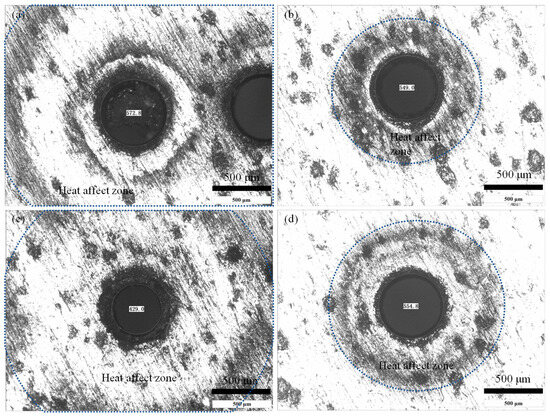
Figure 9.
The heat affect zone in laser drilling. (a) Laser trepan drilling, (b) Laser helical drilling, (c) Laser trepan drilling with widening path, and (d) Laser helical drilling with widening path.
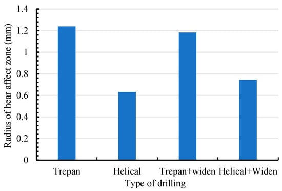
Figure 10.
The radius of heat affect zone in laser drilling.
It can be seen that for the case of laser trepan drilling (Figure 9a) the heat-affected zone is large (1.24 mm in radius). Because during most of the process, the material is not exactly in the laser beam focal plane, the utilization efficiency of the laser energy in material removal is low, and part of the laser energy propagates into the material near the ablated area. Moreover, poor evaporation and splashing conditions cause high temperature sputters to be deposited on the surface of the material, which in turn increases the heat-affected zone. For laser helical drilling (Figure 9b), due to the high intensity of the laser beam when it interacts with the material, the laser energy absorbed by the material is mainly used for splashing and evaporation, and less splash residue reduces the heat effect. Therefore, the heat-affected zone is the smallest in this situation (0.63 mm in radius). For laser trepan drilling with widening path (Figure 9c), even if the laser drilling time is short (3 s), the large residue of the melt makes the heat-affected zone larger (1.18 mm in radius, similar to that in laser trepan drilling), which also reflects the poor laser utilization efficiency in this case. Although the heat-affected zone can be improved by feeding the focal plane (Figure 9d), it (0.74 mm in radius) is still worse than that in laser helical drilling (Figure 9b).
4. Discussion
From the above results, one can see that the best quality can be realized by dynamic feeding the laser beam focal plane, while widening the path contributes very little when drilling micro through-holes on a plate with thickness of 0.3 mm. In fact, dynamic feeding the focus is equivalent to widening the trench entrance to a certain degree. Importantly, the utilization efficiency of laser energy in melting and evaporation is increased by dynamic feeding the focus, which contributes to both effects of improving drilling efficiency and lessening heat affected zone. To clarify the effect of dynamic focus feeding and widening path, the mechanisms of laser–matter interaction in different situations are constructed, as shown in Figure 11.
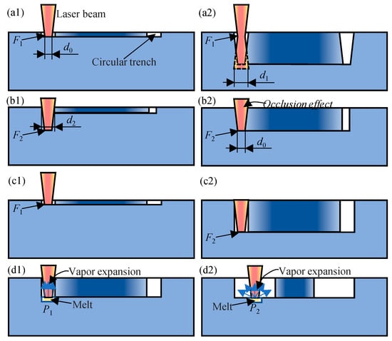
Figure 11.
The schematic of laser–matter interaction in different scenarios. (a1,a2) Fixed laser focus near the surface, (b1,b2) fixed laser focus inside the material, (c1,c2) dynamically feeding the laser focus, and (d1,d2) comparison between the simple helical drilling and that with widening path.
In laser trepan drilling, due to the unchanging focal plane, the utilization efficiency of the laser energy is not very high unless the material to be ablated is exactly in the focal plane. If the focal plane is preset on the material surface (Figure 11a1), the intensity of the subsequent laser pulse is also less due to the defocus effect, i.e., the laser intensity decreases when the diameter of the laser beam at the plane of the material to be ablated increases from d0 to d1 (Figure 11a2). Therefore, the width of the trench decreases gradually. If the focal plane is preset inside the material (Figure 11b1), due to the less laser intensity (a wider laser beam) on the material surface, the entrance of the trench may be too narrow and most of the later laser pulses hardly reach the bottom of the trench due to the occlusion effect (Figure 11b2). Therefore, no matter where the laser beam focus is preset, the efficiency of laser trepan drilling is not very high and thus some recast layer adheres to the exit end of the hole, as shown in Figure 4.
In laser helical drilling process (Figure 11c1), if the material to be processed is in the focal plane (less out of focus), the laser intensity is the largest and thus the laser energy is effectively used for material melting and evaporation. The violent evaporation makes the melt splash more intense, resulting in both the wider entrance of the trench and a decrease in the sputter attached to the edge of the hole. Therefore, the occlusion effect of both the trench edge and the sputter adhered to the edge reduces. These two factors lead to a great improvement in the processing efficiency and quality of micro holes in laser helical drilling (Figure 11c2).
By scanning the laser beam in a wider area, although the width of the trench increased, the volume of melt removed by splashing and evaporation did not increase because the ablation time did not increase proportionally. And the increase in the laser ablation area led to a decrease in the amount of melt removed per unit area. At the same time, although the increase in the trench reduces the occlusion effect of the trench edge on the incident beam, it weakens the laser splash effect due to loss of constraint of trench wall (Figure 11d1,d2). In the simple laser helical drilling, the vapor expanded under constraint of trench wall and thus causes higher recoil pressure (Figure 11d1), while the vapor expansion in a wider space in laser helical drilling with widening path leads to lower recoil pressure (Figure 11d2). In the latter case, the melt, especially under the action of surface tension, is difficult to remove. Therefore, even after 15 s processing, the wall of the micro hole is still coated with a ~50 μm recast layer (formed from melt film on the microhole walls as revealed by high-speed synchrotron x-ray imaging [62]), which limits the application of such micro through-holes (Figure 6). By dynamic feeding the focal plane, the intensity of the laser can be enhanced. However, the wider and asymmetric trench less the self-focus effect of the trench wall on the laser beam, so the laser energy used to remove the material at the exit end of the hole is less. And thus, there was certain residue at the edge of the micro hole (Figure 7). Although widening drilling path does not realize better affect, it is still helpful in perforating rapidly, which may also be used in drilling thick plate and deserves further investigation.
The heat affected zone depends not only on the utilization efficiency of the laser energy, but also on high temperature spatter deposition. Certain models may be constructed based on simulation and experimental works in the future. And the best strategy of the helical path needs further investigation.
In the aerospace field, with the high requirement of combustion temperature, there are high requirements for both materials with better heat resistance and cooling film strategy. This requires micro through-holes with high precision, better surface quality, thinner recasting layers, and small heat-affected zones [63,64,65]. The micro through-holes fabricated by nanosecond laser helical drilling may have applications in these fields.
Due to the low cost of nanosecond laser, the laser trepan drilling and laser helical drilling can also be applied to achieve through-hole preparation in some normal fields such as the agricultural machinery industry. In these field, to improve the performance of nozzle, some special strategies are under investigation [66,67,68]. And employing non-circular nozzles can help drop formation [69,70], and the laser drilling method may be used to replace EDM [71,72] to realize better non-circular nozzles with broad scale.
5. Conclusions
Four nanosecond laser drilling strategies, namely laser trepan drilling, laser helical drilling, laser trepan drilling with widening path, and laser helical drilling with widening path, are investigated by laser drilling holes on the 300 μm thick GH4169 plate. It is found that by dynamic feeding the laser focus the laser helical drilling realizes a better surface quality and more precise parameters. By dynamically feeding the laser focus, the diameter of the hole changes from 538.2 ± 5.5 μm in laser trepan drilling to 544.7 ± 2.7 μm in laser helical drilling, which is well controlled around the expected one (500 + 45 μm). And the tilting angle changes from 0.127 rad to 0.073 rad, which is close to that in femtosecond laser drilling. The heat-affected zone varies from 1.24 mm to 0.63 mm in radius. Conversely, in drilling thin plates, widening the scanning path plays a negative role such as lowering the recoil pressure as well as less splashing melt due to limited constraint of trench wall. The diameter, the tilting angle, and the heat-affected zone are, respectively, 524.9 ± 4.0 μm, 0.135 rad, and 0.74 mm in laser helical drilling with widening path. In laser drilling, the quality of the micro through-holes depends not only on the utilization efficiency of the laser energy, but also on high temperature spatter deposition, which is the source of the difference between different drilling strategies. Due to the low cost of equipment and the better hole quality, laser drilling, especially laser helical drilling, has potential applications ranging from the aerospace field to normal fields such as the agricultural machinery industry.
Author Contributions
Conceptualization, J.D. and J.L.; methodology, J.D.; validation, J.D. and J.L.; investigation, J.D.; resources, J.D.; data curation, J.D. and J.L.; writing—original draft preparation, J.D. and J.L.; writing—review and editing, J.D. and J.L.; visualization, J.D. and J.L. All authors have read and agreed to the published version of the manuscript.
Funding
This research received no external funding.
Data Availability Statement
No data was used for the research described in the article.
Conflicts of Interest
Author Jianke Di was employed by the company Suzhou Delphi Laser Co., Ltd. The remaining authors declare that the research was conducted in the absence of any commercial or financial relationships that could be construed as a potential conflict of interest.
References
- Xiang, Q.; Qureshi, W.A.; Tunio, M.H.; Solangi, K.A.; Xu, Z.; Lakhiar, I.A. Low-pressure drop size distribution characterization of impact sprinkler jet nozzles with and without aeration. Agric. Water Manag. 2021, 243, 106458. [Google Scholar] [CrossRef]
- Mori, Y.; Hijikata, K.; Yasunaga, T. Mist cooling of very hot tubules with reference to through-hole cooling of gas turbine blades. Int. J. Heat Mass Transf. 1982, 25, 1271–1278. [Google Scholar] [CrossRef]
- Jiang, Y.; Li, H.; Hua, L.; Zhang, D. Three-dimensional flow breakup characteristics of a circular jet with different nozzle geometries. Biosyst. Eng. 2020, 193, 216–231. [Google Scholar] [CrossRef]
- Jia, Y.; Liu, Y.; He, X.; Xia, G.; Shi, Z. Review of turbine film cooling technology for marine gas turbines. Processes 2025, 13, 1424. [Google Scholar] [CrossRef]
- Li, P.; Li, H.; Li, J.; Huang, X.; Liu, Y.; Jiang, Y. Effect of aeration on blockage regularity and microbial diversity of blockage substance in drip irrigation emitter. Agriculture 2022, 12, 1941. [Google Scholar] [CrossRef]
- Li, Y.; Wang, S.; Ding, Y.; Cheng, B.; Xie, W.; Yang, L. Investigation on the coaxial-annulus-argon-assisted water-jet-guided laser machining of hard-to-process materials. Materials 2023, 16, 5569. [Google Scholar] [CrossRef]
- Niu, J.; Yang, J.; Tan, J.; Qin, Z.; Chen, L.; Jia, T.; Xu, H. Study of the TBC delamination in nanosecond laser percussion drilling of inclined film cooling holes. Opt. Laser Technol. 2024, 169, 110077. [Google Scholar] [CrossRef]
- Li, M.; Wen, Z.-X.; Wang, P.; Liu, Y.-X.; Li, Z.-W.; Yue, Z.-F. Femtosecond laser high-quality drilling of film cooling holes in nickel-based single superalloy for turbine blades with a two-step helical drilling method. J. Mater. Process. Technol. 2023, 312, 117827. [Google Scholar] [CrossRef]
- Jiang, Y.; Liu, J.; Li, H.; Hua, L.; Yong, Y. Droplet distribution characteristics of impact sprinklers with circular and noncircular nozzles: Effect of nozzle aspect ratios and equivalent diameters. Biosyst. Eng. 2021, 212, 200–214. [Google Scholar] [CrossRef]
- Wang, Z.; Jiang, Y.; Liu, J.; Li, H.; Li, H. Experimental study on water distribution and droplet kinetic energy intensity from non-circular nozzles with different aspect ratios. Agriculture 2022, 12, 2133. [Google Scholar] [CrossRef]
- Hua, L.; Jiang, Y.; Li, H.; Qin, L. Effects of different nozzle orifice shapes on water droplet characteristics for sprinkler irrigation. Horticulturae 2022, 8, 538. [Google Scholar] [CrossRef]
- Lim, D.-W.; Kim, M.; Choi, P.; Yoon, S.-J.; Lee, H.-T.; Kim, K. Hole depth prediction in a femtosecond laser drilling process using deep learning. Micromachines 2023, 14, 743. [Google Scholar] [CrossRef]
- Du, Z.; Zhou, Z.; Ai, W.; Chen, Y. A linear drive system for the dynamic focus module of SLS machines. Int. J. Adv. Manuf. Technol. 2007, 32, 1211–1217. [Google Scholar]
- Wang, X.; Chen, H.; Li, Z.; Qin, Y.; Zhu, X.; Tang, X.; Wen, B. Helical drilling of carbon fiber reinforced polymer by a femtosecond laser. Appl. Opt. 2022, 61, 302–307. [Google Scholar] [CrossRef] [PubMed]
- Mendiratta, M.; Prakash, S. Investigation of nanosecond laser micro-drilling of titanium under different processing environments. Proc. Inst. Mech. Eng. Part B J. Eng. Manuf. 2024. [Google Scholar] [CrossRef]
- Xia, K.; Ren, N.; Wang, H.; Shi, C. Analysis for effects of ultrasonic power on ultrasonic vibration-assisted single-pulse laser drilling. Opt. Lasers Eng. 2018, 110, 279–287. [Google Scholar] [CrossRef]
- Liu, Z.; Wu, B.; Xu, R.; Zhao, K.; Shin, Y.C. Microhole drilling by double laser pulses with different pulse energies. J. Manuf. Sci. Eng. 2018, 140, 091015. [Google Scholar] [CrossRef]
- Ghoreishi, M.; Low, D.K.Y.; Li, L. Comparative statistical analysis of hole taper and circularity in laser percussion drilling. Int. J. Mach. Tool. Manuf. 2002, 42, 985–995. [Google Scholar] [CrossRef]
- Li, L.; Low, D.K.Y.; Ghoreshi, M.; Crookall, J.R. Hole taper characterisation and control in laser percussion drilling. CIRP Ann. 2002, 51, 153–156. [Google Scholar] [CrossRef]
- Kumar, S.; Dubey, A.K.; Pandey, A.K. Computer-aided genetic algorithm based multi-objective optimization of laser trepan drilling. Int. J. Precis. Eng. Manuf. 2013, 14, 1119–1125. [Google Scholar] [CrossRef]
- Saini, S.K.; Dubey, A.K.; Upadhyay, B.N.; Choubey, A. Study of hole characteristics in laser trepan drilling of ZTA. Opt. Laser Technol. 2018, 103, 330–339. [Google Scholar] [CrossRef]
- Lee, H.-M.; Choi, J.-H.; Moon, S.-J. Machining characteristics of glass substrates containing chemical components in femtosecond laser helical drilling. Int. J. Precis. Eng. Manuf.-Green Tech. 2021, 8, 375–385. [Google Scholar] [CrossRef]
- Lee, H.-M.; Choi, J.-H.; Moon, S.-J. Determining the machining parameters for femtosecond laser helical drilling of aluminosilicate glass substrate. Int. J. Precis. Eng. Manuf. 2017, 18, 923–930. [Google Scholar] [CrossRef]
- Guilberteau, T.; Balage, P.; Lafargue, M.; Lopez, J.; Gemini, L.; Manek-Hönninger, I. Bessel beam femtosecond laser interaction with fused silica before and after chemical etching: Comparison of single pulse, MHz-burst, and GHz-burst. Micromachines 2024, 15, 1313. [Google Scholar] [CrossRef]
- Li, M.; Wen, Z.; Wang, P.; Li, Z.; Lu, G.; Liu, Y.; Yue, Z. Size effect of femtosecond laser helical drilling on nickel-based single crystal superalloy. J. Manuf. Process. 2024, 116, 77–91. [Google Scholar] [CrossRef]
- Zhang, Z.; Liu, S.; Zhang, Y.; Wang, C.; Zhang, S.; Yang, Z.; Xu, W. Optimization of low-power femtosecond laser trepan drilling by machine learning and a high-throughput multi-objective genetic algorithm. Opt. Laser Technol. 2022, 148, 107688. [Google Scholar] [CrossRef]
- Saini, S.K.; Dubey, A.K. Study of material characteristics in laser trepan drilling of ZTA. J. Manuf. Process. 2019, 44, 349–358. [Google Scholar] [CrossRef]
- Goyal, R.; Dubey, A.K. Quality improvement by parameter optimization in laser trepan drilling of superalloy sheet. Mater. Manuf. Process. 2014, 29, 1410–1416. [Google Scholar] [CrossRef]
- Fordjour, A.; Zhu, X.; Yuan, S.; Dwomoh, F.A.; Issaka, Z. Numerical simulation and experimental study on internal flow characteristic in the dynamic fluidic sprinkler. Appl. Eng. Agric. 2020, 36, 61–70. [Google Scholar] [CrossRef]
- Zhu, X.; Fordjour, A.; Yuan, S.; Dwomoh, F.A.; Issaka, Z. Performance optimization of a newly designed dynamic fluidic sprinkler. Appl. Eng. Agric. 2021, 37, 33–41. [Google Scholar] [CrossRef]
- Zhu, X.; Fordjour, A.; Dwomoh, F.A.; Lewballah, J.K.; Ofosu, S.A.; Liu, J.; Dai, X.; Oteng, J. Experimental study on the effects of pressure loss on uniformity, application rate and velocity on different working conditions using the dynamic fluidic sprinkler. Heliyon 2024, 10, e27140. [Google Scholar] [CrossRef]
- Yin, C.P.; Wu, Z.P.; Dong, Y.W.; You, Y.C.; Liao, T. Femtosecond laser helical drilling of nickel-base single-crystal super-alloy: Effect of machining parameters on geometrical characteristics of micro-holes. Adv. Prod. Eng. Manag. 2019, 14, 407–420. [Google Scholar] [CrossRef]
- Fan, R.Z.; Mei, X.S.; Cui, J.L. Process in laser drilling of deep microholes without taper on metal materials. Sci. China Tech. Sci. 2024, 67, 37–59. [Google Scholar] [CrossRef]
- Issaka, Z.; Li, H.; Jiang, Y.; Tang, P.; Chao, C. Comparison of rotation and water distribution uniformity using dispersion devices for impact and rotary sprinklers. Irrig. Drain. 2019, 68, 881–892. [Google Scholar] [CrossRef]
- Wang, J.; Song, Z.; Chen, R.; Yang, T.; Tian, Z. Experimental study on droplet characteristics of rotating sprinklers with circular nozzles and diffuser. Agriculture 2022, 12, 987. [Google Scholar] [CrossRef]
- Issaka, Z.; Li, H.; Jiang, Y.; Tang, P.; Chen, C.; Fordjour, A. Comparative evaluation on performance characteristics of an impact sprinkler with nozzle-dispersion devices and rotary plate sprinkler. Appl. Eng. Agric. 2020, 36, 321–329. [Google Scholar] [CrossRef]
- Arrizubieta, I.; Lamikiz, A.; Martínez, S.; Ukar, E.; Tabernero, I.; Girot, F. Internal characterization and hole formation mechanism in the laser percussion drilling process. Int. J. Mach. Tool. Manuf. 2013, 75, 55–62. [Google Scholar] [CrossRef]
- Haasler, D.; Finger, J. Investigation of heat accumulation effects during deep hole percussion drilling by high power ultrashort pulsed laser radiation. J. Laser Appl. 2019, 31, 022201. [Google Scholar] [CrossRef]
- Holder, D.; Klöpfer, R.; Hagenlocher, C.; Weber, R.; Graf, T. Online determination of the hole depth during drilling with ultrashort laser pulses for depth-adapted drilling strategies. Procedia CIRP 2024, 124, 649–652. [Google Scholar] [CrossRef]
- Yu, L.; Yang, K.; Zhang, Z. Galvanometer driven optical system for laser dynamic focusing. Opt. Express 2023, 31, 673–683. [Google Scholar]
- Du, X.; Florian, C.; Arnold, C.B. Single-lens dynamic-scanning for simultaneous in situ position detection and laser processing focus control. Light Sci. Appl. 2023, 12, 274. [Google Scholar]
- Zhang, F.; Sun, S.; Wang, X.; Wang, J.; Pang, Y.; Shao, J.; Zhan, J. Optimization of the femtosecond laser trepan drilling strategy on IN792 for improving hole geometrical characteristics and machining efficiency. Int. J. Adv. Manuf. Technol. 2023, 127, 93–106. [Google Scholar] [CrossRef]
- Gu, Z.; He, Y.; Yang, J.; Fu, Y.; Ji, J.; Zhang, Y.; Li, J.; Liu, G. Dual-path micro-holes process for 0Cr17Ni7Al stainless steel thin plate with picosecond laser. J. Manuf. Process. 2023, 101, 1224–1233. [Google Scholar]
- Han, Y.; Zhang, J.; Wang, X.; Sun, T. Parametric optimization of hole taper control in ultraviolet nanosecond laser micro-drilling of copper foil. Opt. Laser Technol. 2023, 167, 109706. [Google Scholar] [CrossRef]
- Wang, X.C.; Zheng, H.Y.; Chu, P.L.; Tan, J.L.; Teh, K.M.; Liu, T.; Ang, B.C.Y.; Tay, G.H. Femtosecond laser drilling of alumina ceramic substrates. Appl. Phys. A 2010, 101, 271–278. [Google Scholar] [CrossRef]
- Xia, K.; Yang, H.; Ren, N.; Di, J. Effects of water temperature on femtosecond laser layered-ring trepanning in superalloy with water-based assistance. Opt. Laser Technol. 2024, 170, 110311. [Google Scholar]
- Ren, N.; Yao, S.; Wu, Z.; Zheng, Y.; Di, J.; Wang, L.; Xia, K. The influence of different water-assisted methods on femtosecond laser layered- ring trepanning in silicon nitride ceramics. Opt. Laser Technol. 2025, 185, 112605. [Google Scholar] [CrossRef]
- Ding, Y.; Liu, L.; Wang, C.; Li, C.; Lin, N.; Niu, S.; Han, Z.; Duan, J.A. Bioinspired Near-Full Transmittance MgF2 Window for Infrared Detection in Extremely Complex Environments. ACS Appl. Mater. Interfaces 2023, 15, 30985–30997. [Google Scholar] [CrossRef]
- Gao, Z.; Wang, C.; Jia, X.; Ding, Y.; Jiang, X.; Wang, S.; Duan, J.A. Ultrahigh Transmittance Biomimetic Fused Quartz Windows Enabled by Frequency-Doubling Femtosecond Laser Processing. ACS Appl. Mater. Interfaces 2025, 17, 43944–43956. [Google Scholar] [CrossRef]
- Li, J.; Xu, W.; Shen, T.; Jin, W.; Wu, C. Evaluating surface roughness of curved surface with circular profile based on arithmetic circular arc fitting. AIP Adv. 2023, 13, 125312. [Google Scholar] [CrossRef]
- Shen, T.; Zhao, X.; Li, J.; Tian, Z.; Yu, X.; Fan, F.; Hong, W. Laser shock incremental forming by employing high repetition rate laser pulses with pulse duration in the scale of 100 ns. Int. J. Adv. Manuf. Technol. 2024, 133, 1393–1403. [Google Scholar] [CrossRef]
- Li, J.; Wu, C.; Wang, F.; Xu, J.; Jin, W. Wear-resistant superhydrophobic and high oleophobic copper surface constructed by tin soldering rod-like copper particles inside protective structure. Surf. Coat. Technol. 2025, 511, 132266. [Google Scholar] [CrossRef]
- Jia, X.; Dong, J.; Chen, Y.; Wang, H.; Zhu, G.; Kozlov, A.; Zhu, X. Nanosecond-millisecond combined pulse laser drilling of alumina ceramic. Opt. Lett. 2020, 45, 1691–1694. [Google Scholar] [CrossRef]
- Jia, X.; Zhu, G.; Zhang, Y.; Chen, Y.; Wang, H.; Shan, P.; Aleksei, K.; Zhu, X. Laser processing of alumina ceramic by spatially and temporally superposing the millisecond pulse and nanosecond pulse train. Opt. Express 2020, 28, 676–684. [Google Scholar] [CrossRef]
- Guo, C.; Li, K.; Liu, Z.; Chen, Y.; Xu, J.; Li, Z.; Cui, W.; Song, C.; Wang, C.; Jia, X.; et al. CW laser damage of ceramics induced by air filament. Opto-Electron. Adv. 2025, 8, 240296. [Google Scholar] [CrossRef]
- Zhang, T.; Yuan, H. Characterization of the recasting-affected zone in the nickel-based superalloy upon single-pulse laser treatment. Mater. Sci. Eng. A 2021, 826, 141897. [Google Scholar] [CrossRef]
- Deepu, P.; Jagadesh, T. A review on short and ultrashort pulsed laser microdrilling: Materials, mechanism, methods, and applications. J. Braz. Soc. Mech. Sci. Eng. 2024, 46, 408. [Google Scholar] [CrossRef]
- Appah, S.; Wang, P.; Ou, M.; Gong, C.; Jia, W. Review of electrostatic system parameters, charged droplets characteristics and substrate impact behavior from pesticides spraying. Int. J. Agric. Biol. Eng. 2019, 12, 1–9. [Google Scholar] [CrossRef]
- Dai, S.; Zhang, J.; Jia, W.; Ou, M.; Zhou, H.; Dong, X.; Chen, H.; Wang, M.; Chen, Y.; Yang, S. Experimental study on the droplet size and charge-to-mass ratio of an air-assisted electrostatic nozzle. Agriculture 2022, 12, 889. [Google Scholar] [CrossRef]
- Appah, S.; Jia, W.D.; Ou, M.X.; Wang, P.; Gong, C. Investigation of optimum applied voltage, liquid flow pressure, and spraying height for pesticide application by induction charging. Appl. Eng. Agric. 2019, 35, 795–804. [Google Scholar] [CrossRef]
- Jia, X.; Luo, J.; Li, K.; Wang, C.; Li, Z.; Wang, M.; Jiang, Z.; Veiko, V.P.; Duan, J.A. Ultrafast laser welding of transparent materials: From principles to applications. Int. J. Extrem. Manuf. 2025, 7, 032001. [Google Scholar] [CrossRef]
- Henn, M.; Schneller, L.; Holder, D.; Haasler, D.; Hummel, M.; Beckmann, F.; Moosmann, J.; Hagenlocher, C.; Graf, T. Unveiling laser percussion drilling in metals with ultrashort pulses: Insights from high-speed synchrotron x-ray imaging on microhole formation and side channel phenomena. In Laser-Based Micro- and Nanoprocessing XVIII; SPIE: San Francisco, CA, USA, 2024; p. 19. [Google Scholar]
- Zhang, G.; Zhu, R.; Xie, G.; Li, S.; Sundén, B. Optimization of cooling structures in gas turbines: A review. Chin. J. Aeronaut. 2022, 35, 18–46. [Google Scholar] [CrossRef]
- Shin, J.; Mazumder, J. Shallow angle drilling of Inconel 718 using a helical laser drilling technique. J. Manuf. Sci. Eng. 2017, 139, 031004. [Google Scholar] [CrossRef]
- Li, M.; Chen, Y.; Dong, L.; Liu, D.; Sun, X. Quality evaluation of micro-holes processed by efficient one-step femtosecond laser helical drilling method in nickel-based superalloy. Appl. Sci. 2025, 15, 4384. [Google Scholar] [CrossRef]
- Li, H.; Issaka, Z.; Jiang, Y.; Tang, P.; Chen, C. Influence of a fixed water dispersion device on jet dispersion and range from an impact sprinkler. Irrig. Drain. 2019, 68, 669–678. [Google Scholar] [CrossRef]
- Pan, X.; Jiang, Y.; Li, H. Effects of the depth of the needle-shaped water dispersion device inserted into the jet on the jet breakup of sprinklers. Irrig. Drain. 2023, 72, 887–909. [Google Scholar] [CrossRef]
- Pan, X.; Jiang, Y.; Li, H.; Hui, X.; Xing, S.; Chauhdary, J.N. Numerical simulation and experimental study of jet breakup using a water dispersal needle in irrigation sprinklers. Biosyst. Eng. 2024, 239, 49–67. [Google Scholar] [CrossRef]
- Jiang, Y.; Li, H.; Hua, L.; Zhang, D.M.; Issaka, Z. Experimental study on jet breakup morphologies and jet characteristic parameters of non-circular nozzles under low-intermediate pressures. Appl. Eng. Agric. 2019, 35, 617–632. [Google Scholar] [CrossRef]
- Hua, L.; Li, H.; Jiang, Y. Axis-switching behavior of liquid jets issued from non-circular nozzles under low-intermediate pressure. Appl. Eng. Agric. 2021, 37, 367–378. [Google Scholar] [CrossRef]
- Chen, R.; Li, H.; Wang, J.; Guo, X.; Song, Z. Comparisons of spray characteristics between non-circular and circular nozzles with rotating sprinklers. Appl. Eng. Agric. 2022, 38, 61–75. [Google Scholar] [CrossRef]
- Jiang, Y.; Li, H.; Chen, C.; Hua, L.; Zhang, D.M. Hydraulic performance and jet breakup characteristics of the impact sprinkler with circular and non-circular nozzles. Appl. Eng. Agric. 2019, 35, 911–924. [Google Scholar] [CrossRef]
Disclaimer/Publisher’s Note: The statements, opinions and data contained in all publications are solely those of the individual author(s) and contributor(s) and not of MDPI and/or the editor(s). MDPI and/or the editor(s) disclaim responsibility for any injury to people or property resulting from any ideas, methods, instructions or products referred to in the content. |
© 2025 by the authors. Licensee MDPI, Basel, Switzerland. This article is an open access article distributed under the terms and conditions of the Creative Commons Attribution (CC BY) license (https://creativecommons.org/licenses/by/4.0/).