
Design of Dielectric Elastomer Actuator and Its Application in Flexible Gripper


 ,
,  ,
, 
Abstract
1. Introduction
2. Theories and Experiments
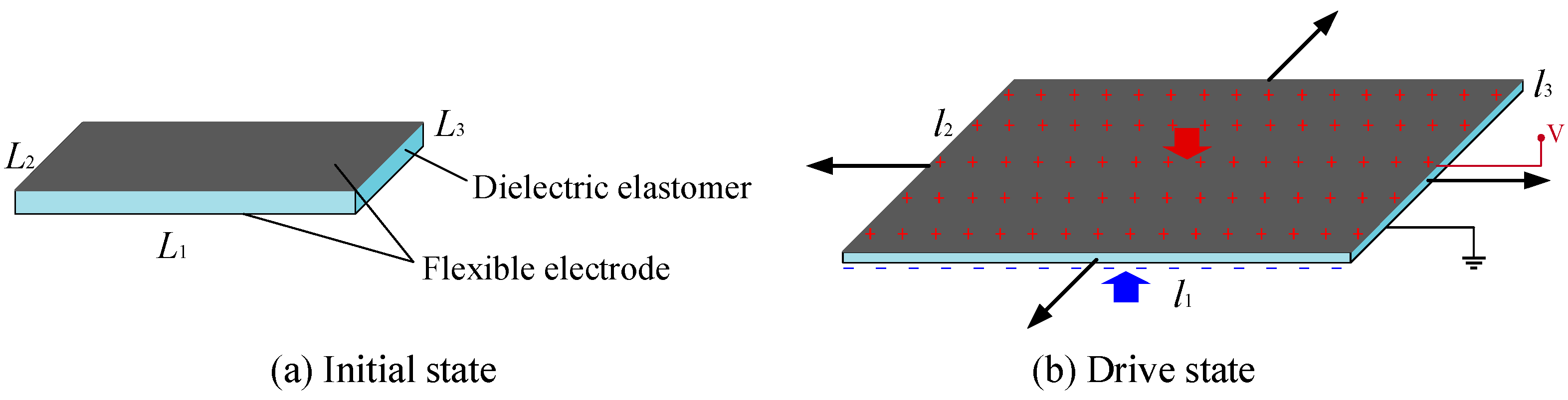
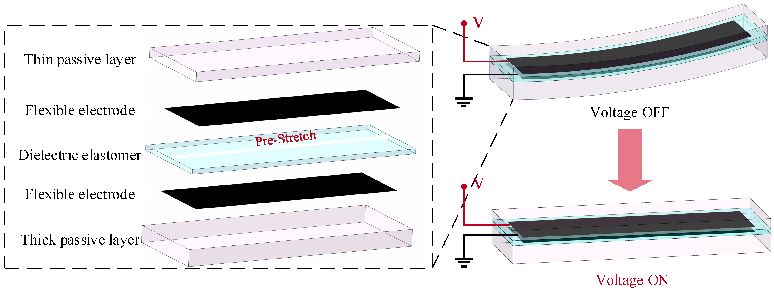
2.1. Actuator Principle and Structure Design
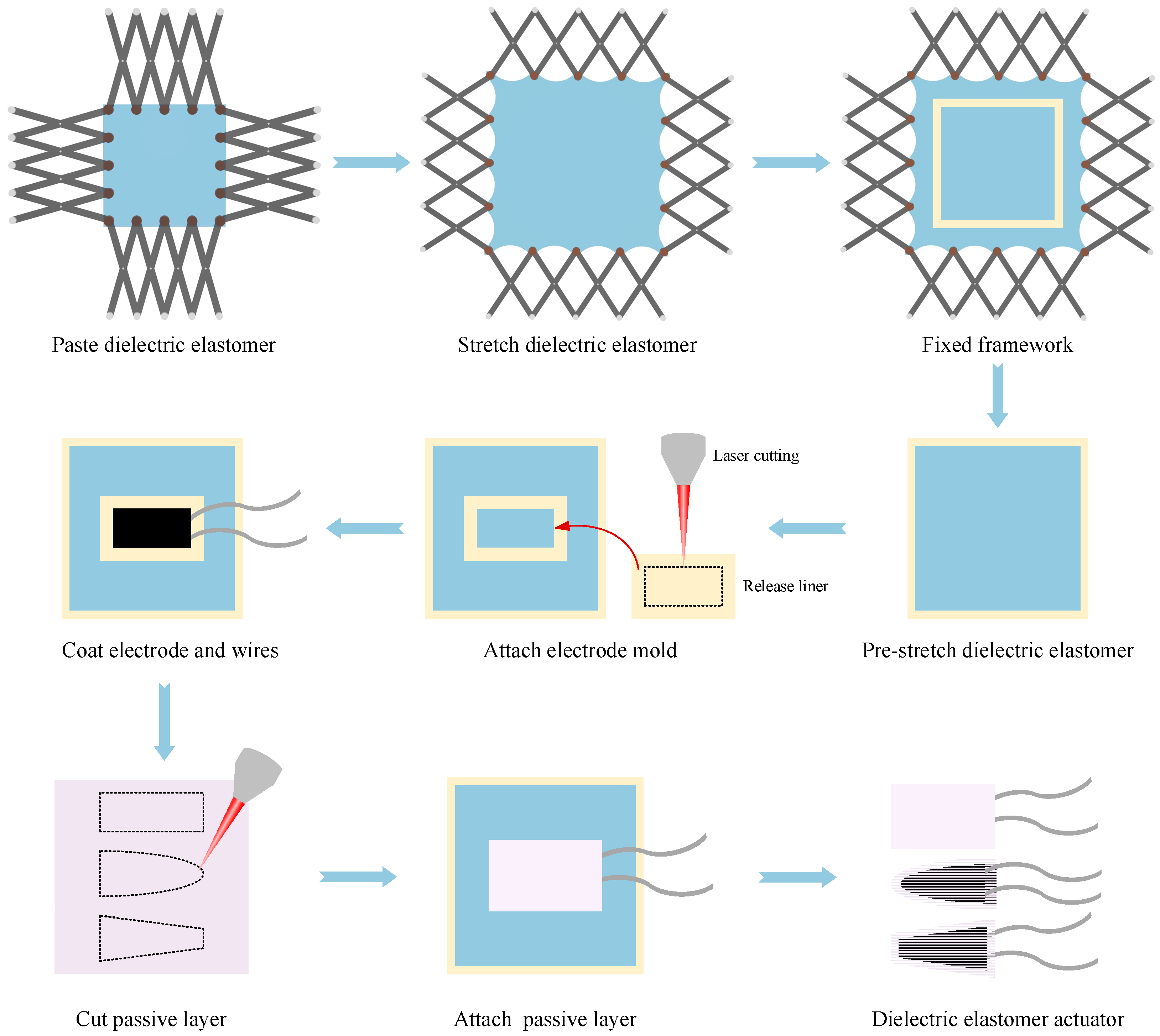
2.2. Preparation of DEA
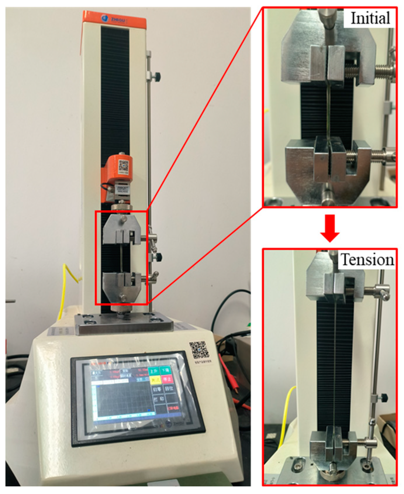
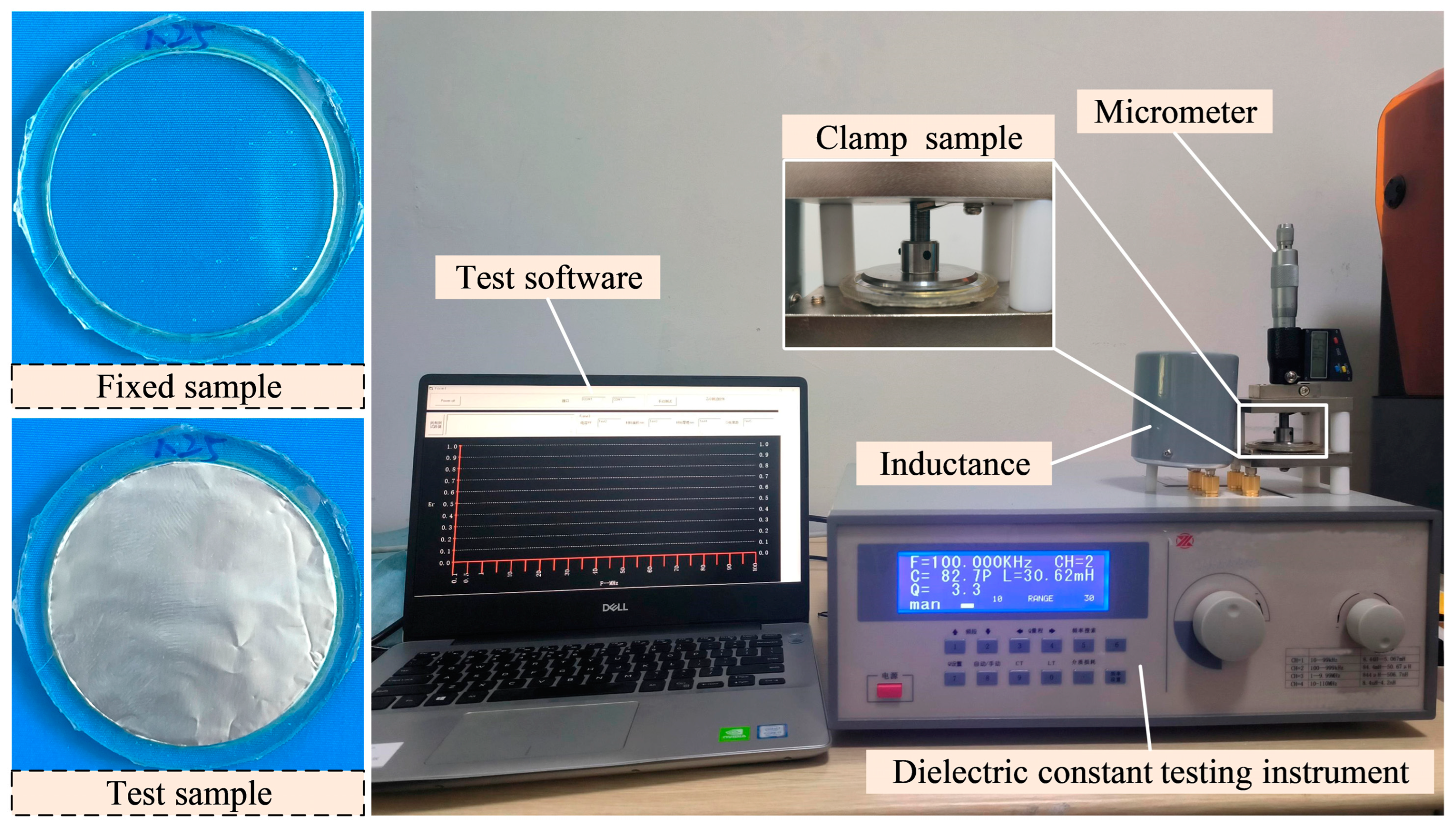
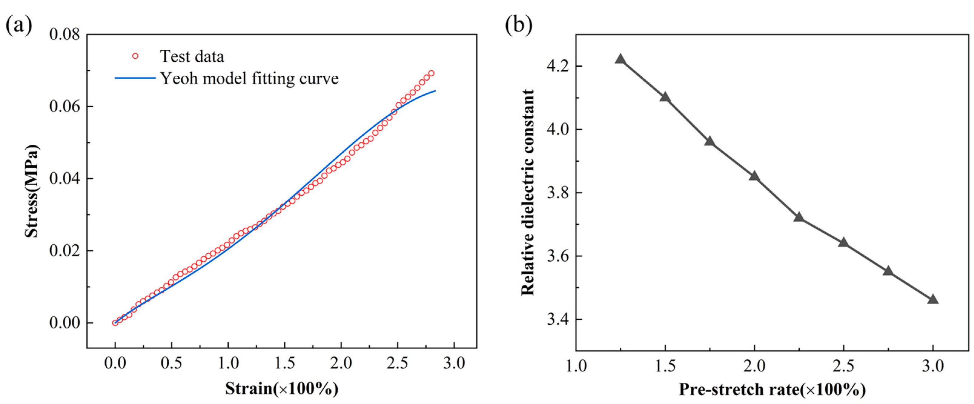
2.3. Performance Testing of DE
2.4. Characterizations
3. Result and Discussion
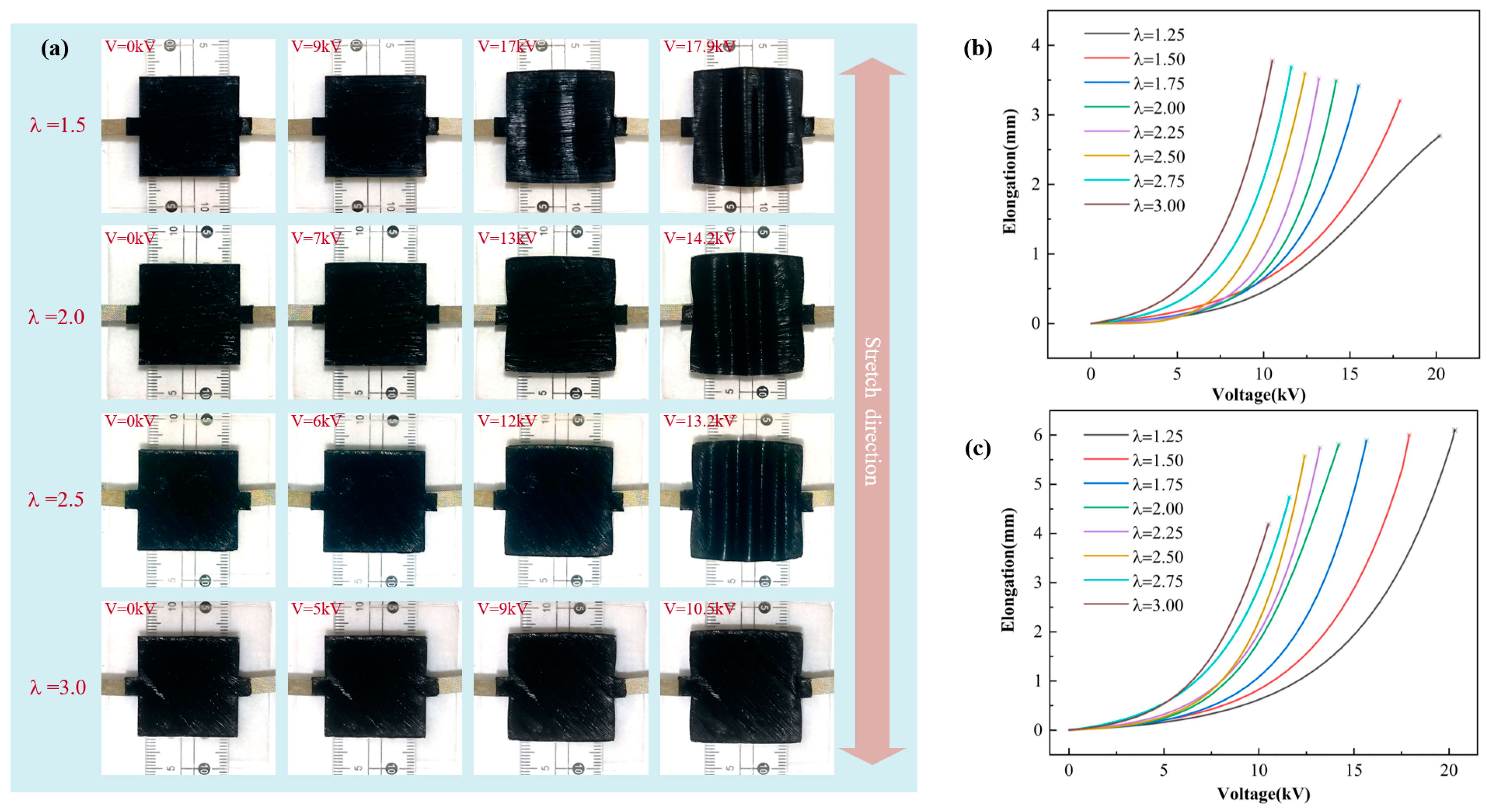
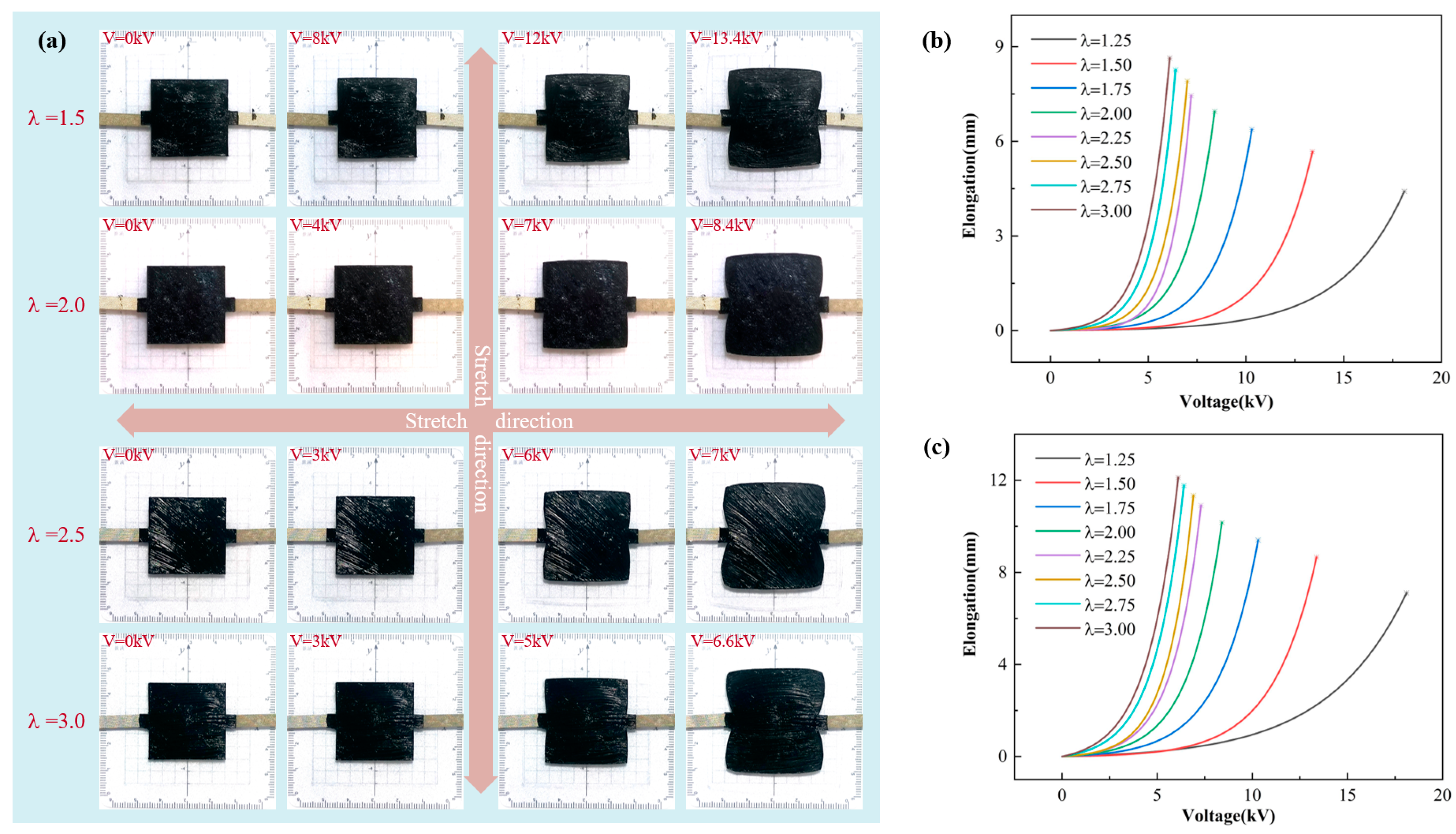
3.1. The Relationship Between Pre-Stretch Ratio and DEA Deformation Degree
3.2. Shape Design of DEA
3.3. Performance Test of DEA
3.4. Grasp Test of the Designed Flexible Gripper
4. Conclusions
- (1)
- Under uniaxial stretching, the deformation of the DEA in the stretching direction gradually increases and decreases in the unstretched direction with the increase in the pre-stretch ratio. Under biaxial stretching, DEA deformation increases with the increase in the pre-stretch ratio.
- (2)
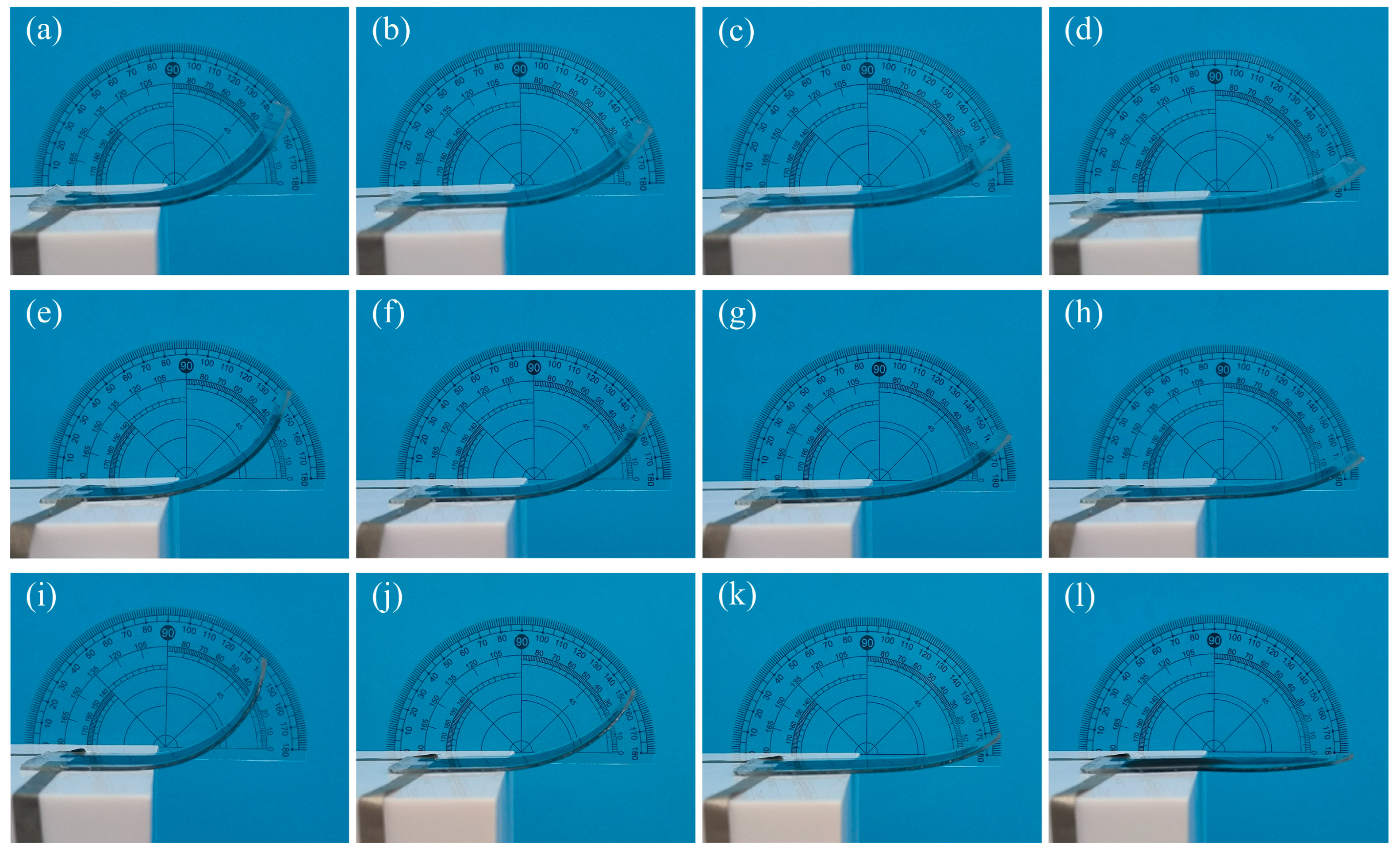
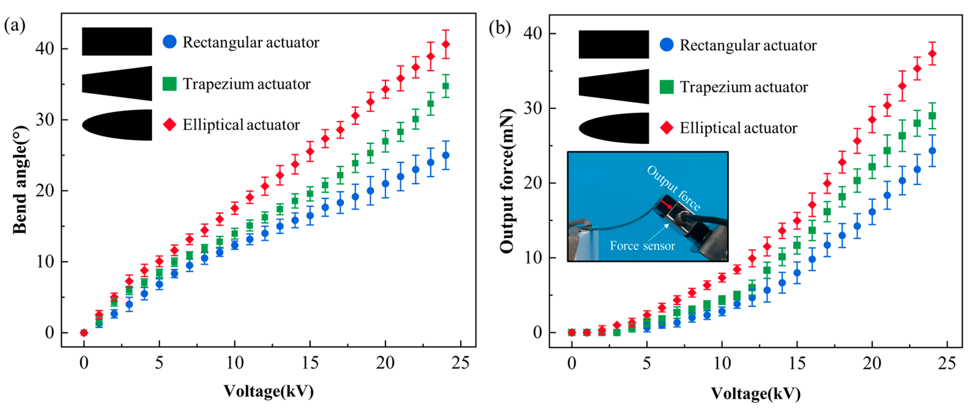
- The shape of the DEA has a certain influence on the bending deformation range under the same conditions, and the elliptical DEA has a larger bending deformation range and higher output force compared with the rectangular DEA and the trapezium DEA.
- (3)
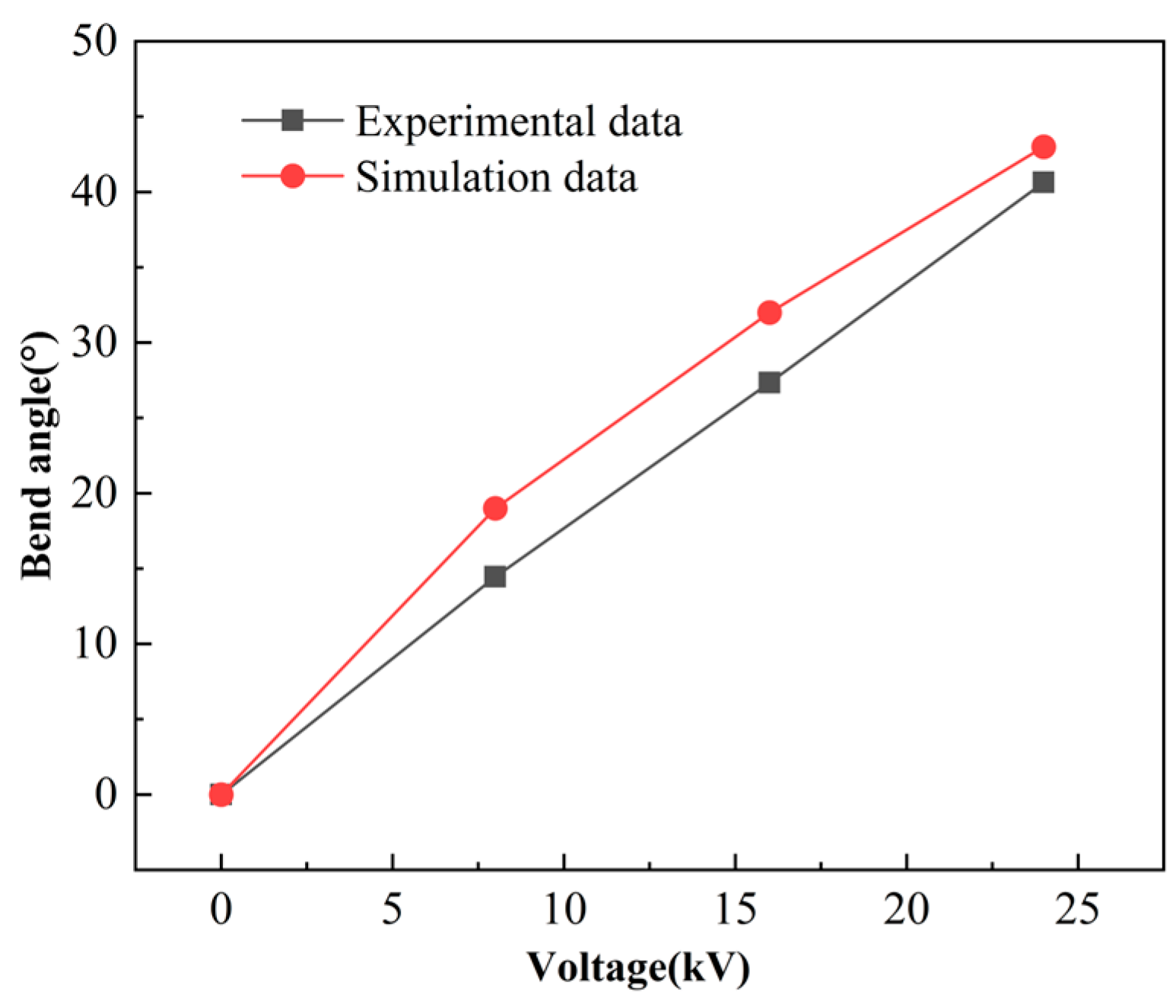
- The bending angle curve and output force curve after applying voltage to the elliptical DEA show that the elliptical DEA can produce a maximum bending deformation of 40° and an output force of 37.2 mN at a voltage of 24 kV.
- (4)
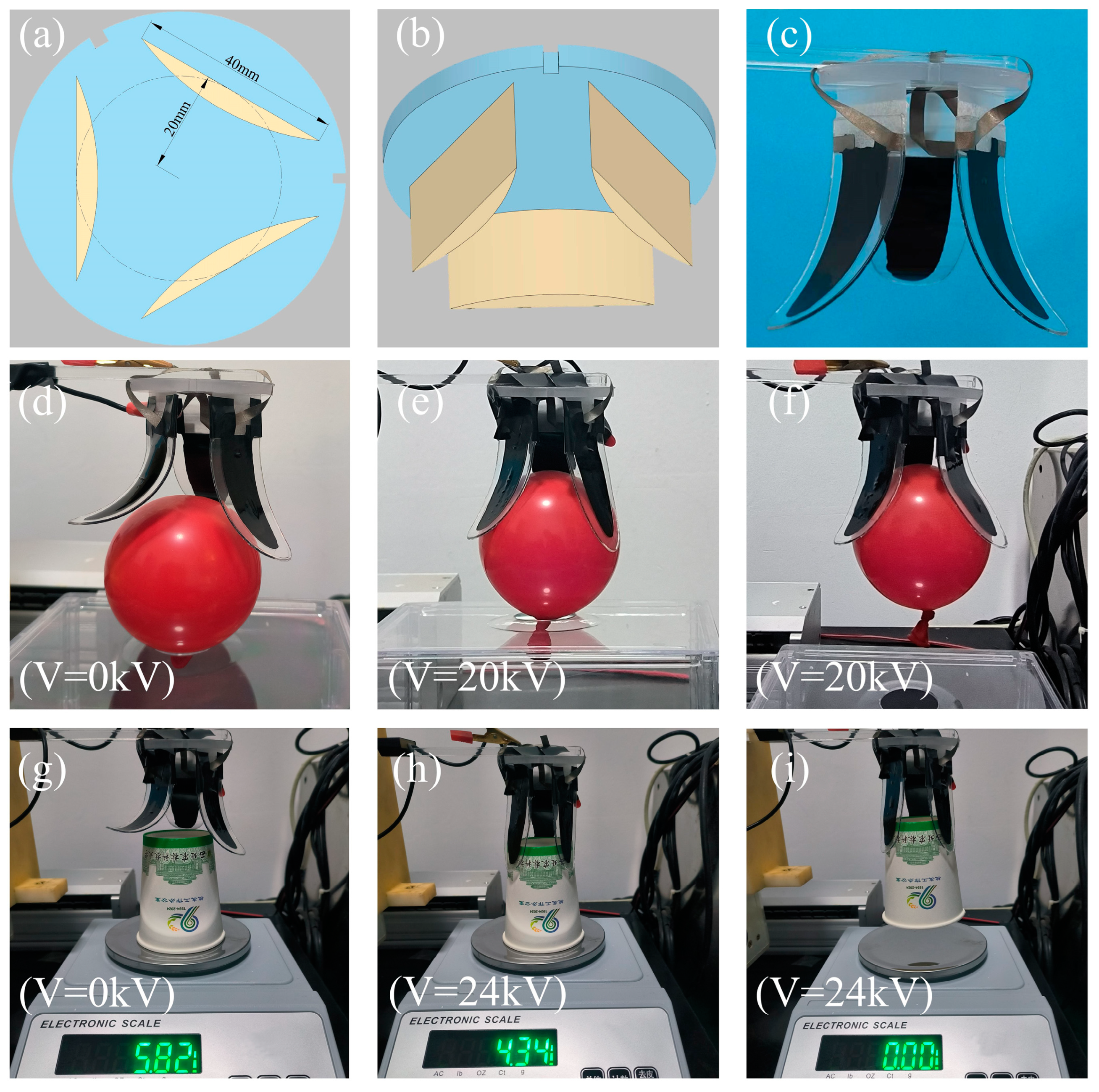
- Looking ahead, flexible sensors with high sensitivity and a wide linear range will be arrayed and integrated into the flexible gripper proposed in this research. This integration is expected to show great application scenarios in the fields of smart agriculture, human–computer interaction, and soft robots.
Author Contributions
Funding
Data Availability Statement
Acknowledgments
Conflicts of Interest
References
- Rus, D.; Tolley, M.T. Design, fabrication and control of soft robots. Nature 2015, 521, 467–475. [Google Scholar] [CrossRef] [PubMed]
- Park, J.; Lee, Y.; Cho, S.; Choe, A.; Yeom, J.; Ro, Y.G.; Ko, H. Soft Sensors and Actuators for Wearable Human–Machine Interfaces. Chem. Rev. 2024, 124, 1464–1534. [Google Scholar] [CrossRef] [PubMed]
- Chen, Y.; Gao, Z.; Zhang, F.; Wen, Z.; Sun, X. Recent progress in self-powered multifunctional e-skin for advanced applications. Exploration 2022, 2, 20210112. [Google Scholar] [CrossRef] [PubMed]
- Qi, Z.; Sun, X.; Xu, J. A Kirigami Multi-Stable Flexible Gripper with Energy-Free Configurations Switching. Adv. Intell. Syst. Ger. 2024, 6, 2400038. [Google Scholar] [CrossRef]
- Sut, D.J.; Sethuramalingam, P. Soft manipulator for soft robotic applications: A review. J. Intell. Robot. Syst. 2023, 108, 10. [Google Scholar] [CrossRef]
- Wang, H.; Gao, B.; Hu, A.; He, J. A variable stiffness gripper with reconfigurable finger joint for versatile manipulations. Soft. Robot. 2023, 10, 1041–1054. [Google Scholar] [CrossRef] [PubMed]
- Zhu, Z.; Liu, Y.; Ju, J.; Lu, E. Design and Experimental Test of Rope-Driven Force Sensing Flexible Gripper. Sensors 2024, 24, 6407. [Google Scholar] [CrossRef] [PubMed]
- Wang, Y.; Liang, X. Soft Pumps: Catalysts for Advancing Fluid-Driven Soft Robots. Adv. Eng. Mater. 2024, 26, 2400123. [Google Scholar] [CrossRef]
- Du, X.; Cui, H.; Xu, T.; Huang, C.; Wang, Y.; Zhao, Q.; Wu, X. Reconfiguration, camouflage, and color-shifting for bioinspired adaptive hydrogel-based millirobots. Adv. Funct. Mater. 2020, 30, 1909202. [Google Scholar] [CrossRef]
- Pang, H.; Xie, J.; Meng, X.; Sun, R.; Chen, J.; Guo, C.; Zhou, T. Portable organophosphorus pesticide detection device based on controllable microfluidic and luminol composite nanofibers. J. Food. Eng. 2024, 364, 111810. [Google Scholar] [CrossRef]
- Lu, H.; Zhang, M.; Yang, Y.; Huang, Q.; Fukuda, T.; Wang, Z.; Shen, Y. A bioinspired multilegged soft millirobot that functions in both dry and wet conditions. Nat. Commun. 2018, 9, 3944. [Google Scholar] [CrossRef] [PubMed]
- Zhang, C.L.; Lai, Z.H.; Rao, X.X.; Zhang, J.W.; Yurchenko, D. Energy harvesting from a novel contact-type dielectric elastomer generator. Energ. Convers. Manag. 2020, 205, 112351. [Google Scholar] [CrossRef]
- Gupta, U.; Qin, L.; Wang, Y.; Godaba, H.; Zhu, J. Soft robots based on dielectric elastomer actuators: A review. Smart. Mater. Struct. 2019, 28, 103002. [Google Scholar] [CrossRef]
- Liang, W.; Wu, W.; Chen, W.; Ren, L.; Wang, K.; Qian, Z.; Ren, L. A bioinspired robotic knee with controlled joint surfaces and adjustable ligaments. Bioinspir. Biomim. 2022, 17, 066006. [Google Scholar] [CrossRef] [PubMed]
- Guo, Y.; Guo, J.; Liu, L.; Liu, Y.; Leng, J. Bioinspired multimodal soft robot driven by a single dielectric elastomer actuator and two flexible electroadhesive feet. Extreme. Mech. Lett. 2022, 53, 101720. [Google Scholar] [CrossRef]
- Annapooranan, R.; Wang, Y.; Cai, S. Harnessing soft elasticity of liquid crystal elastomers to achieve low voltage driven actuation. Adv. Mater. Technol. Us. 2023, 8, 2201969. [Google Scholar] [CrossRef]
- Sun, W.; Zhao, B.; Zhang, F. Design analysis and actuation performance of a push-pull dielectric elastomer actuator. Polymers 2023, 15, 1037. [Google Scholar] [CrossRef] [PubMed]
- Zhang, E.; Pang, T.; Zhang, Y.; Huang, F.; Gong, M.; Lin, X.; Zhang, L. Fully 3D printed dielectric elastomer actuators based on silicone and its composites. Polym. Compos. 2024, 45, 12159. [Google Scholar] [CrossRef]
- Sun, W.; Liang, H.; Zhang, F.; Wang, H.; Lu, Y.; Li, B.; Chen, G. Dielectric elastomer minimum energy structure with a unidirectional actuation for a soft crawling robot: Design, modeling, and kinematic study. Int. J. Mech. Sci. 2023, 238, 107837. [Google Scholar] [CrossRef]
- Cai, Y.; Chen, Z.; Luo, Y. Confining Nano-ZrO2 in Nanodomains Leads to Electroactive Artificial Muscle with Large Deformation. Biomacromolecules 2024, 25, 5019. [Google Scholar] [CrossRef] [PubMed]
- Kuroki, T.; Narita, M.; Kageyama, T.; Yamasaki, H.; Matsumoto, T.; Ida, T.; Okubo, M. Higher Adhesion Strength Over 10 N/mm Between Rubber and Fluoropolymer Film When Treated by Atmospheric Plasma-Graft Polymerization. IEEE. T. Ind. Appl. 2022, 59, 450. [Google Scholar] [CrossRef]
- Li, F.; Wang, L.; Gao, L.; Zu, D.; Zhang, D.; Xu, T.; Hu, B.L. Reducing Dielectric Loss of High-Dielectric-Constant Elastomer via Rigid Short-Chain Crosslinking. Adv. Mater. 2024, 36, 2411082. [Google Scholar] [CrossRef] [PubMed]
- Zhang, H.; Zhu, J.; Wen, H.; Xia, Z.; Zhang, Z. Biomimetic human eyes in adaptive lenses with conductive gels. J. Mech. Behav. Biomed. 2023, 139, 105689. [Google Scholar] [CrossRef] [PubMed]
- He, X.; Xie, J.; Pang, H.; Sun, R.; Zhou, T.; Fan, H.; Zhou, Z. Research on multiwalled carbon nanotubes spray method for preparing flexible piezoresistive tactile sensor. J. Appl. Polym. Sci. 2024, 141, e55576. [Google Scholar] [CrossRef]
- Pelrine, R.E.; Kornbluh, R.D.; Joseph, J.P. Electrostriction of polymer dielectrics with compliant electrodes as a means of actuation. Sensor. Actuat. A Phys. 1998, 64, 77. [Google Scholar] [CrossRef]
- Pelrine, R.; Kornbluh, R.; Joseph, J.; Heydt, R.; Pei, Q.; Chiba, S. High-field deformation of elastomeric dielectrics for actuators. Mat. Sci. Eng. C Mater. 2000, 11, 89. [Google Scholar] [CrossRef]
- Qiu, Y.; Zhang, E.; Plamthottam, R.; Pei, Q. Dielectric elastomer artificial muscle: Materials innovations and device explorations. Accounts. Chem. Res. 2019, 52, 316. [Google Scholar] [CrossRef]
- Niu, S.; Wang, Z. Experimental analysis of the characteristics of an acrylic elastomer. Mater. Res. Innov. 2015, 19, S8–S17. [Google Scholar] [CrossRef]
- Kofod, G.; Wirges, W.; Paajanen, M.; Bauer, S. Energy minimization for self-organized structure formation and actuation. Appl. Phys. Lett. 2007, 90, 081916. [Google Scholar] [CrossRef]
- Araromi, O.A.; Gavrilovich, I.; Shintake, J.; Rosset, S.; Richard, M.; Gass, V.; Shea, H.R. Rollable multisegment dielectric elastomer minimum energy structures for a deployable microsatellite gripper. IEEE ASME Trans. Mechatron. 2014, 20, 438. [Google Scholar] [CrossRef]
- Shintake, J.; Rosset, S.; Schubert, B.; Mintchev, S.; Floreano, D.; Shea, H. DEA for soft robotics: 1-gram actuator picks up a 60-gram egg. In Proceedings of the SPIE’s Smart Structures and Materials + Nondestructive Evaluation and Health Monitoring, San Diego, CA, USA, 1 April 2015; p. 94301S. [Google Scholar] [CrossRef]
- Su, S.; He, T.; Yang, H. 3D printed multilayer dielectric elastomer actuators. Smart. Mater. Struct. 2023, 32, 035021. [Google Scholar] [CrossRef]
- Shintake, J.; Rosset, S.; Schubert, B.E.; Floreano, D.; Shea, H. Versatile soft grippers with intrinsic electroadhesion based on multifunctional polymer actuators. Adv. Mater. 2016, 28, 231. [Google Scholar] [CrossRef] [PubMed]
- Weng, M.; Zhou, J.; Zhou, P.; Shang, R.; You, M.; Shen, G.; Chen, H. Multi-Functional Actuators Made with Biomass-Based Graphene-Polymer Films for Intelligent Gesture Recognition and Multi-Mode Self-Powered Sensing. Adv. Sci. 2024, 11, 2309846. [Google Scholar] [CrossRef]
- Zhou, J.; Chen, H.; Wu, Z.; Zhou, P.; You, M.; Zheng, C.; Weng, M. 2D Ti3C2Tx MXene-based light-driven actuator with integrated structure for self-powered multi-modal intelligent perception assisted by neural network. Nano Energy 2025, 134, 110552. [Google Scholar] [CrossRef]
- Pelrine, R.; Kornbluh, R.; Pei, Q.; Joseph, J. High-speed electrically actuated elastomers with strain greater than 100%. Science 2000, 287, 836. [Google Scholar] [CrossRef] [PubMed]
- Iannarelli, A.; Niasar, M.G.; Ross, R. The effects of static pre-stretching on the short and long-term reliability of dielectric elastomer actuators. Smart Mater. Struct. 2019, 28, 125014. [Google Scholar] [CrossRef]
- Ji, X.; Liu, X.; Cacucciolo, V.; Imboden, M.; Civet, Y.; El Haitami, A.; Shea, H. An autonomous untethered fast soft robotic insect driven by low-voltage dielectric elastomer actuators. Sci. Robot. 2019, 4, eaaz6451. [Google Scholar] [CrossRef]
- Jahren, S.E.; Martinez, T.; Walter, A.; Clavica, F.; Heinisch, P.P.; Buffle, E.; Perriard, Y. Novel para-aortic cardiac assistance using a pre-stretched dielectric elastomer actuator. Interdiscip. Cardiovasc. Thorac. Surg. 2024, 38, ivae027. [Google Scholar] [CrossRef]
- Guo, Y.; Liu, L.; Liu, Y.; Leng, J. Review of dielectric elastomer actuators and their applications in soft robots. Adv. Intell. Syst. 2021, 3, 2000282. [Google Scholar] [CrossRef]
- An, L.; Wang, F.; Cheng, S.; Lu, T.; Wang, T.J. Experimental investigation of the electromechanical phase transition in a dielectric elastomer tube. Smart Mater. Struct. 2015, 24, 035006. [Google Scholar] [CrossRef]
- Godaba, H.; Foo, C.C.; Zhang, Z.Q.; Khoo, B.C.; Zhu, J. Giant voltage-induced deformation of a dielectric elastomer under a constant pressure. Appl. Phys. Lett. 2014, 105, 112901. [Google Scholar] [CrossRef]
- Zhao, X.; Suo, Z. Electrostriction in elastic dielectrics undergoing large deformation. J. Appl. Phys. 2008, 104, 123530. [Google Scholar] [CrossRef]
- ASTM D412−15a; Standard Test Methods for Vulcanized Rubber and Thermoplastic Elastomers—Tension. ASTM International: West Conshohocken, PA, USA, 2015.
- Sun, R.; Xie, J.; Meng, X.; Pang, H.; Gong, C.; Zhou, F. Polydimethylsiloxane/carboxylated h ydroxylated multiwalled carbon nanotubes/polyimide composite membrane wearable flexible piezoresistive tactile sensor device with microsphere array. J. Appl. Polym. Sci. 2022, 139, e52964. [Google Scholar] [CrossRef]


Disclaimer/Publisher’s Note: The statements, opinions and data contained in all publications are solely those of the individual author(s) and contributor(s) and not of MDPI and/or the editor(s). MDPI and/or the editor(s) disclaim responsibility for any injury to people or property resulting from any ideas, methods, instructions or products referred to in the content. |
© 2025 by the authors. Licensee MDPI, Basel, Switzerland. This article is an open access article distributed under the terms and conditions of the Creative Commons Attribution (CC BY) license (https://creativecommons.org/licenses/by/4.0/).
Share and Cite
Meng, X.; Xie, J.; Pang, H.; Wei, W.; Niu, J.; Zhu, M.; Gu, F.; Fan, X.; Fan, H. Design of Dielectric Elastomer Actuator and Its Application in Flexible Gripper. Micromachines 2025, 16, 107. https://doi.org/10.3390/mi16010107
Meng X, Xie J, Pang H, Wei W, Niu J, Zhu M, Gu F, Fan X, Fan H. Design of Dielectric Elastomer Actuator and Its Application in Flexible Gripper. Micromachines. 2025; 16(1):107. https://doi.org/10.3390/mi16010107
Chicago/Turabian StyleMeng, Xiaoyu, Jiaqing Xie, Haoran Pang, Wenchao Wei, Jiping Niu, Mingqiang Zhu, Fang Gu, Xiaohuan Fan, and Haiyan Fan. 2025. "Design of Dielectric Elastomer Actuator and Its Application in Flexible Gripper" Micromachines 16, no. 1: 107. https://doi.org/10.3390/mi16010107
APA StyleMeng, X., Xie, J., Pang, H., Wei, W., Niu, J., Zhu, M., Gu, F., Fan, X., & Fan, H. (2025). Design of Dielectric Elastomer Actuator and Its Application in Flexible Gripper. Micromachines, 16(1), 107. https://doi.org/10.3390/mi16010107