Article

A Wide-Band Antenna with Circular Polarization Utilizing a U-Shaped Radiator and Parasitic Strip for Wireless Communications

1
Communications Department, Delta Higher Institute for Engineering and Technology, Mansoura 35681, Egypt
2
Microstrip Department, Electronics Research Institute, New Nozha, Cairo 11843, Egypt
3
Electrical Engineering Department, College of Engineering, Jouf University, Sakaka 72388, Al Jouf, Saudi Arabia
4
Department of Electronics and Communication Engineering Centre for IoT and AI (CITI), KPR Institute of Engineering and Technology, Coimbatore 641407, India
5
Electronics and Communications Engineering Department, Faculty of Engineering, Minia University, Minia 61519, Egypt
*
Author to whom correspondence should be addressed.
Micromachines 2023, 14(7), 1308; https://doi.org/10.3390/mi14071308
Submission received: 1 June 2023 / Revised: 19 June 2023 / Accepted: 23 June 2023 / Published: 26 June 2023

Abstract

:
A circularly polarized (CP) and wide-band monopole antenna with a miniaturized size is suggested in this study. The suggested structure is composed of a U-shaped radiator on the front side, a partial ground plane with two rectangle slots, and a quadrilateral-shaped parasitic strip on the back side of the FR4 substrate. A wide-band operation with S11 ≤ −10 dB was achieved by regulating the radiator and the partial ground that was placed on the second side of the antenna substrate. The CP was achieved when excited two modes with the same amplitude and a 90° phase difference. This could be generated by regulating the slots’ dimensions in the ground plane. Moreover, a quadrilateral-shaped parasitic strip placed on the second side with the partial ground was utilized to extend the 3 dB axial ratio (AR) bandwidth. The suggested structure is simulated, prototyped, and measured to confirm the desired requirements with a total size of 30 × 32 mm2 (0.4 × 0.42 λ0 at 4 GHz). The tested outcomes have a bandwidth of S11 ≤ −10 dB (81.25%) (5.2 GHz, 3.8–9 GHz) and a 3 dB axial ratio (AR) bandwidth (30.7%) (1.63 GHz, 4.48–6.11 GHz). The antenna’s different parameters are discussed, which recommend the suggested antenna to be used in UWB, sub 6 GHz, and WLAN wireless applications.

1. Introduction

Recently, wireless communication systems of a small and compact size that operate in a wide-band operation need compact and wide-band antennas that can be easily integrated with them [1,2]. CP antennas have several benefits, such as better mobility, orientation flexibility between the transmitting and receiving ends, decreasing multipath interference, and polarization mismatch [3,4,5]. Two orthogonal modes with equal magnitudes and a 90° phase shift must be generated to produce the CP operation [1].
In modern wireless systems, for example, wide-band circular polarization (CP) antennas, radio frequency identification (RFID), and global positioning systems (GPSs) are recommended and utilized. Recently, wireless systems have been operated at different frequency bands. Therefore, wide-band CP antennas are considered a good choice to reduce the system’s complexity and price [6,7,8]. Microstrip [9,10,11,12], dielectric resonator (DRAs) [7,8], slot [13,14], and monopole antennas [2,3,4,5,15,16,17,18,19,20,21,22,23,24] are used to achieve CP behavior.
Microstrip antennas have several advantages, such as low price, simple design, small size, ease of integration, and simplicity in CP realization. Therefore, the microstrip antenna is used in several communication systems. However, conventional CP antennas are produced with a small 3 dB axial ratio with a large size, which cannot be suitable for wide-band systems [9,10]. For this reason, monopole antennas can be used to produce a wide-band CP operation. The monopole antennas can be fabricated easily and have a small size, low price, stable radiation patterns, wideband bandwidth, and CP operation. Therefore, recently, researchers have extensively studied them [2,4,5]. To enhance the 3 dB AR bandwidth and preserve the antenna compactness, a monopole antenna can be utilized [2,3,4,5,15,16,17,18,19,20,21,22,23,24].
In [2], a parasitic G-shaped strip is added to a C-shaped monopole antenna to generate a CP operation. The antenna is operated from 3.92 to 7.52 GHz (62.9%). The FR4 substrate at 1.6 mm is utilized in the design. The antenna had a size of 30 × 32 mm2 and peak gain of 3.6 dB. Additionally, the ground plane is modified to increase the 3 dB AR bandwidth to 53.92% from 4.28 to 7.44 GHz. The antenna has a simple structure with a wide-band 3 dB AR bandwidth and is utilized for WLAN communication.
The UWB CP operation generated using a sequential phase feed is investigated in [3]. It is composed of a monopole antenna with a circular arc-shaped radiator on the top of the RO4003 substrate with a 0.813 mm thickness and a quasi-elliptical strip connected to the partial ground on the other side. The antenna is operated from 1.8 to 7.3 GHz (120.9%). The antenna has a size of 120 × 120 mm2 and a peak gain of 11.2 dB. Additionally, the antenna has a 3 dB AR bandwidth from 1.5 to 7.5 GHz (133.33%). While the AR in [3] has a UWB operation, the antenna has a larger size and complex design.
In [4], a broadband antenna with a C-shaped monopole patch on the top side and an open-loop rectangular resonator and modified ground on the back side is investigated to extend the 3 dB AR to 65.2% from 4.28 to 8.42 GHz. A compact broadband antenna with a circular C-shaped patch, an improved ground plane, and a large size to extend the 3 dB AR are investigated in [5]. The antenna is operated from 2.25 to 7.35 GHz (106.3%). The FR4 substrate of 1.6 mm is utilized in the design. The antenna has a size of 49 × 55 mm2 and a peak gain of 6.55 dB. Additionally, the ground plane is modified to increase the 3 dB AR bandwidth to 104.7% from 2.05 to 6.55 GHz. The antenna has a simple structure with a wide-band 3 dB AR bandwidth and is utilized for WLAN communication; however, it has a large size.
A microstrip antenna utilizing a fractal-defected ground structure is discussed in [9]. The antenna is worked from 1.55 to 1.58 GHz (1.9%). A substrate of a dielectric constant of 10 and 3.88 mm thicknesses is utilized in the design. The antenna has a size of 45 × 45 mm2 and a peak gain of 2.2 dB. The antenna has a simple structure with a narrow 3 dB AR from 1.572 to 1.578 GHz (0.4%). The antenna has a narrow band of 3 dB AR bandwidth with a large size. A 3D with complex structure microstrip antenna is introduced in [10]. An L-shaped slot is etched in the patch. The antenna is operated around 1.9 (27.2%). A substrate of a dielectric constant of 2.7 and 9 mm thicknesses is utilized in the design. The antenna has a size of 80 × 80 mm2 and a peak gain of 4.3 dB. The antenna has a 3 dB AR bandwidth of 3%. The antenna has a complex structure with a large size.
In [12], a microstrip antenna with an H-shaped and reactive impedance surface (RIS) is investigated. The antenna is operated from 4.64 to 7.3 GHz (44.5%). The RO4003 substrate with 5.88 mm is utilized in the design. The antenna has a size of 32 × 32 mm2. The antenna has a peak gain of 7.2 dB. Additionally, the antenna has a 3 dB AR bandwidth of 27.5% from 4.55 to 6 GHz. The antenna has a complex structure and it is utilized for WLAN communication. A slot antenna with a CPW feed is introduced in [13]. The antenna is operated from 1.78 to 5.64 GHz (104%). The 1.66 mm FR4 substrate is utilized in the design. The antenna has a size of 54 × 54 mm2 and a peak gain of 3.8 dB. Additionally, the antenna has a 3 dB AR bandwidth of 58.6% from 2.85 to 5.21 GHz. The antenna has a simple structure with a large size and it is utilized for WLAN communication.
Moreover, some modifications are utilized in the monopole antenna to increase the 3 dB AR bandwidth. Lumped capacitors are used in [15]. An inverted U-shaped monopole antenna attached to lumped capacitors is used to generate the CP operation. The antenna is operated from 3.75 to 7 GHz (60.5%). A substrate of a dielectric constant of 2.2 and 1.52 mm thicknesses is utilized in the design. The antenna has a size of 52 × 55 mm2 and a peak gain of 4.8 dB. Additionally, it has a 3 dB AR bandwidth of 4% from 4.25 to 5.95 GHz. The antenna has a simple structure with a large size and works for wireless communication. Parasitic strips are investigated in [16,18]. A Y-shaped monopole antenna is suggested in [19]. The antenna is operated from 2.25 to 2.35 GHz (28.6%). A substrate of a dielectric constant of 2.2 and 3.1 mm thicknesses is utilized in the design. The antenna has a size of 50 × 55 mm2 and a peak gain of 2.9 dB. Additionally, it has a 3 dB AR bandwidth of 4% from 2.25 to 2.35 GHz. The antenna has a simple structure with a large size and works for satellite communication.
A slot antenna with an L-shape is suggested in [22]. An L-shaped monopole slot antenna with a C-shaped feed is utilized to generate the CP operation. The antenna is operated from 1.48 to 1.93 GHz (30%). The 0.8 mm FR4 substrate is utilized in the design. The antenna has a size of 70 × 70 mm2 and a peak gain of 2.45 dB. Additionally, it has a 3 dB AR bandwidth of 32% from 1.42 to 1.97 GHz. The antenna has a simple structure with a large size and works for satellite communication. A parasitic open-loop resonator is added to a rectangular monopole antenna to generate the CP operation. The antenna is operated from 1.48 to 4.24 GHz (96.5%). The 1 mm FR4 substrate is utilized in the design. The antenna has a size of 50 × 55 mm2 and a peak gain of 3.5 dB. Additionally, the ground plane is modified to increase the 3 dB AR bandwidth to 63.3% from 2.05 to 3.95 GHz. The antenna has a simple structure with a wideband 3 dB AR bandwidth and a large size.
A wide-band CP antenna is introduced in this work. A U-shaped radiator on the front side, a partial ground plane with two rectangle slots, and a quadrilateral-shaped parasitic strip on the back side are utilized to produce the CP feature. The CP is achieved when we excited two modes with the same amplitude and a 90° phase difference. This can be generated by regulating the slot’s dimensions and adding a quadrilateral-shaped parasitic strip to the ground plane. The tested outcomes have a bandwidth of S11 ≤ −10 dB (81.25%) (5.2 GHz, 3.8–9 GHz) and a 3 dB axial ratio (AR) bandwidth (30.7%) (1.63 GHz, 4.48–6.11 GHz). The designed antenna keeps the same features as a common turnstile antenna, such as simplicity, low cost, compact, low profile, and broadband CP antenna. All simulated results are extracted utilizing CST software. The suggested antenna can be used in UWB, sub 6 GHz, and WLAN wireless applications.
The paper is organized as follows: (I) The literature review is introduced. (II) The configuration of the antenna is investigated. (III) The simulation and measurement outcomes are provided. (IV) The conclusion is presented.

2. Proposed Antenna Structure

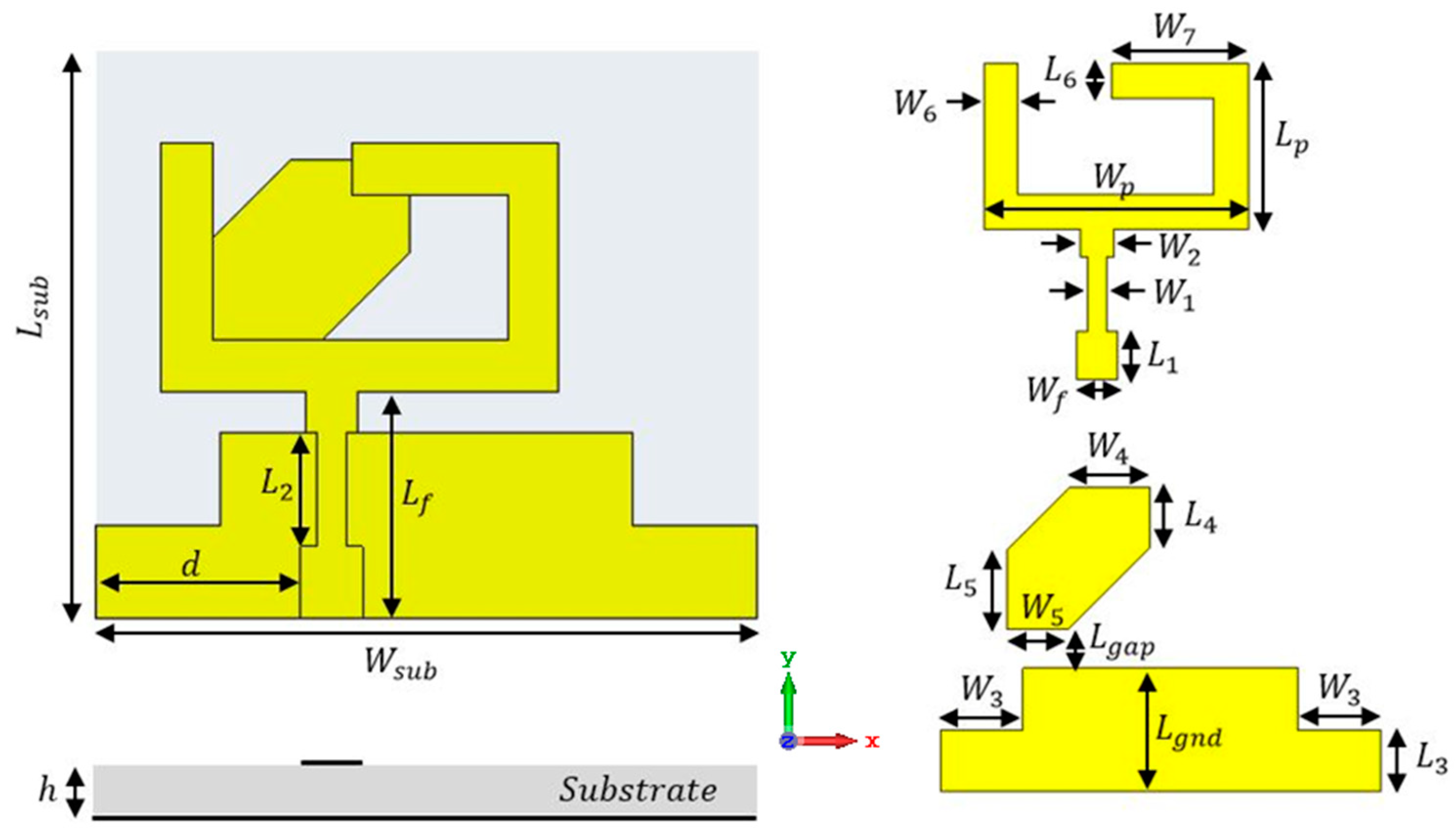
2.1. Antenna Design and Configuration

The proposed wide-band CP monopole antenna with the complete geometrical configuration is shown in Figure 1. FR4 with a total size of 32 × 30 × 1.6 mm3 and εr = 4.4, tan δ = 0.025 was used as a substrate. The suggested antenna was connected to a 50 Ω microstrip feed line with an optimal position to enhance the matching of the antenna. An L-shaped connected to a C-shaped mirror to compose a suggested U-shaped radiator was added to the front side. Moreover, a partial ground plane with two rectangle slots and a quadrilateral-shaped parasitic strip was added to the back side of the substrate. The two rectangle slots were cut from the edge of the ground plane to achieve CP modes at high frequencies. The wide CP generation was achieved by adding a quadrilateral strip to the bottom of the substrate, as illustrated in Figure 1. It was used to create a CP mode at a lower frequency that, in turn, improved the AR over the desired frequency. Table 1 presents the dimensions of the antenna.
The suggested structure was passed through four stages to achieve the desired final design. The four-step antenna design procedure is illustrated in Figure 2. In Ant. #1, an L-shaped radiator on the front side with the partial ground on the bottom was designed, as shown in Figure 2. As displayed in Figure 3 (the green curve), the antenna is operated at dual-wide-band ranges. The first started from 3.5 to 5.9 GHz and the second worked from 6.5 up to 10 GHz. To extend the impedance bandwidth to cover the two ranges from 4 up to 9 GHz, as shown in Figure 3 (the red curve), the mirror of a C-shaped radiator was connected to an L-shape to achieve the U-shaped radiator, as shown in Figure 2 (Ant. #2). From the two steps, the desired wide-band operating bandwidth can be achieved; however, the CP behavior is not generated, which is related to AR, as shown in Figure 4. Therefore, to achieve the CP feature, a rectangular part was cut from the two edges of the ground plane as Ant. #3 was introduced to improve the antenna matching, as shown in Figure 2 and Figure 3 (blue curve). Moreover, a CP mode was excited at 5.5 GHz, as shown in Figure 4. The 3 dB AR was operated from 5.2 to 6 GHz.
The CP radiation can be obtained by achieving two orthogonal modes with equal amplitudes and a 90° phase difference. However, the conventional monopole antenna, as shown in Figure 2 (Ant. #1, Ant. #2), has little radiation in the horizontal direction. In addition, the horizontal currents in the ground plane moved in opposite directions; therefore, the horizontal current was annulled, which decayed the horizontal polarization. Therefore, linear vertical polarization was generated, as illustrated in Figure 4. Thus, by modifying the ground plane and adding the parasitic strip, as shown in Figure 2 (Ant. #3, Ant. #4), orthogonal horizontal and vertical currents were produced. Moreover, the direction of the current distribution in the ground plane changed, generating CP and increasing the AR value, which tended to increase the bandwidth of the axial ratio, as shown in Figure 4.
Finally, in Ant. #4, the back side of the structure was added with a quadrilateral shape, as shown in Figure 2, to enhance the 3 dB AR band. A quadrilateral-shaped parasitic strip was utilized to balance the electric-field magnitudes of both vertical and horizontal components to make them achieve the same value with a 90° phase difference between them for the CP generation. By adding the parasitic strip, the path of the electric current was increased in the antenna that shifted the frequency band. Furthermore, the CP mode was generated at a lower frequency band from 4.48 to 6.11 GHz, as shown in Figure 4.
The CP generation behavior could be understood by displaying the antenna distribution current at different orthogonal phases at 5.8 GHz, as presented in Figure 5. It is shown that at 0° the current was generated along the positive Y-direction. At the 90° phase, it was radiated along the negative X-direction, while at 180° and 270°, the currents were generated in the negative Y- and positive X-directions, respectively. Moreover, we concluded that the current rotated in a counter-clockwise direction.

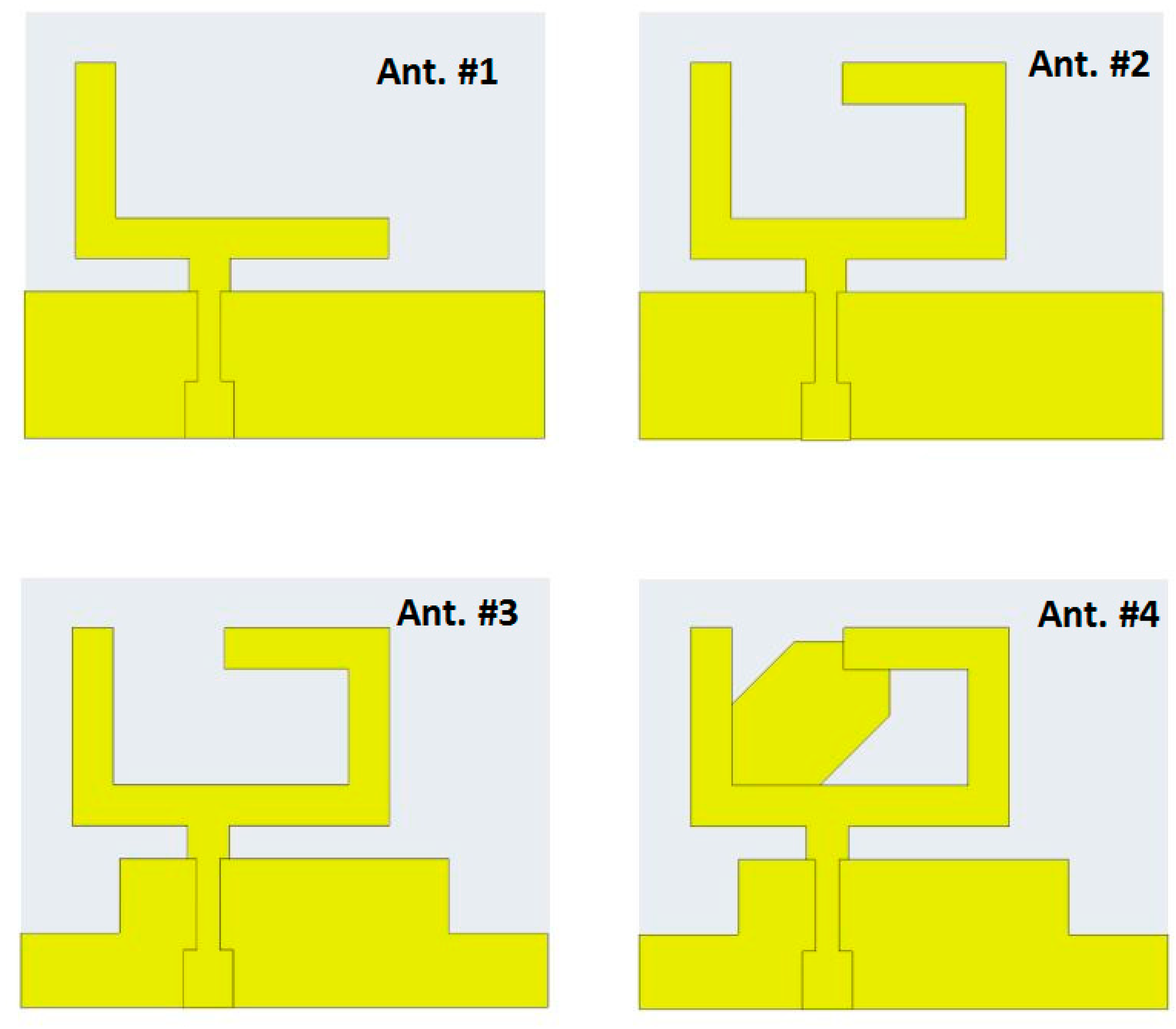
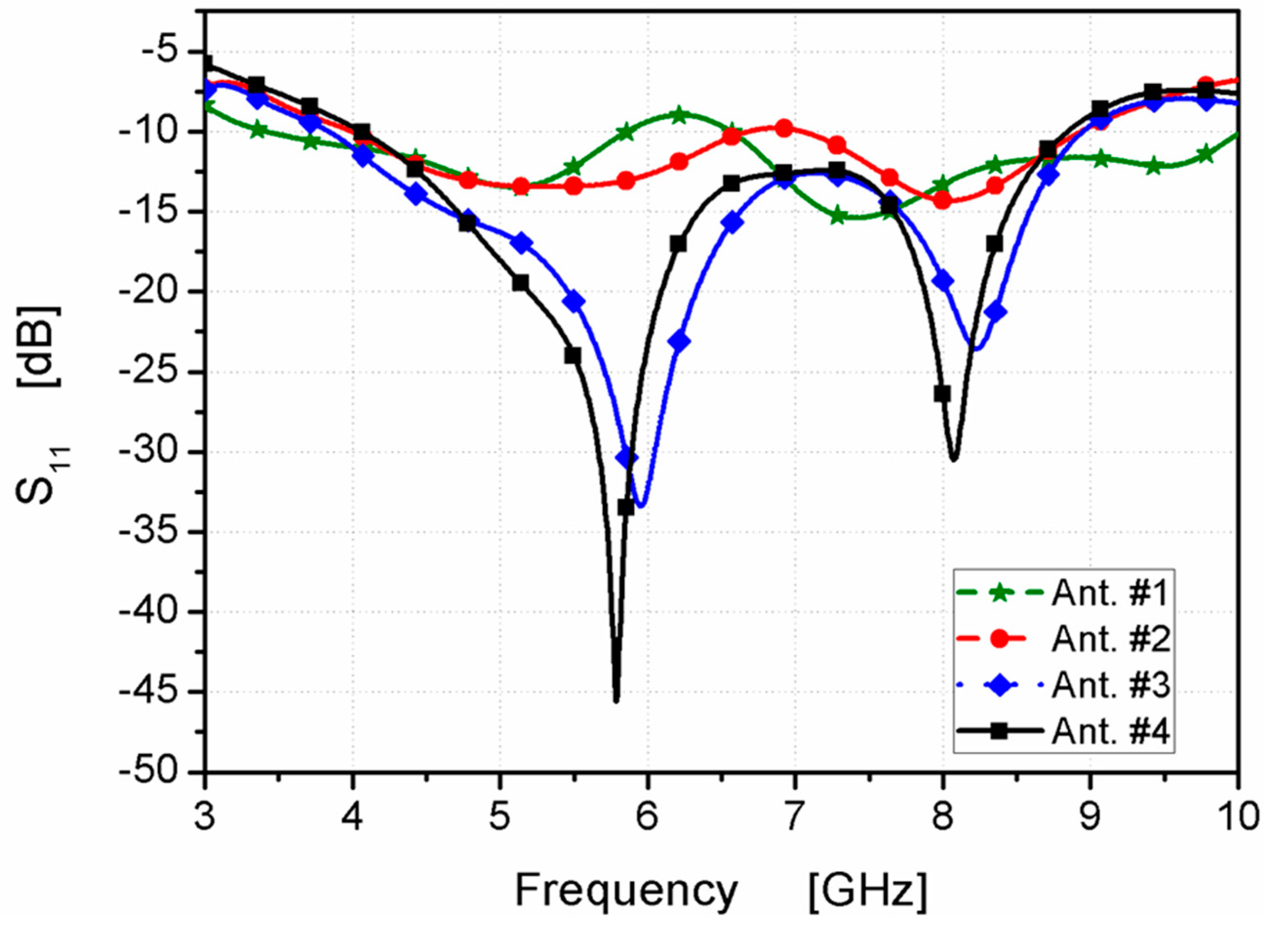
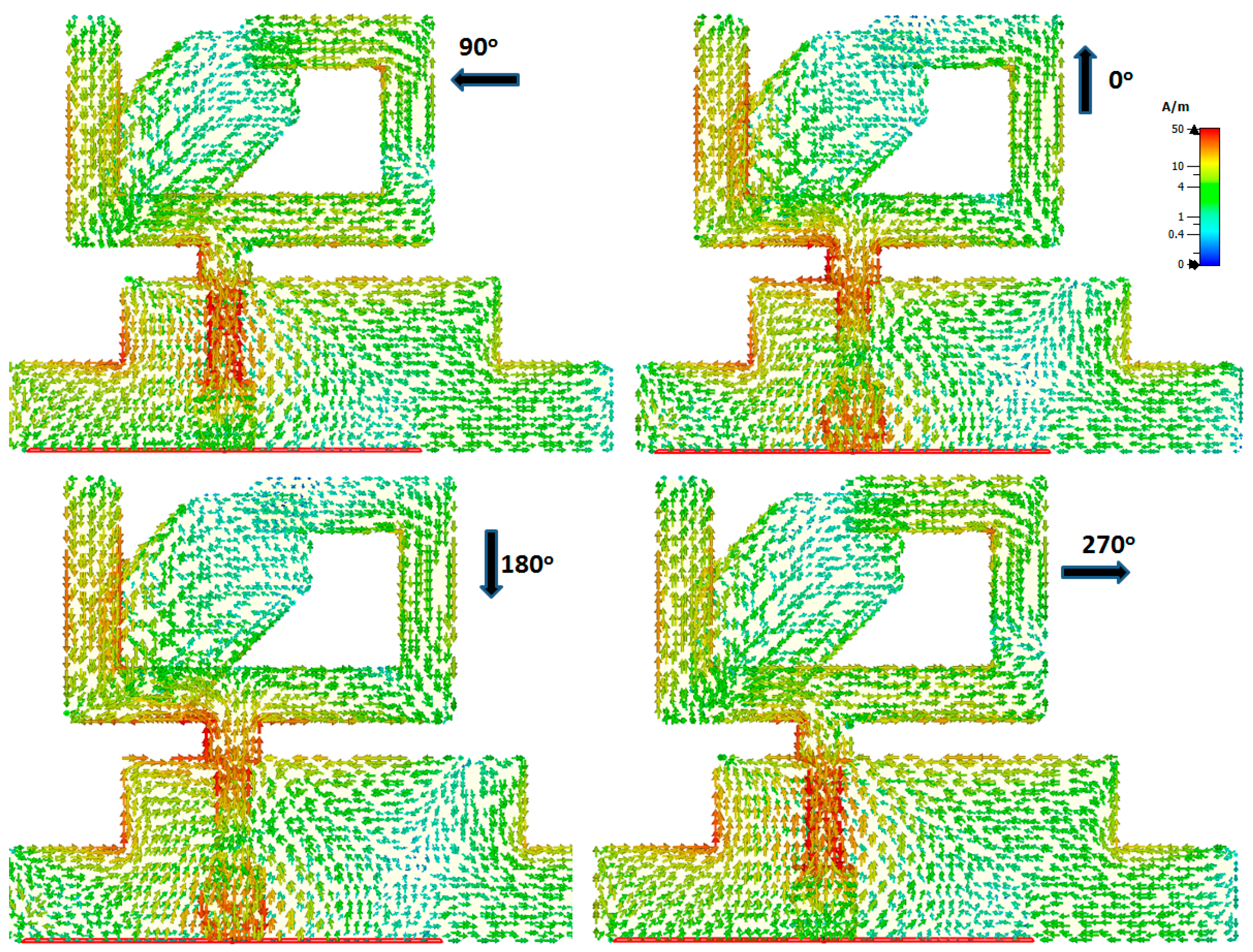
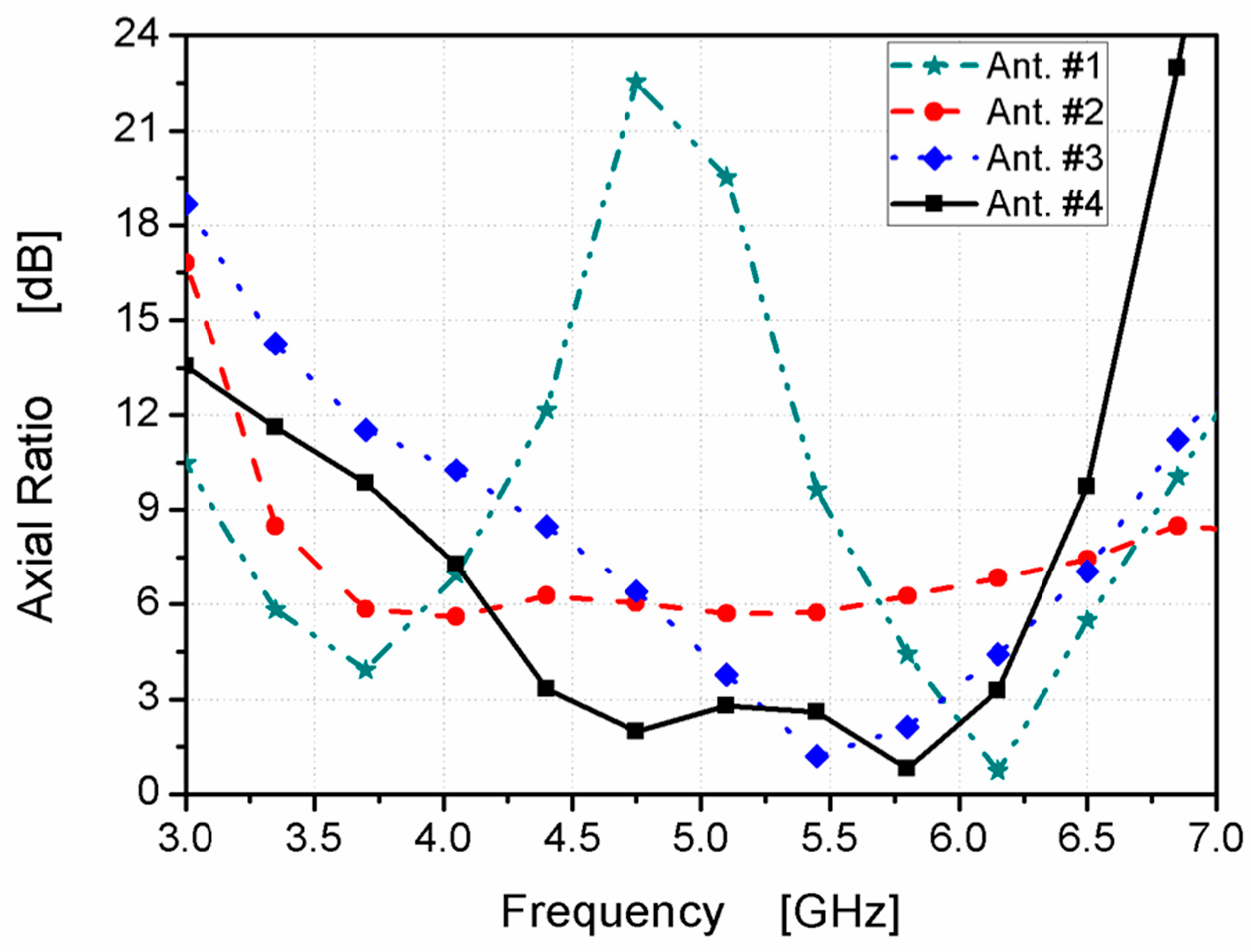
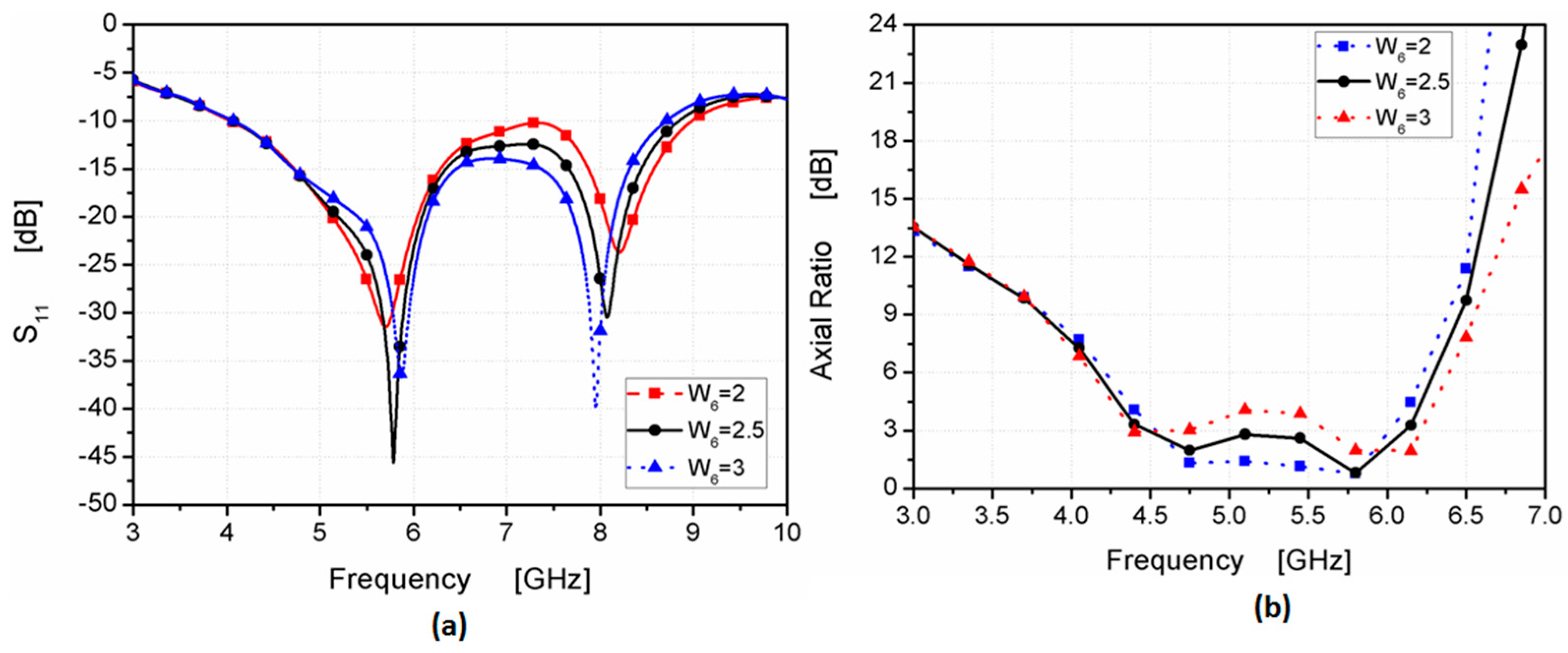
2.2. Analysis and Parametric Study

From the previous section, it can be noticed that the dimension of the quadrilateral-shaped strip can affect the 3 dB AR. Therefore, a parametric study was utilized to show its effect. Figure 6 shows the effect of L4 on the antenna’s performance. By increasing the length of L4 from 1.45 to 7.45 mm, the antenna was operated from 4 to 9 GHz with a good impedance bandwidth as shown in Figure 6a, while the 3 dB AR bandwidth decreased as illustrated in Figure 6b. When L4 = 1.45 mm, the 3 dB AR bandwidth was extended from 4.48 to 4.8 GHz. Additionally, when L4 = 4.45 mm, the 3 dB AR bandwidth was extended from 4.48 to 6.11 GHz. Finally; when L4 = 7.45 mm, the 3 dB AR bandwidth was extended from 4.7 to 5.5 GHz. The length of L4 was chosen to be 4.45 mm.
Furthermore, Figure 7 shows the W6 effect on the antenna’s performance. By increasing the length of W6 from 2 to 3 mm, while keeping L4 = 4.45, the antenna was operated from 4 to 9 GHz with a good impedance bandwidth as illustrated in Figure 7a, while the 3 dB AR bandwidth decreased as shown in Figure 7b. When W6 = 2 mm, the 3 dB AR bandwidth was extended from 4.48 to 6 GHz. Moreover, when W6 = 2.5 mm, the 3 dB AR bandwidth was extended from 4.48 to 6.11 GHz. Finally, when W6 = 3 mm, the 3 dB AR bandwidth was extended from 4.48 to 5 GHz and from 5.6 to 6.2 GHz. The length of W6 was chosen to be 2.5 mm. Finally, by elaborating on the parametric study outcomes, the final dimensions achieved the desired bandwidth from 4 to 9 GHz and satisfied the 3 dB AR bandwidth from 4.48 to 6.11 GHz.

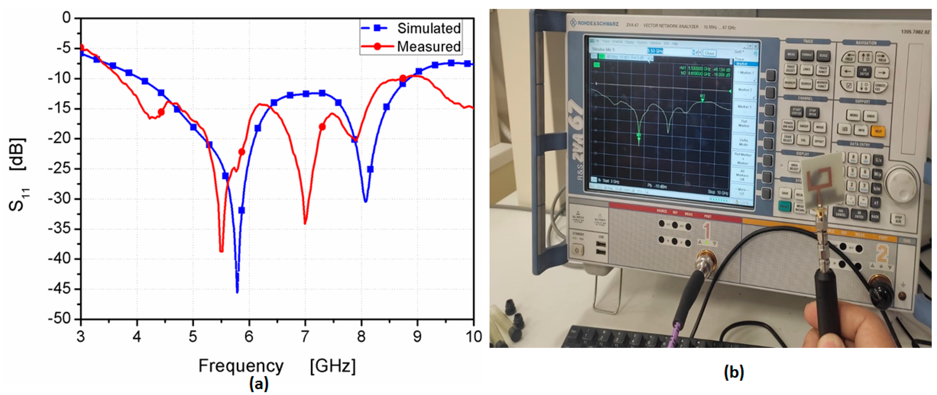
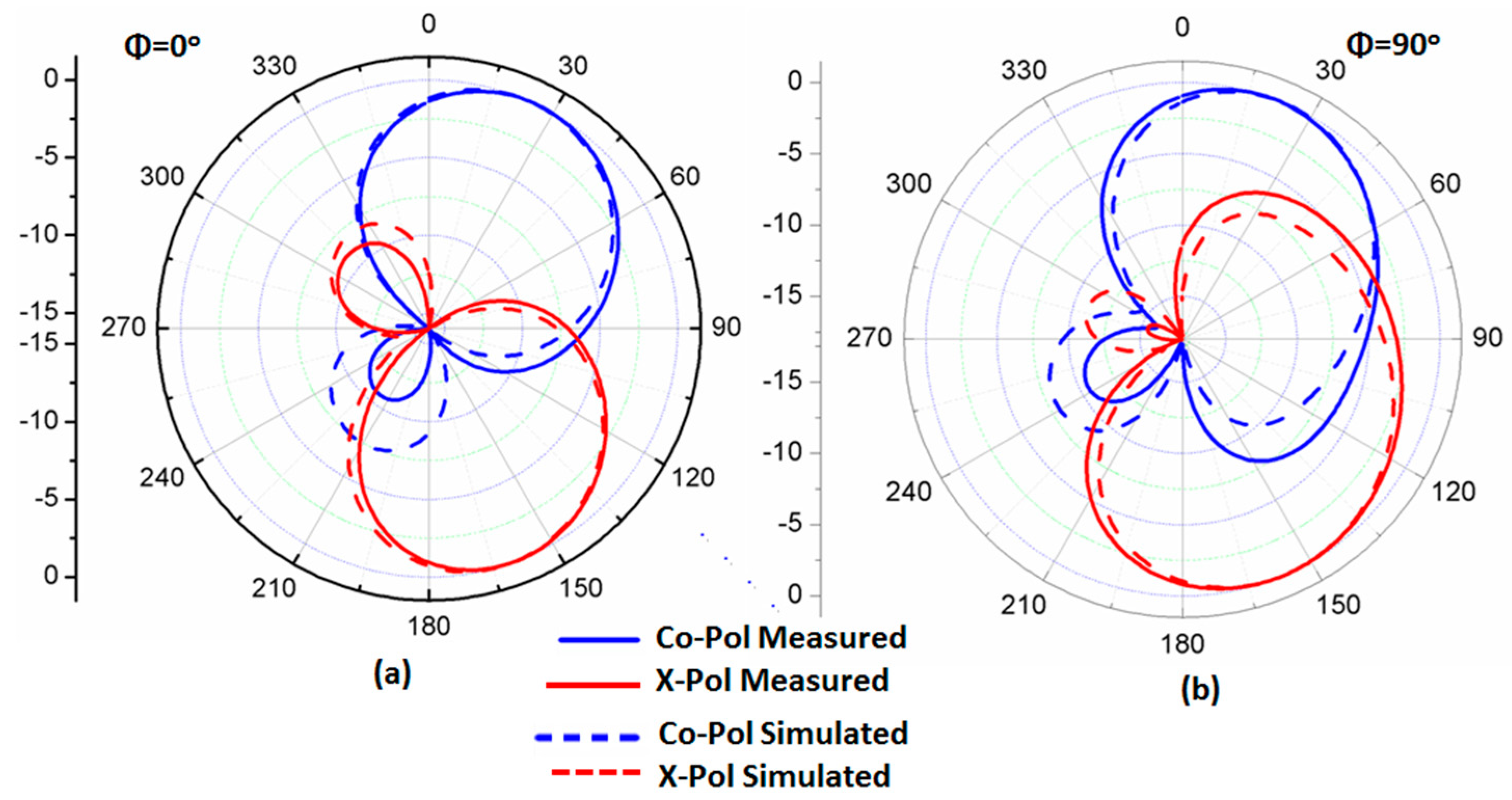
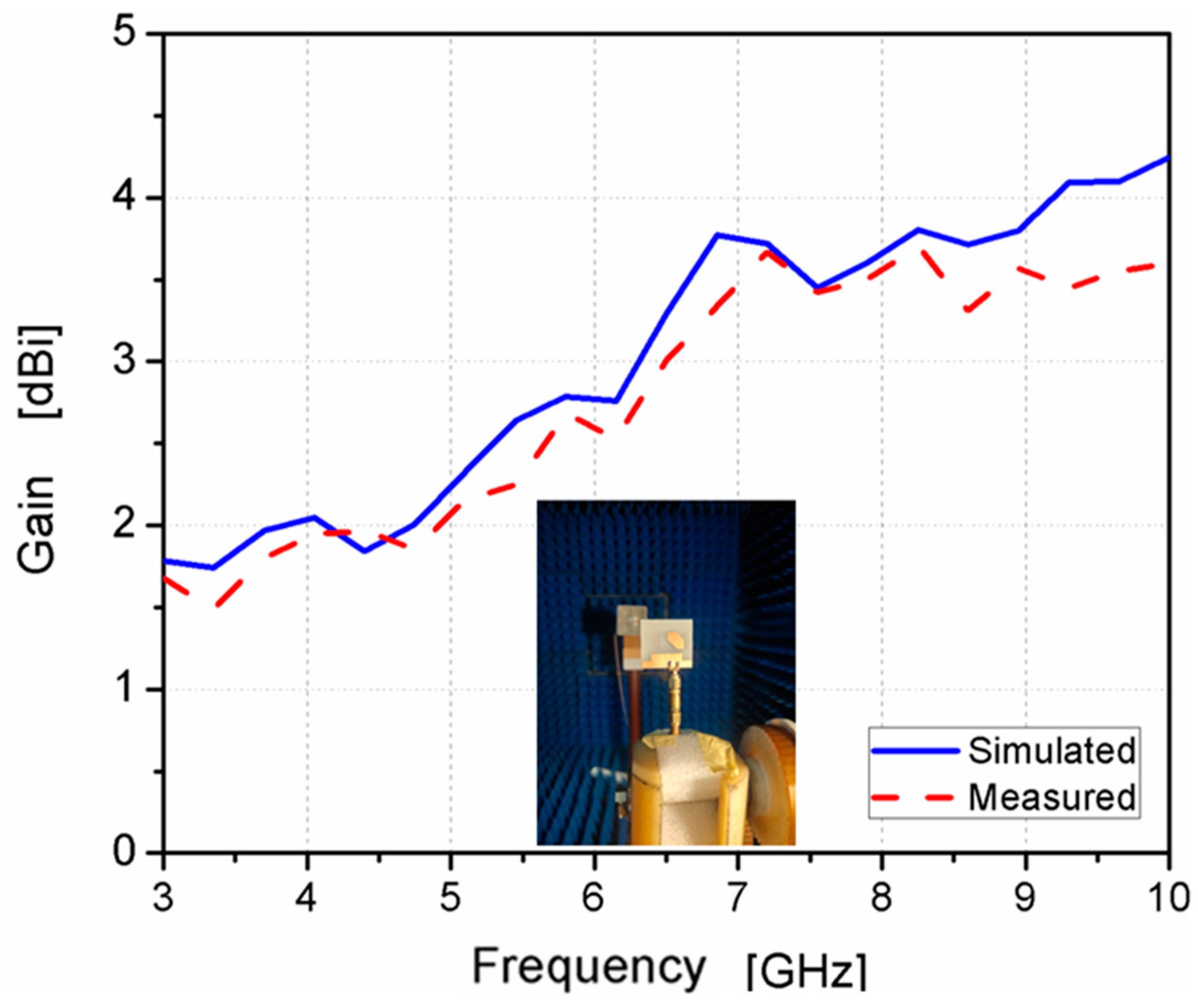
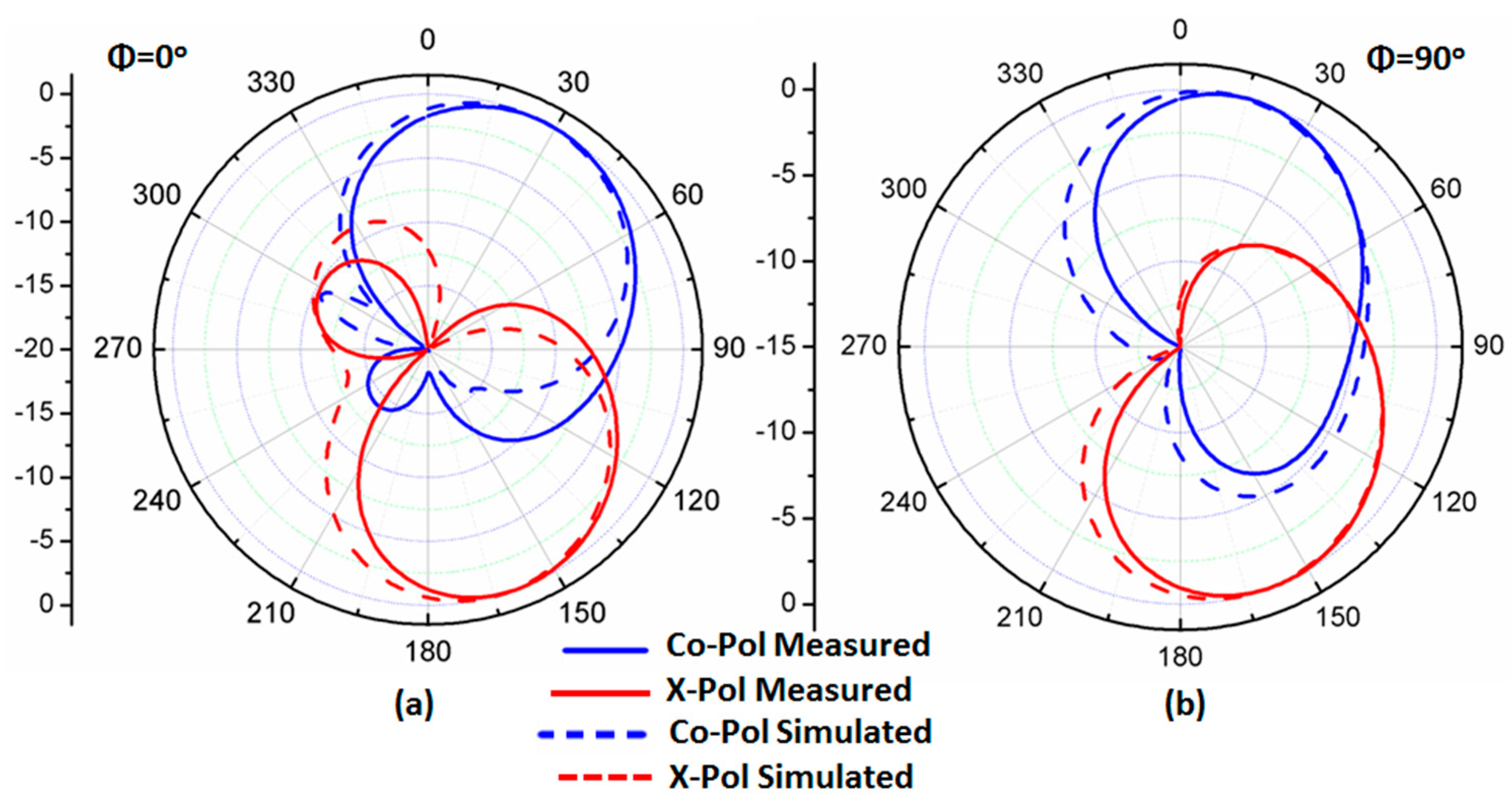
3. Experimental Outcomes and Investigations

The photolithography method was utilized in the fabrication process. Figure 8 shows the prototype layout photo of the suggested antenna in the top and back views. FR4, with a total size of 32 × 30 × 1.6 mm3, and εr = 4.4, tan δ = 0.025 were used in the fabrication. Additionally, it was tested using a vector network analyzer (R&S ZVA 67) to show the reflection coefficient S11, as shown in Figure 9a. The VNA screenshot result of the tested antenna is illustrated in Figure 9b. The tested results show the antenna worked at the frequency band from 3.8–9 GHz (81.25%) with S11 ≤ −10 dB, while the simulated outcomes illustrate that the antenna is operated from 4 to 9 GHz. The two results display good matching between them, with some slight deviations between them due to the fabrication tolerance and SMA soldering process.
The setup of the far-field results was conducted inside an anechoic chamber, as illustrated in Figure 10. A horn antenna operating at a suitable range of frequency and connected to an RF signal generator was utilized as a transmitter antenna. On the other hand, there was a suggested antenna (antenna under test), which was placed inside the same chamber on a supporter that could rotate 360° in both the elevation and horizontal planes. The antenna was connected to a spectrum analyzer to measure the received signal. Additionally, there was a motion controller that controlled the motion of the antenna. The overall equipment, such as the motion controller, spectrum analyzer, and RF generator, was controlled to be operated synchronously. The antenna rotated around its axis with a certain step and stopped for some seconds; on the other hand, the spectrum analyzer measured the received power at this angle during the stopping time. The suggested antenna was rotated in two planes xz (φ = 0°) and yz (φ = 90°) planes. The co- and cross-polarization results at 5.5 and 5.8 GHz are shown in Figure 11a,b and Figure 12a,b, respectively. More than a −15 dB difference between the two components was accomplished in both planes.
The gain of the antenna was measured, as illustrated in Figure 13. It ranged from 1.8 to 3.8 dBi at the designed frequency band with a peak of 3.6 dBi. Moreover, the AR was tested, as displayed in Figure 14, and the achieved 3 dB AR extended from 4.48–6.11 GHz (30.7%) with a reasonable trend between the two outcomes.
Finally, the suggested design was compared with others to evaluate the novelty of the work, as presented in Table 2. The suggested antenna had a more simple design than [3,10,11], a more compact size than [5,9,13,14,15,16,17,18,19,22,23,24,25], a broader bandwidth than [2,9,10,12,15,17,19,21,22,25], and a broader 3 dB AR than [9,10,12,15,19]. Finally, it was deduced that the suggested antenna could be applied in UWB, sub 6 GHz, and WLAN wireless applications.

4. Conclusions

A miniaturized size and wide-band CP monopole antenna was suggested, fabricated, and tested. The suggested antenna was 30 mm × 32 mm (0.4 × 0.42 λ0 at 4 GHz).
A U-shaped radiator on the front side, a partial ground plane with two rectangle slots, and a quadrilateral-shaped parasitic strip on the back side were utilized to produce the CP feature. The CP was achieved when we excited two modes with the same amplitude and a 90° phase difference. This could be generated by regulating the slot’s dimensions and adding a quadrilateral-shaped parasitic strip to the ground plane. The antenna’s different parameters were discussed and investigated. The tested outcomes had a bandwidth of S11 ≤ −10 dB 81.25% (5.2 GHz, 3.8–9 GHz) and an AR bandwidth of 30.7% (1.63 GHz, 4.48–6.11 GHz). Based on the achieved outcomes, it can be suggested that the antenna is considered a good choice for several wireless systems, such as UWB, sub 6 GHz, and WLAN applications.

Author Contributions

Conceptualization, B.M.Y., A.M.A. and A.A.I.; methodology, B.M.Y. and A.A.I.; software, B.M.Y., A.M.A., A.A.I. and M.D.A.; validation, A.A.I. and M.R.; investigation, B.M.Y., A.M.A. and M.D.A.; software, fabrication, and measurements, A.M.A.; writing—original draft preparation, B.M.Y., A.M.A. and A.A.I.; writing—review and editing, B.M.Y., A.M.A., A.A.I., M.D.A. and M.R. All authors have read and agreed to the published version of the manuscript.

Funding

This research received no external funding.

Data Availability Statement

The data will be made available at a reasonable request to the corresponding author.

Acknowledgments

The authors would like to thank Jouf University, KSA for supporting this research.

Conflicts of Interest

The authors declare no conflict of interest.

References

  1. Gao, S.; Luo, Q.; Zhu, F. Circularly Polarized Antennas; Wiley-IEEE Press: New York, NY, USA, 2013. [Google Scholar]
  2. Midya, M.; Bhattacharjee, S.; Mitra, M. Broadband Circularly Polarized Planar Monopole Antenna with G-Shaped Parasitic Strip. IEEE Antennas Wirel. Propag. Lett. 2019, 18, 581–585. [Google Scholar] [CrossRef]
  3. Xu, R.; Shen, Z.; Gao, S.S. Compact-Size Ultra-Wideband Circularly Polarized Antenna with Stable Gain and Radiation Pattern. IEEE Trans. Antennas Propag. 2022, 70, 943–952. [Google Scholar] [CrossRef]
  4. Ding, K.; Gao, C.; Yu, T.; Qu, D. Broadband C-Shaped Circularly Polarized Monopole Antenna. IEEE Trans. Antennas Propag. 2015, 63, 785–790. [Google Scholar] [CrossRef]
  5. Tang, H.; Wang, K.; Wu, R.; Yu, C.; Zhang, J.; Wang, X. A Novel Broadband Circularly Polarized Monopole Antenna Based on C-Shaped Radiator. IEEE Antennas Wirel. Propag. Lett. 2017, 16, 964–967. [Google Scholar] [CrossRef]
  6. So, K.K.; Wong, H.; Luk, K.M.; Chan, C.H. Miniaturized Circularly Polarized Patch Antenna with Low Back Radiation for GPS Satellite Communications. IEEE Trans. Antennas Propag. 2015, 63, 5934–5938. [Google Scholar] [CrossRef]
  7. Ibrahim, A.A.; Zahra, H.; Abbas, S.M.; Ahmed, M.I.; Varshney, G.; Mukhopadhyay, S.; Mahmoud, A. Compact Four-Port Circularly Polarized MIMO X-Band DRA. Sensors 2022, 22, 4461. [Google Scholar] [CrossRef]
  8. Abdelhady, M.; Ahmed, M.I.; Varshney, G.; Ibrahim, A.A. An array of staircase-shaped circularly polarized DRA. Int. J. RF Microw. Comput.-Aided Eng. 2021, 31, e22638. [Google Scholar]
  9. Wei, K.; Li, J.Y.; Wang, L.; Xu, R.; Xing, Z.J. A New Technique to Design Circularly Polarized Microstrip Antenna by Fractal Defected Ground Structure. IEEE Trans. Antennas Propag. 2017, 65, 3721–3725. [Google Scholar] [CrossRef]
  10. Farooqui, M.F.; Kishk, A. 3-D-Printed Tunable Circularly Polarized Microstrip Patch Antenna. IEEE Antennas Wirel. Propag. Lett. 2019, 18, 1429–1432. [Google Scholar] [CrossRef]
  11. Pan, Y.M.; Yang, W.J.; Zheng, S.Y.; Hu, P.F. Design of Wideband Circularly Polarized Antenna Using Coupled Rotated Vertical Metallic Plates. IEEE Trans. Antennas Propag. 2018, 66, 42–49. [Google Scholar] [CrossRef]
  12. Chatterjee, J.; Mohan, A.; Dixit, V. Broadband Circularly Polarized H-Shaped Patch Antenna Using Reactive Impedance Surface. IEEE Antennas Wirel. Propag. Lett. 2018, 17, 625–628. [Google Scholar] [CrossRef]
  13. Li, G.; Zhai, H.; Li, T.; Li, L.; Liang, C. CPW-Fed S-Shaped Slot Antenna for Broadband Circular Polarization. IEEE Antennas Wirel. Propag. Lett. 2013, 12, 619–622. [Google Scholar] [CrossRef]
  14. Xu, R.; Li, J.; Yang, J.; Wei, K.; Qi, Y. A Design of U-Shaped Slot Antenna with Broadband Dual Circularly Polarized Radiation. IEEE Trans. Antennas Propag. 2017, 65, 3217–3220. [Google Scholar] [CrossRef]
  15. Hoang, T.V.; Le, T.T.; Park, H.C. Bandwidth improvement of a circularly polarised printed monopole antenna using a lumped capacitor. Electron. Lett. 2016, 52, 1091–1092. [Google Scholar] [CrossRef]
  16. Alsariera, H.; Zakaria, Z.; Awang Md Isa, A. A Broadband P-Shaped Circularly Polarized Monopole Antenna with a Single Parasitic Strip. IEEE Antennas Wirel. Propag. Lett. 2019, 18, 2194–2198. [Google Scholar] [CrossRef]
  17. Fujimoto, T.; Kozo, J. Wideband rectangular printed monopole antenna for circular polarisation. IET Microw. Antennas Propag. 2014, 8, 649–656. [Google Scholar] [CrossRef]
  18. Ding, K.; Gao, C.; Wu, Y.; Qu, D.; Zhang, B. A Broadband Circularly Polarized Printed Monopole Antenna with Parasitic Strips. IEEE Antennas Wirel. Propag. Lett. 2017, 16, 2509–2512. [Google Scholar] [CrossRef]
  19. Ghobadi, A.; Dehmollaian, M. A Printed Circularly Polarized Y-Shaped Monopole Antenna. IEEE Antennas Wirel. Propag. Lett. 2012, 11, 22–25. [Google Scholar] [CrossRef]
  20. Jhajharia, T.; Tiwari, V.; Yadav, D.; Rawat, S.; Bhatnagar, D. Wideband circularly polarized antenna with an asymmetric meandered-shaped monopole and defected ground structure for wireless communication. IET Microw. Antennas Propag. 2018, 12, 1554–1558. [Google Scholar] [CrossRef]
  21. Gyasi, K.O.; Wen, G.; Inserra, D.; Huang, Y.; Li, J.; Ampoma, A.E.; Zhang, H. A Compact Broadband Cross-Shaped Circularly Polarized Planar Monopole Antenna with a Ground Plane Extension. IEEE Antennas Wirel. Propag. Lett. 2018, 17, 335–338. [Google Scholar] [CrossRef]
  22. Mousavi, P.; Miners, B.; Basir, O. Wideband L-Shaped Circular Polarized Monopole Slot Antenna. IEEE Antennas Wirel. Propag. Lett. 2010, 9, 822–825. [Google Scholar] [CrossRef]
  23. Le, T.T.; Park, H.C. Very simple circularly polarized printed patch antenna with enhanced bandwidth. Electron. Lett. 2014, 50, 1896–1898. [Google Scholar] [CrossRef]
  24. Ding, K.; Guo, Y.-X.; Gao, C. CPW-Fed Wideband Circularly Polarized Printed Monopole Antenna with Open Loop and Asymmetric Ground Plane. IEEE Antennas Wirel. Propag. Lett. 2017, 16, 833–836. [Google Scholar] [CrossRef]
  25. Midya, M.; Bhattacharjee, S.; Mitra, M. Pair of grounded L strips loaded broadband circularly polarized square slot antenna with enhanced axial ratio bandwidth. Electron. Lett. 2018, 54, 917–918. [Google Scholar] [CrossRef]
Figure 1. The antenna’s complete geometrical configuration.
Micromachines 14 01308 g001
Figure 2. The antenna design improvement procedures.
Micromachines 14 01308 g002
Figure 3. S11 outcomes of the designed four antennas.
Micromachines 14 01308 g003
Figure 4. ARs of the designed four antennas.
Micromachines 14 01308 g004
Figure 5. Surface current density at 5.8 GHz during different orthogonal phases.
Micromachines 14 01308 g005
Figure 6. The L4 influence on antenna performance (a) S11; (b) AR.
Micromachines 14 01308 g006
Figure 7. The W6 influence on antenna performance (a) S11; (b) AR.
Micromachines 14 01308 g007
Figure 8. Fabricated prototype layout of suggested antenna.
Micromachines 14 01308 g008
Figure 9. The S11 results of the suggested antenna: (a) simulated and measured (b) VNA screenshot.
Micromachines 14 01308 g009
Figure 10. The setup of the radiation pattern measurement.
Micromachines 14 01308 g010
Figure 11. The radiation pattern normalized outcomes at 5.5 GHz (a) φ = 0°; (b) φ = 90°.
Micromachines 14 01308 g011
Figure 12. The radiation pattern normalized outcomes at 5.8 GHz (a) φ = 0°; (b) φ = 90°.
Micromachines 14 01308 g012
Figure 13. The antenna’s realized gain.
Micromachines 14 01308 g013
Figure 14. The antenna AR’s measured and simulated outcomes.
Micromachines 14 01308 g014
Table 1. The antenna dimensions.
ParameterLength [mm]ParameterLength [mm]ParameterLength [mm]
L s u b 30 L 3 4.5 L g 2.8
L p 12 L 4 4.45 h 1.6
L f 11 L 5 5.77 W s u b 32
L 1 3.5 L 6 2.5 W p 19.25
L 2 5.5 L g n d 9 W f 3
W 1 1.4 W 3 6 W 5 4.45
W 2 2.5 W 4 5.77 W 6 2.5
W 7 10 d 9.9
Table 2. The suggested design in comparison with other works.
Refs.Size (mm2)εr/h (mm)f0/BW (%)AR (%)Gain (dBi)Complexity
[2]30 × 324.4/1.65.72/62.9453.923.6Simple
[3]120 × 1203.55/0.8134.55/120.9133.311.2Complex
[5]49 × 554.4/1.54.3/106.3104.76.55Simple
[9]45 × 4510/3.181.575/1.90.42.2Simple
[10]80 × 802.7/91.9/27.234.3Complex
[11]90 × 903.38/0.82/115.2106.17Complex
[12]32 × 323.38/5.5885.5/44.527.57.2Complex
[13]54 × 542.55/14/10458.63.8Simple
[14]48 × 484.4/14.2/114.4110.54.5Simple
[15]52 × 552.2/1.525.4/60.530.74.8Simple
[16]35 × 424.4/1.63.95/118104.45.2Simple
[17]70 × 704.7/3.22.45/51.456.22Simple
[18]50 × 554.4/13.4/8864.72.25Simple
[19]50 × 552.2/3.12.45/28.642.9Simple
[20]32 × 394.4/1.54.9/10237.52.25Simple
[21]30 × 304.4/16.3/55.542.65.3Simple
[25]40 × 404.4/1.67.9/73.3958.084.22Simple
[22]70 × 704.3/0.81.7/30322.45Simple
[23]50 × 503.5/1.525.8/10149.84.36Simple
[24]50 × 554.4/12.86/96.563.33.5Simple
This work30 × 324.4/1.66.4/81.2530.73.8Simple
Disclaimer/Publisher’s Note: The statements, opinions and data contained in all publications are solely those of the individual author(s) and contributor(s) and not of MDPI and/or the editor(s). MDPI and/or the editor(s) disclaim responsibility for any injury to people or property resulting from any ideas, methods, instructions or products referred to in the content.

