
Long Stroke Design of Piezoelectric Walking Actuator for Wafer Probe Station


Abstract
:1. Introduction
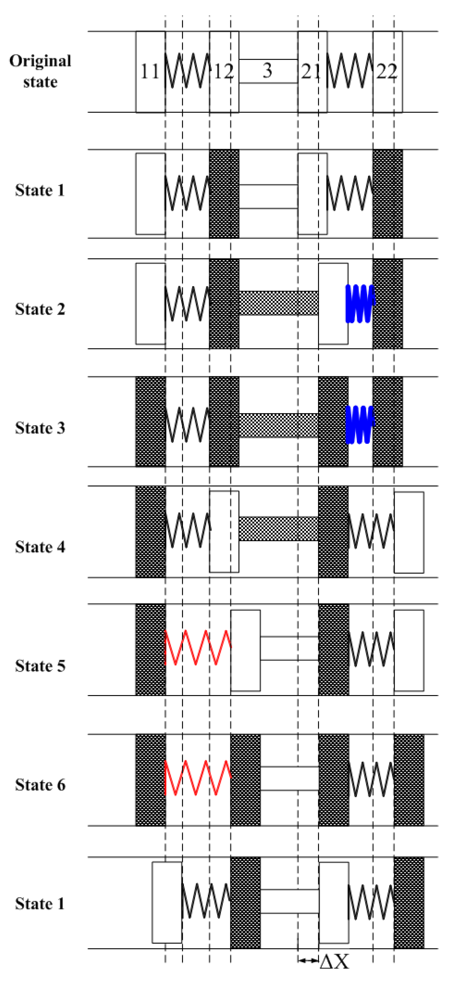
2. Principle
3. Prototype Investigation
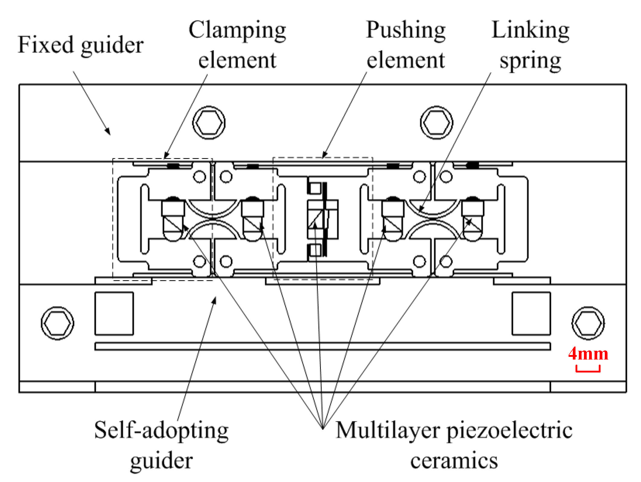
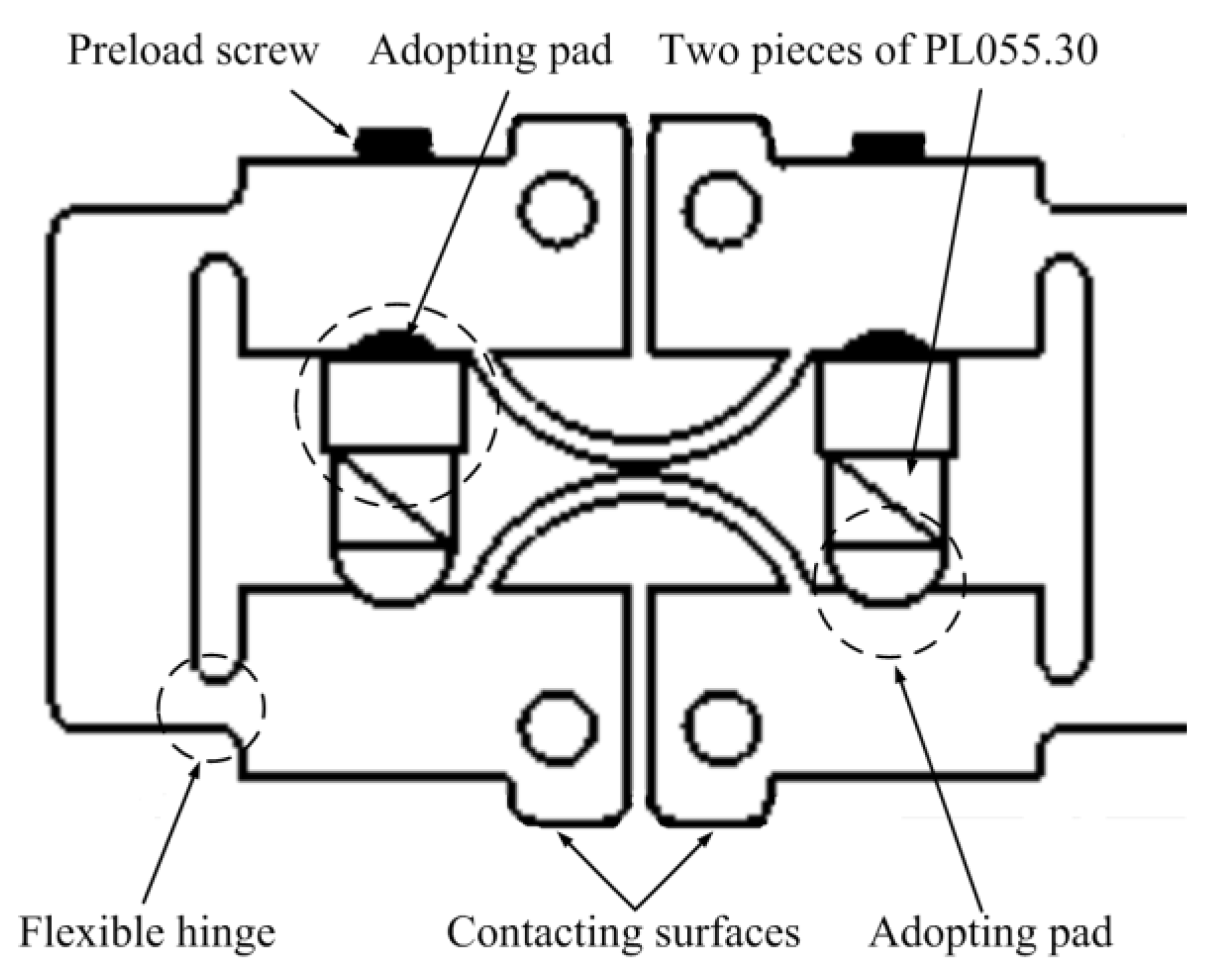
3.1. Structure Design
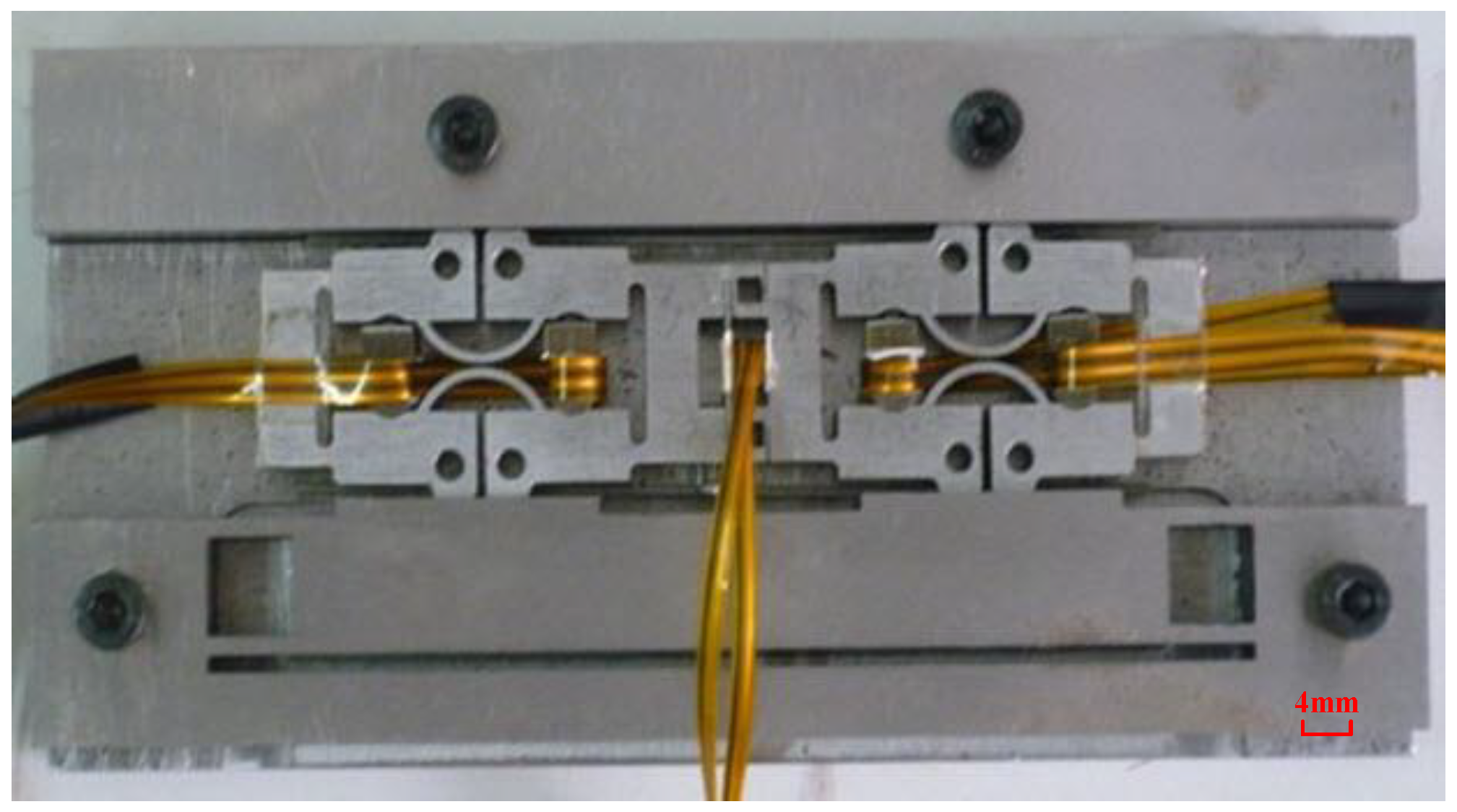
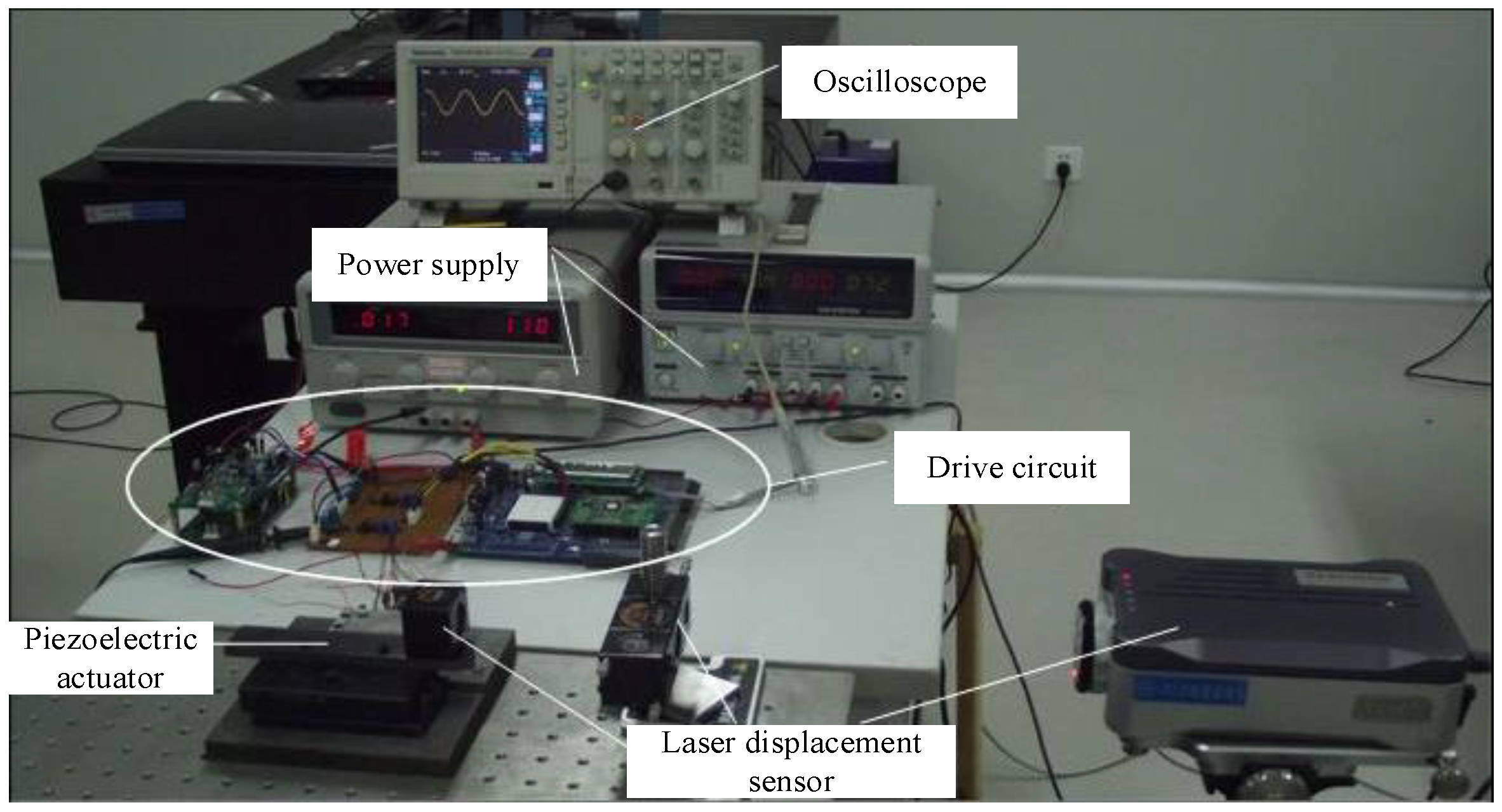
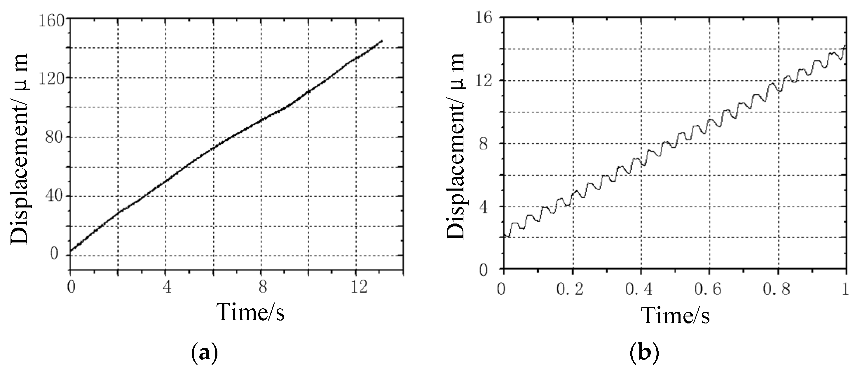
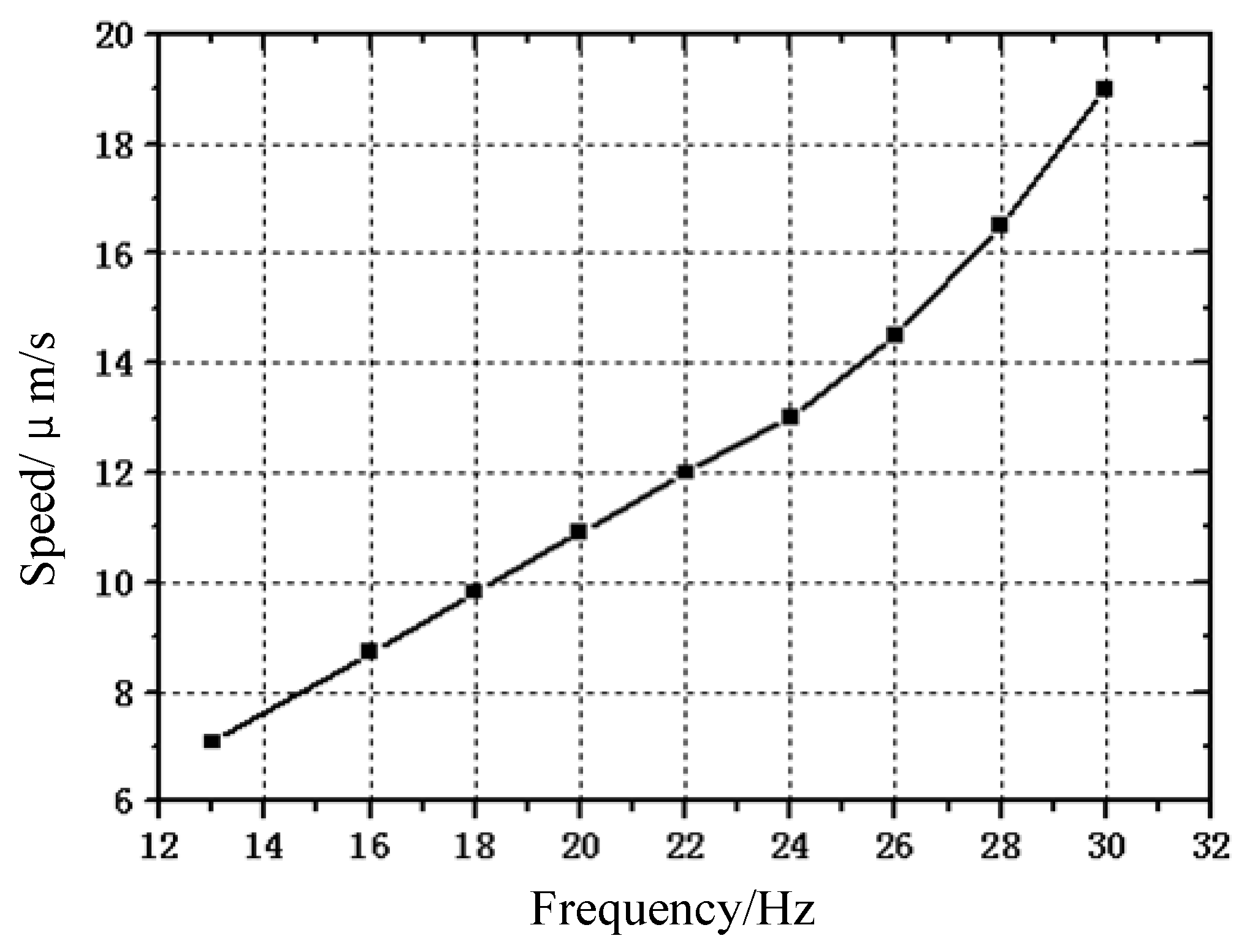
3.2. Experimental Verification
4. Conclusions
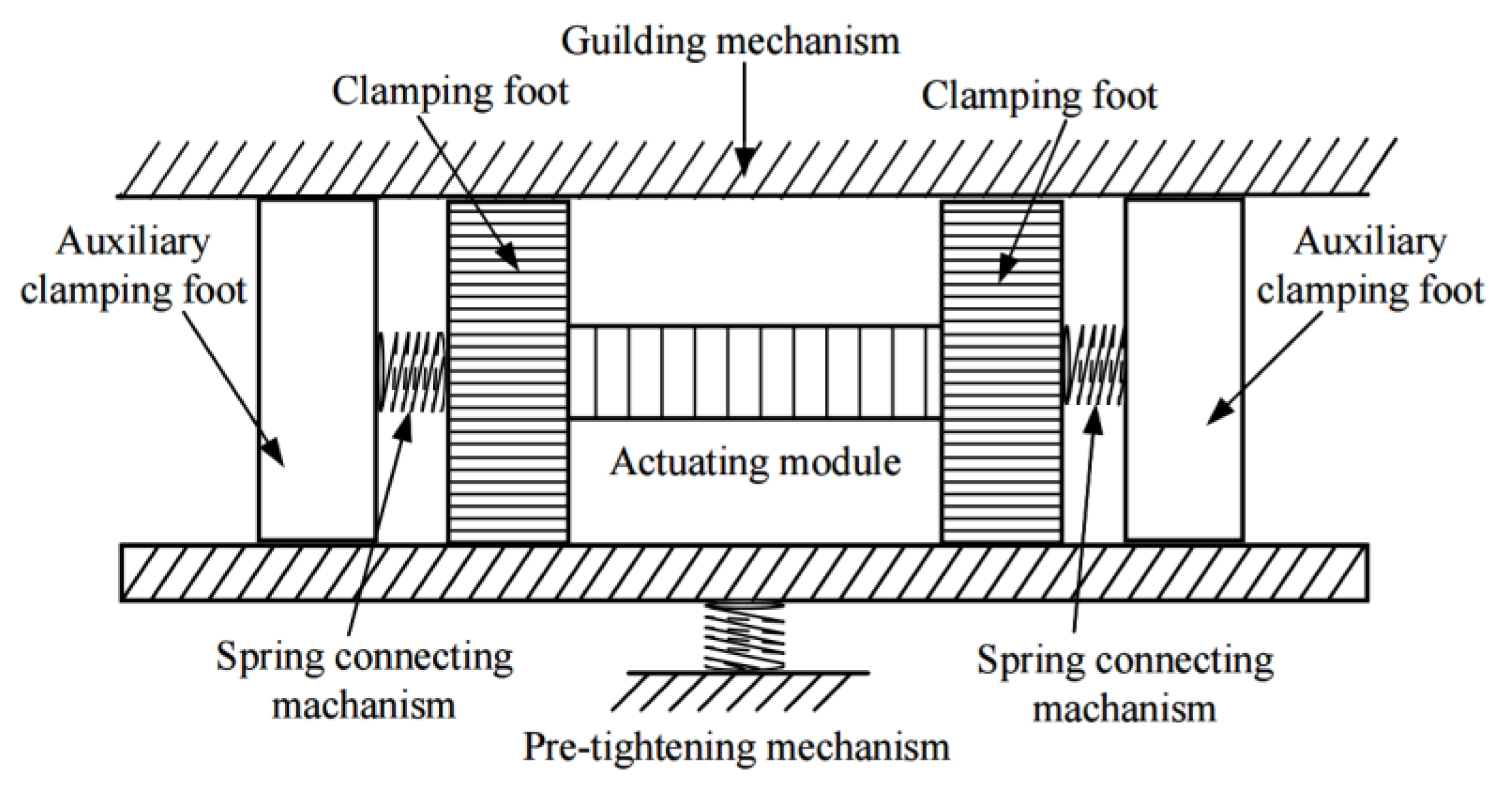
- The operation stability of the actuator is improved. The actuator has the same clamping force whether it is powered on or off. Even if the parallelism of the guide rails on both sides is not high, the differential clamping feet close to each other can still operate normally;
- The cost of the actuator is reduced. Laminated piezoelectric ceramic is the core component of the actuator. Due to the use of differential clamping, the clamping can be realized by using laminated piezoelectric ceramic with a small volume;
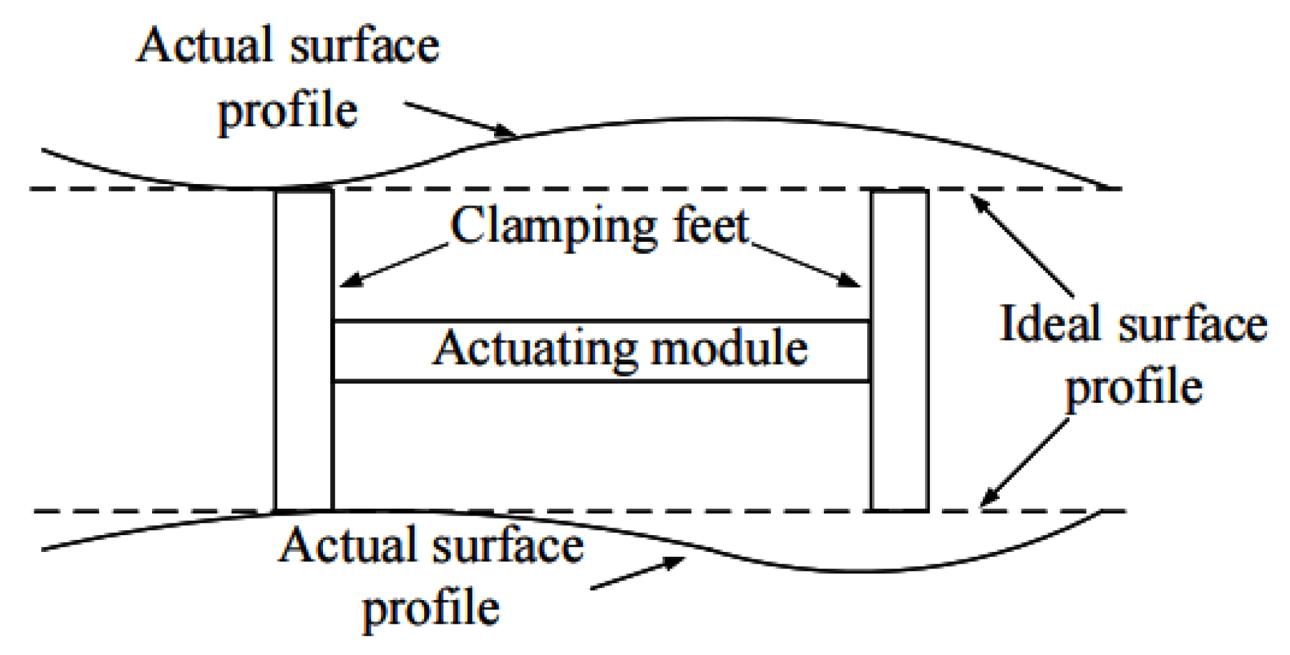
- The actuating stroke of the actuator is increased. With the traditional design, it is often difficult to realize the action of large stroke because the parallelism of the guide mechanism is not high. The above design reduces the requirements for the parallelism of the guide rail and can realize stable operation in a large stroke range.
Author Contributions
Funding
Data Availability Statement
Conflicts of Interest
References
- Russell, D.; Cleary, K.; Reeves, R. Cryogenic probe station for on-wafer characterization of electrical devices. Rev. Sci. Instrum. 2012, 83, 44703. [Google Scholar] [CrossRef] [PubMed] [Green Version]
- Bauwens, M.F.; Alijabbari, N.; Lichtenberger, A.W.; Barker, N.S.; Weikle, R.M. A 1.1 THz micromachined on-wafer probe. In Proceedings of the 2014 IEEE MTT-S International Microwave Symposium (IMS2014), Tampa Bay, FL, USA, 3–5 June 2014; pp. 1–4. [Google Scholar]
- El Fellahi, A.; Haddadi, K.; Marzouk, J.; Arscott, S.; Boyaval, C.; Lasri, T.; Dambrine, G. Nanorobotic RF probe station for calibrated on-wafer measurements. In Proceedings of the 2015 European Microwave Conference (EuMC), Paris, France, 7–10 September 2015; pp. 163–166. [Google Scholar]
- Čeponis, A.; Mažeika, D.; Jūrėnas, V. 2-DOF Small-Size Piezoelectric Locomotion Platform with the Unlimited Motion Range. Micromachines 2021, 12, 1396. [Google Scholar] [CrossRef] [PubMed]
- Xu, D.; Liu, Y.; Shi, S.; Liu, J.; Chen, W.; Wang, L. Development of a Nonresonant Piezoelectric Motor with Nanometer Res-olution Driving Ability. IEEE/ASME Trans. Mechatron. 2018, 23, 444–451. [Google Scholar] [CrossRef]
- Wischnewski, M.; Delibas, B.; Wischnewski, A. Piezoelectric motor operated both in resonance and DC modes. In Proceedings of the ACTUATOR International Conference and Exhibition on New Actuator Systems and Applications, Online, 17–19 February 2021; pp. 1–4. [Google Scholar]
- Zhao, C. Ultrasonic Motors Technologies and Applications; Springer: Berlin/Heidelberg, Germany, 2011. [Google Scholar]
- Chunsheng, Z. Introduction. In Ultrasonic Motors: Technologies and Applications, 1st ed.; Science Press: Beijing, China, 2011; pp. 7–8. [Google Scholar]
- Liu, Y.; Deng, J.; Su, Q. Review on Multi-Degree-of-Freedom Piezoelectric Motion Stage. IEEE Access 2018, 6, 59986–60004. [Google Scholar] [CrossRef]
- Tian, X.; Liu, Y.; Deng, J.; Wang, L.; Chen, W. A review on piezoelectric ultrasonic motors for the past decade: Classification, operating principle, performance, and future work perspectives. Sens. Actuators A Phys. 2020, 306, 111971. [Google Scholar] [CrossRef]
- Ye, Z.; Zhou, C.; Jin, J.; Yu, P.; Wang, F. A novel ring-beam piezoelectric actuator for small-size and high-precision manipulator. Ultrasonics 2019, 96, 90–95. [Google Scholar] [CrossRef]
- Huang, J.; Sun, D. Performance Analysis of a Travelling-Wave Ultrasonic Motor under Impact Load. Micromachines 2020, 11, 689. [Google Scholar] [CrossRef] [PubMed]
- Zhang, J.; Shi, Y.; Niu, Z.; Liang, D. Turned off Characteristics of Linear Ultrasonic Motor. Trans. Nanjing Univ. Aero. Astro. 2017, 34, 49–54. [Google Scholar]
- Li, J.; Wang, Y.; Chen, Z.; Cheng, F.; Yu, Q. A Compact Linear Ultrasonic Motor Composed by Double Flexural Vibrator. Micromachines 2021, 12, 958. [Google Scholar] [CrossRef]
- Li, X.; Yao, Z. Analytical modeling and experimental validation of a V-shape piezoelectric ultrasonic transducer. Smart Mater. Struct. 2016, 25, 75026. [Google Scholar] [CrossRef]
- Wang, L.; Hofmann, V.; Bai, F.; Jin, J.; Twiefel, J. Modeling of coupled longitudinal and bending vibrations in a sandwich type piezoelectric transducer utilizing the transfer matrix method. Mech. Syst. Signal Process. 2018, 108, 216–237. [Google Scholar] [CrossRef]
- Chen, N.; Zheng, J.; Jiang, X.; Fan, S.; Fan, D. Analysis and control of micro-stepping characteristics of ultrasonic motor. Front. Mech. Eng. 2020, 15, 585–599. [Google Scholar] [CrossRef] [Green Version]
- Takemura, K.; Maeno, T. Design and control of an ultrasonic motor capable of generating multi-DOF motion. IEEE/ASME Trans. Mechatron. 2001, 6, 499–506. [Google Scholar] [CrossRef] [Green Version]
- Koc, B.; Delibas, B. Method for Closed-Loop Motion Control for an Ultrasonic Motor. USA Patent 16/633, 940, 25 June 2020. [Google Scholar]
- Feng, Z.; Liang, W.; Ling, J.; Xiao, X.; Tan, K.K.; Lee, T.H. Integral terminal sliding-mode-based adaptive integral backstepping control for precision motion of a piezoelectric ultrasonic motor. Mech. Syst. Signal Process. 2020, 144, 106856. [Google Scholar] [CrossRef]
- Wang, L.; Chen, W.; Liu, J.; Deng, J.; Liu, Y. A review of recent studies on non-resonant piezoelectric actuators. Mech. Syst. Signal Process. 2019, 133, 106254. [Google Scholar] [CrossRef]
- Peng, Y.; Peng, Y.; Gu, X.; Wang, J.; Yu, H. A review of long range piezoelectric motors using frequency leveraged method. Sens. Actuators A Phys. 2015, 235, 240–255. [Google Scholar] [CrossRef]
- Hu, Y.; Wang, R.; Wen, J.; Liu, J.-Q. A Low-Frequency Structure-Control-Type Inertial Actuator Using Miniaturized Bimorph Piezoelectric Vibrators. IEEE Trans. Ind. Electron. 2019, 66, 6179–6188. [Google Scholar] [CrossRef]
- Chen, K.; Wen, J.; Cheng, G.; Ma, J.; Zeng, P. An asymmetrical inertial piezoelectric rotary actuator with the bias unit. Sens. Actuators A Phys. 2016, 251, 179–187. [Google Scholar] [CrossRef]
- Neuman, J.; Nováček, Z.; Pavera, M.; Zlámal, J.; Kalousek, R.; Spousta, J.; Dittrichová, L.; Šikola, T. Experimental optimization of power-function-shaped drive pulse for stick-slip piezo actuators. Precis. Eng. 2015, 42, 187–194. [Google Scholar] [CrossRef]
- Zhou, M.; Ruan, Y.; Liu, W.; Huang, S.; Fu, X. A bio-inspired piezoelectric motor with simple structured asymmetric stator. Smart Mater. Struct. 2014, 23, 45003. [Google Scholar] [CrossRef]
- Sangchap, M.; Tahmasebipour, M.; Tahmasebipour, Y. A Linear Inchworm Piezomotor with a New Configuration: Design Considerations, Fabrication and Characterization. Iran. J. Sci. Technol. Trans. Mech. Eng. 2020, 46, 149–160. [Google Scholar] [CrossRef]
- Dong, H.; Li, T.; Wang, Z.; Ning, Y. Design and experiment of a piezoelectric actuator based on inchworm working principle. Sens. Actuators A Phys. 2020, 306, 111950. [Google Scholar] [CrossRef]
- Kwon, H.N.; Jeong, S.H.; Lee, S.K.; Lee, J.H. Design and characterization of a micromachined inchworm motor with thermoelastic linkage actuators. Sens. Actuators A Phys. 2003, 103, 143–149. [Google Scholar] [CrossRef]
- Hemsel, T.; Wallaschek, J. Survey of the present state of the art of piezoelectric linear motors. Ultrasonics 2000, 38, 37–40. [Google Scholar] [CrossRef]
- Li, J.; Sedaghati, R.; Dargahi, J.; Waechter, D. Design and development of a new piezoelectric linear Inchworm actuator. Mechatronics 2005, 15, 651–681. [Google Scholar] [CrossRef]
- Oh, C.-H.; Choi, J.-H.; Nam, H.-J.; Bu, J.-U.; Kim, S.-H. Ultra-compact, zero-power magnetic latching piezoelectric inchworm motor with integrated position sensor. Sens. Actuators A Phys. 2010, 158, 306–312. [Google Scholar] [CrossRef]
- Marth, H. Waldbronn. Piezo Linear Drive with a Group of Piezo Actuator Stacks as Well as Method for Operating Such a Drive. USA Patent 10/166, 660, 5 October 2004. [Google Scholar]
- Piezo Motors. Available online: https://www.dynamic-structures.com/piezo-motors (accessed on 14 February 2022).


| Dimensions (mm) | Nominal Displacement (μm@100 V) ± 20% | Blocking Force (N) | Electrical Capacitance (nF) ± 20% | Resonance Frequency (kHz) |
|---|---|---|---|---|
| 5 × 5 × 2 | 2.2 | >500 | 250 | >300 |
| Element | Before Assembly | After Assembly |
|---|---|---|
| 11 | 7.3 | 3.9 |
| 12 | 7.6 | 5 |
| 3 | 3.8 | - |
| 21 | 5.7 | 3.8 |
| 22 | 6.7 | 4.6 |
Publisher’s Note: MDPI stays neutral with regard to jurisdictional claims in published maps and institutional affiliations. |
© 2022 by the authors. Licensee MDPI, Basel, Switzerland. This article is an open access article distributed under the terms and conditions of the Creative Commons Attribution (CC BY) license (https://creativecommons.org/licenses/by/4.0/).
Share and Cite
Yang, C.; Wang, Y.; Fan, W. Long Stroke Design of Piezoelectric Walking Actuator for Wafer Probe Station. Micromachines 2022, 13, 412. https://doi.org/10.3390/mi13030412
Yang C, Wang Y, Fan W. Long Stroke Design of Piezoelectric Walking Actuator for Wafer Probe Station. Micromachines. 2022; 13(3):412. https://doi.org/10.3390/mi13030412
Chicago/Turabian StyleYang, Cheng, Yin Wang, and Wei Fan. 2022. "Long Stroke Design of Piezoelectric Walking Actuator for Wafer Probe Station" Micromachines 13, no. 3: 412. https://doi.org/10.3390/mi13030412
APA StyleYang, C., Wang, Y., & Fan, W. (2022). Long Stroke Design of Piezoelectric Walking Actuator for Wafer Probe Station. Micromachines, 13(3), 412. https://doi.org/10.3390/mi13030412