
Commutation Torque Ripple Reduction Strategy of Brushless DC Motor Drives Based on Boosting Voltage of DC-Link Small Capacitor


Abstract
:1. Introduction
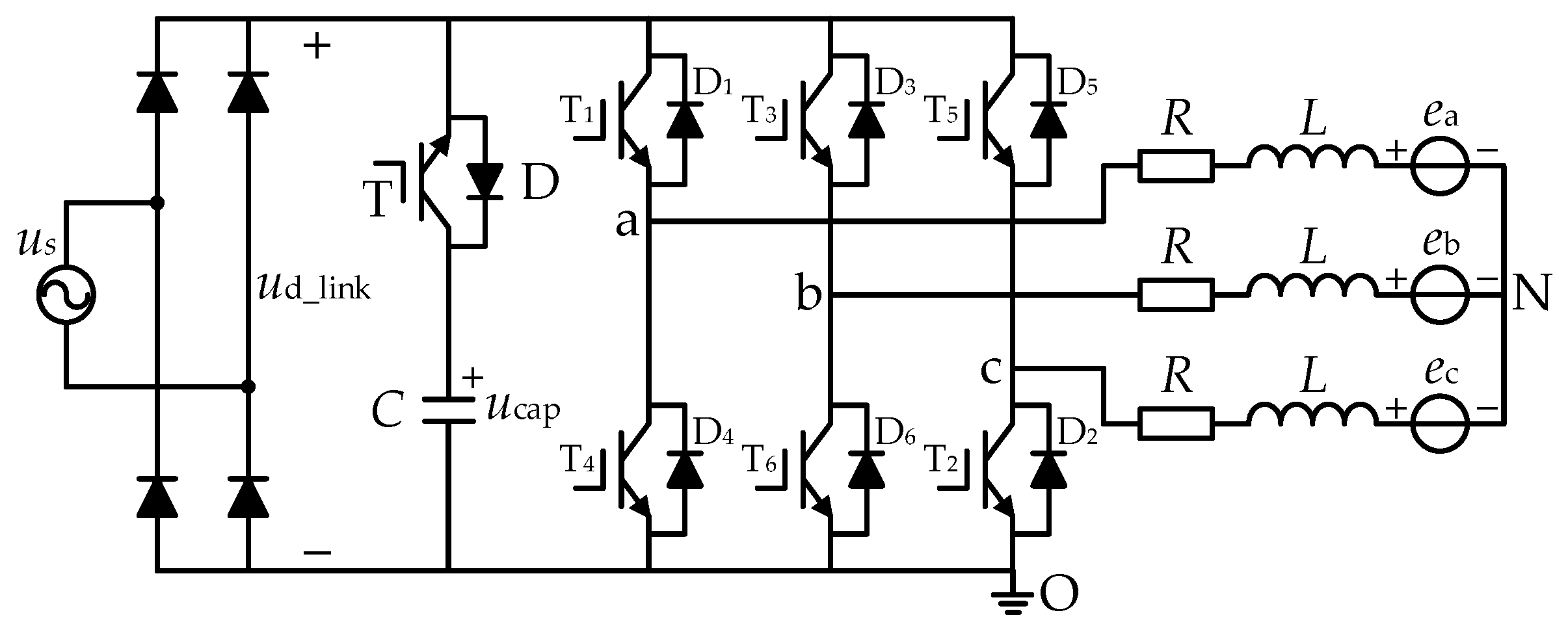
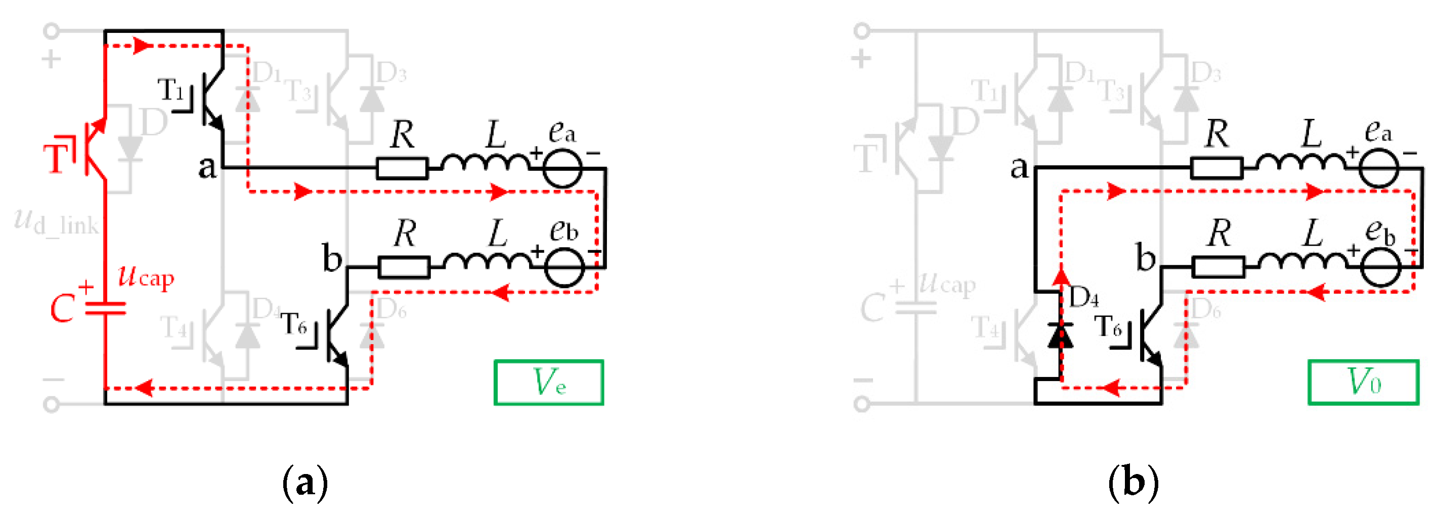
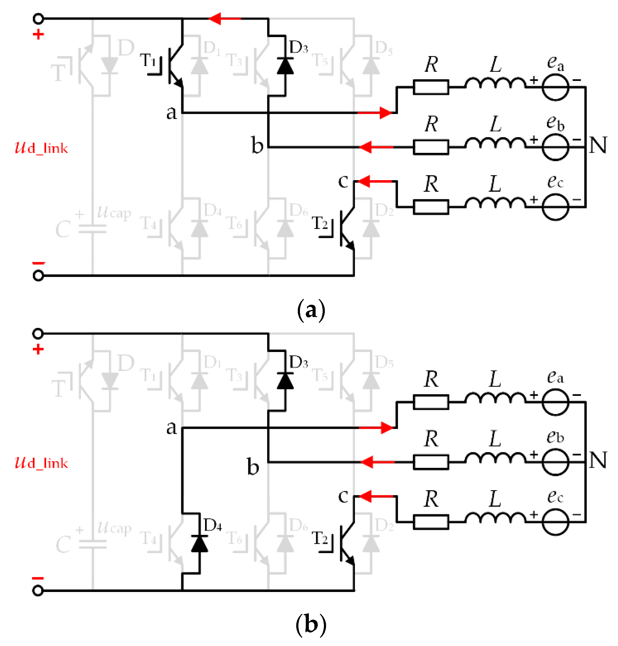
2. The Brushless DC Motor (BLDCM) Drive System with Small DC-Link Capacitor
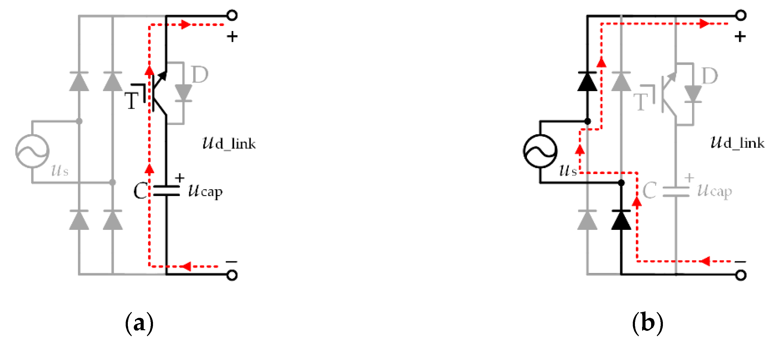
2.1. DC-Link Topology
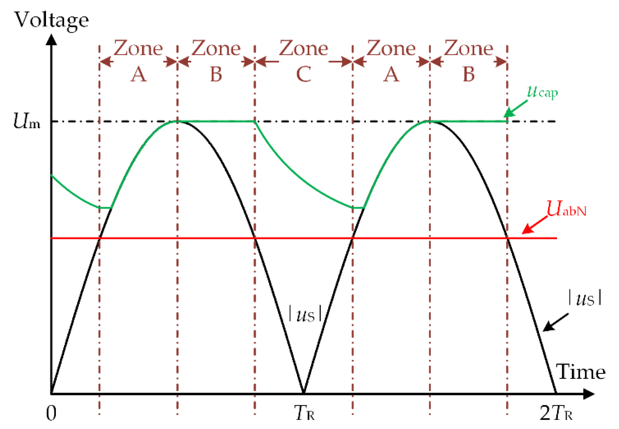
2.2. Operation Principles of BLDCM
- Zone A: |us| ≥ UabN and |us| increase monotonously.
- Zone B: |us| ≥ UabN and |us| decrease monotonously.
- Zone C: |us| < UabN;
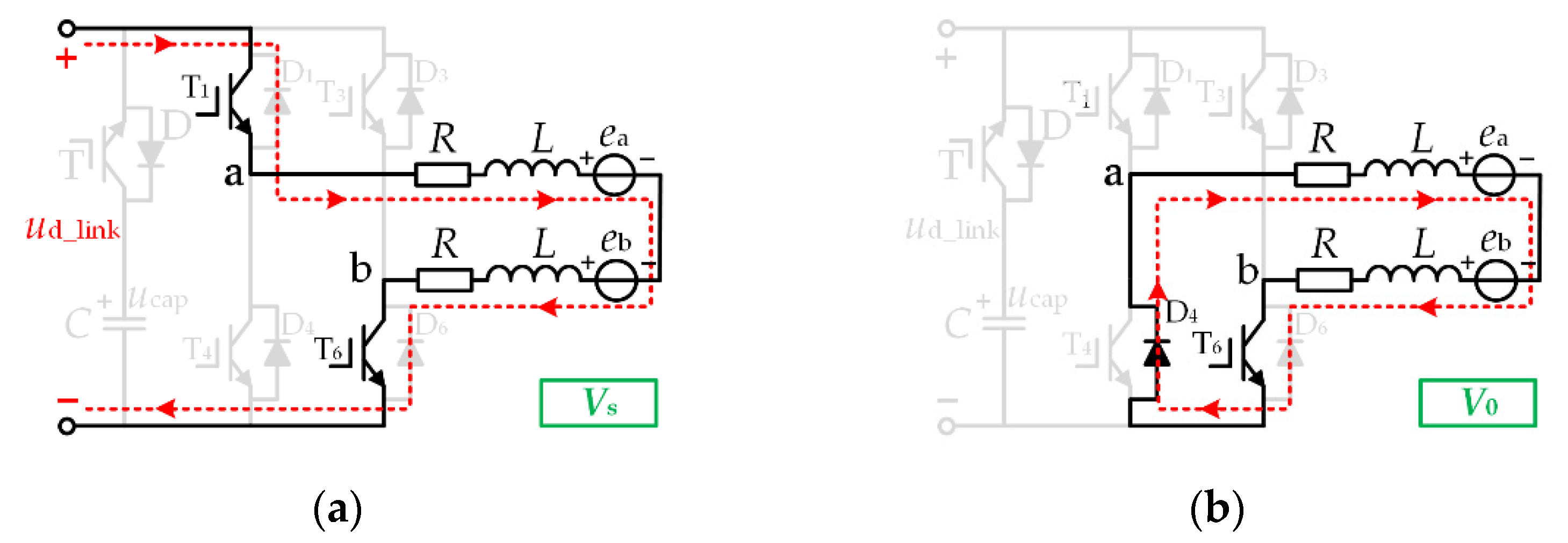
2.3. Control Method during Normal Conduction Period
3. Commutation Torque Ripple Reduction Strategy
3.1. Causes Commutation Torque Ripple
3.2. Commutation Torque Ripple Reduction Strategy
3.3. Controller Design
4. Experimental Results and Analysis
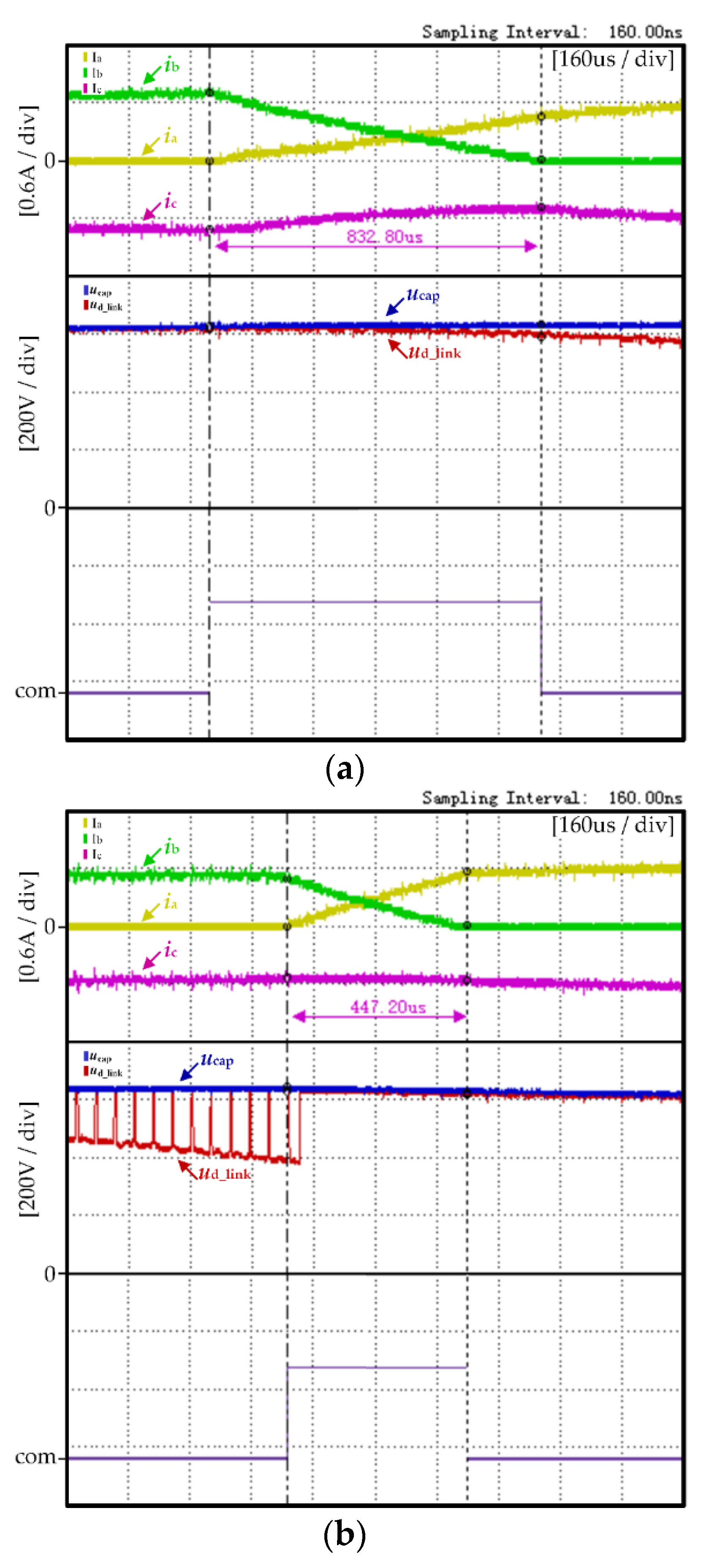
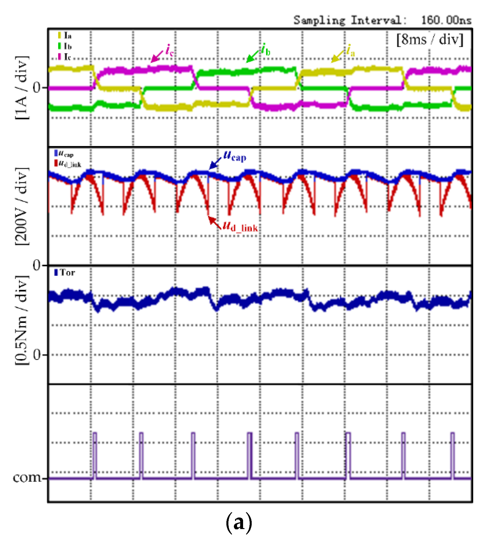
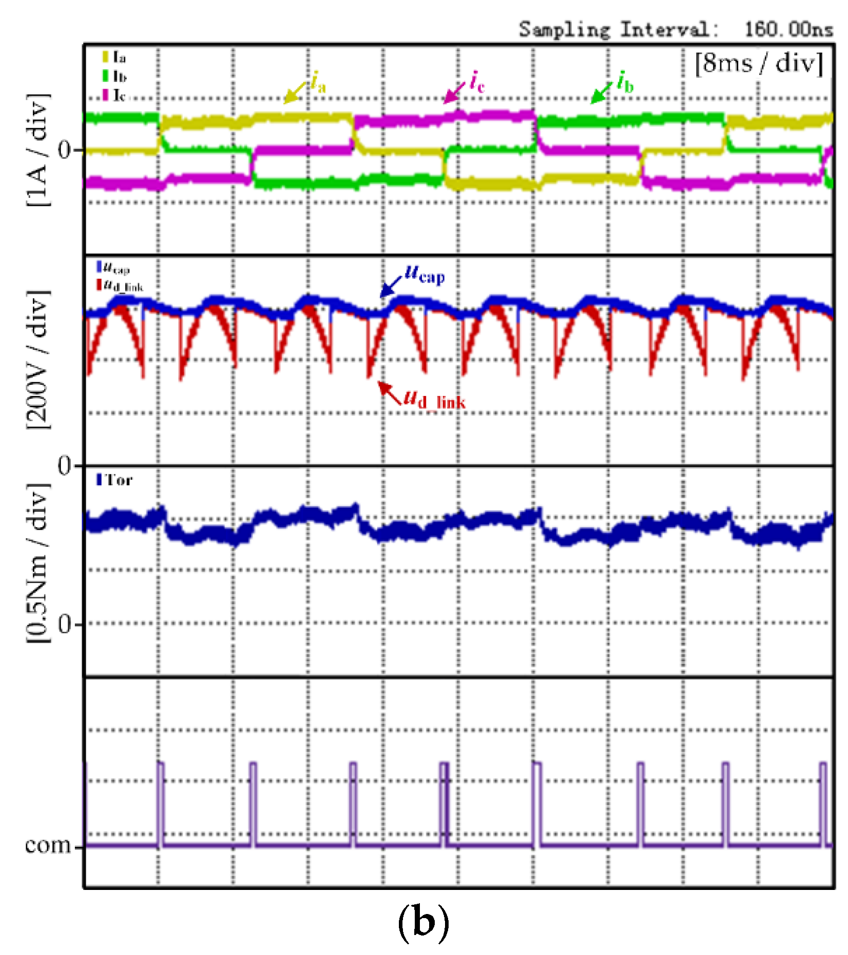
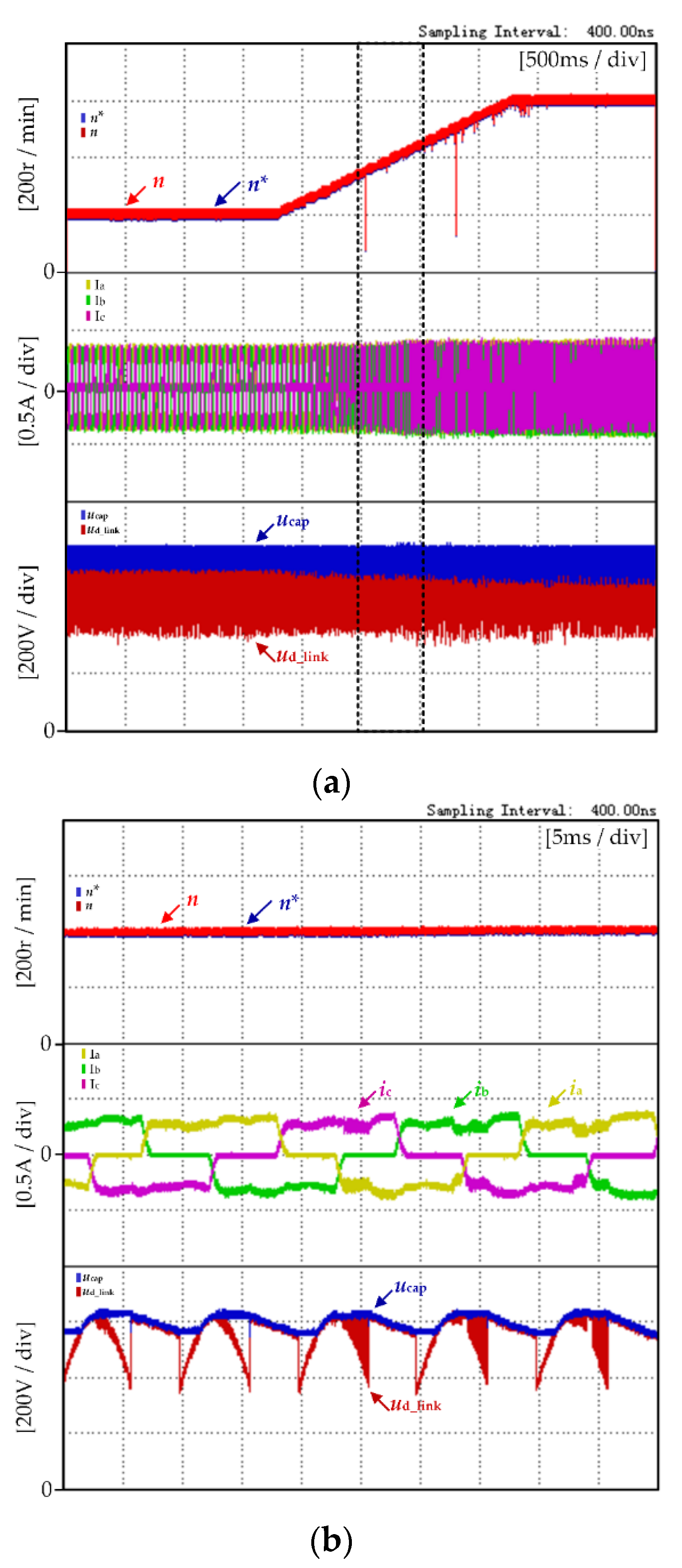
4.1. Experimental Results and Analysis at High Speed
4.2. Experimental Results and Analysis at Low Speed
4.3. Controller Design
5. Conclusions
- (1)
- There is no need to set up an auxiliary boost circuit, and it is completed only by the characteristics of the motor inductance so that the DC-link capacitor can meet the high voltage required during the commutation period of the brushless DC motor.
- (2)
- The proposed strategy in this paper reduces the commutation torque ripple of the motor while maintaining the normal operation of the motor. Compared with traditional methods, the influence of the commutation torque ripple on the operation of the motor as reduced, and the stability of the motor system was improved. The proposed strategy is beneficial to the application of brushless DC motors in the field of high precision and high stability requirements.
Author Contributions
Funding
Conflicts of Interest
References
- Scapini, R.Z.; Bellinaso, L.V.; Michels, L. Stability Analysis of AC–DC Full-Bridge Converters With Reduced DC-Link Capacitance. IEEE Trans. Power Electron. 2018, 33, 899–908. [Google Scholar] [CrossRef]
- Huh, N.; Park, H.; Lee, M.H.; Kim, J. Hybrid PWM Control for Regulating the High-Speed Operation of BLDC Motors and Expanding the Current Sensing Range of DC-link Single-Shunt. Energies 2019, 12, 4347. [Google Scholar] [CrossRef] [Green Version]
- Liu, Y.; Zhao, J.; Xia, M.; Luo, H. Model Reference Adaptive Control-Based Speed Control of Brushless DC Motors With Low-Resolution Hall-Effect Sensors. IEEE Trans. Power Electron. 2014, 29, 1514–1522. [Google Scholar]
- Achary, R.K.; Durgaprasanth, S.; Nagamani, C.; Ilango, G.S. A Simple Voltage Modulator Scheme for Torque Ripple Minimization in a Permanent Magnet Brushless DC Motor. IEEE Trans. Power Electron. 2020, 35, 2809–2818. [Google Scholar] [CrossRef]
- Carlson, R.; Lajoie-Mazenc, M. Analysis of torque ripple due to phase commutation in brushless DC machines. IEEE Trans. Ind. Appl. 1992, 28, 623–638. [Google Scholar] [CrossRef]
- Shchur, I.; Jancarczyk, D. Electromagnetic Torque Ripple in Multiple Three-Phase Brushless DC Motors for Electric Vehicles. Electronics 2021, 10, 3097. [Google Scholar] [CrossRef]
- Cao, Y.; Shi, T.; Niu, X.; Li, X.; Xia, C. A Smooth Torque Control Strategy for Brushless DC Motor in Braking Operation. IEEE Trans. Energy Convers. 2018, 33, 1443–1452. [Google Scholar] [CrossRef]
- Song, J.; Choy, I. Commutation torque ripple reduction in brushless DC motor drives using a single DC current sensor. IEEE Trans. Power Electron. 2004, 19, 312–319. [Google Scholar] [CrossRef]
- Xia, C.; Wang, Y.; Shi, T. Implementation of Finite-State Model Predictive Control for Commutation Torque Ripple Minimization of Permanent-Magnet Brushless DC Motor. IEEE Trans. Ind. Electron. 2013, 60, 896–905. [Google Scholar] [CrossRef]
- Xia, K.; Ye, Y.; Ni, J.; Wang, Y.; Xu, P. Model Predictive Control Method of Torque Ripple Reduction for BLDC Motor. IEEE Trans. Magn. 2020, 56, 1–6. [Google Scholar] [CrossRef]
- Shi, T.; Cao, Y.; Jiang, G.; Li, X.; Xia, C. A Torque Control Strategy for Torque Ripple Reduction of Brushless DC Motor With Nonideal Back Electromotive Force. IEEE Trans. Ind. Electron. 2017, 64, 4423–4433. [Google Scholar] [CrossRef]
- Shi, T.; Guo, Y.; Song, P.; Xia, C. A New Approach of Minimizing Commutation Torque Ripple for Brushless DC Motor Based on DC–DC Converter. IEEE Trans. Ind. Electron. 2010, 57, 3483–3490. [Google Scholar] [CrossRef]
- Li, X.; Xia, C.; Cao, Y.; Chen, W.; Shi, T. Commutation Torque Ripple Reduction Strategy of Z-Source Inverter Fed Brushless DC Motor. IEEE Trans. Power Electron. 2016, 31, 7677–7690. [Google Scholar] [CrossRef]
- Jiang, G.; Xia, C.; Chen, W.; Shi, T.; Li, X.; Cao, Y. Commutation Torque Ripple Suppression Strategy for Brushless DC Motors With a Novel Noninductive Boost Front End. IEEE Trans. Power Electron. 2018, 33, 4274–4284. [Google Scholar] [CrossRef]
- Vogelsberger, M.A.; Wiesinger, T.; Ertl, H. Life-Cycle Monitoring and Voltage-Managing Unit for DC-Link Electrolytic Capacitors in PWM Converters. IEEE Trans. Power Electron. 2011, 26, 493–503. [Google Scholar] [CrossRef]
- Jung, H.; Chee, S.; Sul, S.; Park, Y.; Park, H.; Kim, W. Control of Three-Phase Inverter for AC Motor Drive With Small DC-Link Capacitor Fed by Single-Phase AC Source. IEEE Trans. Ind. Appl. 2014, 50, 1074–1081. [Google Scholar] [CrossRef]
- Samitha Ransara, H.K.; Madawala, U.K. A Torque Ripple Compensation Technique for a Low-Cost Brushless DC Motor Drive. IEEE Trans. Ind. Electron. 2015, 62, 6171–6182. [Google Scholar] [CrossRef]
- Maharajan, M.P.; Xavier, S.A.E. Design of Speed Control and Reduction of Torque Ripple Factor in BLdc Motor Using Spider Based Controller. IEEE Trans. Power Electron. 2019, 34, 7826–7837. [Google Scholar] [CrossRef]


| Zone | State of T | State of T1 | State of T6 |
|---|---|---|---|
| A | OFF | dA | ON |
| B | OFF | dB | ON |
| C | ON | dC | ON |
| Parameter | Symbol | Value | |
|---|---|---|---|
| BLDCM | Rated current | IN | 0.6 A |
| Rated back EMF | EN | 65.5 V | |
| Phase resistance | R | 44.9 Ω | |
| Phase inductance | L | 120 mH | |
| Back EMF coefficient | Ke | 0.7825 V/(rad/s) | |
| Rated load | TN | 0.89 N·m | |
| Rated speed | nN | 800 r/min | |
| Poles pairs | P | 5 | |
| Main Supply | Mains supply voltage | Us | 220 Vrms |
| Mains supply frequency | f | 50 Hz |
Publisher’s Note: MDPI stays neutral with regard to jurisdictional claims in published maps and institutional affiliations. |
© 2022 by the authors. Licensee MDPI, Basel, Switzerland. This article is an open access article distributed under the terms and conditions of the Creative Commons Attribution (CC BY) license (https://creativecommons.org/licenses/by/4.0/).
Share and Cite
Li, X.; Yuan, H.; Chen, W.; Yu, L.; Gu, X. Commutation Torque Ripple Reduction Strategy of Brushless DC Motor Drives Based on Boosting Voltage of DC-Link Small Capacitor. Micromachines 2022, 13, 226. https://doi.org/10.3390/mi13020226
Li X, Yuan H, Chen W, Yu L, Gu X. Commutation Torque Ripple Reduction Strategy of Brushless DC Motor Drives Based on Boosting Voltage of DC-Link Small Capacitor. Micromachines. 2022; 13(2):226. https://doi.org/10.3390/mi13020226
Chicago/Turabian StyleLi, Xinmin, He Yuan, Wei Chen, Lihong Yu, and Xin Gu. 2022. "Commutation Torque Ripple Reduction Strategy of Brushless DC Motor Drives Based on Boosting Voltage of DC-Link Small Capacitor" Micromachines 13, no. 2: 226. https://doi.org/10.3390/mi13020226
APA StyleLi, X., Yuan, H., Chen, W., Yu, L., & Gu, X. (2022). Commutation Torque Ripple Reduction Strategy of Brushless DC Motor Drives Based on Boosting Voltage of DC-Link Small Capacitor. Micromachines, 13(2), 226. https://doi.org/10.3390/mi13020226