
A Narrow Straight Microchannel Array for Analysis of Transiting Speed of Floating Cancer Cells


Abstract
:1. Introduction
2. Materials and Methods
2.1. Device Fabrication
2.2. Simulation
2.3. Cell Culture
2.4. Image Capture
2.5. Data Processing
3. Results
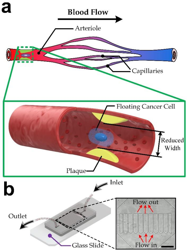
3.1. Device Design
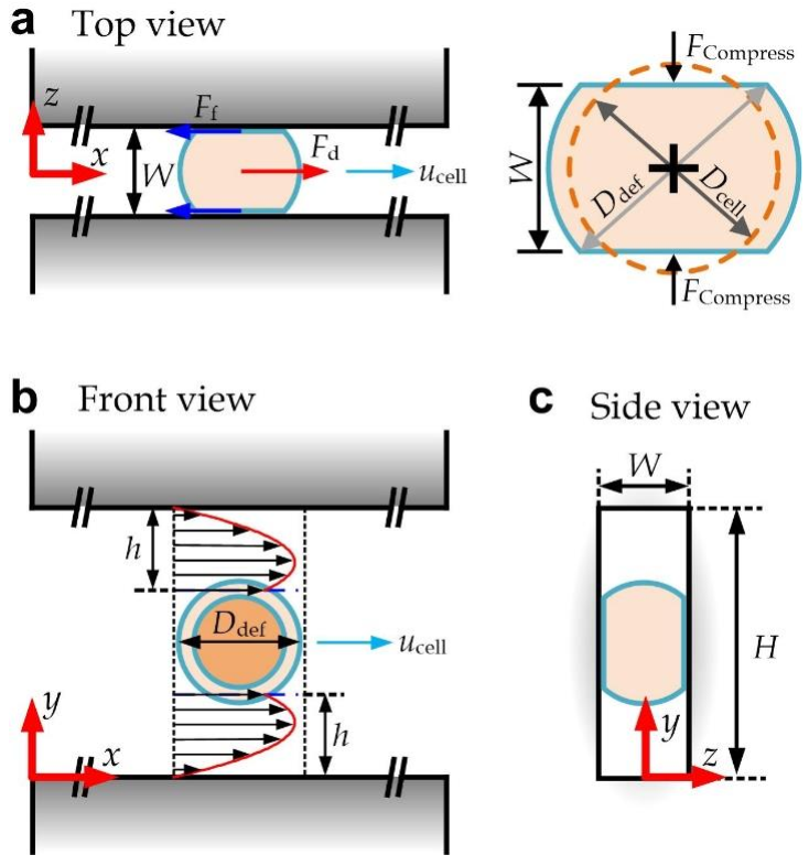
3.2. Modeling of a Deformed Cell Transiting along a Straight Channel
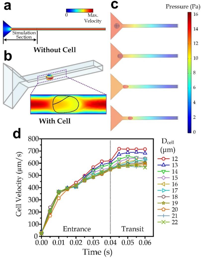
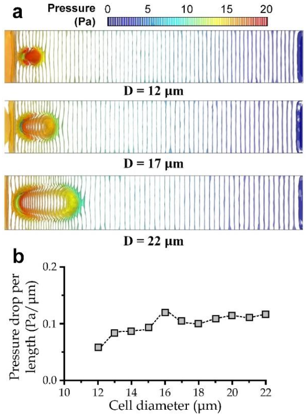
3.3. Simulation for the Cell Transiting Speed
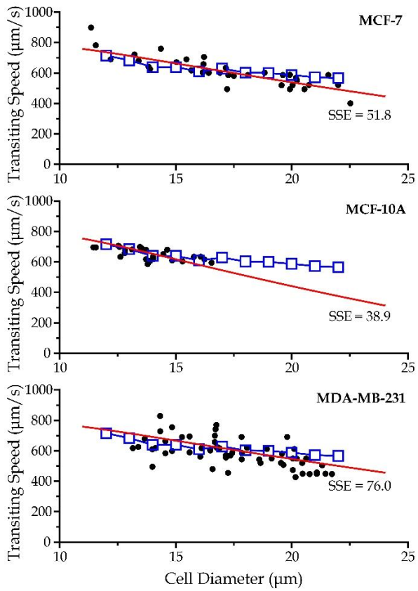
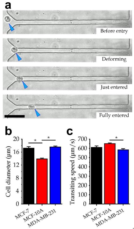
3.4. Experiment Verification
4. Discussion
Author Contributions
Funding
Conflicts of Interest
References
- Cao, H.; Xu, E.; Liu, H.; Wan, L.; Lai, M. Epithelial–mesenchymal transition in colorectal cancer metastasis: A system review. Pathol.-Res. Pract. 2015, 211, 557–569. [Google Scholar] [CrossRef] [PubMed]
- Yeung, T.L.; Leung, C.S.; Yip, K.P.; Yeung, C.L.A.; Wong, S.T.; Mok, S.C. Cellular and molecular processes in ovarian cancer metastasis. A Review in the Theme: Cell and Molecular Processes in Cancer Metastasis. Am. J. Physiol.-Cell Physiol. 2015, 309, C444–C456. [Google Scholar] [CrossRef] [PubMed] [Green Version]
- Rothwell, P.M.; Wilson, M.; Price, J.F.; Belch, J.F.; Meade, T.W.; Mehta, Z. Effect of daily aspirin on risk of cancer metastasis: A study of incident cancers during randomised controlled trials. Lancet 2012, 379, 1591–1601. [Google Scholar] [CrossRef]
- Gupta, G.P.; Massagué, J. Cancer metastasis: Building a framework. Cell 2006, 127, 679–695. [Google Scholar] [CrossRef] [Green Version]
- Pantel, K.; Speicher, M.R. The biology of circulating tumor cells. Oncogene 2016, 35, 1216–1224. [Google Scholar] [CrossRef]
- Pore, M.; Meijer, C.; de Bock, G.H.; Boersma-van Ek, W.; Terstappen, L.W.; Groen, H.J.; Timens, W.; Kruyt, F.A.; Hiltermann, T.J.N. Cancer stem cells, epithelial to mesenchymal markers, and circulating tumor cells in small cell lung cancer. Clin. Lung Cancer 2016, 17, 535–542. [Google Scholar] [CrossRef]
- Giuliano, M.; Giordano, A.; Jackson, S.; Hess, K.R.; De Giorgi, U.; Mego, M.; Handy, B.C.; Ueno, N.T.; Alvarez, R.H.; De Laurentiis, M.; et al. Circulating tumor cells as prognostic and predictive markers in metastatic breast cancer patients receiving first-line systemic treatment. Breast Cancer Res. 2011, 13, R67. [Google Scholar] [CrossRef] [Green Version]
- Scher, H.I.; Jia, X.; de Bono, J.S.; Fleisher, M.; Pienta, K.J.; Raghavan, D.; Heller, G. Circulating tumour cells as prognostic markers in progressive, castration-resistant prostate cancer: A reanalysis of IMMC38 trial data. Lancet Oncol. 2009, 10, 233–239. [Google Scholar] [CrossRef] [Green Version]
- Hakim, M.; Khorasheh, F.; Alemzadeh, I.; Vossoughi, M. A new insight to deformability correlation of circulating tumor cells with metastatic behavior by application of a new deformability-based microfluidic chip. Anal. Chim. Acta 2021, 1186, 339115. [Google Scholar] [CrossRef]
- Au, S.H.; Storey, B.D.; Moore, J.C.; Tang, Q.; Chen, Y.L.; Javaid, S.; Sarioglu, A.F.; Sullivan, R.; Madden, M.W.; O’Keefe, R.; et al. Clusters of circulating tumor cells traverse capillary-sized vessels. Proc. Natl. Acad. Sci. USA 2016, 113, 4947–4952. [Google Scholar] [CrossRef] [Green Version]
- Sasportas, L.S.; Gambhir, S.S. Imaging circulating tumor cells in freely moving awake small animals using a miniaturized intravital microscope. PLoS ONE 2014, 9, e86759. [Google Scholar] [CrossRef] [PubMed]
- Freitas, V.M.; Hilfenhaus, G.; Iruela-Arispe, M.L. Metastasis of circulating tumor cells: Speed matters. Dev. Cell 2018, 45, 3–5. [Google Scholar] [CrossRef] [PubMed] [Green Version]
- Hou, H.W.; Li, Q.S.; Lee, G.Y.H.; Kumar, A.P.; Ong, C.N.; Lim, C.T. Deformability study of breast cancer cells using microfluidics. Biomed. Microdevices 2009, 11, 557–564. [Google Scholar] [CrossRef] [PubMed]
- Leong, F.Y.; Li, Q.; Lim, C.T.; Chiam, K.H. Modeling cell entry into a micro-channel. Biomech. Model. Mechanobiol. 2011, 10, 755–766. [Google Scholar] [CrossRef]
- Byun, S.; Son, S.; Amodei, D.; Cermak, N.; Shaw, J.; Kang, J.H.; Hecht, V.C.; Winslow, M.M.; Jacks, T.; Mallick, P.; et al. Characterizing deformability and surface friction of cancer cells. Proc. Natl. Acad. Sci. USA 2013, 110, 7580–7585. [Google Scholar] [CrossRef] [Green Version]
- Juratli, M.A.; Sarimollaoglu, M.; Siegel, E.R.; Nedosekin, D.A.; Galanzha, E.I.; Suen, J.Y.; Zharov, V.P. Real-time monitoring of circulating tumor cell release during tumor manipulation using in vivo photoacoustic and fluorescent flow cytometry. Head Neck 2014, 36, 1207–1215. [Google Scholar] [CrossRef]
- Ye, T.; Shi, H.; Phan-Thien, N.; Lim, C.T.; Li, Y. Numerical design of a microfluidic chip for probing mechanical properties of cells. J. Biomech. 2019, 84, 103–112. [Google Scholar] [CrossRef]
- Qiang, Y.; Liu, J.; Dao, M.; Suresh, S.; Du, E. Mechanical fatigue of human red blood cells. Proc. Natl. Acad. Sci. USA 2019, 116, 19828–19834. [Google Scholar] [CrossRef] [Green Version]
- Zhang, Z.; Xu, J.; Hong, B.; Chen, X. The effects of 3D channel geometry on CTC passing pressure–towards deformability-based cancer cell separation. Lab Chip 2014, 14, 2576–2584. [Google Scholar] [CrossRef]
- Zhang, Z.; Xu, J.; Chen, X. Predictive model for the cell passing pressure in deformation-based CTC chips. In ASME 2014 International Mechanical Engineering Congress and Exposition; American Society of Mechanical Engineers Digital Collection; American Society of Mechanical Engineers: New York, NY, USA, 2014. [Google Scholar]
- Zheng, X.; Yazdani, A.; Li, H.; Humphrey, J.D.; Karniadakis, G.E. A three-dimensional phase-field model for multiscale modeling of thrombus biomechanics in blood vessels. PLoS Comput. Biol. 2020, 16, e1007709. [Google Scholar] [CrossRef] [PubMed]
- Zhang, X.; Zheng, L.; Luo, M.; Shu, C.; Wang, E. Evaluation of particle shape, size and magnetic field intensity for targeted delivery efficiency and plaque injury in treating atherosclerosis. Powder Technol. 2020, 366, 63–72. [Google Scholar] [CrossRef]
- Hong, B.; Zu, Y. Detecting circulating tumor cells: Current challenges and new trends. Theranostics 2013, 3, 377. [Google Scholar] [CrossRef] [PubMed] [Green Version]
- Hu, S.; Wang, R.; Tsang, C.M.; Tsao, S.W.; Sun, D.; Lam, R.H. Revealing elasticity of largely deformed cells flowing along confining microchannels. RSC Adv. 2018, 8, 1030–1038. [Google Scholar] [CrossRef] [Green Version]
- Milovanovic, L.; Ma, H. Method for measurement of friction forces on single cells in microfluidic devices. Anal. Methods 2012, 4, 4303–4309. [Google Scholar] [CrossRef]
- Metwally, M.K.; El-Gohary, S.H.; Han, S.M.; Byun, K.M.; Kim, T.S. Influence of the anisotropic mechanical properties of the breast cancer on photoacoustic imaging. In Proceedings of the 2014 Cairo International Biomedical Engineering Conference (CIBEC), Giza, Egypt, 11–13 December 2014. [Google Scholar]
- Li, Y.; Li, Y.; Zhang, Q.; Wang, L.; Guo, M.; Wu, X.; Guo, Y.; Chen, J.; Chen, W. Mechanical properties of chondrocytes estimated from different models of micropipette aspiration. Biophys. J. 2019, 116, 2181–2194. [Google Scholar] [CrossRef] [PubMed]
- Quan, F.-S.; Kim, K.S. Medical applications of the intrinsic mechanical properties of single cells. Acta Biochim. Biophys. Sin. 2016, 48, 865–871. [Google Scholar] [CrossRef] [Green Version]
- Smolyakov, G.; Thiebot, B.; Campillo, C.; Labdi, S.; Severac, C.; Pelta, J.; Dague, E. Elasticity, adhesion, and tether extrusion on breast cancer cells provide a signature of their invasive potential. ACS Appl. Mater. Interfaces 2016, 8, 27426–27431. [Google Scholar] [CrossRef] [Green Version]
- Kalwarczyk, T.; Ziebacz, N.; Bielejewska, A.; Zaboklicka, E.; Koynov, K.; Szymanski, J.; Wilk, A.; Patkowski, A.; Gapinski, J.; Butt, H.J.; et al. Comparative analysis of viscosity of complex liquids and cytoplasm of mammalian cells at the nanoscale. Nano Lett. 2011, 11, 2157–2163. [Google Scholar] [CrossRef]
- Diz-Muñoz, A.; Fletcher, D.A.; Weiner, O.D. Use the force: Membrane tension as an organizer of cell shape and motility. Trends Cell Biol. 2013, 23, 47–53. [Google Scholar] [CrossRef] [Green Version]
- Gensbittel, V.; Kräter, M.; Harlepp, S.; Busnelli, I.; Guck, J.; Goetz, J.G. Mechanical adaptability of tumor cells in metastasis. Dev. Cell 2021, 56, 164–179. [Google Scholar] [CrossRef]
- Zhu, X.; Suo, Y.; Fu, Y.; Zhang, F.; Ding, N.; Pang, K.; Xie, C.; Weng, X.; Tian, M.; He, H.; et al. In vivo flow cytometry reveals a circadian rhythm of circulating tumor cells. Light Sci. Appl. 2021, 10, 110. [Google Scholar] [CrossRef] [PubMed]


Publisher’s Note: MDPI stays neutral with regard to jurisdictional claims in published maps and institutional affiliations. |
© 2022 by the authors. Licensee MDPI, Basel, Switzerland. This article is an open access article distributed under the terms and conditions of the Creative Commons Attribution (CC BY) license (https://creativecommons.org/licenses/by/4.0/).
Share and Cite
Ren, J.; Liu, Y.; Huang, W.; Lam, R.H.W. A Narrow Straight Microchannel Array for Analysis of Transiting Speed of Floating Cancer Cells. Micromachines 2022, 13, 183. https://doi.org/10.3390/mi13020183
Ren J, Liu Y, Huang W, Lam RHW. A Narrow Straight Microchannel Array for Analysis of Transiting Speed of Floating Cancer Cells. Micromachines. 2022; 13(2):183. https://doi.org/10.3390/mi13020183
Chicago/Turabian StyleRen, Jifeng, Yi Liu, Wei Huang, and Raymond H. W. Lam. 2022. "A Narrow Straight Microchannel Array for Analysis of Transiting Speed of Floating Cancer Cells" Micromachines 13, no. 2: 183. https://doi.org/10.3390/mi13020183
APA StyleRen, J., Liu, Y., Huang, W., & Lam, R. H. W. (2022). A Narrow Straight Microchannel Array for Analysis of Transiting Speed of Floating Cancer Cells. Micromachines, 13(2), 183. https://doi.org/10.3390/mi13020183