Article

Thermal–Hydrodynamic Behavior and Design of a Microchannel Pin-Fin Hybrid Heat Sink

1
College of Power Engineering, Naval University of Engineering, Wuhan 430033, China
2
Institute of Thermal Science and Power Engineering, Wuhan 430205, China
3
School of Mechanical & Electrical Engineering, Wuhan Institute of Technology, Wuhan 430205, China
*
Authors to whom correspondence should be addressed.
Micromachines 2022, 13(12), 2136; https://doi.org/10.3390/mi13122136
Submission received: 9 October 2022 / Revised: 26 November 2022 / Accepted: 28 November 2022 / Published: 2 December 2022
(This article belongs to the Section E:Engineering and Technology)

Abstract

:
A three-dimensional convective heat transfer model of a microchannel pin-fin hybrid heat sink was established. Considering the non-uniform heat generation of 3D stacked chips, the splitting distance of pin-fins was optimized by minimizing the maximum heat sink temperature under different heat fluxes in the hotspot, the Reynolds numbers at the entrance of the microchannel, and the proportions of the pin-fin volume. The average pressure drop and the performance evaluation criteria were considered to be the performance indexes to analyze the influence of each parameter on the flow performance and comprehensive performance, respectively. The results showed that the maximum temperature of the hybrid heat sink attained a minimum value with an increase in the splitting distance. The average pressure drop in the center passage of the microchannel first increased and then decreased. Furthermore, the optimal value could not be simultaneously obtained with the maximum temperature. Therefore, it should be comprehensively considered in the optimization design. The heat flux in the hotspot was positively correlated with the maximum heat sink temperature. However, it had no effect on the flow pressure drop. When the Reynolds number and the pin-fin diameter increased, the maximum heat sink temperature decreased and the average pressure drop of the microchannel increased. The comprehensive performance of the hybrid heat sink was not good at small Reynolds numbers, but it significantly improved as the Reynolds number gradually increased. Choosing a bigger pin-fin diameter and the corresponding optimal value of the splitting distance in a given Reynolds number would further improve the comprehensive performance of a hybrid heat sink.

1. Introduction

Electronic devices are developing toward miniaturization, being lightweight, and having a high integration, promoted by the developments in science and technology. A high-level integration leads to a high-power consumption density per unit volume. The performance of a chip is substantially affected if the large amount of heat generated by the integrated circuit cannot be removed in time. Furthermore, thermal failure may occur in severe cases. The proposed microchannel provides a solution to this problem [1].
The heat generation of chips in practical engineering applications is occasionally non-uniform. This leads to the formation of a “hotspot” in the local areas of chips. Certain studies have shown that the heat flux in a hotspot area can be over eight times the average heat flux in the background area [2]. This easily leads to a great non-uniform temperature distribution in an electronic device, reducing the service life of the system. Accordingly, it is of high practical significance to optimize the design of a hybrid heat sink that integrates multiple areas with different cooling capacities (hereinafter referred to as a “hybrid heat sink”); e.g., the combination of a microchannel heat sink in the background area and a pin-fin heat sink in the hot area. In addition, an in-chip cooling structure that is embedded in a semiconductor can reduce the parasitic thermal resistance and improve the overall heat dissipation effect [3,4]. Therefore, an interlayer microchannel pin-fin hybrid heat sink has a broad application prospect for meeting the challenges from high-power microchip-level thermal management problems.
Scholars worldwide have carried out a substantial amount of research on microchip-level cooling technology [5,6,7,8,9,10,11,12,13]. Ansari et al. [14] proposed a hybrid micro-heat sink for cooling microprocessors with non-uniform heat generation. The temperature inhomogeneity and maximum temperature were chosen as the performance indexes as well as the thermal resistance and pump power. Comparative analyses were performed between these with those of a conventional microchannel heat sink. Wang et al. [15] employed a large eddy simulation to investigate the heat transfer performance and flow characteristics of a rectangular channel with three-row miniature square column vortex generators when the Reynolds number varied from 3745 to 11,235. Ling et al. [16] designed a novel interlaced microchannel. Two sidewalls of the microchannel functioned as the main heat transfer surface. The thermal and hydraulic performance of the interlaced and parallel microchannels was numerically investigated using a full-sized conjugate heat transfer model and then compared with the experimental results. The optimized geometric dimensions of the interlaced microchannel, including the depth, width, and spacing, were obtained. Feng et al. [17] investigated the effects of several fluid flow parameters and double-sided heating power on the performance of a heat sink with embedded microfins by experimental and numerical simulation methods, taking the temperature uniformity as the optimization objective. Cheng et al. [18] investigated the hydrodynamic and thermal characteristics of a slot array in a microchannel based on a three-dimensional numerical simulation, and a comparison with a seamless array was conducted. Ding et al. [19] analyzed the temperature distribution at the bottom of a processor and the flow field distribution inside a microchannel for a 3D-IC sandwich microchannel structure. Xie et al. [20] studied the effects of an inclined angle and arrangement method on the hydraulic and thermal performance of microchannel heat sinks. Chen et al. [21] presented a novel cross-rib microchannel heat sink to induce a fluid to self-rotate and then studied the effects of the aspect ratio of the microchannel. Omri et al. [22] presented a microchannel heat exchanger equipped with triangular fins and applied a CNT–water nanofluid as a coolant. They found that the triangular fins in the heat exchanger could significantly improve the thermal performance of the microchannel heat exchanger and the geometrical parameters of the triangular fins had various effects on the comprehensive performance of the microchannel heat exchanger.
Based on the literature [14,17,18], this study applied split pin-fins to a hybrid heat sink; considered the thermal–hydrodynamic coupling effect of, and the non-uniform heat generation by, the chip; optimized the splitting distance of the pin-fins; and analyzed the influence of the heat flux on the hotspot, the Reynolds number at the entrance of the microchannel, and the volume ratio of the pin-fins on the thermal–hydrodynamic performance of the chip. The results may provide theoretical guidance for the design of a high-power microchip-level thermal management scheme.

2. Models and Solutions

2.1. Geometrical Model

Figure 1 shows a 3D stacked chip with a microchannel interlayer cooling system. As shown in the figure, each chip layer had an independent microchannel interlayer cooling the heat sink. The microchannels and pin-fins arrays were embedded to enhance the heat dissipation effect. Each chip was connected by thermal interface material (TIM) and a micropump. The TSV integrated in the microchannel sidewall and pin-fin arrays enabled an electrical and communication interconnection between the different chips. The silicon substrate was the base that supported the entire 3D stacked chip and acted as a fluid inlet and outlet. The liquid coolant was pumped through a micropump into the fluid inlet. It then flowed through the hybrid heat sink and finally into the fluid outlet. As shown in Figure 1 [11], each chip layer had a device layer that generated heat and transferred it to the embedded hybrid heat sink. Thus, an individual hybrid heat sink (see Figure 2a [9]) was heated on both sides. To simplify the model and reduce the computational cost, an individual hybrid heat sink was selected for an optimization design and the boundary conditions of the double-sided heat flow were specified. In addition, the heat flux on both sides of the hybrid heat sink was non-uniformly distributed to account for the non-uniform heat generation of the chip. The heated area was divided into the hot area and the background area. The heat flux in the hot area was significantly higher than that in the background area.
The heat sink was integrated with 20 microchannels and 25 pin-fins, which were mainly divided into two areas. The part around the heat sink was the background area of the low heat flux cooled by the microchannels. The red part in the center was the hot area of the high heat flux cooled by the pin-fin array. The values of the geometric parameters of the model are presented in Table 1.
A heat sink was used for the interlayer cooling of the chip. The upper and lower surfaces were heated equally and the remaining outer surface was insulated. In this example, the heat flux in the background area was qbg = 50 W·cm−2, the heat flux in the hot area was qhs = 400–600 W·cm−2, and the Reynolds number at the entrance of the microchannel was Re = 100–300. The proportion of the pin-fin volume was controlled by the pin-fin diameter, which was Dfin = 100–260 μm in this example. As the structure and boundary conditions of the model were horizontally symmetrical, only half of the model was developed and calculated for simplification (see Figure 2b). Figure 3 and Figure 4 show a hotspot model diagram and a cross-sectional diagram of the split pin-fins used in this study, respectively.

2.2. Physical Model

The material of the microchannel pin-fin hybrid heat sink was silicon (constant pressure specific heat capacity cp,s = 700 J·kg−1·k−1, density ρs = 2329 kg·m−3, and thermal conductivity ks = 130 W·m−1·k−1). The cooling medium was deionized water with constant physical parameters. The cooling medium flowed in from one end of the heat sink and flowed out from the other end after a convective heat transfer with the high-temperature wall and high-temperature fins. The Reynolds number at the inlet was set to R e = U in D h / v = 100~300, in which Uin (m·s−1) was the inlet velocity of the deionized water, D h = 2 W ch H ch / W ch + H ch (m) was the hydraulic diameter of the microchannel, and ν (m2·s−1) was the kinematic viscosity of the deionized water. The pressure boundary condition at the exit was pout = 1 atm pressure. The upper and lower surfaces of the rectangular heat sink were heated equally and the remaining outer surface was insulated. In this example, the heat flux from the background area was qbg = 50 W·cm−2 and the heat flux from the hotspot area was qhs = 400~600 W·cm−2. At the fluid–solid interface, there was no slip in the fluid velocity (i.e., U = 0) and the temperature was seen as continuous (i.e., Ts= Tw and q = λ s T s / n = λ f T f / n ). The other external surfaces were adiabatic surfaces (i.e., T / n = 0 ).
The heat flux in the background area and hotspot area was uniform:
q = k s T s
The continuity equation, momentum equation, and energy equation of the fluid laminar flow were:
ρ U = 0
ρ U U = p I + μ U + U T 2 3 μ U I + F
ρ c p U · T + q = Q
where ρ (kg·m−3) is the density, U (m·s−1) is the velocity vector, p (Pa) is the pressure, I is the identity matrix, F(N) is the volume force vector, q (W·m−2) is the heat flux vector, Q (W·m−2) is the heat source term (including the viscous dissipation and pressure work), and T denotes the matrix transpose operation.

2.3. Numerical Methods and Grid Tests

In this study, the finite element calculation software COMSOL Multiphysics was used to solve the thermal–hydrodynamic-coupled model; the flow viscous dissipation was considered whereas the gravitational force and radiation were neglected. The unstructured tetrahedral mesh was divided into fluid and solid areas; the denser boundary layer mesh was divided into areas near the fluid–solid interfaces. The independence of the grid was tested to ensure the calculation accuracy. Considering qhs = 500 W·cm−2, Re = 200, Dfin = 180 μm, and Lfin = 100 μm as an example, the number of grids under the three partitioning strategies of coarsening, conventional, and refinement were 276,205, 873,442, and 2,965,967, respectively. The corresponding Tmax was 365.93 K, 368.96 K, and 371.31 K, and the relative errors were 0.828% and 0.637%, respectively. A second mesh division strategy was adopted in this study to consider the calculation accuracy and efficiency. Figure 5 shows the schematic diagram of the meshes generated in the microchannel pin-fin hybrid heat sink, where the hotspot area was partially enlarged. The common default convergence criterion was used for the continuity, momentum, and energy equations.
To further verify the accuracy of the algorithm in this study, the modeling method in this study was used to establish the microchannel pin-fin hybrid heat sink and heat dissipation model developed in [14] and its calculation was carried out. When the other conditions were fixed, the parameter relationship between the maximum pressure drop of the cooling channels and the Reynolds number was obtained, as shown in Figure 6. As is evident from the numerical comparison, the deviations between the maximum pressure drop of the cooling channel in [14] and the simulation model in this study were negligible at 9 Reynolds numbers.

3. Results and Discussion

3.1. Thermal Behavior and Optimization

(1)
With different heat fluxes at the hotspot
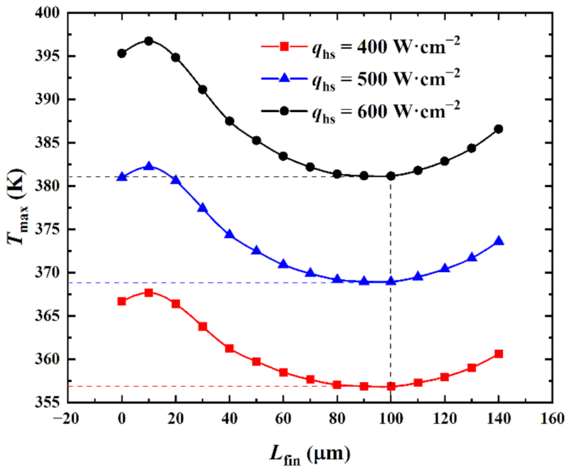
Figure 7 shows the influence of the heat flux qhs in the hotspot on the relationship between the maximum temperature Tmax and the splitting distance Lfin when the inlet Reynolds number was Re = 200 and the pin-fin diameter was Dfin = 180 μm.
Figure 7 shows that when qhs was specified and as Lfin increased, Tmax first marginally increased, then substantially decreased, and finally increased again. The fluid flow rate in the interlayer of the split pin-fins was highly marginal when Lfin was marginal. This was due to the influence of the boundary layer. At this time, the main heat transfer mode was heat conduction and the convective heat transfer made a limited contribution to the heat dissipation effect. Simultaneously, the vertical streamline length of the pin-fins increased, the flow stagnation area of the back flow side of the pin-fins increased, and the heat dissipation performance decreased. Thus, Tmax increased with the increase in Lfin. As Lfin continued to increase, the flow rate of the fluid flowing through the interlayer of the pin-fins gradually increased and the main heat transfer mode became a convective heat transfer. The heat transfer performance of the pin-fins was enhanced and Tmax decreased accordingly. When Lfin > 100 μm, the fluid flow on both sides of the pin-fins and the heat dissipation performance on both sides of the surface continued to decrease with the increase in Lfin. This caused Tmax to gradually increase.
A comparison of the relationship curves between Tmax and Lfin at different qhs revealed that the curves for qhs = 400 W•cm−2, 500 W•cm−2, and 600 W•cm−2 had a similar variation trend. Here, the curves first marginally increased, then substantially decreased, and finally increased again. Tmax minima were obtained at (Lfin)opt = 100 μm for the three curves under different qhs conditions. This indicated that qhs had no effect on the thermal behavior of the element body. The extreme values of Tmax for the three curves increased with the increase in qhs (i.e., 356.85 K, 368.96 K, and 381.16 K, respectively) with increments of 12.11 K and 12.20 K, respectively. It was observed that when qhs increased, Tmax proportionally increased; these were positively correlated. This was because the increase in qhs increased the heat output of the chip and the heat dissipation load of the heat sink. If the generated heat was not emitted in time, Tmax accordingly increased until a thermal balance was attained. (Tmax)min under different qhs was reduced by 9.84 K, 12.04 K, and 14.16 K, respectively, compared with Tmax = 366.69 K, 381.00 K, and 395.32 K under Lfin = 0 μm (reduction of 2.68%, 3.16%, and 3.58%, respectively). That is, the larger the value of qhs, the more significant the effect of Lfin on Tmax. This implied that the higher the heat flux of the 3D stacked chip, the more significant the optimization effect of varying the needle rib splitting distance on the maximum temperature.
(2)
With different Reynolds numbers at the microchannel entrance
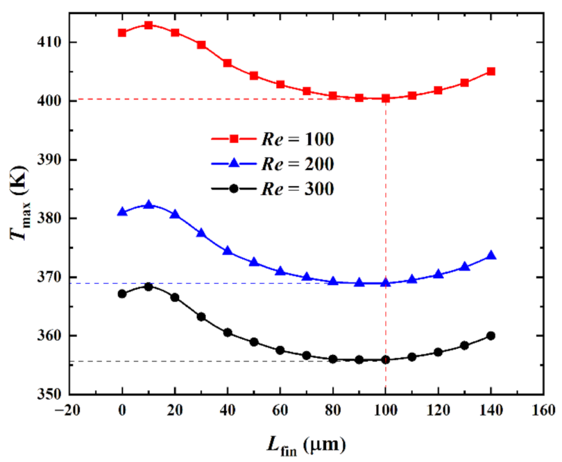
Figure 8 shows the influence of the inlet Reynolds number (Re) on the relationship between the maximum temperature Tmax and the splitting distance Lfin when the heat flux in the hotspot was qhs = 500 W·cm−2 and the pin-fin diameter was Dfin = 180 μm.
Figure 8 shows that when the Re was specified and as Lfin increased, Tmax marginally increased, then decreased, and finally increased again. A comparison between the relationship curves of Tmax and Lfin for different Re revealed that the curves for Re = 100, 200, and 300 had a similar trend. When Re differed, the three curves achieved a Tmax minima at (Lfin)opt = 100 μm with extreme values of 400.46 K, 368.96 K, and 355.93 K, respectively, and incremental values of −31.50 K and −13.03 K, respectively. The overall heat transfer coefficient havg corresponding with these Tmax minima were 30,290 W·m−2·K−1, 35,077 W·m−2·K−1, and 38,432 W·m−2·K−1, respectively. It was observed that for the same model, the fluid flow rate increased and the convective heat transfer effect was enhanced when Re increased. This, in turn, improves the heat dissipation performance of the heat sink and decreased Tmax. The larger the value of Re, the smaller the effect of varying Re on Tmax. That is, an appropriate increase in Re when it was small could reduce Tmax more effectively. (Tmax)min under different Re was reduced by 11.19 K, 12.04 K, and 11.19 K compared with Tmax = 411.65 K, 381.00 K, and 367.12 K, respectively, for Lfin = 0 μm (reduction of 2.72%, 3.16%, and 3.05%, respectively). Therefore, when Tmax was used as a performance metric, variations in Tmax were less affected by Re as Lfin varied.
(3)
With different volume ratios (pin-fin diameters)
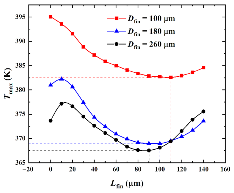
Figure 9 shows the influence of the pin-fin diameter Dfin on the relationship between the maximum temperature Tmax and the splitting distance Lfin when the heat flux in the hotspot was qhs = 500 W·cm−2 and the inlet Reynolds number was Re = 200. Corresponding with Figure 9, 
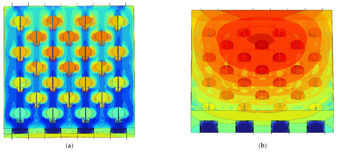
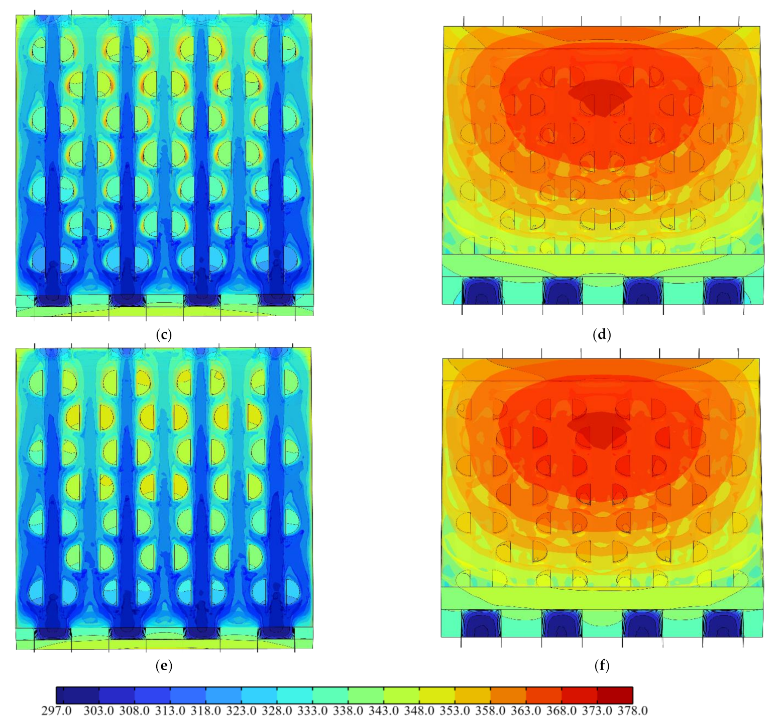
Figure 10 shows the temperature color maps of the hotspot area of the hybrid heat sink when Dfin = 180 μm and Lfin = 10, 100, and 140 μm, respectively.
As can be observed from Figure 9, when Dfin = 180 μm and 260 μm and as Lfin increased, Tmax marginally increased, then decreased, and finally increased. When Dfin = 100 μm and as Lfin increased, Tmax first decreased and then increased. When Dfin = 180 μm and 260 μm, Tmax passed through three stages as Lfin increased. The first stage was where Lfin was small. Here, the main heat transfer mode in the interlayer of the split pin-fins was heat conduction owing to the influence of the small fluid flow rate in the boundary layer. Tmax marginally increased with the increase in Lfin. When Dfin = 180 μm, the Tmax maximum in the first stage was 381.96 K and the corresponding overall heat transfer coefficient havg was 33,612 W·m−2·K−1. In the second stage, Lfin continued to increase, the flow-around effect increased, the disturbance of the fluid flow increased, the convective heat transfer effect increased and became the dominant heat transfer mode, and Tmax accordingly decreased. When Dfin = 180 μm, the Tmax minimum in the second stage was 368.60 K and the corresponding overall heat transfer coefficient havg was 35,067 W·m−2·K−1. The third stage was when Lfin increased to a certain value. With the increase in Lfin, the fluid mainly flowed through the interlayer of the pin-fins and the convective heat transfer effect on the semicircular surface of the pin-fins weakened. This resulted in an increase in Tmax. When Dfin = 180 μm and Lfin = 140 μm, Tmax was 373.23 K and the corresponding overall heat transfer coefficient havg was 34,527 W·m−2·K−1. When Dfin = 100 μm, the obtained data did not reflect the first stage of Tmax because the numerical simulation calculation step (10 μm) was large. These showed a decreasing trend followed by an increasing trend with the increase in Lfin.
When Dfin was 100 μm, 180 μm, and 260 μm, Tmax attained a minimum value when (Lfin)opt = 110 μm, 100 μm, and 90 μm, respectively. The extreme values were 382.57 K, 368.96 K, and 368.13 K, respectively, and the increments were −13.61 K and −0.83 K, respectively. Tmax was reduced by 12.48 K, 12.04 K, and 5.52 K compared with Tmax = 395.05 K, 381.00 K, and 373.65 K, respectively, for Lfin = 0 μm (reduction of 3.15%, 3.16%, and 1.48%, respectively). It was observed that with the increase in Dfin, the surface area of the pin-fin heat transfer and the heat transfer increased. The smaller the value of (Lfin)opt, the less optimal the Tmax that was obtained by varying Lfin. Furthermore, the smaller the value of Dfin, the more significant the effect of varying Dfin and Lfin was on Tmax. This indicated that Dfin and Lfin had optimal matching issues when Tmax was considered to be the performance index. Therefore, in practical engineering applications, the pin-fin diameter can be determined by comprehensively considering the cost, process, and other factors. (Lfin)opt can then be determined according to the relationship curve between Lfin and Tmax so that the heat sink Tmax is minimized and the performance is optimal.

3.2. Hydrodynamic Behavior Analysis

(1)
Influence of the heat flux at the hotspot
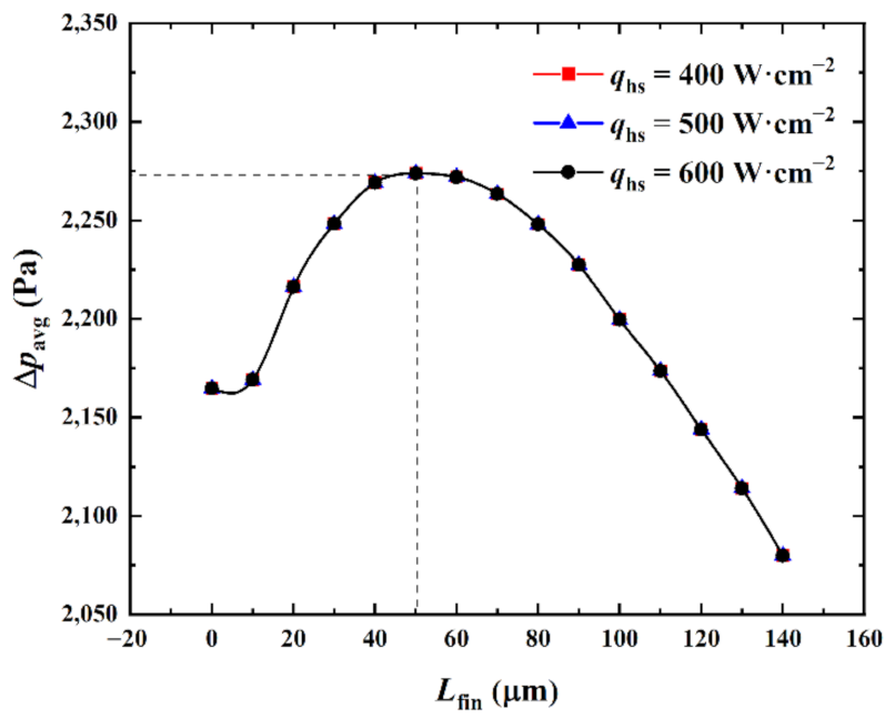
Figure 11 shows the influence of the heat flux qhs at the hotspot on the relationship between the average pressure drop ∆pavg of the center passage and the splitting distance Lfin when the inlet Reynolds number was Re = 200 and the pin-fin diameter Dfin = 180 μm.
As can be observed from Figure 11, when qhs was given and as Lfin increased, ∆pavg marginally increased, then substantially increased, and finally continuously decreased. When Lfin was small, the fluid flow in the interlayer of the split pin-fins was gradual and the disturbance was weak owing to the influence of the boundary layer. However, the increase in the thickness of the split pin-fins in the vertical streamline direction obstructed the fluid flow. This marginally increased the flow resistance and ∆pavg increased with it. When Lfin > 10 μm and continued to increase, the fluid flow in the split pin-fin interlayer gradually increased, so that part of the fluid flowed through the split pin-fin interlayer, the disturbance was enhanced, the flow resistance increased, and ∆pavg greatly increased. When Lfin > 50 μm and with the increase in Lfin, the fluid flow on both sides of the pin-fins gradually decreased, the fluid mainly flowed through the interlayer of the split pin-fins, the disturbance weakened, and ∆pavg continued to decrease.
A comparison of the relationship curves between ∆pavg and Lfin for different qhs revealed that the curves for qhs = 400 W·cm−2, 500 W·cm−2, and 600 W·cm−2 essentially overlapped. Moreover, ∆pavg attained a maximum when (Lfin)opt = 50 μm. A minimum value of 2079.9 Pa was obtained at (Lfin)opt = 140 μm. This was 84.8 Pa lower than ∆pavg = 2164.7 Pa for the cylindrical pin-fins at Lfin = 0 μm (a reduction of 3.92%). It was observed that the variation in qhs essentially had no effect on ∆pavg. This was because the effect of the variation in qhs only altered the temperature field. However, the microchannel retained a single-phase incompressible laminar flow (Re = 200; the fluid was liquid and the physical properties did not vary with the temperature). Thus, the variation in the temperature field at a certain range had no effect on the fluid flow and the flow field and ∆pavg were not affected by qhs. In addition, from the perspective of the fluid flow, increasing the pin-fin splitting distance to the maximum extent within the range permitted by the manufacturing process could be considered. This would reduce the pressure drop in the flow passage and the pump power consumption.
(2)
Influence of the Reynolds number at the microchannel entrance
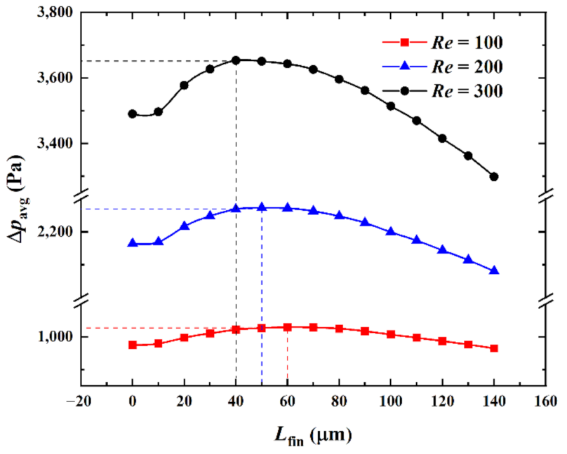
Figure 12 shows the influence of the Reynolds number (Re) at the entrance of the microchannel on the relationship between the average pressure drop ∆pavg in the center passage and the splitting distance Lfin when the heat flux in the hotspot was qhs = 500 W·cm−2 and the pin-fin diameter was Dfin = 180 μm.
As can be observed from Figure 12, when Re was specified and as Lfin increased, ∆pavg marginally increased, then substantially increased, and finally continuously decreased. A comparison of the relationship curves of ∆pavg and Lfin for different Re revealed that the curves for Re = 100, 200, and 300 had a similar variation trend. ∆pavg attained the maximum when (Lfin)opt = 60 μm, 50 μm, and 40 μm and the respective minimums were 964.7 Pa, 2079.9 Pa, and 3298.0 Pa when (Lfin)opt = 140 μm, respectively. The increments were 1115.2 Pa and 1218.1 Pa, which were 9.8 Pa, 84.8 Pa, and 191.8 Pa lower than ∆pavg = 974.5 Pa, 2164.7 Pa, and 3489.8 Pa when Lfin = 0 μm. The reduction percentages were 1.00%, 3.92%, and 5.50%, respectively. It was observed that the flow velocity and flow resistance increased as Re increased and ∆pavg required by the flow accordingly increased. The higher the value of Re, the higher the impact of ∆pavg on the Re variations. That is, the effect of reducing the heat sink ∆pavg by reducing Re was better when Re was small. In addition, when Re was large, the fluid flow rate was large, the disturbance was strong, the fluid was substantially affected by the variation in the pin-fin geometric parameters, Lfin had a more significant effect on ∆pavg, and the optimization space was larger. Therefore, in engineering applications, the higher the value of Re, the higher the significance of the optimal design related to the pin-fin splitting distance.
(3)
Influence of the volume ratio (pin-fin diameter)
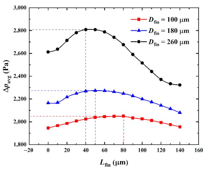
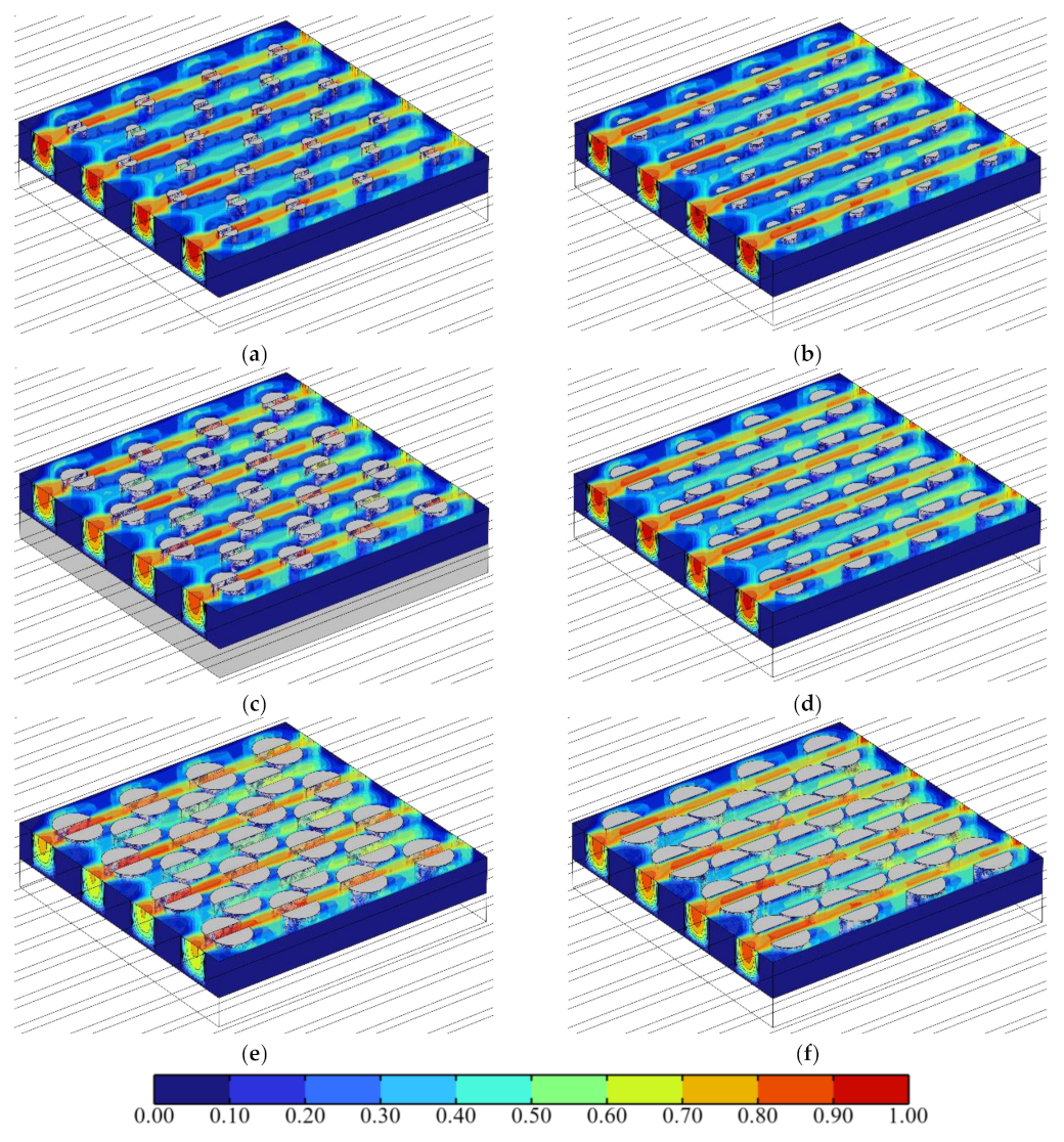
Figure 13 shows the influence of the pin-fin diameter Dfin on the relationship between the average pressure drop ∆pavg in the center passage and the splitting distance Lfin when the heat flux in the hotspot was qhs = 500 W·cm−2 and the inlet Reynolds number was Re = 200. Corresponding with Figure 13, Figure 14 shows the velocity color maps of the hotspot area of the hybrid heat sink when ∆pavg reached the maxima and minima at Dfin = 100, 180, and 260 μm, respectively.
As can be observed from Figure 13, as Lfin increased from 0 μm to 140 μm, the fluid flow in the microchannel underwent a process wherein it mainly flowed through both sides of the pin-fins to the interlayer of the split pin-fins. The fluid disturbance first increased and then weakened. ∆pavg varied with it; increasing first and then continuously decreasing. A comparison between the relationship curves of ∆pavg and Lfin with different Dfin revealed that for Dfin = 100 μm, 180 μm, and 260 μm, ∆pavg attained the maximum value when Lfin = 80 μm, 50 μm, and 40 μm, respectively. Meanwhile, the minimum values were obtained when Lfin = 0 μm, 140 μm, and 140 μm (namely, 1946.1 Pa, 2079.9 Pa, and 2322.7 Pa, respectively, with increments of 133.8 Pa and 242.8 Pa, respectively). Compared with ∆pavg = 1946.1 Pa, 2164.7 Pa, and 2612.4 Pa for Lfin = 0 μm, it was reduced by 0 Pa, 84.8 Pa, and 289.7 Pa, respectively (i.e., by 0%, 3.92%, and 11.09%, respectively). It was observed that the larger the Dfin, the smaller the minimum value of ∆pavg. Furthermore, the larger the decrease with the increase in Dfin, the larger the variation in the influence of Lfin. That is, the larger the Dfin, the higher its influence on ∆pavg. Compared with the cylindrical pin-fin hybrid heat sink when Lfin =0 μm and when ∆pavg was taken as the performance index, the larger the Dfin, the better the optimal performance that could be achieved by tweaking Lfin for the heat sink. In addition, when Dfin = 100 μm, the minimum value of ∆pavg was Lfin = 0 μm. The cylindrical pin-fins then formed the optimal configuration.

3.3. Comprehensive Performance of the Microchannel Pin-Fin Hybrid Heat Sink

From the above thermal and hydrodynamic behavior analysis of the microchannel pin-fin hybrid heat sink, the influences of the flow and structure parameters on the maximum temperature Tmax and the overall heat transfer coefficient havg of the hybrid heat sink were exactly contrary to the average pressure drop ∆pavg of the center passage of the hybrid heat sink. This indicated that it was necessary to further confirm if the comprehensive performance of the microchannel pin-fin hybrid heat sink was better than the conventional microchannel heat sink.
The performance evaluation criteria P E C = ( N u a   /   N u 0 )   /   f a   /   f 0 1 / 3 is a well-known and widely used indicator to describe the comprehensive performance of heat sinks [23]. Nu is the overall Nusselt number, f is the apparent flow friction coefficient, the subscript “0” indicates the conventional microchannel heat sink, and the subscript “a” indicates the microchannel pin-fin hybrid heat sink.
When the heat flux in the hotspot qhs = 500 W·cm−2 and the Reynolds number Re = 100~300, the apparent flow friction coefficients f0 of the conventional microchannel heat sink with the exact dimensions as Table 1 were 0.1652, 0.0871, and 0.0591, respectively; the overall Nusselt numbers Nu0 of the conventional microchannel heat sink were 13.958, 15.674, and 16.842, respectively. The above parameters were used as the benchmark to compare the comprehensive performance of the microchannel pin-fin hybrid heat sink.
Considering the effect of the Reynolds number (Re) and the splitting distance Lfin on the comprehensive performance of the microchannel pin-fin hybrid heat sink (Dfin = 180 μm), PEC = 0.8595 when (Lfin)opt = 100 μm at Re = 100, PEC = 1.2248 when (Lfin)opt = 100 μm at Re = 200, and PEC = 1.5131 when (Lfin)opt = 100 μm at Re = 300, respectively. This indicated that the comprehensive performance of the microchannel pin-fin hybrid heat sink was not good at small Reynolds numbers, but could be significantly improved as the Reynolds number gradually increased.
Considering the effect of the pin-fin diameter Dfin and the splitting distance Lfin on the comprehensive performance of the microchannel pin-fin hybrid heat sink (qhs = 500 W·cm−2; Re = 200), PEC = 1.1607 when (Lfin)opt = 110 μm at Dfin = 100 μm, PEC = 1.2217 when (Lfin)opt = 100 μm at Dfin = 180 μm, and PEC = 1.2312 when (Lfin)opt = 100 μm at Dfin = 180 μm, respectively. This indicated that, at a given Reynolds number, the thermal performance and the comprehensive performance of the microchannel pin-fin hybrid heat sink could be further improved with a bigger pin-fin diameter Dfin and corresponding optimal value of the splitting distance (Lfin)opt.

4. Conclusions

In this study, split pin-fins were applied to a hybrid heat sink and the thermal–hydrodynamic behavior and optimal design of a split pin-fin array at the hotspot was obtained. The influence of the heat flux at the hotspot, the Reynolds number at the entrance of the microchannel, and volume proportion of the pin-fins were analyzed.
The results showed that the maximum temperature of the hybrid heat sink had a minimum value with the increase in the splitting distance of the pin-fins. The average pressure drop in the center passage of the microchannel first increased and then decreased. An optimal value could not be simultaneously obtained with the maximum temperature. Therefore, it should be comprehensively considered in the optimization design. The heat flux in the hotspot was positively correlated with the maximum heat sink temperature. However, it had no effect on the flow pressure drop. The effects of the Reynolds number at the entrance of the microchannel and the volume proportion of the pin-fins were similar. That is, when the Reynolds number and the volume proportion increased, the maximum heat sink temperature decreased whereas the average pressure drop of the microchannel increased and the comprehensive performance of the microchannel pin-fin hybrid heat sink was improved. The larger the value of the Reynolds number and the volume proportion, the smaller the effect.
Based on the concept of a thermal–hydrodynamic coupling optimization design, this study provides a new method and example for the optimization design of a hybrid heat sink with a microchannel and pin-fins. Considering the different processes and structural forms of microchannels and pin-fins, further research to carry out a multi-objective optimization design, including non-uniform heat production and its dynamic characteristics, is worthwhile.

Author Contributions

X.G., conceptualization, data curation, formal analysis, methodology, derivation and calculation, validation, writing—original draft, and software; Z.X., conceptualization, methodology, project administration, supervision, writing—reviewing and editing, and funding acquisition; G.N. and K.X., methodology and visualization; Z.L., visualization and writing—original draft; Y.G., validation and visualization. All authors have read and agreed to the published version of the manuscript.

Funding

This research was funded by the National Natural Science Foundation of China (grant numbers 51979278 and 51579244).

Informed Consent Statement

Not applicable.

Data Availability Statement

Data will be made available on request.

Acknowledgments

The authors wish to thank the reviewers and editors for their careful, unbiased, and constructive suggestions, which led to this revised manuscript.

Conflicts of Interest

The authors declare that they have no known competing financial interests or personal relationships that could have appeared to influence the work reported in this paper.

References

  1. Tuckerman, D.B.; Pease, R.F.W. High-performance heat sinking for VLSI. IEEE Electron. Device Lett. 1981, 2, 126–129. [Google Scholar] [CrossRef]
  2. Sharma, C.S.; Tiwari, M.K.; Zimmermann, S.; Brunschwiler, T.; Schlottig, G.; Michel, B.; Poulikakos, D. Energy efficient hotspot-targeted embedded liquid cooling of electronics. Appl. Energy 2015, 138, 414–422. [Google Scholar] [CrossRef]
  3. Drummond, K.P.; Back, D.; Sinanis, M.D.; Janes, D.B.; Peroulis, D.; Weibel, J.A.; Garimella, S.V. Characterization of hierarchical manifold microchannel heat sink arrays under simultaneous background and hotspot heating conditions. Int. J. Heat Mass Transf. 2018, 126, 1289–1301. [Google Scholar] [CrossRef] [Green Version]
  4. Kong, D.; Jung, K.W.; Jung, S.; Jung, D.; Schaadt, J.; Iyengar, M.; Malone, C.; Kharangate, C.R.; Asheghi, M.; Goodson, K.E.; et al. Single-phase thermal and hydraulic performance of embedded silicon micro-pin fin heat sinks using R245fa. Int. J. Heat Mass Transf. 2019, 141, 145–155. [Google Scholar] [CrossRef]
  5. Ansari, D.; Kim, K.Y. Performance analysis of double-layer microchannel heat sinks under non-uniform heating conditions with random hotspots. Micromachines 2017, 8, 54. [Google Scholar] [CrossRef] [Green Version]
  6. Zając, P.; Maj, C.; Napieralski, A. Peak temperature reduction by optimizing power density distribution in 3D ICs with microchannel cooling. Microelectron. Reliab. 2017, 79, 488–498. [Google Scholar] [CrossRef]
  7. Ghasemi, S.E.; Ranjbar, A.A.; Hosseini, M.J. Experimental and numerical investigation of circular minichannel heat sinks with various hydraulic diameter for electronic cooling application. Microelectron. Reliab. 2017, 73, 97–105. [Google Scholar] [CrossRef]
  8. Zając, P.; Napieralski, A. Novel thermal model of microchannel cooling system designed for fast simulation of liquid-cooled ICs. Microelectron. Reliab. 2018, 87, 245–258. [Google Scholar] [CrossRef]
  9. Soleymani, Z.; Rahimi, M.; Gorzin, M.; Pahamli, Y. Performance analysis of hotspot using geometrical and operational parameters of a microchannel pin-fin hybrid heat sink. Int. J. Heat Mass Transf. 2020, 159, 120141. [Google Scholar] [CrossRef]
  10. Feng, S.; Yan, Y.F.; Li, H.J.; He, Z.Q.; Zhang, L. Temperature uniformity enhancement and flow characteristics of embedded gradient distribution micro pin fin arrays using dielectric coolant for direct intra-chip cooling. Int. J. Heat Mass Transf. 2020, 156, 119675. [Google Scholar] [CrossRef]
  11. Feng, S.; Yan, Y.F.; Li, H.J.; Zhang, L.; Yang, S.L. Thermal management of 3D chip with non-uniform hotspots by integrated gradient distribution annular-cavity micro-pin fins. Appl. Therm. Eng. 2021, 182, 116132. [Google Scholar] [CrossRef]
  12. Nan, G.; Xie, Z.H.; Guan, X.N.; Ji, X.K.; Lin, D.G. Constructal design for the layout of multi-chip module based on thermal-flow-stress coupling calculation. Microelectron. Reliab. 2021, 127, 114417. [Google Scholar] [CrossRef]
  13. Zhang, J.; Xie, Z.H.; Lu, Z.Q.; Li, P.L.; Xi, K. Research on intelligent distribution of liquid flow rate in embedded channels for cooling 3D multi-core chips. Micromachines 2022, 13, 918. [Google Scholar] [CrossRef]
  14. Ansari, D.; Kim, K.Y. Hotspot thermal management using a microchannel-pin fin hybrid heat sink. Int. J. Therm. Sci. 2018, 134, 27–39. [Google Scholar] [CrossRef]
  15. Wang, J.S.; Sun, Z.Y.; Liu, X.L. Heat transfer and flow characteristics in a rectangular channel with miniature square column in aligned and staggered arrangements. Int. J. Therm. Sci. 2020, 155, 106413. [Google Scholar] [CrossRef]
  16. Ling, W.S.; Zhou, W.; Liu, C.Z.; Zhou, F.; Yuan, D.; Huang, J.L. Structure and geometric dimension optimization of interlaced microchannel for heat transfer performance enhancement. Appl. Therm. Eng. 2020, 170, 115011. [Google Scholar] [CrossRef]
  17. Feng, S.; Yan, Y.F.; Li, H.J.; Xu, F.L.; Zhang, L. Heat transfer characteristics investigations on liquid-cooled integrated micro pin-fin chip with gradient distribution arrays and double heating input for intra-chip micro-fluidic cooling. Int. J. Heat Mass Transf. 2020, 159, 120118. [Google Scholar] [CrossRef]
  18. Cheng, X.; Wu, H.Y. Heat transfer and entropy generation analysis of slit pillar array in microchannels. J. Heat Transf. 2020, 142, 092502. [Google Scholar] [CrossRef]
  19. Ding, B.; Zhang, Z.H.; Gong, L.; Xu, M.H.; Huang, Z.Q. A novel thermal management scheme for 3D-IC chips with multi-cores and high power density. Appl. Therm. Eng. 2020, 168, 114832. [Google Scholar] [CrossRef]
  20. Xie, G.F.; Zhao, L.; Dong, Y.Y.; Li, Y.G.; Zhang, S.L.; Yang, C. Hydraulic and thermal performance of microchannel heat sink inserted with pin fins. Micromachines 2021, 12, 245. [Google Scholar] [CrossRef]
  21. Chen, H.Y.; Chen, C.; Zhou, Y.Y.; Yang, C.L.; Song, G.; Hou, F.Z.; Jiao, B.B.; Liu, R.W. Evaluation and optimization of a cross-rib micro-channel heat sink. Micromachines 2022, 13, 132. [Google Scholar] [CrossRef] [PubMed]
  22. Omri, M.; Smaoui, H.; Frechette, L.; Kolsi, L. A new microchannel heat exchanger configuration using CNT-nanofluid and allowing uniform temperature on the active wall. Case Stud. Therm. Eng. 2022, 32, 101866. [Google Scholar] [CrossRef]
  23. Webb, R.L.; Kim, N.H. Principles of Enhanced Heat Transfer, 2nd ed.; Taylor & Francis Group: New York, NY, USA, 2006. [Google Scholar]
Figure 1. Schematic diagram of 3D stacked chips with microchannel hybrid heat sink [11].
Micromachines 13 02136 g001
Figure 2. Geometric model of microchannel pin-fin hybrid heat sink [9]. (a) Complete model of heat sink. (b) Half-model of heat sink.
Micromachines 13 02136 g002
Figure 3. Geometric model of hotspot area.
Micromachines 13 02136 g003
Figure 4. Schematic diagram of split pin-fin cross-section.
Micromachines 13 02136 g004
Figure 5. Schematic diagram of meshes generated in the microchannel pin-fin hybrid heat sink.
Micromachines 13 02136 g005
Figure 6. Verification of model validity in the maximum pressure drop versus Re.
Micromachines 13 02136 g006
Figure 7. Effect of qhs on Tmax versus Lfin.
Micromachines 13 02136 g007
Figure 8. Effect of Re on Tmax versus Lfin.
Micromachines 13 02136 g008
Figure 9. Effect of Dfin on Tmax versus Lfin.
Micromachines 13 02136 g009
Figure 10. Temperature color maps of hotspot area of the hybrid heat sink with different Lfin (unit K). (a) Lfin = 10 μm (top view). (b) Lfin = 10 μm (bottom view). (c) Lfin = 100 μm (top view). (d) Lfin = 100 μm (bottom view). (e) Lfin = 140 μm (top view). (f) Lfin = 140 μm (bottom view).
Micromachines 13 02136 g010aMicromachines 13 02136 g010b
Figure 11. Effect of qhs on ∆pavg versus Lfin.
Micromachines 13 02136 g011
Figure 12. Effect of Re on ∆pavg versus Lfin.
Micromachines 13 02136 g012
Figure 13. Effect of Dfin on ∆pavg versus Lfin.
Micromachines 13 02136 g013
Figure 14. Velocity color maps of hotspot area of the hybrid heat sink with different Lfin (unit m·s−1). (a) Dfin = 100 μm, Lfin = 40 μm. (b) Dfin = 100 μm, Lfin = 140 μm. (c) Dfin = 180 μm, Lfin = 50 μm. (d) Dfin = 180 μm, Lfin = 140 μm. (e) Dfin = 260 μm, Lfin = 80 μm. (f) Dfin = 260 μm, Lfin = 140 μm.
Micromachines 13 02136 g014
Table 1. Dimensions of model.
LsinkWsinkHsinkLhsWhsWchHchWw
10,000 μm10,000 μm900 μm2000 μm2000 μm250 μm500 μm250 μm
Publisher’s Note: MDPI stays neutral with regard to jurisdictional claims in published maps and institutional affiliations.

