
Magnetophoresis in Centrifugal Microfluidics at Continuous Rotation for Nucleic Acid Extraction
 , and
, and 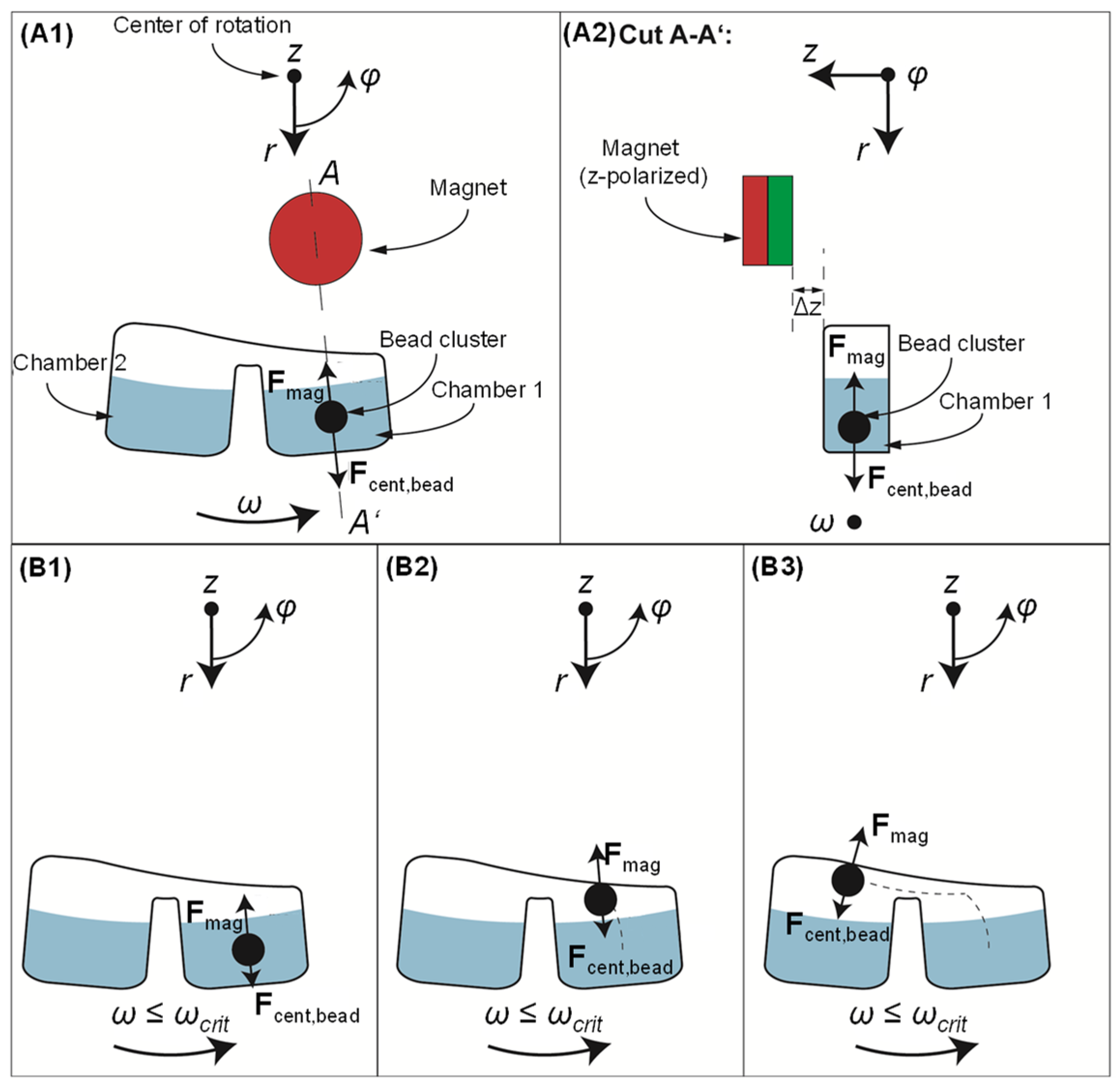
Abstract
1. Introduction
2. Magnetophoresis at Continuous Rotation
3. Materials and Methods
3.1. Permanent Magnet Setup
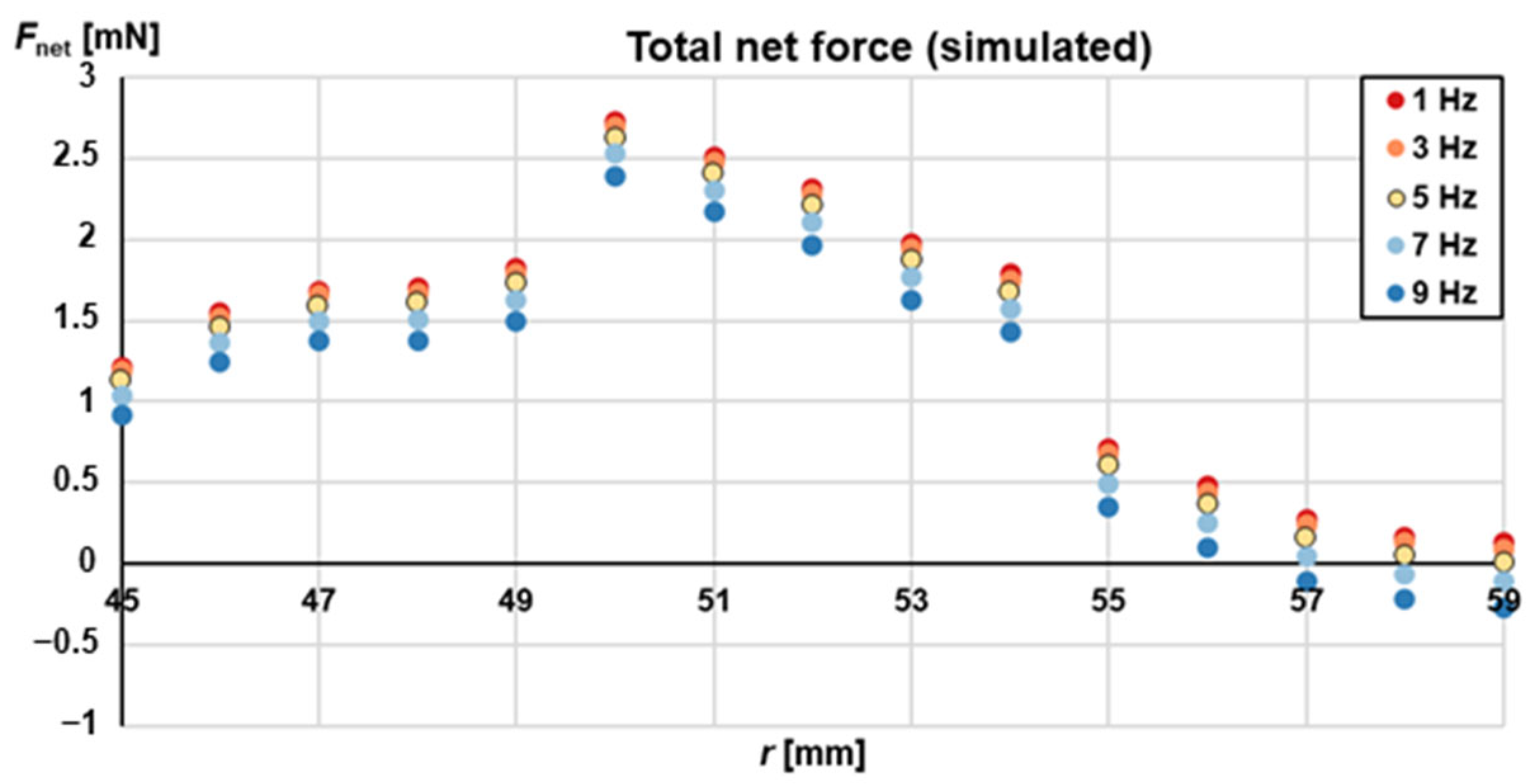
3.2. Simulation of the Magnetic Force
3.3. Measurement of Magnetic Flux Density
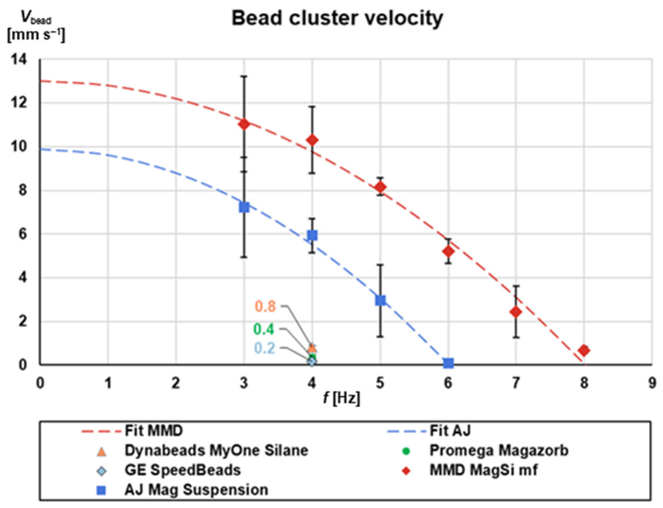
3.4. Measurement of Magnetic Bead Cluster Velocity
3.5. Manual Nucleic Acid Extraction
- Mixing of 150 μL lysis buffer and 200 μL sample;
- Incubation for 10 min at 350 rpm and 35 °C on a thermo mixer;
- Addition of 440 μL binding buffer and 20 μL magnetic beads;
- Collection of the beads for 3 min on the magnetic separator rack (‘MM12+12’, MagnaMedics Diagnostics BV—currently magtivio BV, Nuth, the Netherlands) in order to remove the supernatant;
- For the first washing step, addition of 200 μL washing buffer 1 into the tube;
- Incubation of the mixture for 2 min at 350 rpm and 35 °C on a thermo mixer;
- Separation of the beads for 3 min so that the supernatant could be pipetted out;
- For the second washing step: repetition of the same steps and volumes as washing step 1 was carried out (except that washing buffer 2 was used);
- For the elution step, addition of 180 μL elution buffer into the tube;
- Incubation of the mixture for 10 min at 350 rpm and 50 °C on a thermo mixer;
- Separation of the beads for 3 min on the magnetic separator rack;
- Pipetting out of the eluate and storage at −20 °C.
3.6. Manual Nucleic Acid Amplification on the Eluates
- Adjustment of the primer/probe concentrations at 100 nM RPS7_F, 200 nM RPS7_R and 250 nM RPS7_P;
- Mixing of the RPS7 primers with DNase/RNase-free water to a total volume of 9 μL;
- Addition of 1 μL eluate into this mixture, using a 1/16 fraction of a lyophilized amplification pellet (lyocake) per reaction (customized pellet including reverse transcriptase, Taq-Polymerase, Mg2+, nucleotides, buffer salts; GE Healthcare UK Limited, Chalfont St Giles, UK/Fast Track Diagnostics, Luxemburg);
- Realization of thermocycling under the following conditions: 5 min RT-step at 50 °C, 60 s initial denaturation at 95 °C, thermocycling 40 × (95 °C, 10 s and 60 °C, 60 s);
- Signal readout was done using the green channel;
- Data analysis was done with the Rotorgene Software (QIAGEN, Hilden, Germany), using the ‘dynamic tube’ and ‘slope correct’ filters. The first ten PCR cycles were not taken into account during baseline calculation. The threshold was manually set to 0.00686.
3.7. Spectrophotometric Analysis of the Eluates
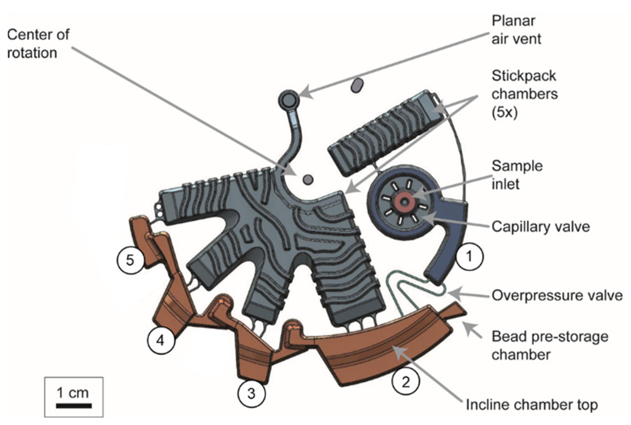
3.8. LabDisk Cartridge
4. Results and Discussion
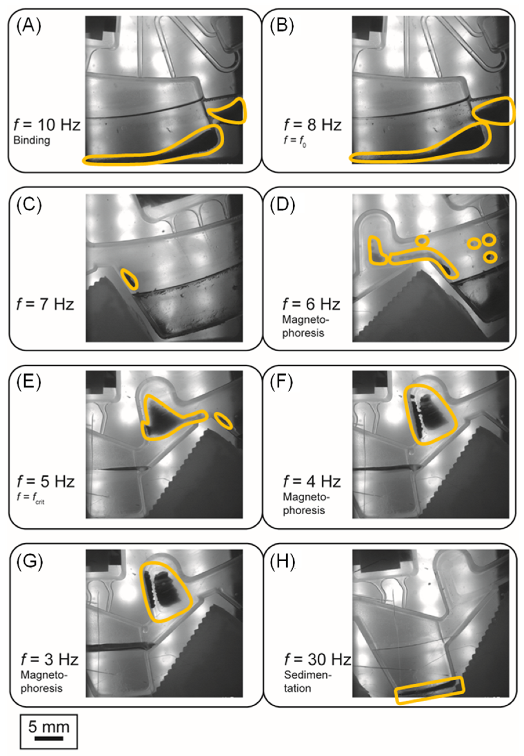
4.1. Definition of the Critical Frequency for Magnetophoresis under Rotation
4.2. Impact of Magnetic Bead Properties on Magnetophoresis under Rotation
4.3. Microfluidic Design and Protocol Supporting Magnetophoresis under Rotation
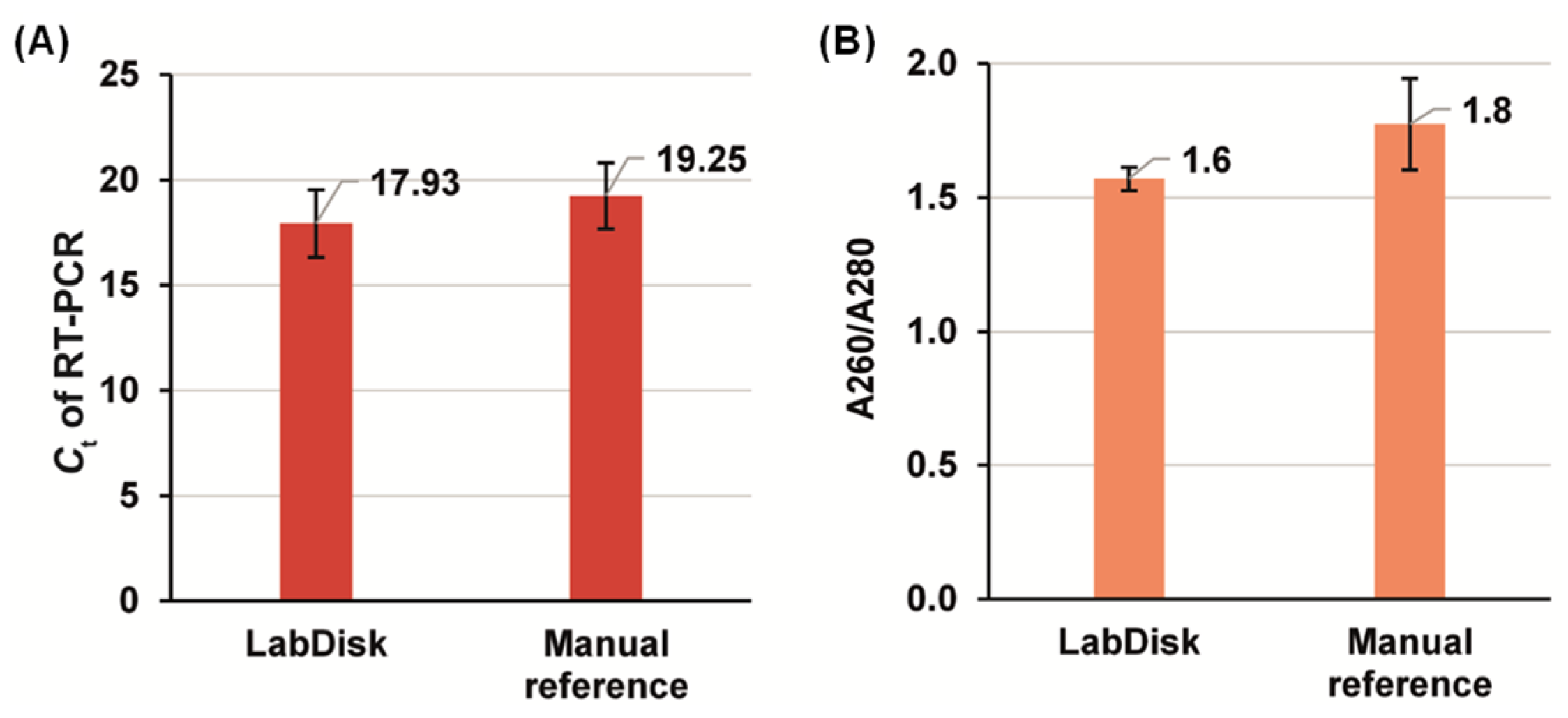
4.4. Nucleic Acid Extraction Using Magnetophoresis under Rotation
5. Conclusions
6. Patents
Supplementary Materials
Author Contributions
Funding
Data Availability Statement
Acknowledgments
Conflicts of Interest
References
- Stumpf, F.; Schwemmer, F.; Hutzenlaub, T.; Baumann, D.; Strohmeier, O.; Dingemanns, G.; Simons, G.; Sager, C.; Plobner, L.; von Stetten, F.; et al. LabDisk with complete reagent prestorage for sample-to-answer nucleic acid based detection of respiratory pathogens verified with influenza A H3N2 virus. Lab Chip 2016, 16, 199–207. [Google Scholar] [CrossRef] [PubMed]
- Hoehl, M.M.; Weißert, M.; Dannenberg, A.; Nesch, T.; Paust, N.; von Stetten, F.; Zengerle, R.; Slocum, A.H.; Steigert, J. Centrifugal LabTube platform for fully automated DNA purification and LAMP amplification based on an integrated, low-cost heating system. Biomed. Microdevices 2014, 16, 375–385. [Google Scholar] [CrossRef] [PubMed]
- Dignan, L.M.; Shane Woolf, M.; Tomley, C.J.; Nauman, A.Q.; Landers, J.P. Multiplexed Centrifugal Microfluidic System for Dynamic Solid-Phase Purification of Polynucleic Acids Direct from Buccal Swabs. Anal. Chem. 2021, 93, 7300–7309. [Google Scholar] [CrossRef] [PubMed]
- Rombach, M.; Hin, S.; Specht, M.; Johannsen, B.; Lüddecke, J.; Paust, N.; Zengerle, R.; Roux, L.; Sutcliffe, T.; Peham, J.R.; et al. RespiDisk: A point-of-care platform for fully automated detection of respiratory tract infection pathogens in clinical samples. Analyst 2020, 145, 7040–7047. [Google Scholar] [CrossRef]
- Baumgartner, D.; Johannsen, B.; Specht, M.; Lüddecke, J.; Rombach, M.; Hin, S.; Paust, N.; von Stetten, F.; Zengerle, R.; Herz, C.; et al. OralDisk: A Chair-Side Compatible Molecular Platform Using Whole Saliva for Monitoring Oral Health at the Dental Practice. Biosensors 2021, 11, 423. [Google Scholar] [CrossRef]
- Boom, R.; Sol, C.J.A.; Salimans, M.M.M.; Jansen, C.L.; Wertheim-Van Dillen, P.M.E.; van der Noordaa, J.P.M.E. Rapid and simple method for purification of nucleic acids. J. Clin. Microbiol. 1990, 28, 495–503. [Google Scholar] [CrossRef]
- Mitsakakis, K.; D’Acremont, V.; Hin, S.; von Stetten, F.; Zengerle, R. Diagnostic tools for tackling febrile illness and enhancing patient management. Microelectron. Eng. 2018, 201, 26–59. [Google Scholar] [CrossRef]
- Price, C.W.; Leslie, D.C.; Landers, J.P. Nucleic acid extraction techniques and application to the microchip. Lab Chip 2009, 9, 2484–2494. [Google Scholar] [CrossRef]
- Wen, J.; Legendre, L.A.; Bienvenue, J.M.; Landers, J.P. Purification of Nucleic Acids in Microfluidic Devices. Anal. Chem. 2008, 80, 6472–6479. [Google Scholar] [CrossRef]
- Yin, J.; Suo, Y.; Zou, Z.; Sun, J.; Zhang, S.; Wang, B.; Xu, Y.; Darland, D.; Zhao, J.X.; Mu, Y. Integrated microfluidic systems with sample preparation and nucleic acid amplification. Lab Chip 2019, 19, 2769–2785. [Google Scholar] [CrossRef]
- Cho, Y.-K.; Lee, J.-G.; Park, J.-M.; Lee, B.-S.; Lee, Y.; Ko, C. One-step pathogen specific DNA extraction from whole blood on a centrifugal microfluidic device. Lab Chip 2007, 7, 565–573. [Google Scholar] [CrossRef] [PubMed]
- Strohmeier, O.; Emperle, A.; Roth, G.; Mark, D.; Zengerle, R.; von Stetten, F. Centrifugal gas-phase transition magnetophoresis (GTM)—A generic method for automation of magnetic bead based assays on the centrifugal microfluidic platform and application to DNA purification. Lab Chip 2013, 13, 146–155. [Google Scholar] [CrossRef] [PubMed]
- Jackson, K.R.; Borba, J.C.; Meija, M.; Mills, D.L.; Haverstick, D.M.; Olson, K.E.; Aranda, R.; Garner, G.T.; Carrilho, E.; Landers, J.P. DNA purification using dynamic solid-phase extraction on a rotationally-driven polyethylene-terephthalate microdevice. Anal. Chim. Acta 2016, 937, 1–10. [Google Scholar] [CrossRef] [PubMed]
- McGaughey, K.D.; Yilmaz-Swenson, T.; Elsayed, N.M.; Cruz, D.A.; Rodriguez, R.R.; Kritzer, M.D.; Peterchev, A.V.; Gray, M.; Lewis, S.R.; Roach, J.; et al. Comparative evaluation of a new magnetic bead-based DNA extraction method from fecal samples for downstream next-generation 16S rRNA gene sequencing. PLoS ONE 2018, 13, e0202858. [Google Scholar] [CrossRef] [PubMed]
- Berensmeier, S. Magnetic particles for the separation and purification of nucleic acids. Appl. Microbiol. Biotechnol. 2006, 73, 495–504. [Google Scholar] [CrossRef]
- Hin, S.; Lopez-Jimena, B.; Bakheit, M.; Klein, V.; Stack, S.; Fall, C.; Sall, A.; Enan, K.; Mustafa, M.; Rusu, V.; et al. Fully automated point-of-care differential diagnosis of acute febrile illness. PLoS Neglect. Trop. Dis. 2021, 15, e0009177. [Google Scholar] [CrossRef] [PubMed]
- Mavridis, K.; Wipf, N.; Müller, P.; Traoré, M.M.; Muller, G.; Vontas, J. Detection and Monitoring of Insecticide Resistance Mutations in Anopheles gambiae: Individual vs. Pooled Specimens. Genes 2018, 9, 479. [Google Scholar] [CrossRef]
- Smerkova, K.; Rypar, T.; Adam, V.; Vaculovicova, M. Direct Magnetic Bead-Based Extraction of MicroRNA from Urine with Capillary Electrophoretic Analysis Using Fluorescence Detection and Universal Label. J. Biomed. Nanotechnol. 2020, 16, 76–84. [Google Scholar] [CrossRef]
- Balakrishnan, S.G.; Ahmad, M.R.; Koloor, S.S.R.; Petru, M. Separation of ctDNA by superparamagnetic bead particles in microfluidic platform for early cancer detection. J. Adv. Res. 2021, 33, 109–116. [Google Scholar] [CrossRef]
- Alnaimat, F.; Krishna, S.; Hilal-Alnaqbi, A.; Alazzam, A.; Dagher, S.; Mathew, B. 3D focusing of micro-scale entities in dielectrophoretic microdevice. Med. Devices Sens. 2019, 2, e10028. [Google Scholar] [CrossRef]
- Khashan, S.A.; Dagher, S.; Alazzam, A. Microfluidic multi-target sorting by magnetic repulsion. Microfluid. Nanofluid. 2018, 22, 64. [Google Scholar] [CrossRef]
- Kim, C.-J.; Park, J.; Sunkara, V.; Kim, T.-H.; Lee, Y.; Lee, K.; Kim, M.-H.; Cho, Y.-K. Fully automated, on-site isolation of cfDNA from whole blood for cancer therapy monitoring. Lab Chip 2018, 18, 1320–1329. [Google Scholar] [CrossRef] [PubMed]
- Brassard, D.; Geissler, M.; Descarreaux, M.; Tremblay, D.; Daoud, J.; Clime, L.; Mounier, M.; Charlebois, D.; Veres, T. Extraction of nucleic acids from blood: Unveiling the potential of active pneumatic pumping in centrifugal microfluidics for integration and automation of sample preparation processes. Lab Chip 2019, 19, 1941–1952. [Google Scholar] [CrossRef] [PubMed]
- World Health Organization. Vector-Borne Diseases Fact Sheet. Available online: https://www.who.int/news-room/fact-sheets/detail/vector-borne-diseases (accessed on 29 September 2022).
- Mitsakakis, K.; Hin, S.; Müller, P.; Wipf, N.; Thomsen, E.; Coleman, M.; Zengerle, R.; Vontas, J.; Mavridis, K. Converging Human and Malaria Vector Diagnostics with Data Management towards an Integrated Holistic One Health Approach. Int. J. Environ. Res. Public Health 2018, 15, 259. [Google Scholar] [CrossRef]
- Hemingway, J.; Field, L.; Vontas, J. An overview of insecticide resistance. Science 2002, 298, 96–97. [Google Scholar] [CrossRef]
- Ranson, H.; Lissenden, N. Insecticide resistance in African Anopheles Mosquitoes: A worsening situation that needs urgent action to maintain malaria control. Trends Parasitol. 2015, 32, 187–196. [Google Scholar] [CrossRef]
- Vontas, J.; Mitsakakis, K.; Zengerle, R.; Yewhalaw, D.; Sikaala, C.H.; Etang, J.; Fallani, M.; Carman, B.; Müller, P.; Chouaibou, M.; et al. Automated innovative diagnostic, data management and communication tool, for improving malaria vector control in endemic settings. Stud. Health Technol. Inform. 2016, 224, 54–60. [Google Scholar]
- Dusfour, I.; Vontas, J.; David, J.-P.; Weetman, D.; Fonseca, D.M.; Corbel, V.; Raghavendra, K.; Coulibaly, M.B.; Martins, A.J.; Kasai, S.; et al. Management of insecticide resistance in the major Aedes vectors of arboviruses: Advances and challenges. PLoS Neglect. Trop. Dis. 2019, 13, e0007615. [Google Scholar] [CrossRef]
- Schenck, J.F. The role of magnetic susceptibility in magnetic resonance imaging: MRI magnetic compatibility of the first and second kinds. Med. Phys. 1996, 23, 815–850. [Google Scholar] [CrossRef]
- Arrighini, G.P.; Maestro, M.; Moccia, R. Magnetic Properties of Polyatomic Molecules. I. Magnetic Susceptibility of H2O, NH3, CH4, H2O2. J. Chem. Phys. 1968, 49, 882–889. [Google Scholar] [CrossRef]
- Broersma, S. The Magnetic Susceptibility of Organic Compounds. J. Chem. Phys. 1949, 17, 873–882. [Google Scholar] [CrossRef]
- Gijs, M.A.M. Magnetic Bead Handling On-Chip: New Opportunities for Analytical Applications. Microfluid. Nanofluid. 2004, 1, 22–40. [Google Scholar] [CrossRef]
- Zborowski, M.; Sun, L.; Moore, L.R.; Stephen Williams, P.; Chalmers, J.J. Continuous cell separation using novel magnetic quadrupole flow sorter. J. Magn. Magn. Mater. 1999, 194, 224–230. [Google Scholar] [CrossRef]
- Shikida, M.; Takayanagi, K.; Honda, H.; Ito, H.; Sato, K. Development of an enzymatic reaction device using magnetic bead-cluster handling. J. Micromech. Microeng. 2006, 16, 1875–1883. [Google Scholar] [CrossRef]
- Munaz, A.; Shiddiky, M.J.A.; Nguyen, N.-T. Recent advances and current challenges in magnetophoresis based micro magnetofluidics. Biomicrofluidics 2018, 12, 31501. [Google Scholar] [CrossRef] [PubMed]
- Physical Magnet Data. Available online: https://www.supermagnete.de/eng/physical-magnet-data (accessed on 29 September 2022).
- Schindelin, J.; Arganda-Carreras, I.; Frise, E.; Kaynig, V.; Longair, M.; Pietzsch, T.; Preibisch, S.; Rueden, C.; Saalfeld, S.; Schmid, B.; et al. Fiji: An open-source platform for biological-image analysis. Nat. Methods 2012, 9, 676–682. [Google Scholar] [CrossRef]
- Magtivio, MagSi-DNA mf Beads Data Sheet. Available online: http://www.magtivio.com/wp-content/uploads/2019/05/PL0048-002_MagSi_DNA_mf_and_COOH.pdf (accessed on 29 September 2022).
- van Oordt, T.; Barb, Y.; Smetana, J.; Zengerle, R.; von Stetten, F. Miniature stick-packaging—An industrial technology for pre-storage and release of reagents in lab-on-a-chip systems. Lab Chip 2013, 13, 2888. [Google Scholar] [CrossRef]
- Foner, S. Versatile and Sensitive Vibrating-Sample Magnetometer. Rev. Sci. Instrum. 1959, 30, 548–557. [Google Scholar] [CrossRef]
- Lai, S.; Wang, S.; Luo, J.; Lee, L.J.; Yang, S.-T.; Madou, M.J. Design of a compact disk-like microfluidic platform for enzyme-linked immunosorbent assay. Anal. Chem. 2004, 76, 1832–1837. [Google Scholar] [CrossRef]
- Madou, M.J.; Lee, L.J.; Daunert, S.; Lai, S.; Shih, C.H. Design and Fabrication of CD-like Microfluidic Platforms for Diagnostics: Microfluidic Functions. Biomed. Microdevices 2001, 3, 245–254. [Google Scholar] [CrossRef]
- Schwemmer, F.; Blanchet, C.E.; Spilotros, A.; Kosse, D.; Zehnle, S.; Mertens, H.D.T.; Graewert, M.A.; Rössle, M.; Paust, N.; Svergun, D.I.; et al. LabDisk for SAXS: A centrifugal microfluidic sample preparation platform for small-angle X-ray scattering. Lab Chip 2016, 16, 1161–1170. [Google Scholar] [CrossRef] [PubMed]
- Grumann, M.; Geipel, A.; Riegger, L.; Zengerle, R.; Ducrée, J. Batch-mode mixing on centrifugal microfluidic platforms. Lab Chip 2005, 5, 560–565. [Google Scholar] [CrossRef] [PubMed]
- Berenguel-Alonso, M.; Granados, X.; Faraudo, J.; Alonso-Chamarro, J.; Puyol, M. Magnetic actuator for the control and mixing of magnetic bead-based reactions on-chip. Anal. Bioanal. Chem. 2014, 406, 6607–6616. [Google Scholar] [CrossRef]
- Donnelly, M.J.; Isaacs, A.T.; Weetman, D. Identification, validation, and application of molecular diagnostics for insecticide resistance in malaria vectors. Trends Parasitol. 2016, 32, 197–206. [Google Scholar] [CrossRef] [PubMed]
- Weetman, D.; Donnelly, M.J. Evolution of insecticide resistance diagnostics in malaria vectors. Trans. R. Soc. Trop. Med. Hyg. 2015, 109, 291–293. [Google Scholar] [CrossRef]
- Mavridis, K.; Wipf, N.; Medves, S.; Erquiaga, I.; Müller, P.; Vontas, J. Rapid multiplex gene expression assays for monitoring metabolic resistance in the major malaria vector Anopheles gambiae. Parasites Vectors 2019, 12, 9. [Google Scholar] [CrossRef]
- Müller, P.; Warr, E.; Stevenson, B.J.; Pignatelli, P.M.; Morgan, J.C.; Steven, A.; Yawson, A.E.; Mitchell, S.N.; Ranson, H.; Hemingway, J.; et al. Field-Caught Permethrin-Resistant Anopheles gambiae Overexpress CYP6P3, a P450 That Metabolises Pyrethroids. PLoS Genet. 2008, 4, e1000286. [Google Scholar] [CrossRef]
- Stevenson, B.J.; Bibby, J.; Pignatelli, P.; Muangnoicharoen, S.; O’Neill, P.M.; Lian, L.-Y.; Müller, P.; Nikou, D.; Steven, A.; Hemingway, J.; et al. Cytochrome P450 6M2 from the malaria vector Anopheles gambiae metabolizes pyrethroids: Sequential metabolism of deltamethrin revealed. Insect Biochem. Mol. Biol. 2011, 41, 492–502. [Google Scholar] [CrossRef]
- Eppendorf User Guide. Available online: https://www.eppendorf.com/product-media/doc/de/59828/Eppendorf_Detection_Application-Note_279_BioPhotometer-D30_Detection-contamination-DNA-protein-samples-photometric-measurements.pdf (accessed on 29 September 2022).
- Focke, M.; Kosse, D.; Al-Bamerni, D.; Lutz, S.; Müller, C.; Reinecke, H.; Zengerle, R.; von Stetten, F. Microthermoforming of microfluidic substrates by soft lithography (μTSL): Optimization using design of experiments. J. Micromech. Microeng. 2011, 21, 115002. [Google Scholar]
- Rombach, M.; Kosse, D.; Faltin, B.; Wadle, S.; Roth, G.; Zengerle, R.; von Stetten, F. Real-time stability testing of air-dried primers and fluorogenic hydrolysis probes stabilized by trehalose and xanthan. BioTechniques 2014, 57, 151–155. [Google Scholar] [CrossRef]


Publisher’s Note: MDPI stays neutral with regard to jurisdictional claims in published maps and institutional affiliations. |
© 2022 by the authors. Licensee MDPI, Basel, Switzerland. This article is an open access article distributed under the terms and conditions of the Creative Commons Attribution (CC BY) license (https://creativecommons.org/licenses/by/4.0/).
Share and Cite
Hin, S.; Paust, N.; Rombach, M.; Lüddecke, J.; Specht, M.; Zengerle, R.; Mitsakakis, K. Magnetophoresis in Centrifugal Microfluidics at Continuous Rotation for Nucleic Acid Extraction. Micromachines 2022, 13, 2112. https://doi.org/10.3390/mi13122112
Hin S, Paust N, Rombach M, Lüddecke J, Specht M, Zengerle R, Mitsakakis K. Magnetophoresis in Centrifugal Microfluidics at Continuous Rotation for Nucleic Acid Extraction. Micromachines. 2022; 13(12):2112. https://doi.org/10.3390/mi13122112
Chicago/Turabian StyleHin, Sebastian, Nils Paust, Markus Rombach, Jan Lüddecke, Mara Specht, Roland Zengerle, and Konstantinos Mitsakakis. 2022. "Magnetophoresis in Centrifugal Microfluidics at Continuous Rotation for Nucleic Acid Extraction" Micromachines 13, no. 12: 2112. https://doi.org/10.3390/mi13122112
APA StyleHin, S., Paust, N., Rombach, M., Lüddecke, J., Specht, M., Zengerle, R., & Mitsakakis, K. (2022). Magnetophoresis in Centrifugal Microfluidics at Continuous Rotation for Nucleic Acid Extraction. Micromachines, 13(12), 2112. https://doi.org/10.3390/mi13122112