

Investigations on Stub-Based UWB-MIMO Antennas to Enhance Isolation Using Characteristic Mode Analysis


 ,
,  , ,
, ,
Abstract
1. Introduction
Novelty and Contributions
- The proposed compact 2 × 2 and 4 × 4 UWB-MIMO antennas achieved −25 dB isolation among elements using Characteristic Mode Analysis (CMA).
- The designed antennas not only cover UWB but also cover the X and ITU bands.
- The decoupling I-shaped stub is placed at ground level to enhance the isolation and overall performance of the MIMO antennas.
- A step-by-step systematic designing approach using CMA methodology is used to achieve good diversity characteristics in operating frequency range.
- Both 2 × 2 and 4 × 4 antennas achieve good gain and radiation efficiencies.
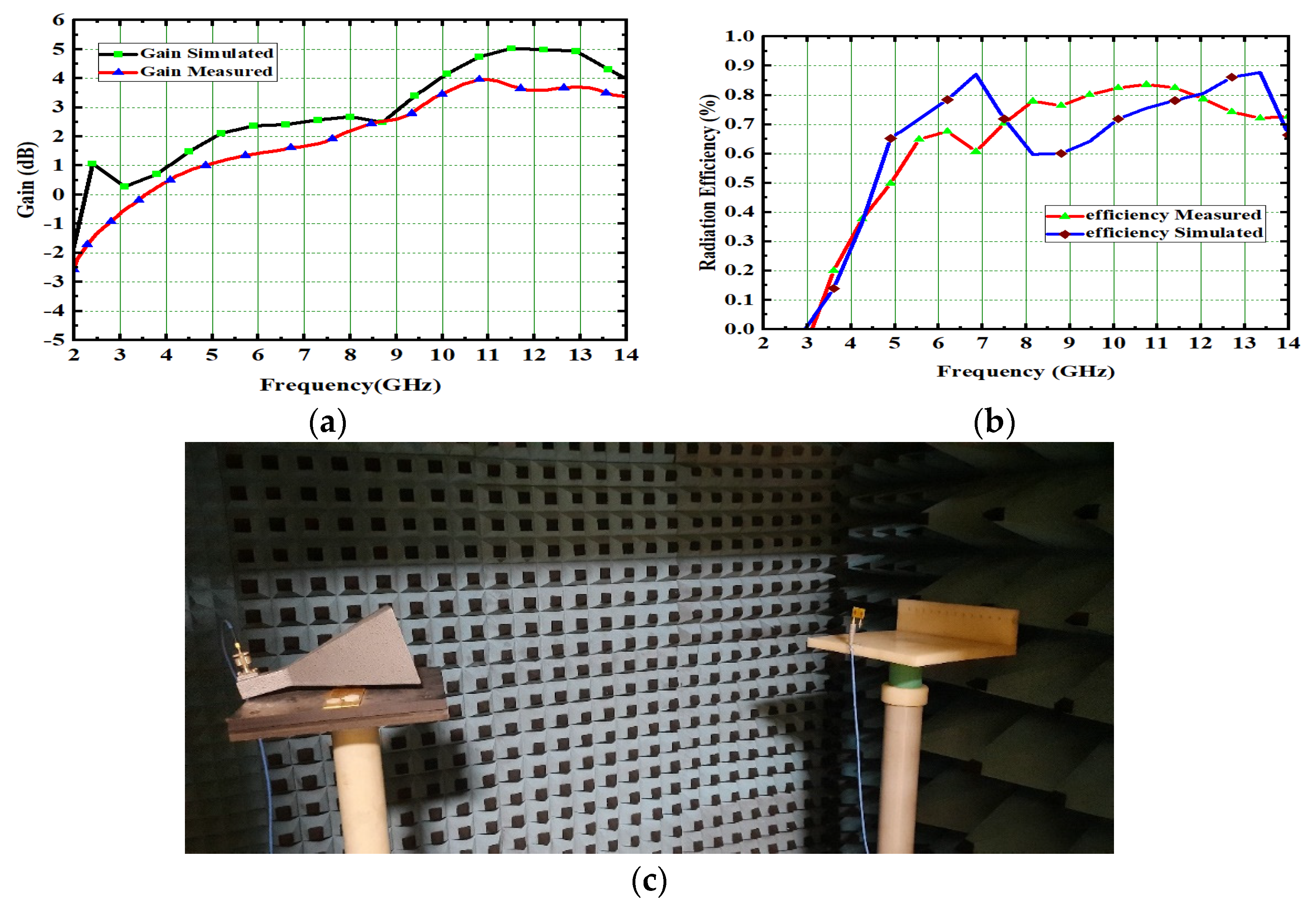
- The designed 2 × 2 UWB-MIMO achieved a peak gain and radiation efficiency of 4.2 dB and 82.5%, respectively. Therefore, there is a scope to enhance the above said parameters by changing the 2 × 2 configuration into a 4 × 4 MIMO arrangement.
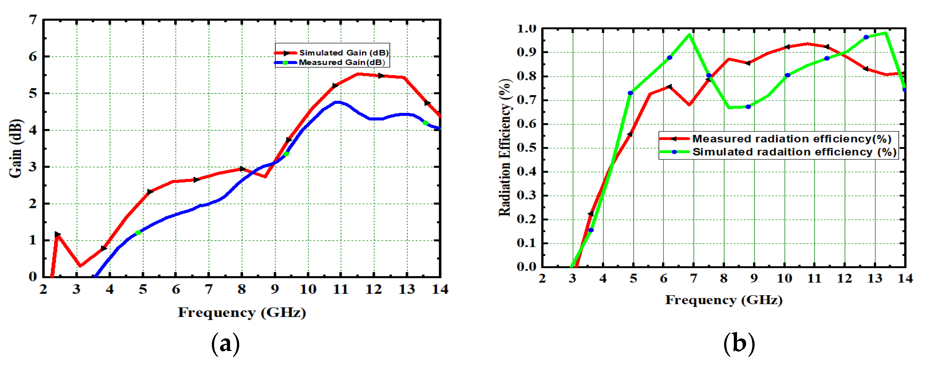
- The proposed 4 × 4 UWB-MIMO with CMA achieved gain and radiation efficiency up to 4.8 dB and 92.2%, respectively. The ECC of 2 × 2 is also reduced from 0.005 to 0.0045 by designing 4 × 4 MIMO antenna.
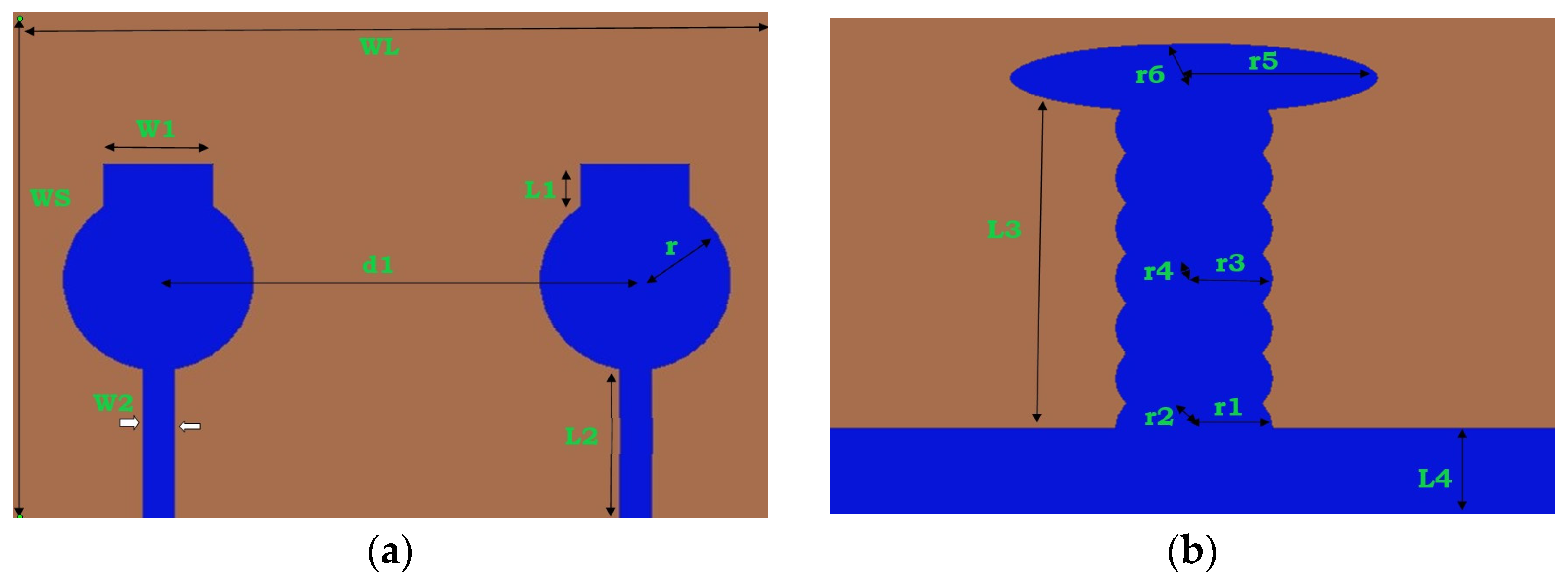
2. Antenna Design
2.1. UWB-MIMO Using CMA
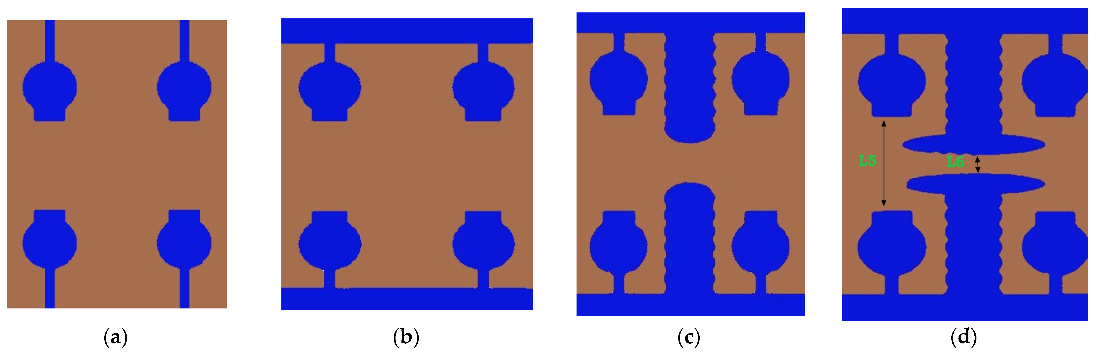
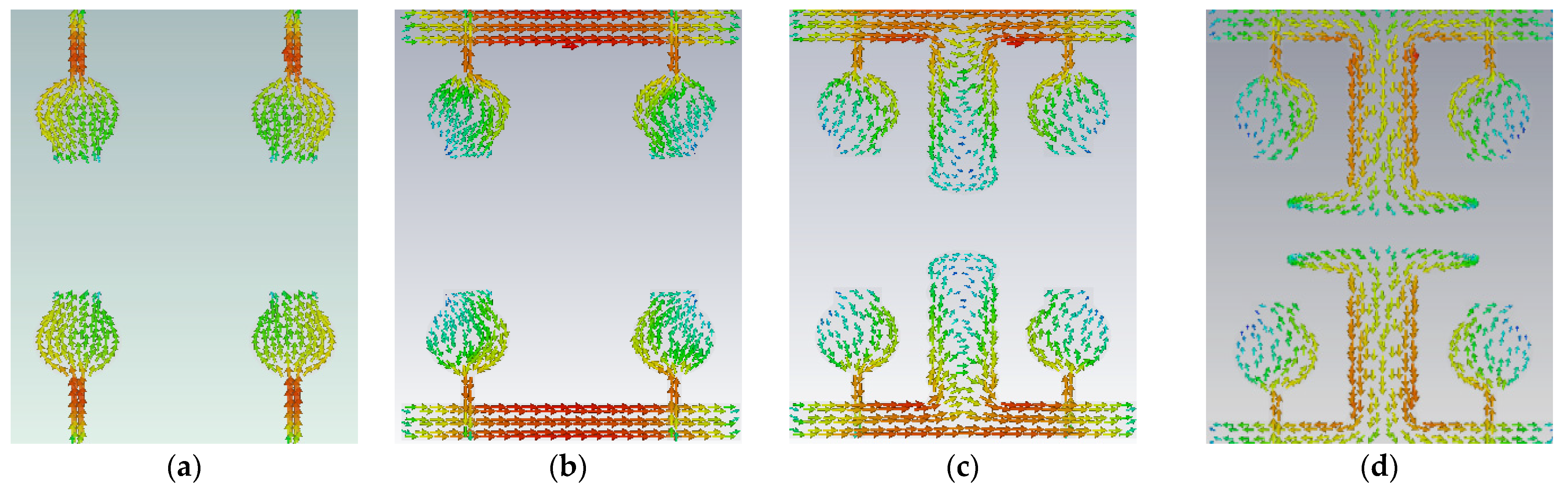
2.2. Effect of Decoupling Stub
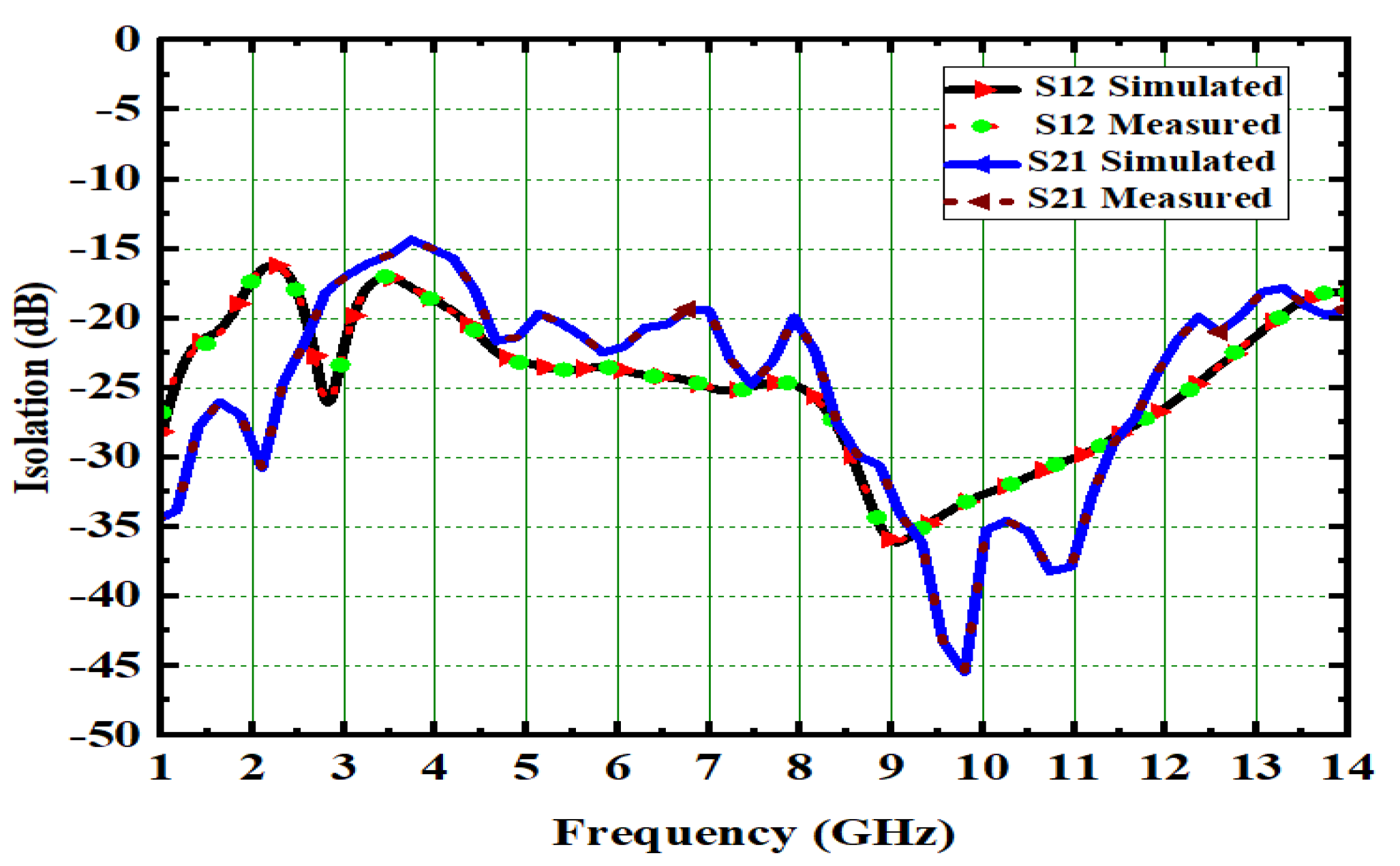
3. Results of High-Compact 2 × 2 UWB-MIMO Antenna
4. 4 × 4. UWB-MIMO Antenna Design
5. Results of High-Compact 4 × 4 UWB-MIMO Antenna
5.1. 4 × 4 MIMO Gain and Radiation Efficiency
5.2. Diversity Parameters
5.2.1. ECC and DG
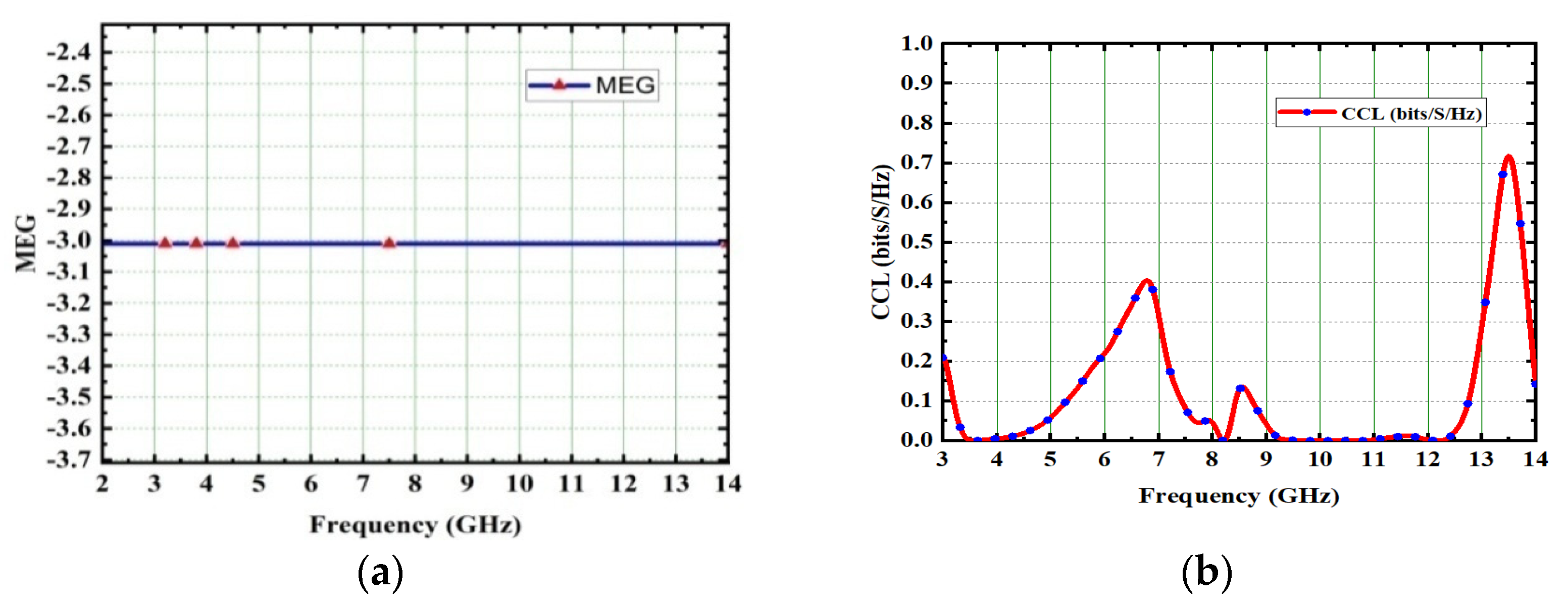
5.2.2. MEG
5.2.3. The Channel Capacity Loss
6. Comparisons of Proposed Work with other Models
7. Conclusions
Author Contributions
Funding
Data Availability Statement
Acknowledgments
Conflicts of Interest
References
- Awan, W.A.; Zaidi, A.; Hussain, M.; Hussain, N.; Syed, I. The design of a wideband antenna with notchingcharacteristics for small devices using a genetic algorithm. Mathematics 2021, 9, 2113. [Google Scholar] [CrossRef]
- Jayanthi, K.; Kalpana, A.M. Mutual coupling reduction techniques between MIMO antennas for UWB. Int. J. Recent Innov. Trends Comput. Commun. 2017, 5, 18–22. [Google Scholar] [CrossRef]
- Nadeem, I.; Choi, D.Y. Study on Mutual Coupling Reduction Technique for MIMO Antennas. IEEE Access 2018, 7, 563–586. [Google Scholar] [CrossRef]
- Liu, F.; Guo, J.; Zhao, L.; Huang, G.L.; Li, Y.; Yin, Y. Dual-band meta surface-based decoupling method for two closely packed dual-band antennas. IEEE Trans. Antennas Propag. 2019, 68, 552–557. [Google Scholar] [CrossRef]
- Radhi, A.H.; Nilavalan, R.; Wang, Y.; Al-Raweshidy, H.S.; Eltokhy, A.A.; Ab Aziz, N. Mutual coupling reduction with a wideband planar decoupling structure for UWB–MIMO antennas. Int. J. Microw. Wirel. Technol. 2018, 10, 1143–1154. [Google Scholar] [CrossRef]
- Mohanty, A.; Sahu, S. High isolation two-port compact MIMO fractal antenna with Wi-Max and X-band suppression characteristics. Int. J. RF Microw. Comput.-Aided Eng. 2019, 30, e22021. [Google Scholar] [CrossRef]
- Mathur, R.; Dwari, S. A compact UWB-MIMO with dual grounded CRR for isolation improvement. Int. J. RF Microw. Comput.-Aided Eng. 2018, 29, e21500. [Google Scholar] [CrossRef]
- Prabhu, T.; Pandian, S.C. Design and Implementation of T-Shaped Planar Antenna for MIMO Applications. Comput. Mater. Contin. 2021, 69, 2549–2562. [Google Scholar] [CrossRef]
- Bukkawar, S.; Ahmed, V. Compact slot-loaded ultra-wideband multiple-input multiple-output antenna with fractal-inspired isolator. Int. J. RF Microw. Comput.-Aided Eng. 2019, 30, e22036. [Google Scholar] [CrossRef]
- Raheja, D.K.; Kanaujia, B.K.; Kumar, S. Compact four-port MIMO antenna on slottededge substrate with dual-band rejection characteristics. Int. J. RF Microw. Comput.-Aided Eng. 2019, 29, e21756. [Google Scholar] [CrossRef]
- Biswal, S.P.; Das, S. A compact printed ultra-wideband multiple-input multiple-output prototype with band-notch ability for WiMAX, LTEband43, and WLAN system. Int. J. RF Microw. Comput.-Aided Eng. 2019, 10, e21673. [Google Scholar] [CrossRef]
- Gomez-Villanueva, R.; Jardon-Aguilar, H. Compact UWB uniplanar four-port MIMO antenna array with rejecting band. IEEE Antennas Wirel. Propag. Lett. 2019, 18, 2543–2547. [Google Scholar] [CrossRef]
- Premalatha, J.; Sheela, D. Compact four-port vertically polarized UWB monopole antenna for MIMO Communications. Circuit World 2021, 47, 129–137. [Google Scholar] [CrossRef]
- Tiwari, R.N.; Singh, P.; Kanaujia, B.K.; Srivastava, K. Neutralization technique based two and four port high isolation MIMO antennas for UWB communication. AEU-Int. J. Electron. Commun. 2019, 110, 152828. [Google Scholar] [CrossRef]
- Nikam, B.V.; Jadhav, M.R. A Compact Quad Port Band-Notched MIMO Antenna for Wi-Max Applications with Low Mutual Coupling. Prog. Electromagn. Res. C 2020, 104, 53–67. [Google Scholar] [CrossRef]
- Khan, A.A.; Naqvi, S.A.; Khan, M.S.; Ijaz, B. Quad port miniaturized MIMO antenna for UWB 11 GHz and 13 GHz frequency bands. AEU-Int. J. Electron. Commun. 2021, 131, 153618. [Google Scholar] [CrossRef]
- Yang, R.; Xi, S.; Cai, Q.; Chen, Z.; Wang, X.; Liu, G. A Compact Planar Dual-Band Multiple-Input and Multiple-Output Antenna with High Isolation for 5G and 4G Applications. Micromachines 2021, 12, 544. [Google Scholar] [CrossRef] [PubMed]
- Garbacz, R.J. Modal expansions for resonance scattering phenomena. Proc. IEEE 1965, 53, 856–864. [Google Scholar] [CrossRef]
- Barzegari, S.; Forooraghi, K.; Abbasi Arand, B. Design of circularly polarized planar leaky-wave antenna using characteristic mode analysis. IET Microw. Antennas Propag. 2021, 15, 1086–1099. [Google Scholar] [CrossRef]
- Harrington, R.; Mautz, J. Computation of characteristic modes for conducting bodies. IEEE Trans. Antennas Propag. 1971, 9, 629–639. [Google Scholar] [CrossRef]
- Kumar, P.; Ali, T.; MM, M.P. Characteristic Mode Analysis-Based Compact Dual Band-Notched UWB MIMO Antenna Loaded with Neutralization Line. Micromachines 2022, 13, 1599. [Google Scholar] [CrossRef] [PubMed]
- Cabedo-Fabres, M.; Antonino-Daviu, E.; Valero-Nogueira, A.; Bataller, M.F. The theory of characteristic modes revisited. A contribution to the design of antennas for modern applications. IEEE Antennas Propag. Mag. 2020, 5, 52–68. [Google Scholar] [CrossRef]
- Li, K.; Shi, Y. Wideband MIMO handset antenna design based on theory of characteristic modes. Int. J. RF Microw. Comput.-Aided Eng. 2018, 28, e21217. [Google Scholar] [CrossRef]
- Kumar, N.; Khanna, R. A compact multi-band multi-input multi-output antenna for 4G/5G and IoT devices using theory of characteristic modes. Int. J. RF Microw. Comput.-Aided Eng. 2020, 30, e22012. [Google Scholar] [CrossRef]
- Zhao, X.; Yeo, S.P.; Ong, L.C. Planar UWB MIMO antenna with pattern diversity and isolation improvement for mobile platform based on the theory of characteristic modes. IEEE Trans. Antennas Propag. 2018, 66, 420–425. [Google Scholar] [CrossRef]
- Nie, L.Y.; Lin, X.Q.; Yang, Z.Q.; Zhang, J.; Wang, B. Structure-shared planar UWB MIMO antenna with high isolation for mobile platform. IEEE Trans. Antennas Propag. 2019, 67, 2735–2738. [Google Scholar] [CrossRef]
- Medkour, H.; Lakrit, S.; Das, S.; Madhav, B.T.P.; VasuBabu, K. A Compact Printed UWB MIMO Antenna with Electronically Reconfigurable WLAN Band-Notched Characteristics. J. Circuits Syst. Comput. 2021, 31, 2250045. [Google Scholar] [CrossRef]
- Addepalli, T.; Anitha, V.R. A very compact and closely spaced circular shaped UWB MIMO antenna with improved isolation. AEU-Int. J. Electron. Commun. 2020, 114, 153016. [Google Scholar] [CrossRef]
- Alharbi, A.G.; Rafique, U.; Ullah, S.; Khan, S.; Abbas, S.M.; Ali, E.M.; Alibakhshikenari MDalarsson, M. Novel MIMO Antenna System for Ultra-Wideband Applications. Appl. Sci. 2022, 12, 3684. [Google Scholar] [CrossRef]
- Zaidi, A.; Awan, W.A.; Ghaffar, A.; Alzaidi, M.S.; Alsharef, M.; Elkamchouchi, D.H.; Ghoneim, S.S.; Alharbi, T.E. A Low Profile Ultra-Wideband Antenna with Reconfigurable Notch Band Characteristics for Smart Electronic Systems. Micromachines 2022, 13, 1803. [Google Scholar] [CrossRef]
- Awan, W.A.; Hussain, N.; Ghaffar, A.; Zaidi, A.; Naqvi, S.I.; Li, X.J. Compact Flexible Frequency Reconfigurable Antenna for Heterogeneous Applications. In Proceedings of the 2020 9th Asia-Pacific Conference on Antennas and Propagation (APCAP), Xiamen, China, 4–7 August 2020; pp. 1–2. [Google Scholar] [CrossRef]
- Khan, M.K.; Khan, M.I.; Ahmad, I.; Saleem, M. Design of a Printed Monopole Antenna with Ridged Ground for Ultra Wide Band Applications. In Proceedings of the 2016 Progress in Electromagnetics Research (PIERS), Shanghai, China, 8–11 August 2016; pp. 4394–4396. [Google Scholar] [CrossRef]
- Rahman, S.U.; Cao, Q.; Ullah, H.; Khalil, H. Compact design of trapezoid shape monopole antenna for SWB application. Microw. Opt. Technol. Lett. 2019, 61, 1931–1937. [Google Scholar] [CrossRef]
- Khan, M.S.; Iftikhar, A.; Shubair, R.M.; Capobianco, A.D.; Braaten, B.D.; Anagnostou, D.E. A four element, planar, compact UWB MIMO antenna with WLAN band rejection capabilities. Microw. Opt. Technol. Lett. 2020, 62, 3124–3131. [Google Scholar] [CrossRef]
- Singh, H.V.; Tripathi, S. Compact UWB MIMO antenna with Fork-shaped stub with vias based coupling current steering (VBCCS) to enhance isolation using CMA. AEU-Int. J. Electron. Commun. 2021, 129, 153550. [Google Scholar] [CrossRef]
- Suresh, A.C.; Reddy, T.S. High Isolation With Fork-Shaped Stub In Compact UWB-MIMO Antenna Using CMA. In Proceedings of the 2021 International Conference on Recent Trends on Electronics, Information, Communication & Technology (RTEICT), Bengaluru, India, 27–28 August 2021; pp. 505–511. [Google Scholar] [CrossRef]
- Sultan, K.S.; Abdullah, H.H. Planar UWB MIMO-diversity antenna with dual notch characteristics. Prog. Electromagn. Res. C 2019, 93, 119–129. [Google Scholar] [CrossRef]
- Abdulkawi, W.M.; Malik, W.A.; Rehman, S.U.; Aziz, A.; Sheta, A.F.A.; Alkanhal, M.A. Design of a Compact Dual-Band MIMO Antenna System with High-Diversity Gain Performance in Both Frequency Bands. Micromachines 2021, 12, 383. [Google Scholar] [CrossRef]
- Abbas, A.; Hussain, N.; Sufian, A.; Jung, J.; Park, S.M.; Kim, N. Isolation and Gain Improvement of a Rectangular Notch UWB-MIMO Antenna. Sensors 2022, 22, 1460. [Google Scholar] [CrossRef]


| L1 | L2 | L3 | d1 | W1 | W2 |
|---|---|---|---|---|---|
| 2 | 7 | 12.5 | 17.5 | 4 | 1.2 |
| L4 | r1 | r2 | r3 | r4 | r5 |
| 3.4 | 3 | 2 | 3 | 2 | 7 |
| r6 | Ws | WL | Wh | hp | L5 |
| 1.735 | 20 | 20 & 40 | 1.4 | 0.035 | 8 |
| L6 | r | ||||
| 8 | 3.6 |
| Ref. | Design Methodology | Dimensions (mm2) | Isolation (dB) | ECC | CCL (b/s/Hz) |
|---|---|---|---|---|---|
| [2] | Inverted L-shaped strip | 60 × 30 | 34 | 0.002 | 0.5 |
| [3] | Decoupling stubs in hexagonal shape | 34 × 20 | 20 | 0.2 | --- |
| [4] | I-shaped decoupling stub | 25 × 25 | 17 | 0.01 | --- |
| [6] | Fractal slot and flipped in horizontal | 53 × 35 | 19 | 0.007 | --- |
| [7] | cut in substrate and placed orthogonal | 58 × 28 | 20 | 0.008 | --- |
| [8] | U-Shaped with T-shaped decoupling stub | 30 × 45 | 29.5 | 0.00185 | --- |
| [19] | Pattern diversity with CMT | 85 × 50 | 20 | 0.03 | --- |
| [23] | CSRR and decoupling stub inverted L-shape | 23 × 29 | 15 | 0.15 | --- |
| [30] | T-shaped Stub | 18 × 36 × 18.5 | 20 | 0.02 | --- |
| [32] | Space diversity | 60 × 60 | 16 | 0.005 | --- |
| [35] | Characteristic Mode Analysis (CMA) with vias and fork-shaped stubs | 20 × 28 | 23 | 0.005 | --- |
| Prop (2) | CMA with T-shaped decoupling Stub | 28 × 20 × 1.6 | 23 | 0.005 | 0.029 |
| [5] | Placement in orthogonal form | 38 × 38 | 20 | 0.01 | 0.4 |
| [9] | Polarized diversity with defected ground system | 38.3 × 38.3 | 17 | 0.02 | --- |
| [10] | Fractal slot and flipped in horizontal | 40 × 40 | 12 | 0.07 | 0.4 |
| [32] | Space diversity and pattern diversity | 90 × 60 | 20 | 0.005 | --- |
| [35] | Characteristic Mode Analysis (CM) with vias and Fork-shaped stubs | 40 × 28 | 17 | 0.01 | --- |
| [39] | Parasitic decoupler | 60 × 60 × 1.52 | 21 | 0.001 | -- |
| Prop (44) | CMA with T-shaped decoupling Stub | 28 × 40 × 1.6 | 25 | 0.0045 | 0.39 |
Publisher’s Note: MDPI stays neutral with regard to jurisdictional claims in published maps and institutional affiliations. |
© 2022 by the authors. Licensee MDPI, Basel, Switzerland. This article is an open access article distributed under the terms and conditions of the Creative Commons Attribution (CC BY) license (https://creativecommons.org/licenses/by/4.0/).
Share and Cite
Suresh, A.C.; Reddy, T.S.; Madhav, B.T.P.; Das, S.; Lavadiya, S.; Algarni, A.D.; El-Shafai, W. Investigations on Stub-Based UWB-MIMO Antennas to Enhance Isolation Using Characteristic Mode Analysis. Micromachines 2022, 13, 2088. https://doi.org/10.3390/mi13122088
Suresh AC, Reddy TS, Madhav BTP, Das S, Lavadiya S, Algarni AD, El-Shafai W. Investigations on Stub-Based UWB-MIMO Antennas to Enhance Isolation Using Characteristic Mode Analysis. Micromachines. 2022; 13(12):2088. https://doi.org/10.3390/mi13122088
Chicago/Turabian StyleSuresh, Ankireddy Chandra, Thatiparthi Sreenivasulu Reddy, Boddapati Taraka Phani Madhav, Sudipta Das, Sunil Lavadiya, Abeer D. Algarni, and Walid El-Shafai. 2022. "Investigations on Stub-Based UWB-MIMO Antennas to Enhance Isolation Using Characteristic Mode Analysis" Micromachines 13, no. 12: 2088. https://doi.org/10.3390/mi13122088
APA StyleSuresh, A. C., Reddy, T. S., Madhav, B. T. P., Das, S., Lavadiya, S., Algarni, A. D., & El-Shafai, W. (2022). Investigations on Stub-Based UWB-MIMO Antennas to Enhance Isolation Using Characteristic Mode Analysis. Micromachines, 13(12), 2088. https://doi.org/10.3390/mi13122088