Abstract
A dual-band, dual-polarized filtering antenna with a cross-shaped dielectric strip resonator is proposed. The dual-band filtering radiation function is achieved by utilizing the odd and even modes of the stub loaded microstrip resonator to excite the TMδ1 and TMδ3 mode in each polarization direction of the cross-shaped dielectric strip resonator. The cross-shaped dielectric strip resonator is synthesized by the E-field distributions and the magnitude comparison along different polarization directions, which can ensure the isolation between two polarizations. Compared with dual-band filtering dielectric antennas, the proposed antenna has the characteristic of dual-polarized radiation, as well as a low profile. A prototype is fabricated and measured, which operates at 3.5 GHz and 4.9 GHz with the fractional bandwidths (FBW) of 5.40% and 2.03%, respectively, and the gains of these two bands are 6.4 dBi and 6.2 dBi, respectively. The two radiation nulls are located at 4.4 GHz and 5.1 GHz. Furthermore, the measured isolation between the two ports in the frequency band can achieve 16 dB.
1. Introduction
With the advances in wireless communication technology, antennas are widely used as a radio frequency front end for transmitting and receiving signals. Among them, the filtering dielectric antenna [1,2,3,4,5,6] has attracted much attention because it has both the advantages of filtering antenna that reduce the filter requirements in the system and effectively reduces the mutual coupling between two antennas working in adjacent frequency bands. It also has the advantages of dielectric antenna with low loss, high efficiency, and high design freedom. The dual-band antenna [7,8] and dual-polarized antenna [9,10,11] reduce the size of the system, reduce the cost, and improve the communication efficiency from the aspects of frequency band number and polarization number, respectively. Therefore, it is valuable to design a dual-band, dual-polarized filtering dielectric antenna.
In accordance with research, the majority of the existing dual-band, dual-polarized filtering antennas are ground on metal radiators [12,13,14,15,16,17,18,19]. In [12], an upper-band filtering cross dipole is embedded into a lower-band filtering magnetoelectric dipole for realizing the dual-band, dual-polarized filtering operation. In [13], through open-circuit, stepped-impedance resonators added microstrip line to feed four slots etched patch, a ±45° polarized dual-band filtering patch antenna is realized. In [14], with the introduction of a vertical corner pin inside the cavity, TE210 mode and TE120 mode radiation frequencies can be controlled to realize dual-band operation. In [15], by combining a cross slot pair, four shorting pins, and four parasitic strips, a band-notched property between two operation bands is obtained. In [16], by using the C-shaped and L-shaped filtering structure to feed lower-band and upper-band dipoles, a dual-band filtering response with dual-polarized radiation is achieved. In [17], by employing a dual-mode, stub-loaded resonator to feed the X-band and C-band patches, the dual-band filtering radiation function and dual-polarized radiation are realized at the same time. In [18], the dual-band, dual-polarized filtering characteristics are performed by placing four upper-band patch antennas on the lower-band slot antenna and using microstrip lines in the radiating slots to couple to the open-ended stubs on the feeder. In [19], dual-band, dual-polarized characteristics are achieved by using two fully-shielded, quarter-mode substrate-integrated waveguide cavities to excite the upper-band and lower-band patches.
The dual-band filtering dielectric antenna reported is only single-polarized [20,21,22,23]. In [20], the dielectric resonator and the slot lines contribute to two radiation frequency bands, and the open stubs of the feedline and the coupled slot lines accomplish three radiation nulls. In [21], the dual-mode dielectric radiator uses the quadruple-mode, stub-loaded loop resonator to feed, and realizes the dual-band filtering characteristics. In [22], the dual-mode dielectric resonator uses a microstrip line feed to realize the dual-band filtering design with higher frequency selectivity. In [23], the dual-band characteristic is achieved by even-mode coupling between three dielectric strip resonators. The odd-mode coupling between the dielectric strip resonators produces two radiation nulls. The above-mentioned dual-band, single-polarized filtering dielectric antennas have directional radiation, and in addition, some omnidirectional radiation dual-band, single-polarized filtering dielectric antennas are reported [24,25,26]. As a conclusion, to our knowledge, no dual-band, dual-polarized filtering dielectric antennas have been reported yet.
In this paper, a dual-band, dual-polarized filtering dielectric antenna utilized by the cross-shaped dielectric strip resonator is proposed for the first time. The TMδ1 and TMδ3 modes of each polarization direction for the cross-shaped dielectric strip resonator are excited through the odd and even modes of the stub-loaded microstrip resonator, thereby realizing the dual-band filtering operation. The electric field distribution of the TMδ1 mode (TMδ3 mode) is concentrated in one polarization direction of the cross-shaped dielectric strip resonator, while that of the other polarization direction is weak, thus ensuring the isolation of the two polarizations. The dielectric resonator and the microstrip resonator are analyzed and a prototype is designed and compared with the existing works.
2. Proposed Dual-Band, Dual-Polarized Filtering Antenna Based on Cross-Shaped Dielectric Strip Resonator
As shown in Figure 1, the proposed dual-band, dual-polarized filtering dielectric antenna consists of a cross-shaped dielectric strip resonator at the top layer of substrate 1, a horizontal slotted and vertical slotted ground are located in the middle of substrate 1 and substrate 2, and two middle-loaded, open-circuit stub dual-mode microstrip resonators are located on the bottom layer. The cross-shaped dielectric strip resonator is on ceramic sheets (εr1 = 89.5 and tan δ1 = 0.0006), while two substrates are RO4003C substrates (εr2 = 3.38 and tan δ2 = 0.0027). The full-wave simulation is undertaken using computer simulation technology.
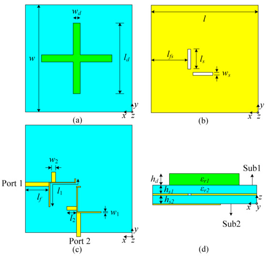
Figure 1.
Configuration of the proposed antenna: (a) top layer; (b) middle layer; (c) bottom layer; (d) side view.
2.1. Cross-Shaped Dielectric Strip Resonator
Figure 2a shows the structure of the cross-shaped dielectric strip resonator, which is mainly composed of a cross-shaped dielectric strip with a high relative permittivity (εr1) of 89.5 on the top layer. Located in the middle layer is a substrate with low relative permittivity (εr2) of 3.38, and the bottom layer is a metal ground. Figure 2b,c shows the electric field distribution of the TMδ1 and TMδ3 modes of the cross-shaped dielectric strip resonator, respectively. As shown from Figure 2b, the resonant mode is mainly the TMδ1 mode on the dielectric strip resonators in horizontal and vertical directions, respectively, and when the electric field distribution is gathered on the dielectric strip resonators in the horizontal (vertical) direction, the electric field allocation of the dielectric strip resonators in the perpendicular vertical (horizontal) direction is weak, thus ensuring the isolation of the TMδ1 mode when motivating the two mutual vertical directions. Similarly, it is observed in Figure 2c that the resonant mode is mainly the TMδ3 mode on the horizontal and vertical dielectric strip resonators, respectively. When the electric field distribution is gathered on the dielectric strip resonators in the horizontal (vertical) direction, the electric field allocation of the dielectric strip resonators perpendicular to the vertical (horizontal) direction is weak, thus ensuring the isolation of TMδ3 mode in the two mutually vertical directions.
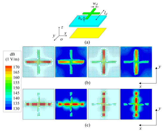
Figure 2.
Configuration and E-field distributions of the cross-shaped dielectric strip resonator in xoy-plane: (a) configuration; (b) TMδ1 mode; (c) TMδ3 mode.
Figure 3 shows that the magnitude of the electric fields distributed by TMδ1 mode along the x-axis and along the y-axis differs by 18 dB and the isolation of TMδ1 mode in the two mutually perpendicular directions is ensured. Similarly, TMδ3 mode along the x-axis and along the y-axis differs by 23 dB and the isolation of the TMδ3 mode in the two mutually perpendicular directions is ensured. As can be seen from Figure 3, when the horizontal dielectric strip resonator is motivated, the dielectric strip resonator in the vertical direction is not motivated.
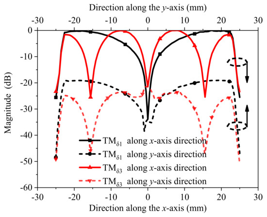
Figure 3.
The magnitude of the electric fields distributed by the TMδ1 and TMδ3 modes along the x-axis and along the y-axis.
As the proposed cross-shaped dielectric strip resonator meets the condition of the equivalent dielectric waveguide model, it can be analyzed as a dielectric waveguide model. When the electrical lengths are λg/2 and 3λg/2, the cross-shaped dielectric strip resonator resonates at TMδ1 mode and TMδ3 mode, respectively [27,28]. Therefore, the resonant frequency of TMδ1 mode or TMδ3 mode for the cross-shaped dielectric strip resonator can be calculated as follows:
where θ represents the electric size of the cross-shaped dielectric strip resonator, εreff = [(εr1 × hd) + (εr2 × hs1)]/(hd + hs1) is the effective relative permittivity of the proposed cross-shaped dielectric strip resonator, and βy and βz can be obtained [27] as:
where β0 is the propagation constant in the vacuum, and heff = hs1 + hd is the effective height of the proposed cross-shaped dielectric strip resonator. By combining Equations (1) and (3), the size parameter of the cross-shaped dielectric strip resonator can be obtained.
2.2. Dual-Mode Microstrip Resonator
Figure 4a shows a dual-mode microstrip resonator with open stubs loaded in the middle. On account of the symmetry of the structure, it can be analyzed through the even-odd-mode equivalent circuit [29,30]. When the resonator resonates in an odd mode, it is equivalent to an ideal electric wall along the symmetry plane of the resonator, and the odd-mode equivalent circuit shown in Figure 4b is obtained. The resonance conditions at this time are:
where c is the transmission velocity of the free-space wave, εr2 is the relative permittivity of substrate 2, and fodd is the odd-mode resonance frequency of the dual-mode microstrip resonator.
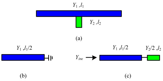
Figure 4.
Configuration of the dual-mode microstrip resonator: (a) configuration; (b) odd-mode circuit model; (c) even-mode circuit model.
Similarly, when the resonator resonates in the even mode, it is equivalent to an ideal magnetic wall along the symmetry plane of the resonator. The even mode equivalent circuit is shown in Figure 4c. The resonance conditions at this time are:
where feven is the even-mode resonance frequency of the dual-mode microstrip resonator. By combining Equations (4) and (5), the size parameter of the dual-mode microstrip resonator can be obtained for the resonant frequency requirements of odd and even mode.
2.3. Parametric Study of ls, ws, and lfs
Figure 5 depicts the effects of ls, ws, and lfs on antenna performance. It can be seen from Figure 5a,b that the bandwidth of two radiation bands increases, and the isolation between the two ports decreases with the increase in ls and ws. When the coupling strength between the cross-shaped dielectric strip resonator and the dual-mode microstrip resonator increases as ls and ws increase, the bandwidth of two radiation bands increases. However, the isolation between the different ports decreases because the spacing between paths via two ports decreases as ls and ws increase. Figure 5c exhibits that the isolation between the different ports decreases and the impedance matching improves with the increase in lfs. The isolation decreases because the spacing between paths via two ports decrease as lfs increases. The impedance matching improves because the feeding position becomes more suitable with the increase in lfs.
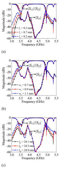
Figure 5.
The simulated performance variation with different parameters: (a) different ls; (b) different ws; (c) different lfs.
2.4. Design Procedure
The design guidelines of the dual-band, dual-polarized filtering antenna based on cross-shaped dielectric strip resonator are described below.
(1) On the basis of Equations (1) and (3), the initial dimensions of ld, wd, and hd can be calculated. The initial dimensions of l1, l2, Y1, and Y2 in the dual-mode microstrip resonators are obtained based on Equations (4) and (5), and then the initial values of w1 and w2 are obtained according to Y1 and Y2.
(2) According to the variation law in Figure 5a,b, the appropriate initial size of ls and ws can be obtained based on the required bandwidth and isolation.
(3) Finally, according to the variation law in Figure 5c, tuning the parameter lfs provides a good matching performance.
3. Results
Based on the above design process of the dual-band, dual-polarized filtering antenna based on a cross-shaped dielectric strip resonator, a prototype as shown in Figure 6a was fabricated and tested. Based on the above analysis, the specific sizes of the antenna were: l = 60 mm, w = 60 mm, ld = 45.5 mm, wd = 2.5 mm, hd = 3.9 mm, ls = 9.2 mm, ws = 0.9 mm, l1 = 26.2 mm, w1 = 0.3 mm, l2 = 5 mm, w2 = 2 mm, lf = 15.8 mm, lfs = 24.5 mm, hs1 = 0.913 mm, hs2 = 0.813 mm, h1 = 0.913 mm, and h2 = 0.813 mm.
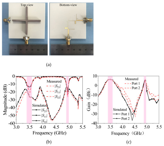
Figure 6.
Photographed, simulated, and measured results of the proposed antenna: (a) photograph; (b) |S21|, |S11| and |S22|; (c) gain.
Figure 6b,c shows the simulated and measured |S11| and gain of the prototype. The 10-dB impedance-matching bandwidths of two operating bands are 5.40% (at 3.5 GHz) and 2.03% (at 4.9 GHz), respectively. The measured gains in two bands are 6.4 dBi and 6.2 dBi, respectively. Two radiation nulls occur at 4.4 GHz and 5.1 GHz, respectively. The measured isolation between the two ports in the frequency band is greater than 20 dB and 16 dB, respectively. At the same time, it can be seen that the S-parameter curves and gain curves of the two ports are basically consistent, indicating that the two polarizations have good consistency.
The patterns of the E and H planes at 3.5 GHz and 4.9 GHz, respectively, when port 1 is excited are shown in Figure 7a,b. Figure 7a shows that when the antenna is operating at 3.5 GHz, the measured 3-dB beamwidths of the E- and H-plane patterns are approximately 77° and 78°, respectively. The cross-polarization level is also less than −19 dB within the 3-dB beamwidth of the E plane and less than −18 dB within the 3-dB beamwidth of the H plane. In the E and H planes, the front-to-back ratio is recorded at 21.7 dB and 22.7 dB, respectively. Figure 7b shows that when the antenna is operating at 4.9 GHz, the measured 3-dB beamwidths of the E- and H-plane patterns are approximately 53° and 49°, respectively. The cross-polarization level is also less than −14 dB within the 3-dB beamwidth of the E plane and less than −14 dB within the 3-dB beamwidth of the H plane. In the E and H plane, the front-to-back ratio is recorded at 10 dB and 19 dB, respectively.
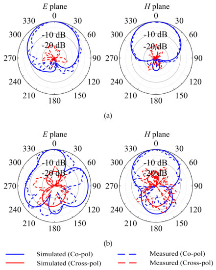
Figure 7.
Simulated and measured radiation patterns of the proposed design at excitation port 1: (a) at 3.5 GHz; (b) at 4.9 GHz.
Similarly, the patterns of the E and H planes at 3.5 GHz and 4.9 GHz, respectively, when port 2 is excited are shown in Figure 8a,b. Figure 8a shows that when the antenna is operating at 3.5 GHz, the measured 3-dB beamwidths of the E- and H-plane patterns are approximately 69° and 85°, respectively. The cross-polarization level is also less than −19.7 dB within the 3-dB beamwidth of the E plane and less than −18.3 dB within the 3-dB beamwidth of the H plane. In the E and H planes, the front-to-back ratio is recorded at 21.3 dB and 22.7 dB, respectively. Figure 8b shows that when the antenna is operating at 4.9 GHz, the measured 3-dB beamwidths of the E- and H-plane patterns are approximately 34° and 57°, respectively. The cross-polarization level is also less than −17.0 dB within the 3-dB beamwidth of the E plane and less than −18.4 dB within the 3-dB beamwidth of the H plane. In the E and H plane, the front-to-back ratio is recorded at 15.3 dB and 21.2 dB, respectively.
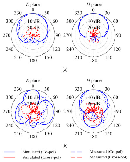
Figure 8.
Simulated and measured radiation patterns of the proposed design at excitation port 2: (a) at 3.5 GHz; (b) at 4.9 GHz.
The performances of the proposed work and the state-of-the-art works are summarized in Table 1. Contrasted with the dual-band, dual-polarized metal filtering antenna [13,16,17,18,19], the proposed antenna has the features of low conductor loss and higher design freedom. Contrasted with the dual-band filtering dielectric antennas [20,21,22,23], the proposed antenna not only has the function of dual-polarized radiation, but also has the advantage of a low profile.

Table 1.
The proposed antenna compared with other related works.
4. Conclusions
In this paper, a dual-band, dual-polarized filtering antenna based on a cross-shaped dielectric strip resonator is proposed. The dual-band filtering radiation function is realized by utilizing the odd and even modes of the stub-loaded microstrip resonator to excite the TMδ1 and TMδ3 modes in each polarization direction of the cross-shaped dielectric strip resonator. A prototype is fabricated and measured, which operates at 3.5 GHz and 4.9 GHz with the fractional bandwidths (FBW) of 5.40% and 2.03%, respectively, and the gains of these two bands are 6.4 dBi and 6.2 dBi, respectively. The two radiation nulls are located at 4.4 GHz and 5.1 GHz. Furthermore, the measured isolation between the two ports in the frequency band can achieve 16 dB. Contrasted with the state-of-art designs, the proposed antenna has all the considerations of dual-polarized radiation, low conductor loss, and a low profile.
Author Contributions
Conceptualization: L.J., J.S. and K.X.; methodology: L.J. and K.X.; software: L.J., H.T. and K.X.; validation: L.J., J.S. and K.X.; formal analysis: L.J. and K.X.; investigation: L.J., J.S. and K.X.; resources: L.J. and K.X.; data curation: L.J. and K.X.; writing—original draft preparation: L.J., H.T. and K.X.; writing—review and editing: L.J., L.L. and K.X.; visualization: L.J., J.S. and K.X.; supervision: J.S. and H.T.; project administration: L.J., L.L. and K.X.; funding acquisition: J.S. and K.X. All authors have read and agreed to the published version of the manuscript.
Funding
This work was supported by the National Natural Science Foundation of China (Grant 62201291), the Key Research and Development Program of Jiangsu Province of China (Grant BE2021013-1), the Natural Science Foundation of Jiangsu Province (Grant BK20200962), and the Natural Science Research Project of Jiangsu Higher Education Institutions (Grant 20KJB510004).
Data Availability Statement
The data presented in this study are available on request from the corresponding author.
Conflicts of Interest
The authors declare no conflict of interest.
References
- Qian, Y.-H.; Xie, S.-M. Wideband Circularly Polarized Filtering Hybrid Antenna. Appl. Sci. 2022, 12, 11018. [Google Scholar] [CrossRef]
- Hu, P.-F.; Pan, Y.-M.; Zhang, X.-Y.; Hu, B.-J. A compact quasi-isotropic dielectric resonator antenna with filtering response. IEEE Trans. Antennas Propag. 2019, 67, 1294–1299. [Google Scholar] [CrossRef]
- Hu, P.-F.; Pan, Y.-M.; Zhang, X.-Y.; Zheng, S.-Y. Broadband filtering dielectric resonator antenna with wide stopband. IEEE Trans. Antennas Propag. 2017, 65, 2079–2084. [Google Scholar] [CrossRef]
- Tong, C.-W.; Tang, H.; Li, J.; Yang, W.-W.; Chen, J.-X. Differentially coplanar-fed filtering dielectric resonator antenna for millimeter-wave application. IEEE Antennas Wirel. Propag. Lett. 2019, 18, 786–790. [Google Scholar] [CrossRef]
- Tang, H.; Tong, C.-W.; Chen, J.-X. Multifunction applications of substrate integrated waveguide cavity in dielectric resonator antennas and reconfigurable circuits. IEEE Trans. Antennas Propag. 2019, 67, 5700–5704. [Google Scholar] [CrossRef]
- Wang, X.-Y.; Tang, S.-C.; Shi, X.-F.; Chen, J.-X. A low-profile filtering antenna using slotted dense dielectric patch. IEEE Antennas Wirel. Propag. Lett. 2019, 18, 502–506. [Google Scholar] [CrossRef]
- Awan, W.A.; Hussain, N.; Kim, S.; Kim, N. A Frequency-Reconfigurable Filtenna for GSM, 4G-LTE, ISM, and 5G Sub-6 GHz Band Applications. Sensors 2022, 22, 5558. [Google Scholar] [CrossRef]
- Ji, S.-S.; Dong, Y.-D.; Fan, Y. Low-profile dual-band filtering antenna with a shared SIW cavity. IEEE Antennas Wirel. Propag. Lett. 2021, 20, 2053–2057. [Google Scholar] [CrossRef]
- Pan, Y.-M.; Hu, P.-F.; Leung, K.-W.; Zhang, X.-Y. Compact single- /dual-polarized filtering dielectric resonator antennas. IEEE Trans. Antennas Propag. 2018, 66, 4474–4484. [Google Scholar] [CrossRef]
- Tang, H.; Tong, C.; Chen, J.-X. Differential dual-polarized filtering dielectric resonator antenna. IEEE Trans. Antennas Propag. 2018, 66, 4298–4302. [Google Scholar] [CrossRef]
- Liu, J.-H.; Liu, H.-P.; Dou, X.-H.; Tang, Y.-K.; Zhang, C.; Wang, L.; Tang, R.-X.; Yin, Y.-Z. A low profile, dual-band, dual-polarized patch antenna with antenna-filter functions and its application in MIMO systems. IEEE Access 2021, 9, 101164–101171. [Google Scholar] [CrossRef]
- Liu, Y.-Y.; Zhang, X.-Y.; Yang, S.-J. Compact dual-band dual-polarized filtering antenna for 5G base station applications. In Proceedings of the 2020 International Symposium on Antennas and Propagation (ISAP), Osaka, Japan, 25–28 January 2021; pp. 791–792. [Google Scholar]
- Li, Y.; Zhao, Z.; Tang, Z.; Yin, Y. Differentially fed, dual-band dual-polarized filtering antenna with high selectivity for 5G sub-6 GHz base station applications. IEEE Trans. Antennas Propag. 2020, 68, 3231–3236. [Google Scholar] [CrossRef]
- Kahar, M.; Mandal, M.K. Dual-band dual-polarized SIW filtering antenna. In Proceedings of the 2019 International Symposium on Antennas and Propagation and USNC-URSI Radio Science Meeting, Atlanta, GA, USA, 7–12 July 2019; pp. 331–332. [Google Scholar]
- Xun, M.-Z.; Yang, W.-C.; Feng, W.-J.; Che, W.-Q.; Jin, H.-Y. Novel dual-polarized and closely dual-band filtering patch antenna array with good band-notched function. In Proceedings of the 2017 Sixth Asia-Pacific Conference on Antennas and Propagation (APCAP), Xi’an, China, 16–19 October 2017. [Google Scholar]
- Liu, Y.; Wang, S.-H.; Li, N.; Wang, J.-B.; Zhao, J. A compact dual-band dual-polarized antenna with filtering structures for Sub-6 GHz base station applications. IEEE Antennas Wirel. Propag. Lett. 2018, 17, 1764–1768. [Google Scholar] [CrossRef]
- Mao, C.-X.; Gao, S.; Wang, Y.; Luo, Q.; Chu, Q.-X. A shared-aperture dual-band dual-polarized filtering-antenna-array with improved frequency response. IEEE Trans. Antennas Propag. 2017, 65, 1836–1844. [Google Scholar] [CrossRef]
- Cao, Y.-F.; Zhang, X.-Y.; Xue, Q. compact shared-aperture dual-band dual-polarized array using filtering slot antenna and dual-function metasurface. IEEE Trans. Antennas Propag. 2022, 70, 1120–1131. [Google Scholar] [CrossRef]
- Lu, R.; Yu, C.; Zhu, Y.-W.; Xia, X.-Y.; Hong, W. Millimeter-wave dual-band dual-polarized SIW cavity-fed filtenna for 5G applications. IEEE Trans. Antennas Propag. 2022, 70, 10104–10112. [Google Scholar] [CrossRef]
- Wang, C.-Y.; Han, Z.-W.; Liu, H.-W.; Zhang, X.-Q.; Wang, L.-N. A dual-band filtering dielectric resonator antenna. In Proceedings of the 2020 Ninth Asia-Pacific Conference on Antennas and Propagation (APCAP), Xiamen, China, 4–7 August 2020. [Google Scholar]
- Liu, H.-W.; Tian, H.-L.; Du, C.; Huang, T.-T.; Zhao, Z.-Y.; Zhou, D. Dual-band filtering dielectric antenna using high-quality-factor Y3Al5O12 transparent dielectric ceramic. Adv. Eng. Mater. 2021, 23, 2100115. [Google Scholar] [CrossRef]
- Yang, Q.-L.; Pan, J. A dual-band filtering dielectric resonator antenna with high selectivity. In Proceedings of the 2021 International Applied Computational Electromagnetic Society (ACES-China) Symposium, Chengdu, China, 28–31 July 2021. [Google Scholar]
- Xu, K.; Jin, L.-X.; Tang, H.; Yang, W.-W.; Shi, J. A high-efficiency dual-band self-filtering antenna based on three dense dielectric strip resonators. IEEE Antennas Wirel. Propag. Lett. 2022, 21, 1532–1536. [Google Scholar] [CrossRef]
- Li, H.-C.; La, D.-S.; Zhang, C. Wide-/Dual-band omnidirectional dielectric resonator antenna with filtering function. In Proceedings of the 2021 Fourth International Conference on Electronic Information and Communication Technology (ICEICT), Xi’an, China, 18–20 August 2021. [Google Scholar]
- Naeem, U.; Bila, S.; Verdeyme, S.; Thévenot, M.; Monédière, T. A compact dual band filter-antenna subsystem for 802.11 Wi-Fi applications. In Proceedings of the Third European Wireless Technology Conference, Paris, France, 27–28 September 2019; pp. 181–184. [Google Scholar]
- Hu, P.-F.; Pan, Y.-M.; Leung, K.-W.; Zhang, X.-Y. Wide-/Dual-band omnidirectional filtering dielectric resonator antennas. IEEE Trans. Antennas Propag. 2018, 66, 2622–2627. [Google Scholar] [CrossRef]
- Rashidian, A.; Shafai, L.; Sobocinski, M.; Peräntie, J.; Juuti, J.; Jantunen, H. Printable planar dielectric waveguides based on high-permittivity films. IEEE Trans. Microw. Theory Tech. 2015, 63, 2720–2729. [Google Scholar] [CrossRef]
- Pozar, D.M. Microwave Engineering; Wiley: New York, NY, USA, 2006. [Google Scholar]
- Zhang, X.-Y.; Chen, J.-X.; Xue, Q.; Li, S.-M. Dual-band bandpass filters using stub-loaded resonators. IEEE Microw. Wirel. Compon. Lett. 2007, 17, 583–585. [Google Scholar] [CrossRef]
- Mao, C.-X.; Gao, S.; Wang, Y.; Qin, F.; Chu, Q.-X. Multimode resonator-fed dual-polarized antenna array with enhanced bandwidth and selectivity. IEEE Trans. Antennas Propag. 2015, 63, 5492–5499. [Google Scholar] [CrossRef]


Publisher’s Note: MDPI stays neutral with regard to jurisdictional claims in published maps and institutional affiliations. |
© 2022 by the authors. Licensee MDPI, Basel, Switzerland. This article is an open access article distributed under the terms and conditions of the Creative Commons Attribution (CC BY) license (https://creativecommons.org/licenses/by/4.0/).