1. Introduction
Micromachined flow sensors are one of the most successful devices in the MEMS industry. The first academic demonstration was presented by Putten and Middelhök in 1974. The sensor was built on a silicon substrate utilizing the anemometric sensing principle [
1]. However, the commercial realization of the micromachined flow sensor only took place more than ten years later by Honeywell with the calorimetric sensing approach [
2,
3]. In the past half a century, many research reports have been published on micromachined flow sensors. Summaries of these activities can be found in several review articles from different periods [
4,
5,
6,
7,
8,
9,
10,
11,
12,
13]. Different physical principles have been applied to fabricate the flow sensing devices in the laboratories, including differential pressure, Coriolis, optical, and magnetic sensing. The most common approaches are thermal mass flow sensing. There are no moving parts in the micromachined thermal mass flow sensors, the structure is relatively simple, and the process is readily achievable with the MEMS process capabilities in commercial foundries and laboratories alike.
In the past 40 years, commercialization of the MEMS flow sensor has progressed steadily. More than ten companies are now offering their proprietary MEMS flow sensors for various practical applications in automotive, medical, utility, instrumentation, automation, and many others. However, MEMS flow sensors have not been attractive products for market analysts of the MEMS industry [
14]. In many market reports of MEMS sensors, the value of the MEMS flow sensing products was either smaller than the actual size or was not considered as a market facilitator [
15]. One of the reasons could be that commercial MEMS flow sensing applications are very fragmented. The total market value is not easily accounted for. Many MEMS flow sensors are not shipped in the form of a packaged die but inside fully functional end products in which the cost of the flow sensor die is trivial. The performance of the MEMS flow sensor involves complicated fluidic dynamics and the control scheme’s impact is also great. Therefore, the exact market value of the micromachined flow sensors cannot be easily evaluated. Nonetheless, the market for MEMS flow sensors has been growing significantly since its inception. Today, the annual shipment of micromachined flow sensor dies is estimated to be over 25 million, and the products are dominated by the thermal mass flow sensing principle [
16]. Only a tiny percentage of the shipment of the products is based on Coriolis sensing principles [
17,
18,
19,
20,
21,
22,
23,
24]. The thermal mass flow sensors are manufactured with the calorimetric sensing principle, and anemometric sensors are relatively few. The micromachined Coriolis products apply only for microfluidics, and the shipment is currently limited due to the high cost. Some of the thermal mass flow sensor dies have been packaged for differential pressure measurements, and those are particularly successful in HVAC applications as the same pressure range offered by traditional pressure sensing products is of substantially higher costs.
There are three high-volume applications for the current MEMS thermal mass flow sensing products on the market. The first successful one was for automotive mass air flow sensors (MAF) applied for fuel-efficiency control starting in 1995 [
17]. In early 2000, applications in medical continuous positive airway pressure (CPAP) equipment [
24] and utility city natural gas meters [
25] also gained momentum and have been shipped in relatively high volumes since then. While MAF and CPAP applications do not require very high accuracy, and their working environments are relatively favorable, applications for utility natural gases have posed many challenges for the MEMS flow sensors. Utility gas meters are used for tariff purposes by city gas distributors, for which both precision and reliability are critical. Further, natural gases are mixed with different gases without a fixed composition. The gas composition variations will have a direct impact on the metrology precision of the calorimetric-based MEMS flow sensors. Another popular application is for medical equipment, particularly drug infusion-related equipment. It has been believed to be a potentially high-volume application for MEMS flow sensors, but the deployment is yet to be realized [
12]. Similarly, the ever-discussed applications in microfluidics are also challenged by the fragmented requirements and problems in fluidic composition issues. Calibration with actual fluids for many microfluidic applications is not feasible. Moreover, the current trend for flow measurement, where ever the flow sensor is applied, is to improve the precision while acquiring as much information as possible for better control of a process. These demands ask for innovations in micromachined flow sensing technology. In this paper, thermal time-of-flight sensing technology will be reviewed and discussed. This technology is relatively less popular in both research and commercialization. However, it offers the capability to address gas composition variations and self-calibration that the current calorimetric or anemometric technology is unable to offer. With more commercialized products becoming available, it could be the preferred one to overcome some of the current key market hurdles for the abrupt growth of the MEMS thermal flow sensing applications. This paper will review the thermal time-of-flight technology and the micromachined sensor process and operation. The summarized historical research work will show and address why micromachined sensors can be the enabler of this technology. This paper will also discuss the potential volume applications of this technology.
2. Thermal Time-of-Flight Sensing
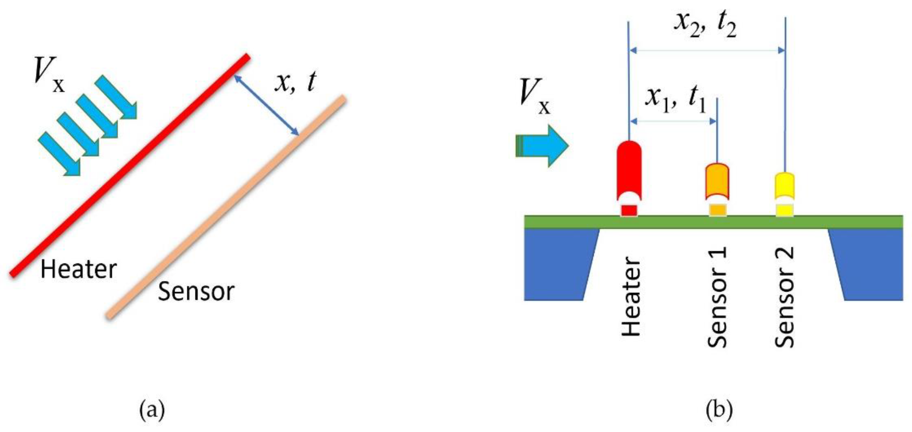
Figure 1 shows the sketch of the thermal time-of-flight sensors. The classic concept (a) has a heater wire and a sensor wire. It is also named a pulsed anemometer, while (b), a micromachined sensor, often has a microheater and multiple sensors that are made on a thermally isolated membrane on the silicon substrate. The thermal time-of-flight sensing concept can be traced back to the late 1940s by Kovasznay [
26]. A stationary hotwire was placed normal to the mean flow upstream of a movable sensing wire to measure the airflow in a wind tunnel. With the known hotwire driving frequency and comparing the sensing wire signal to the same, the spatial wavelength of the heat convection pattern was measured, and the air mean convection velocity was calculated. In recent years, quite a few excellent research works based on this concept have been published [
27,
28,
29,
30,
31,
32,
33,
34,
35]. In these studies, the approach was also named pulsed anemometers. It generally measures the heat transfer transient time as well as the responses at each sensing element with the hotwire being driven with various heat waveforms. Several sensing elements can be placed downstream of the “pulsed hotwire” or the heater. Although these studies have detailed measurement-associated issues such as diffusivity, pulsating, laminar, and turbulent flow, most works discussed high-speed turbulent flow applications. Compared to calorimetry and anemometry, the advantage of thermal time-of-flight is to measure additional parameters besides the flow rates. As the thermal response of each sensing element is dependent on the fluidic thermal properties, thermal conductivity and thermal diffusivity could be obtained via the simultaneously measured thermal response data. With these data, fluidic dependency could also be possibly removed. Further, the transient time domain data are much more immutable to the background interferences. Despite the advantages, there are also apparent drawbacks. For the packaged hotwire sensors into a flowmeter, the data acquired from these sensing elements are still dependent on the type of fluid that flows through the enclosed conduit because of the thermal response of the wire. This fluidic dependence makes it no different from the other thermal sensing principles. The hotwire operating with the thermal time-of-flight mode will not be able to be packaged into a shielded tube as the anemometers for protection because of its requirement for time resolution. Vapors, particles, and other fluidic conditions are always a challenge for the reliability of those free-standing wires in the flowing fluid. The traditional hotwire design is also complicated for the alignment of the wires at the installation. Vibration and rotation (yaw) add errors during operation. Another disadvantage is that the hotwire thermal time-of-flight sensors have a smaller dynamic range as the diffusivity dominates the heat transfer at the lower flow speed. At the high-speed regime, the precise measurement of the time domain data was difficult due to the stringent requirement for a precision time resolution, particularly in the earlier studies when the electronics were not advanced enough. For the hotwire time-of-flight, the sensor also behaved quite differently at laminar and turbulence, making the control algorithm very complicated. Moreover, the mass of the traditional hotwire lacks the speed of response necessary for applications such as medical devices that require high-speed flow rate measurements. These problems would then create barriers to the commercialization of this technology. Products utilizing thermal time-of-flight sensing are only very few. Medical respiratory flow sensors for ventilators and wind tunnel laboratory measurement devices [
36,
37] are two known applications on the market. The medical flow sensor in respiratory applications is no longer a choice for new devices. Attempt for a natural gas meter using the hotwire thermal time-of-flight mode was not successful, likely due to reliability and high-power consumption, even though excellent dynamic range and gas independence were reported [
38].
The heat wave propagation in the thermal time-of-flight sensing configuration observes the same physics for a thermal line source in a fluid. The total heat wave transfer includes both thermal diffusion and forced thermal convection, and the working principle can be expressed for energy conservation as below [
29,
33,
39,
40]:
where
T (K) is the fluidic temperature,
t (s) is the time,
k (W m
−1 K
−1) is thermal conductivity,
c (J kg
−1 K
−1) is thermal capacitance, and
ρ (kg m
−3) is the fluidic density. The heat wave
Q (J) is a time-dependent value of either a modulated heat wave or a defined heat pulse. Therefore, the fluidic flow speed
V (m s
−1) can be obtained by solving the above equation.
Apparently, for a static fluid, the flow speed will be null, and Equation (1) becomes
Some assumptions need to be applied to solve the above equations analytically. For a pulsed heat at the zero flow, the thermal diffusivity
α of the fluid will be [
39]:
Alternatively, if a modulated heat
is applied [
40]:
In either of these heat modulation approaches, once the velocity of the constant phase (
V0) is acquired at the static condition, the thermal diffusivity of the fluid can be obtained. The
x0 could be considered for the characteristic length of a known fluid within which the diffusion would be dominated, or it defines a low flow rate detection limitation. This is an obvious advantage for the thermal time-of-flight approach since the physical property of the fluid can be simultaneously measured. The calculated and measurement data agreed quite well per the studies [
41]. On the other hand, it could also be used to optimize the design for the distances between the heat source and sensing elements for a specific application.
According to the numerical and analytical study on the thermal time-of-flight sensor [
34], the time shift (time-of-flight) related to the flow velocity depends on both advection and convection shifts. The advection time shift is nearly proportional to the reciprocal of the flow velocity with some nonlinearity added by thermal diffusion. As the heat transfer coefficient is also proportional to the flow velocity, the convection time would be the reverse proportion to the flow velocity. Thermal convection time shift becomes insignificant when the flow velocity is very low. In addition, when the hot wire diameter decreases to several tens of micrometers, the effect of convection would also be negligible. Using a finite volume method, the study found that simulation data can match well to the analytical results of Equation (1) when the hot wire diameters are within a few tens of micrometers. Hence, at zero flow conditions, the measured time shift would be contributed by advection and kept as a constant or the fluid’s diffusivity can be measured accurately at this condition. These results also suggest that micromachined sensors would be more favorable compared to the traditional hot wires for a less complicated heat transfer since thermistors with micrometer dimensions are readily achievable with today’s micromachining process.
A one-dimensional approach could be applied for the micromachined sensors as the contributions from other dimensions would be very limited. This approach would also make the analytical solution easier, and the result of such can be expressed as [
39,
41]:
where
Q is the heat source, such as a pulsed signal, and
k is the thermal conductivity.
V is the averaged flow velocity and
α is the thermal diffusivity.
These analytical results also suggested that gas thermal properties can be extracted from the constants of the dynamic measurement data. On the other hand, if the sensor only has one modulated microheater and one sensing element for the measurement, the acquired data will still be dependent on the fluid thermal properties. Heat transfer will occur at the substrate. Diffusive spreading of the modulated heat signals, conduction via the boundary layer, and the intrinsic thermal responses of the sensing elements will all contribute to the measurement. Therefore, the value of a thermal time-of-flight approach would require additional sensing elements to remove fluid properties. Simple calibration with any accessible fluid, such as air or water, can be applied to measure other fluids without losing the metrology accuracy. Multiple sensing elements are readily achievable for the micromachined sensors, where the sensing element arrangement can be well defined with the photomasks that guarantee the desirable reproducibility. Assuming a micromachined sensor with two sensing elements, and the distances of these two sensing elements from the microheater are
x1 and
x2, respectively, solving Equation (5) can remove the fluid property-related parameters and obtain both the thermal diffusivity,
α, and fluidic property independent flow velocity,
V, as shown in Equations (6) and (7), respectively [
39,
41]:
where
t1 and
t2 are the heat transfer time recorded at the two sensing elements, respectively.
The differential temperatures between the sensing elements or amplitude data from each of the sensing elements can also be acquired simultaneously in addition to the time domain data. Therefore, the calorimetric or anemometric data can be measured at the same time. The calorimetric or anemometric data will provide a mass flow rate similar to the conventional calorimetric or anemometric approach per the data acquisition process. In the microfluidic flow measurement, the liquid is generally non-compressible, and the pressure effects of compressibility can be considered as secondary. Liquids have a much larger heat capacitance than gases, making the sensing element resistance-related temperature effects less pronounced. Moreover, most importantly, the dynamic measurement range can be substantially extended with the multiple sensing elements on a single chip. On the other hand, the pressure effects can be used to calculate the fluidic pressures for the gas flow measurement by correlating the time domain and amplitude data.
In the quasi-static situation, the cross-over flow velocity from the diffusion to time-of-flight could also be calculated in the one-dimensional approach, and Equation (3) could be used for the estimation.
Another advantage of the micromachined sensors over the traditional hot wire is the much lower power consumption or a lower temperature elevation in the fluid. External power injection is particularly sensitive for microfluidic applications where quite some liquid would be temperature-sensitive. For the micromachined sensors with a modulated microheater, the constant heating spot in the flow channel is avoided compared to a calorimetric sensor where the microheater could create a heating spot. Micromachined sensors are often made on a thermally isolated membrane with precise sensing element spacings, and with multiple sensing elements, and also extending the dynamic range. Commercial MEMS calorimetric flow sensors with membranes have demonstrated excellent reliability in many applications. In summary, the thermal time-of-flight sensor can measure mass flow, fluidic velocity, and fluidic properties, making the technology ideal for solving many issues in applications that the current MEMS calorimetric or anemometric sensor could not furnish.
3. Summary of Micromachined Thermal Time-of-Flight Sensors
It could be that the earlier research data for the pulsed hot wire anemometry and the more complicated control electronics, as well as the data processing scheme, make the thermal time-of-flight sensing technology less favorable for both commercialization and research alike. In the previous review articles for micromachined thermal flow sensors, thermal time-of-flight technology was only addressed briefly, or in some review articles, it is even completely excluded [
4,
5,
6,
7,
8,
9,
10].
Table 1 summarizes the literature on micromachined thermal time-of-flight sensors since 1986. Although the studies are few compared to those for MEMS calorimetric and anemometric flow sensors, some critical issues of the technologies have been well addressed in these papers. The aspects and results of each work are subsequently discussed.
The first micromachined thermal time-of-flight sensor on silicon could be the one reported in 1985 by Lambert and Harrington [
40] that targeted the application of automotive air-fuel efficiency. The authors believed the time difference measurement would relax many system accuracy constraints. The sensor was made on a silicon substrate coated with polyimide for thermal isolation. Lead (Pb) metal film with a line width of 39.4 µm was driven by a 154 Hz sinusoidal source to create the temperature oscillation, and lead telluride (PbTe) thermocouples located at about 150 µm from the micro heater were used for the detector. The sensor was packaged into a 6 mm diameter flow channel, and airflow of 0~250 g/s (~12,630 L/min) was measured. The study is particularly valuable by its detailed data on the effects of thermal isolation as the heat transfer takes place in both the flow medium and the sensor substrate. A proper sensor design would minimize heat transfer effects in the substrate. The thermal diffusivity of the medium, in which the heat transfers, determines the exponent decay rate of the modulated heat with distance. The experimental data presented in the study matched well with the theoretical model that the authors presented.
Stemme [
42] fabricated a CMOS sensor on a silicon beam with polyimide as the support and thermal isolation. The chip was heated by a pulsed modulated square wave resulting in electrical dissipation in two bipolar transistors. A diode measured temperature responses on the same chip. In an experiment for air flow measurement, the modulating temperature was switched from 96 to 146 °C above the air temperature. Moreover, the heating and cooling responses were recorded. The data fitted well with the theoretical predictions according to the oscillation differential equation of the sensor chip temperature. By examining the results for the airflow in the range of 2 to 30 m/s, the linearity of the output was better than the sensor operated with the differential temperature mode for the same sensor [
68].
Inspired by the success of a thermal time-of-flight sensor configurated with individual glass-encapsulated thermistors for microfluidics [
69,
70], Branebjerg et al. [
43] and Yang et al. [
44] fabricated a monolithic silicon flow sensor with a heating diode, a measurement diode, and a reference diode. The three diodes had the same size of 250 × 200 µm, and the distance between them was 1500 µm. The sensor was packaged into a liquid flow channel with a cross-section of 1500 µm square and operated at the thermal transit time mode with a frequency from 2 to 5 Hz. The sensor successfully detected 100 µL/min water flow with excellent stability and an estimated accuracy of 0.2% at the 200 µL/min. Compared to the individually encapsulated thermistors, the micromachined sensor had a significantly better dynamic performance by a factor of 90 (response time reduced to about 1 s from 90 s). However, the data also indicated that this sensor’s dynamic measurement range would be limited due to the weak signal at the low flow and the resolution issue at the high flow.
While developing a microflow device for microfluidics, a thermal time-of-flight sensor was fabricated to provide feedback to control the microvalve and pumps in the system [
45]. The sensor was made on a 0.2 mm silicon substrate composed of one microheater and three downstream sensing elements. These thermistors were made with platinum and had similar structures and electrical resistances. The thermistors were made on a diaphragm of the silicon oxide and silicon nitride membrane supported by a silicon frame heavily doped with boron for isolation and stress balance. The distances of these three thermistors from the microheater were 1.0, 4.2, and 10.2 mm, respectively. The data acquired from the three sensing thermistors could detect a gas flow speed of up to 5 m/s with singularity from the closest sensing element at about 4 m/s. There were about 10 times differences between the calculated and the measured flow speed by the sensor, but the authors did not offer an explanation.
Compared to the traditional pulsed wire anemometer, a micromachined anemometer was believed to have a better performance because of its better thermal response. A micromachined hot-wire anemometer was designed with a similar structure to a conventional counterpart. [
46] The sensing wire of the micromachined anemometer was made with heavily doped polysilicon, about 0.5 μm thick, 1 μm wide, and 10–160 μm long. In addition, a silicon beam and a thick Si handle were also made with the silicon wire. The Si beam was designed for a thermal and mechanical buffer between the supports and the handle to avoid interference with the flow. Like the traditional hot wire, the sensing wire was also made free standing to optimize the interaction with the flow and to minimize the thermal conduction to the handle of two parallel supports. Depending on the silicon wire length, a time constant of 5 to 50 µs, corresponding to a wire length of 10 to ~140 µm, could be achieved.
To solve the problem that an anemometric or calorimetric flow sensor is fluidic composition dependent or is unable to measure a mixed gas (H
2/N
2), the thermal time-of-flight sensor was developed to be placed together in parallel to an anemometric flow sensor [
47]. While an anemometric sensor outputs the signal related to the mixed gas composition, the thermal time-of-flight sensor would have additional time domain information. The authors indicated that the thermal time-of-flight sensor would not measure the gas-independent flow rate. However, they could apply an “artificial neural network” to obtain the desired results, although the detailed approach was not presented. To achieve the desired performance, the time-of-flight sensor made on silicon was a constituent of an array with as many as nine thermistors with a distance of 80µm between the thermistors. Each thermistor could be dynamically switched between the energy dissipating or anemometric and temperature-dependent resistive sensing function. Measurement of the different gas mixtures of helium and nitrogen showed a dynamic range within 10:1 could be achieved for a full scale of 20 mL/min in a flow channel of 250 × 1000 µm. In the paper, the authors also noticed that the thermal time-of-flight sensor was incapable of measuring of very low flow rate where the thermal diffusion dominated. With a similar sensor (spacing between the sensing elements was 100 µm with a length of 300 µm), the same research group further explored the thermal time-of-flight approach. The detailed theoretical explanations in this paper have been used for quite a few related research works. It revealed that the measurement principle could also be used to sense the thermal properties of the fluid, including thermal conductivity and thermal diffusivity [
39].
Ashauer et al. [
48] used a similar approach of dual sensors made of combined calorimetric and thermal time-of-flight elements to measure the microflow. However, the study is for the extension of the dynamic measurement range: a calorimetric sensor covered the low flow measurement while a thermal time-of-flight sensor was applied for high flow. A proper design of the two sensors and intelligent calibration must be applied to ensure a proper overlap of the two outputs. The micromachined sensor was made with polysilicon as the microheater, and thermocouples of polysilicon and gold were used as the sensing elements for both these two types of thermal sensors. The distance between the microheater and the thermocouples was much longer for the thermal time-of-flight sensor. These thermistors were placed on a very thin silicon nitride film for support and thermal isolation. It was estimated that the film was able to bear more than 1 bar pressure under stable conditions. With this approach, a dynamic range of 1500:1 was claimed. However, when applied to different fluids, the data showed the measurement was strongly dependent on fluidic properties at the low-flow calorimetric sensing regime and even for the data acquired at the lower flow rate from the thermal time-of-flight sensor. The dynamic range of the fluidic property-independent time-of-flight sensor would be limited to 3:1.
Instead of packaging separated calorimetric and thermal time-of-flight sensors into the same flow channel for additional measurement advantages, a sensor array was fabricated and operated at all thermal sensing modes of calorimetric, anemometric, and thermal time-of-flight sensing [
51,
71]. The sensor array was made with several equally spaced (500 µm) platinum wires on top of a parylene membrane, and the bottom side of the parylene was used as a cover to seal the microfluidic channel; hence, the sensor was considered to be “non-invasive” to the fluid under measurement. In the time-of-flight mode, a single pulse of 3 Vdc was applied to drive the micro heater (one of the thermistors in the array), and the data were taken from another thermistor 1 mm apart. The sensitivity of the sensing elements could be optimized for the pulse frequency. By comparison of the data for the three different thermal sensing modes, time-of-flight seems to require the highest power or incur a higher temperature elevation. At the same time, it would be less sensitive at the low flow. In addition, it had a smaller dynamic range with some nonlinearity in the data acquired. Another report [
60] confirmed the higher power when operating with the time-of-flight mode. Compared to the calorimetric mode, the time-of-flight mode could measure a much (2×) higher flow speed. The calorimetric and anemometric data in all these studies showed consistent results for their well-known characteristics. Dual-mode operation with both calorimetric and thermal time-of-flight on the same micromachined sensor was also applied for power saving [
56,
72]. In the study, germanium was used as the sensing thermistor, and chromium was made for the microheater and placed in the middle of the two-sensing thermistor with an equal distance of 675 µm, all on a silicon dioxide and silicon nitride-combined membranes for thermal isolation. This structure allowed for low-power consumption even for calorimetric mode at a maximum of about 5.4 mW (4 V, 1.35 mA) in constant heating. With the time-of-flight mode, the duty cycle can be extended for a steady flow, and power consumption of about 2 mW could be achieved. However, the authors also noticed that there would be a low flow end cutoff using time-of-flight mode due to the domination of thermal diffusion.
In an attempt to make the sensor more robust to contamination, a thick film thermal time-of-flight sensor was proposed [
49]. The sensor was made on an alumina substrate, and glass was used for thermal isolation. Pt/Au was screen-printed as the microheater, and either nickel or pyroelectric sensors (PZT) were also screen-printed. Compared with the micromachined silicon sensors, the thick film sensor was rather large with a dimension of 25 × 15 × 1 mm
3, and the sensor could have a size of 1.5 × 2 mm
2 with the sensor to microheater distance of about 5 mm. Although the report did not present the contamination-related reliability data, it showed an achievable full-scale accuracy of 2.5%. The sensor also had a much slower response of within 5 s and a power consumption of more than 2 W. This high-power consumption was undoubtedly unfavorable for some applications where the elevated temperature could impact the fluidic properties. Another work [
56] fabricated a silicon-based titanium/platinum sensing array for use with corrosive gas. The data showed that the thermal time-of-flight mode was comparably better for the rangeability with a millisecond response. Simulation on thermocouples with grounded stainless steel found that accurate measurement can be achieved with the time-of-flight mode and an auto-adaptive impulse response function [
73]. Therefore, a proper package would also be possible for the micromachined sensors to apply for the measurement in harsh environments.
Two-dimensional numerical simulations using ANSYS/FLOTRAN were compared to the experimental data from a surface micromachined thermal time-of-flight sensor [
52,
74]. The sensing elements were made of phosphorus-doped polysilicon, and the distances between the microheater and the sensing elements varied from 210 to 1038 µm. The sacrificial layer was made with PECVD oxide of about 1.2 µm. For the simulation, the heater was placed into a 1 mm diameter flow channel with a heater temperature of 200 K and a heating pulse width of 200 ms. The heat convection and conduction model were adapted from a previous publication [
75], where a quasi-static situation and temperature variation only confined to one dimension were assumed. It was likely that the heating or the elevated temperature in the tiny channel was too high. The best sensitivity was numerically and experimentally confirmed at the fastest distance in this study. In addition, the measurement data exhibited a constant positive deviation from the numerical data. It further had another positive deviation when compared to the theoretical calculations. Hariadi et al. [
50] noticed that for a micromachined CMOS thermal time-of-flight sensor operated at the pulsed mode, the device geometry, power level, and pulse characteristics would all impact the final device performance. A sensor with a single heater on a thermally isolated membrane and a diode on the silicon substrate was used to measure the fluid temperature. An approach with a model of the thermal boundary layer was used to decompose the heat transfer in the fluid and sensing element substrate. Based on the composite mode, the simulation was carried out using SPICE and analog hardware description language (HDL). The results indicated that a smaller pulse width would have a better resolution and a larger dynamic range. As an infinite pulse width would equal the constant power mode, the results indicated that the thermal time-of-flight mode could extend the dynamic range by properly selecting the pulse width compared to the data presented for the same sensor on a constant power anemometric mode [
76]. Another finding from this simulation was that the data were based on a monocrystalline silicon membrane of 5 µm thick with which the thermal time-of-flight mode could be well applied. Therefore, although the substrate heat transfer could impact the performance, a superior thermal isolation membrane (such as silicon nitride) would not be necessary for the device to be operated in thermal time-of-flight mode.
For many microfluidic applications where flow measurement is required, the micromachined thermal flow sensors are the first choice if the application is cost sensitive. With a proper adjustment of the circuitry, the same sensor could be applied for both gas and liquid. A report used the same thermal time-of-flight sensor for gas flow for a city natural gas flow meter prototype and a manifold-packaged microfluidic product for medical applications [
57]. The micro heater and sensing elements would be further thermally isolated for the gas flow sensing with open slots on both sides of these thermistors. However, the same could not be applied to liquid measurements. Therefore, if the sensor applies to both gas and liquid applications, there would be some thermal isolation sacrifice in the gas flow measurement. The reported data were acquired from a sensor with an asymmetrical design of the distance for the micro heater with respect to the up and downstream sensing elements of 200 and 250 µm, respectively. For this configuration, the outputs showed that the fitting was far different from the calculated theoretical values, although the measured data had good repeatability. This observation was likely due to the pronounced heat transfer via the membrane. The structure would also limit the applicable pressure to maintain an undeformed membrane flatness during the measurement. The data showed that the flow speed measured with the same sensor in the air could be 500 times higher than those in a microfluidic (water) medium, which was in agreement with the thermal property differences between air and water.
With the increasing research activities in microfluidics, applications of a micromachined thermal time-of-flight sensor were further explored. Berthet et al. [
58,
77] fabricated a glass/silicon/glass device using a bulk micromachining process for microfluidic application. In this study, the micromachined flow sensor was composed of a suspended heater and more than one sensing element across the microchannel with a dimension of 100 × 500 × 1000 µm. The structure had no membrane that reduced the unwanted heat transfer via the supporting membrane. The process was done with an SOI wafer, and the channel was formed via an anodic bonding of another glass wafer. While the data showed sequences of heat pulses and an estimated 5-degree elevation in temperature to ensure no impact on the fluidic properties, the heat dissipation from conduction via the channel wall would still take place, in particular for the signals acquired from sensing elements with a larger distance from the heater. However, with the differential measurement of two sensing elements at the different spaces from the heater, the imposed flow velocity can be linearly correlated to the measured velocity. The sensor also achieved a dynamic range of 1400:1. The authors proposed a phenomenological model and did computational fluid dynamics (CFD) simulations with the commercial software Ansys (FLOTRAN) and COMSOL. The analytical result for the temperature evolution in one dimension was slightly different from the previous results [
39,
41]. Although the fluid-independent analytical results were not explicitly presented, the experiment data did show that the differential measurements from two sensing elements could yield a similar correlation (6% deviations) between the imposed flow velocity and measured ones for water and hexadecane. These two liquids had a difference in diffusivity of 35%.
Since the thermal time-of-flight approach directly measures the time domain data of heat transfer and the distance between the heat source and the sensing element, which can be well-defined on a micromachined sensing chip, there would be a possibility that the flow speed can be calculated directly from the acquired data without the need for calibration, which is not possible for the other thermal flow sensing approaches. In practice, there will be other difficult factors that will affect the direct calculation or the measurement of a pure flow speed-related time difference. There is still hope that some correlation could be revealed once the other factors become a fixed constant or are measured beforehand. In a series of studies based on hotwire time-of-flight [
78,
79] for a calibration-free or self-calibration of a thermal time-of-flight sensor and comparison of experimental data on both air and water, it was found that the “calibration-free” thermal time-of-flight measurement principle needed to be combined with conventional anemometry. Further, the applicable rangeability was limited. Another claim of a micromachined sensor [
53,
80] with two conductive loops suggested that direct measurement of the electrical outputs of the pair could achieve a calibration-free flow speed measurement. However, the exact results were unknown, and any such products have not been seen on the market.
Cross-contamination is a big concern for many medical or food and beverage applications, and disposable products are greatly appreciated. With the potential of self-calibration and multiparameter detection capability, a cost-effective micromachining process was studied with the thermal time-of-flight sensing technology for microfluidic applications. The thermal time-of-flight sensor was fabricated using a screen-printing approach, in which the sensor had a silver micro heater and a downstream thermocouple that was composed of carbon black and silver particles. These sensing elements were made in a polymer mix on the glass substrate with a 3 mm space between the micro heater and the thermocouple [
63]. The heater was a 100 µm width meander. The sensor substrate was also used as the base of the microfluidic channel, which simplified the assembly and made the device very cost-effective. A drawback of this approach would be the prolonged time delay compared to the chips made on silicon with a much narrower line width for the micro heater. The slow time response could be an issue for some applications. Another low-cost fabrication approach [
66] of a microfluidic thermal time-of-flight sensor was made on multilayer low-temperature cofired ceramics with gold/platinum composite for microheater and negative temperature coefficient (NTC) materials for the other four thermistors. One thermistor was placed upstream to combine one of the other three downstream thermistors for calorimetric sensing for low flow rate detection, while the three thermistors were for a time-of-flight measurement. The data showed a much faster response than those in [
81], likely due to a better thermistor design, and the results fitted well with an empirical equation. However, the time delay was still longer than the sensors made on a thermally isolated substrate.
To reduce the power consumption and further improve the signal-to-noise ratio such that a better accuracy for the thermal time-of-flight sensing technology, sensors with heat emitting nano filament (100 × 1000 nm
2 in cross-section) and sensing nanowires with small pn-junctions (800 × 100 nm in cross-section) were proposed. The nano-heater to nanowire space was 6.5 µm, and the space between the nanowires of 1.9 µm was fabricated on the silicon substrate. Simulation indicated that up to 2 m/s nitrogen flow could be assessed, but no experimental test data were presented in the literature [
61,
82].
The capability to simultaneously measure fluidic flowrate and fluidic properties in thermal time-of-flight sensing technology has encouraged more research efforts. As discussed earlier, the results presented earlier [
39,
47] had not been convincing enough for a practical realization. Studies were also carried out for the static fluidic conditions to measure fluidic thermal properties alone. A micromachined calorimetric sensor was placed into various common liquids, the chromium microheater was driven by a sinusoidal heat wave, and data were collected for the amplitude of excess temperature (thermal conductivity) and phase shift (thermal diffusivity) against the frequency from 1 to 10 Hz. A 2-dimensional analytic model was used to assess the data acquired with a reasonable agreement between the measured and analytical ones [
54]. Using a similar sensor, the studies were extended for nitrogen gas, which also showed reasonably good agreement for the measured data and analytical model. For the gas measurement, a higher frequency scan was applied from 10 to 2 kHz, and data showed a better correlation below 400 Hz [
55]. The same approach was applied to measure the concentration of carbon dioxide and nitrogen mixed gas via the measured thermal properties [
59]. The measured phase shift had an excellent linear correlation to the carbon dioxide by up to 10% in volume percentage. The data also indicated that the measured diffusivity had a strong dependence on the micro heater driving frequency (results presented for a driving frequency from 70 to 140 Hz). This made the measurement procedure complicated as the measurement for different gases (nitrogen or carbon dioxide) would require a different driving frequency for better accuracy. Moreover, such a frequency could not be predetermined. In another study, a uniquely designed and micromachined sensor was composed of a germanium thermistor surrounded by four arc-like central heater elements made of chromium. The other four germanium thermistors were symmetrically located around the micro heaters. These thermistors were fabricated on a 1.4 µm thick, 1 mm wide silicon nitride/oxide diaphragm [
62,
83]. This structure enabled the authors to reveal in detail the heat transfer competition between diffusion and forced convection, both experimentally and theoretically. The data showed that the thermal conductivity of the fluid could be extracted via the velocity-independent temperature phase, which could be further applied for correction in the temperature amplitude for a “medium-independent” flow measurement. As such, it could serve similarly to the approach in [
59] to determine the concentration of a binary gas mixture. Some recent works [
64,
84] employed micromachined thin wires (2000 × 6 × 0.3 µm) suspended on a silicon trench of 2000 µm width and 300 µm deep. The micro heater wire was made of AuCr, and the sensing wire was made of Ni. This structure allowed the sensor to have a very fast response of 0.5 ms and relatively low power consumption. With the sensor operating at the pulse mode, thermal conductivities of methane-hydrogen mixture with several different concentrations correlated well with the thermal responses of the sensor, although the data could only be acquired at no-flow conditions. The measured velocity was still gas composition dependent, but the square root of the velocity was linearly correlated to the temperature. This observation was likely due to the sensor’s design, and the data at very low flow velocity was unavailable.
4. Micromachined Thermal Time-of-Flight Device Design, Fabrication, and Operation
4.1. Device Design Considerations
As summarized above, thermal time-of-flight sensing can be realized via quite different designs. There seemed not to be a preferred one among all the approaches reported. Ideally, the time-of-flight concept asks for an anemometer design in which the heater and sensor will have a small mass of negligible thermal responses to the medium and reach a true time-of-flight sensing independent of fluid compositions. Practically, such a design is not feasible. With micromachining approaches, the design and realization of the thermal time-of-flight device become closer to the ideal concept. Hence, it could be the ideal enabler of this technology. The unwanted effects of vibration, alignment, and yaw (rotational effects) in a traditional design could all be eliminated with the micromachined approaches. The thermal response of the elements and the supply power can also be significantly reduced, and the reliability can be much improved. These features significantly promote the feasibility of commercial products.
Because of the diversity of the applications, the design of the micromachined thermal time-of-flight sensor will be application dependent. Key parameters include the microheater and sensing element linewidth, the numbers of the sensing elements, and distances between the microheater and sensing elements. The linewidth will determine the thermal response. A narrower linewidth will help to have a faster response and less fluidic property-related response, but it will reduce the signal-to-noise ratio. It will also be limited by the input power of the specific applications. To achieve multi-parameter detection and take the advantage of the thermal time-of-flight measurement principle, the sensing elements downstream of the microheater should be at least two. The distances between the microheater and sensing elements will also be a consideration for the specific applications. A smaller distance will have less “time-of-flight” signals as thermal diffusivity will play a major role. A bigger distance will have stronger time-of-flight signals, but it will also require a higher heater power and will have a smaller dynamic range as the signals will quickly decay to lose the resolution for a reasonable data acquisition. The liquid applications will require much higher power than those for gases. However, for microfluidic applications, a high power would sometimes be detrimental as it could alter the fluidic properties. Therefore, the design needs to have a comprehensive consideration for a specific application. Thermal isolation should be another key parameter for the sensor design. For a micromachined sensor, a membrane is often used for thermal isolation. Open slots on the membrane near the microheater and sensing elements should be designed for gas flow applications. For liquid flow, alternative thermal isolation materials must be taken into account.
The sensing elements can be designed using one of the three common thermal sensing approaches, i.e., thermoresistive, thermoelectric, and thermoelectronic sensing. The schematic structures of these devices are shown in
Figure 2. Detailed discussions of these three sensing mechanisms can be found in the literature [
5,
7]. Thermoelectronic sensing design utilizes semiconductor junction diodes as the sensing elements, e.g., simple bipolar junction transistors. The process is CMOS compatible and easy to be fabricated in a miniaturized format. The temperature sensing mechanism is well understood, and its sensitivity could be easily tailored. However, its thermal isolation process would be relatively complicated, with the limitation of the thermal process control efficiency undefined. Furthermore, the subsequent calibration required great attention. These sensors mostly appeared in the earlier literature and are not the choice for commercial products.
Thermoelectric sensing, on the other hand, has several advantages. Its temperature sensing capability is offered by microfabricated thermopiles or multiple connected thermocouples with which a voltage will be generated when a temperature difference exists across the two ends of two connected dissimilar electrical conductors. Both connected ends of these conductors form an electrical junction. As the thermocouple can be made with doped polysilicon or CMOS-compatible metals, the thermoelectric sensors can also be fabricated via the CMOS-compatible process. With the state-of-the-art semiconductor process, a thermocouple’s size can be made much smaller. Therefore, in a fixed area, the number of thermocouples can be increased, or the sensitivity of the thermopiles can be significantly boosted. Because the thermopile is a thermal energy harvester, with proper thermal isolation and optimization, the common drifting problems associated with thermal sensing could be significantly reduced. Therefore, the resulting sensor can be very much desired for practical applications, particularly low-power applications. This sensing approach has been adopted by the design of many commercial MEMS calorimetric sensors. However, the design with multiple thermopiles would be more complicated for thermal time-of-flight sensing as thermopiles require both hot and cold junctions that limit the spacing design of any two sensing elements.
Thermoresistive sensors have merit for their simplicity in fabrication, and a broad spectrum of material selection is available for today’s commercial MEMS foundries. For a thermoresistive sensor, heat transfer or temperature variation will cause the resistance change of an electrical resistor because of its intrinsic temperature coefficient. Semiconductor materials such as doped polysilicon can also be used; hence, such sensors can be made with the CMOS-compatible process [
85]. The thermoresistive sensor can have a high sensitivity and good signal-to-noise ratio with the proper selection of materials. It is the technology for earlier commercial thermal calorimetric or anemometric sensing products. The structure of a thermoresistive sensing element allows it to be easily duplicated. Hence, this technology would be preferred for the thermal time-of-flight technology to realize its multiparameter capabilities with the multiple sensing elements. One of the disadvantages of the thermal time-of-flight sensor is that it is unable to acquire flow speed data for very low flow speeds where thermal diffusion dominates. For the desired sensor with a large dynamic range, a pair of thermistors can be placed close to the microheater and operated in the calorimetric mode for metering the low flow speed.
The spaces between the microheater and the sensing elements depend on a specific application with full-scale flow speed and power consumption consideration. The selection of the materials for the microheater and sensing elements would be more for the reliability and sensitivity requirements. For general-purpose applications, for example, the calorimetric sensing elements to the microheater should be anywhere from 5 to 60 µm, which will allow a measurement of approximately to cover 0.01 to 30 m/s for air. The final results will depend on the signal conditioning and control electronics as well as the algorithm for the data processing. Therefore, in the combined sensing application, the calorimetric sensing elements should be placed closer to the micro heater to have the highest sensitivity for low flow speed where the time-of-flight signal is more complicated to retrieve. The time-of-flight measurement spacing within 500 µm would satisfy most of the application requirements. For a simple design, two sensing elements should be placed downstream, and one additional sensing element could be placed upstream for flow direction identification or other functional requirements.
4.2. Fabrication
Figure 3 shows the schematic presentation of the cross-sections of the basic structure of the thermal time-of-flight sensors for liquid and gas, respectively. These sensors have simple structures and easy processes and typically involve five to six photomasks/lithograph steps. There will be no special equipment required for these processes. They could be readily done by the current state-of-the-art commercial MEMS device foundries anywhere in the world with a cost that would be even quite affordable for disposable applications. For the liquid application, if the pressure required during the measurement can be high (say, more than 1 bar (15 psi), the membrane structure would have reliability issues during the measurement since the excessive pressure could lead to a deformation of the membrane resulting in a change of the spacing between the micro heater and the other sensing elements. Hence, the thermal isolation cavity could be filled with porous materials [
86], or even a glass substrate could be employed.
The overall micromachining process is very straightforward. The membrane is usually made of silicon nitride on a silicon substrate with a thickness of about 1 µm. In the process of fabrication of the microheater and sensing elements, it will be dependent on which sensing principle will be taken. For example, for thermoresistive sensing, the thermistors can be deposited via e-beam evaporation or physical vapor sputtering deposition if metal thermistors are designed. For polysilicon thermistors, various doping technology can be used. After the thermistors are patterned, the metallization process would be the next step. For most designs, a thermistor close to the substrate and upstream of the flow will also be included for measurement of the fluidic temperature such that any temperature effects of the thermistors could be compensated. The surface passivation is also often made with silicon nitride or a mixture of silicon nitride and silicon dioxide with a total thickness of less than 1 µm. After the bonding pads are opened with plasmas etching, the backside thermal isolation cavity etch process will be followed via either depth reactive ion etching or wet chemical etching. Before the sensor singulation, the surface of the sensors would now go through additional surface passivation or conforming coating process to terminate the pinhole in the surface of the top silicon nitride film.
For microfluidic applications, some commercial approaches are to attach the chip outside a tiny thermally conductive tube; hence, a cavity would be helpful for thermal isolation and better performance. This “non-invasive” package is helpful for biological, biochemical, or other sensitive or high-pressure applications. However, the thermal barriers due to the tube wall would sometimes lead to drifting and limit the dynamic range of measurement. Although the sensor surface has the passivation layer that separates the sensing element and the liquid, there would be some challenges for the microfluidic device package in preventing the dead volume and any liquid contact with the chip’s carriers and the non-passivated areas on the chip after singulation.
For gas measurements, direct contact with the fluids is usually not a concern. However, the membrane structure would create issues for high-pressure applications or with an abrupt gas pressure alternation. To solve this problem, the sensor membrane is often designed with some “open features” that allow the gas to quickly access the cavity underneath the membrane, leading to a quick pressure balance for the membrane. The openings are usually placed around the micro heater and the sensing elements as they can serve as additional thermal isolation. These “open membrane” designs could sometimes not be allowed in a CMOS-compatible process. Then, some package structures could be designed to allow gas access to the backside cavity. The advanced MEMS process now offers the chip VIA process that can reduce the chip size and reduce chip cost. The VIA structure will also simplify the sensor package process and enhance reliability, as the wire bonding process can be eliminated.
4.3. Device Operation and Data Process
Figure 4 shows the block diagram for the basic components of a complete functional thermal time-of-flight sensor. Compared with the other thermal sensors, the critical difference for the thermal time-of-flight sensor is that the microheater is driven by modulated heat, and measurement from the sensor would require both time domain data and analog data (amplitude or temperature deviations). For heater modulation, the most frequently used approaches in the literature are pulse, square wave, and sinusoidal wave. With the current electronics, such modulation is very easy to realize via an MCU and an amplifier. In some MCUs, amplifiers are already integrated; hence, one high-performance MCU alone can create the modulation. The pulsed or square wave (extended pulse becomes DC when pulse time is further extended) would be simple. However, a sinusoidal wave will generate much better resolution or yield better measurement accuracy. The measured “time-of-flight” from a micromachined sensor would be in microseconds. The data stream would require the MCU to have a better source for the data process than a typical calorimetric measurement. The time-of-flight or phase shift can also be measured via a pure hardware demodulator. Unless only analog output is required, the digital data process will also require high-resolution ADCs of at least 16 bits to have the desired accuracy. To maximize the benefit of the thermal time-of-flight sensing technology, data should be acquired from at least two sensing elements for multiparameter acquisition and fluidic property-independent measurement. Similar to all thermal sensing technology, measurement of the fluidic temperature is also very important for the temperature compensation of the control scheme. The typical frequency spectrum of heater response and signals acquired from these sensing elements are shown in
Figure 5, where a 100 Hz driving sinusoidal modulation was applied, and the sensor was a silicon nitride membrane-based gas sensor [
57]. It should be noted that the driving frequency for the micro heater should not be close to the harmonics of local city electricity. These wanted harmonics can be filtered out easily with demodulation applied in the data measurement.
Selecting a proper driving frequency would be essential, depending on the applications and sensor design. A fast-driving frequency may have less interference, but the signal-to-noise ratio could not be satisfied. It would be helpful to perform a frequency scan before finalizing the circuitry design to determine the optimized frequency. It would be instrumental in designing a single sensor for applications of multi-fluidic or mixed fluidic measurements [
59]. For a general-purpose measurement, a frequency below 100 Hz would be recommended, with the exclusion of those applied for local city electricity, which will inevitably be shown in the spectra but can be easily filtered out in the data processing. The data processing and subsequent calculation of the phase shift or the corresponding heat transfer time from the flowing fluid at a specific speed could be done with either a hardware demodulator or software. Some commercially available pre-phase-lag detectors with precision lock-in amplification technology can be used for the signal conditioning circuitry. The time domain data is usually more stable and have less drift compared to analog calorimetric or anemometric temperature data acquisition scheme.
Figure 6 shows the acquired data from the calibration of a time-of-flight sensor for microfluidic applications. The sensor had a microheater and two thermistors as the sensing elements placed at a distance of 260 and 110 µm from the microheater. All the elements were made of platinum with a linewidth of 4 µm. The microfluidic channel had a cross-section of 2.0 × 0.5 mm. The sensor was calibrated with purified water using a high-precision syringe pump together with a high-precision balance. Detailed information can be found in a previous paper [
67]. The output phase shifts were plotted in a polar plot in
Figure 6a. The reference flow rate against the phase shifts is shown in
Figure 6b. The polar plat would provide important information for the performance of the sensor, and they are a direct presentation of the relative phase shift and the smoothness of the data output (calibration data acquisition errors or any system errors). It could also help the examination of the offset information, particularly for multiple sensing elements. The relative shifts would be more straightforward for visual scrutinization. On the other hand, the calibration curve would be critical for the data processing and the device’s accuracy performance. The calibration curve shows a non-monotonic transition at the low flow rate regime where thermal diffusion dominates. In the theoretical approximation, the offset would be a measure of the fluidic diffusivity, as shown in Equation (3). If the theory holds, the offset should be a constant independent of the relative distances between the sensing elements and the micro heater. The measured data shown in
Figure 6b, however, indicated the offset strongly depends on such a distance, and the closer distance has a smaller offset. The results suggested that there would be multiple heat transfer paths in the practical case. For the data presented in
Figure 6, the thermistors were made on the silicon nitride membrane. Since silicon nitride’s thermal diffusivity is larger than that of water [
87], the heat transfer process would be a combined heat transfer via both water and silicon nitride. These differences could explain that the observed data that has a larger space between the microheater and the sensing elements would have a bigger offset or effective diffusivity using the two-phase heat transfer model [
88]. The results could also be used as a guideline for the sensing element spacing design for applications if the thermal property measurement is also needed. The transition from the diffusion-dominated regime to the time-of-flight regime could also be estimated with the model discussed in the literature [
75]. Within this regime, the “effective time” increased with the flow speed, as it would be the three or four heat transfer paths lapped together, i.e., diffusion in the fluid, diffusion in the substrate, flow speed contributions, and possibly some effects from the diffusion at the channel walls, as in the case of microfluidic applications.
Thermal time-of-flight sensors can obtain calorimetric or anemometric data and time domain data at the same time. The microheater and sensing elements’ temperature differences or amplitude changes can be measured using the classic calorimetric or anemometric sensing circuitry.
Figure 7 shows the calorimetric data (a) and time-of-flight data (b) from the same sensor discussed above. The fact that the calorimetric data can also be measured is undoubtedly an advantage over pure calorimetric sensing as the additional data would provide much more information, including mass flowrate, flow speed, or volumetric flow rate via a calibration procedure. Additionally, the measured time can be used to calculate the flow speed since the distances are well-defined. This feature can potentially be used for the development of the self-calibration scheme. At zero flow, the thermal diffusivity can be measured as discussed above, while thermal conductivity could also be directly measured using the microheater’s thermal (power) consumption value. With all these data, the measurement accuracy could be cross-referenced and supported for monitoring the sensor reliability performance. A well-designed thermal time-of-flight sensor would require a careful examination of all these factors, as the spacings and numbers of the sensing elements would be all critical for the data being acquired. For example, the spacings between the microheater and sensing elements on a micromachined thermal time-of-flight sensor usually are much larger than those used for calorimetric or anemometric sensors. The thermal time-of-flight signal will be more pronounced outside the diffusivity regime. The smaller spacing for calorimetric sensing will allow a better signal-to-noise ratio and data linearity. Therefore, in this respect, thermal time-of-flight sensing would require a low flow rate compensation. This issue needs to be solved at the device level design. If the low flow speed cannot be deconvoluted from the diffusion-dominated signal, a calorimetric element could be added to gain the dynamic range. This aspect will be further addressed in the following section for applications.
One advantage of thermal time-of-flight sensing is that the data can be fitted with an empirical formula based on the theoretical models. For the data shown in
Figure 7, the fitting from these two sensing elements could be done with a single formula, close to that proposed in [
66].
where
A,
B,
C,
D, and
E are fitting constants.
The empirical formula would allow the measurement to be more accurate than the calorimetric or anemometric measurement, where the data linearization would not usually be done via an analytical model.
6. Concluding Remarks
Among the micromachined commercial thermal sensing devices, thermal time-of-flight is less popular. One reason could be rooted in the fact that the early commercially successful thermal flow sensing products were either made with hotwire anemometry or capillary calorimetry. The traditional hot wire thermal time-of-flight sensor does not have any competitive advantage. It is still fluidic composition-dependent. Further, it suffers from slow response, low flow speed insensitivity, and small dynamic range. It also has more troubles during installation, and the tiny wire does not guarantee reliability for many applications. The only attractive feature would be its capability in turbulence flow measurement. The electronics were less advanced when the micromachined thermal flow sensor was commercialized in the 1980s. The earlier products were mostly made with analog circuitries. All these factors would not encourage the commercialization of thermal time-of-flight sensing products. However, today’s electronics have no comparison with those in the 1980s, and they offer many more options for the signal process at a very low cost. Furthermore, the micromachining process capability and package advancement could change the landscape for the technology. The current issues with commercial thermal flow sensing products have also been a driving force in identifying pathways for innovation of the technology.
Since the micromachined thermal sensing technology was incepted, the research activities on the thermal time-of-flight sensing approaches have been far less than those for calorimetric and anemometric sensing technologies. As we have discussed above, many drawbacks of classical thermal time-of-flight sensing could be eliminated with the advanced micromachining process and state-of-the-art electronics. These include fluidic property independent measurement, simultaneous fluidic thermal property or relative fluidic concentration data, small signal capability, and higher accuracy in turbulence flow. In particular, the possibility of self-calibration and self-diagnosis for reliability can not only substantially reduce costs but would also be indispensable for some biotech and medical applications. Compared to the current calorimetric or anemometric micromachined sensors, reliability is another factor that thermal time-of-flight sensor could offer some additional benefits, although the weakness of a membrane design could not be performing in a fluid that is not clean and has abrupt external pressure changes or other situations that could damage the membrane. Thermal time-of-flight can measure both the time domain and amplitude or calorimetric data which could be used for cross-correlation when the sensing element surfaces have light contamination or even surface deposition. If the changes in surface conditions take place, the thermal time-of-flight sensor could send the alarm or cancel out such changes with signals from multiple sensing elements when such changes are not extremely localized. This cross-correlation feature is very helpful for sensor reliability, in particular for long-term performance.
Among the foreseeable disadvantages, power consumption could be a major challenge as the algorithm will require much more computing power to obtain the desired results, and the thermal time-of-flight sensors might not readily adapt to some of the current effective low-power designs in calorimetric sensors. Another disadvantage is that thermal time-of-flight sensing intrinsically has a smaller dynamic range, and more physical parameters are involved in the data processing. However, these could be amended via additional sensing elements and a more intelligent flow channel design. More work is surely needed to explore the low flow speed regime so that better performance can be made available for some applications. It is believed that with more effort, thermal time-of-flight sensing technology could lead the abrupt growth in various applications of micromachined thermal sensing devices.


