Abstract
The piezoelectric inkjet printing technique has been commonly used to produce conductive graphics. In this paper, a trapezoidal waveform design method for squeeze-type piezoelectric inkjet printhead is presented to provide a modified steady ejection and optimal droplet shape, in which a coupled multi-physics model of a piezoelectric inkjet printhead is developed. This research describes the effects of parameters, including rising time tr, falling time tf, and dwelling time td, of the trapezoidal waveform on the pressure at the nozzle through numerical simulations. These parameters are initially optimized based on numerical simulations and further optimized based on experimental results. When the printhead is actuated by the optimized waveform with the tr = 5 µs, td = 10 µs, and tf = 2 µs, the droplets are in optimal shape, and their size is about half the diameter of the nozzle. The experimental results validate the efficacy of this waveform design method, which combines numerical simulation and experiment, as well as demonstrating that ink droplet formation can be studied from the point of pressure variation at the nozzle.
1. Introduction
Piezoelectric inkjet printing is a technology that uses piezoelectric inkjet print heads to deposit droplets on substrates and form graphics, and it has been widely used for printing patterns and documents [1]. Piezoelectric inkjet printheads not only have a strong control ability for droplets and high printing accuracy, but also need no heating, so they have more flexibility in ink compatibility [2]. Based on these features, many efforts have been made to use piezoelectric inkjet printing technology to directly deposit functional materials, thus expanding the application areas of piezoelectric inkjet printing technology. For example, piezoelectric inkjet printheads are used as manufacturing tools for printed electronics, and various types of conductive graphics are prepared using conductive inks containing effective particles [3]. This contributes to the fabrication of flexible electronics such as conformal antennas [4], wearable electronic devices [5,6], and biosensors [7].
With the expansion of piezoelectric printing applications, piezoelectric printing technology with higher accuracy is highly desired. For example, conformal antennas require ink droplet diameters down to the micron level [4]. Printing accuracy is affected by fluid characteristics, the print head structure, and even the actuating waveform [8]. During ejection, the piezoelectric inkjet printheads provide ink to the nozzle, while an actuating waveform is applied to the piezoelectric actuator to form a pressure wave. The pressure wave is propagated and reflected to generate droplets at the nozzle for ejection [9]. In the above process, the actuating waveform directly affects the velocity of the droplets, the ligament length, and the generation of satellite droplets [10]. Therefore, the actuating waveform can be optimized to improve the printing accuracy.
Based on Dijksman’s book, the trapezoidal waveform has strong controllability, large amplitude, and strong driving capability. This is also the reason why it was chosen as the actuating waveform of the printhead. At present, trapezoidal waves are widely used to actuate piezoelectric inkjet printheads. They include four parameters: rising time tr, falling time tf, dwelling time td, and voltage amplitude U [11]. There have been several studies on the effect of trapezoidal waves on injection performance: the effect of the trapezoidal waveform on droplet volume and velocity in a bend-type piezoelectric inkjet printhead is discussed in [2]; the effect of the trapezoidal waveform on droplet morphology in squeeze-type piezoelectric inkjet printheads is investigated in [12]; and the effect of waveform parameters on droplet formation is discussed in [13] using numerical simulations and experiments. Therefore, the trapezoidal waveform needs to be properly designed to promote the piezoelectric inkjet printheads to generate droplets with optimal shape.
Most of earlier research focused on optimizing the U and td of trapezoidal waveforms: a droplet-monitoring system is designed in [10] to record the droplet formation. It adjusts the U and td in real-time so that the printhead can eject continuously. In [11], td in the trapezoidal waveform is optimized by observing and measuring the motion of the meniscus at the nozzle to achieve high-speed ejection. This method enables the fast optimization of trapezoidal waveform parameters. Xiao et al. used Doppler vibrometry to determine tr and tf in the waveform and optimized td by numerical simulation in [14]. This study demonstrates that this method can speed up the design efficiency of bend-type piezoelectric inkjet printhead structures.
The trapezoidal waveform design method for squeeze-type piezoelectric inkjet printheads is mainly optimized for the U and td, ignoring the effects of tr and tf on the ejection. The tr and tf need to be precisely optimized by suitable methods to generate droplets with the optimal shape for a higher printing accuracy.
This paper proposes a waveform design method for squeeze-type piezoelectric inkjet printhead based on a numerical simulation and experiment. First, the coupled multi-physics field simulation software COMSOL Multiphysics is used for the preliminary design of the tr, tf, and td of the trapezoidal waveform. Simulation results are compared to determine the optimal parameters and to analyze the effect of these parameters on pressure at the nozzle and droplet morphology. Then, a high-speed CCD camera with a microscope is used to observe the droplet formation to verify the simulation results. The parameters are further optimized according to the differences between the experiment and simulation. Actuated by the optimized waveform, the printhead can generate droplets with optimal shape. The droplet diameter, in this case, is about half the diameter of the nozzle, which is beneficial for improving printing accuracy.
2. Numerical Simulations
The commonly used piezoelectric inkjet printheads include squeeze-type, shear-type, bend-type, and push-type [15]. Squeeze-type single-nozzle printheads have a stronger jetting force than that of the commercially available multi-nozzle inkjet printhead. As a result, a wider range of ink can be jetted, and it is commonly used in ejection evaluation experiments to determine the optimal printing parameters [16]. Figure 1 shows the structure of the squeeze-type piezoelectric inkjet printhead (MJ-AT, Microfab, Plano, TX, USA) utilized in this study. The printhead length is 22.86 mm, the nozzle radius is 30 µm, and the taper angle at the nozzle is 15°. The printhead consists of a glass capillary tube with an actuated piezoelectric part adhered to the outside of the glass capillary tube [17]. The appropriate ink viscosity is an important guarantee of printing accuracy. The phenomenon of clogging can occur when viscosity is too high, while the contrary is a strong liquidity, resulting in unclear imaging. The test ink is nano-silver conductive ink (Jet-600C, HS Electronics) with a density of 0.95 g/cm3, viscosity of 6 mPa·s, and surface-tension coefficient of 27 mN/m. That satisfies the technical parameters of the piezo printhead. In an ejection, the actuating waveform is applied to the actuated piezoelectric part. The outer surface is connected to the positive electrode, and the inverse piezoelectric effect causes the piezoelectric part to expand and contract, eventually generating droplets.
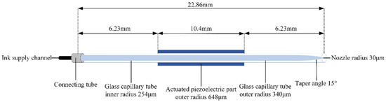
Figure 1.
Schematic of squeeze-type piezoelectric inkjet printhead.
The ejection of the piezoelectric inkjet printhead is numerically simulated using the commercial finite element analysis program COMSOL Multiphysics. As shown in Figure 2, the simulation model is coupled with a piezoelectric effect, fluid–structure interaction, and the two-phase flow (level set). The piezoelectric part is designed as a movable object. The fluid–structure interaction is bi-directional and real-time boundary data are transferred between the two physical fields. The moving mesh method is used to deal with the large-size deformation of solid structures and the construction of fluid–structure coupled interfaces. A fixed negative pressure boundary condition (800 Pa) at the ink supply channel is adopted to eliminate the effect of gravity on the ink. The numerical model uses adaptive mesh refinement to improve the accuracy of the simulation.
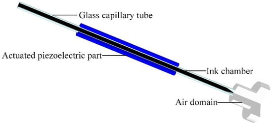
Figure 2.
Numerical simulation model built in COMSOL Multiphysics.
According to fluid dynamics theory, the incompressible N-S equation containing surface tension is used to describe the relationship between mass and momentum of the fluid.
where ρ is the fluid density; v is the velocity vector of fluid flow; ∆ is the Hamiltonian operator; p is the pressure; µ is the fluid viscosity; and F is the volume force. The effect of surface tension on the injection process was not explicitly given in the text, but has now been supplemented in Chapter 2 as follows.
In order to obtain the accurate velocity of ink droplets, the effect of surface tension on ink droplet jetting must be considered, and the continuum surface force (CSF) model is used in this paper.
where σ is the surface tension coefficient; δ is the interface Dirac delta function, which is non-zero only at the fluid interface; κ is the interface curvature; and n is the interface unit normal vector.
The κ and n can be expressed according to the level-set function as
To simplify the calculation of surface tension, the δ function is approximated as
There is a two-phase flow consisting of gas and liquid in the mode. The fluid interface between two immiscible fluids needs to be tracked in the numerical simulation. In this paper, the level-set method with reinitialization is used to track the two-phase flow interface, and the convective transport equation of this method is:
where ϕ is the level-set variable; γ is the mobility; ε is the parameter-controlling interface thickness.
3. Preliminary Design of Trapezoidal Waveform Parameters
The finite element analysis software COMSOL is used to preliminarily optimize the trapezoidal waveform parameters considering the pressure variation at the nozzle. These parameters include rising time (tr), falling time (tf), and dwelling time (td).
3.1. Optimization of tr Based on the Pressure at the Nozzle and Meniscus Motion
The waveform shown in Figure 3 is designed to optimize the tr. Different voltage amplitudes will certainly affect the choice of waveform parameters [12]. However, it is confirmed that each piezoelectric nozzle has a range of applicable voltage–amplitude parameters. The voltage amplitude of 40 V was selected as the experimental parameter of the piezoelectric nozzle after referring to the manual of the piezoelectric nozzle. The tr and td in the waveform are set to tr + td = 50 µs. During the tr, the piezoelectric part expands, thereby creating a negative pressure in the chamber. This negative pressure causes the ink to be sucked back into the nozzle, while the ink is sucked into the chamber at the ink supply channel. Excessive ink suck-back is not conducive to droplet generation, as shown in Figure 4.
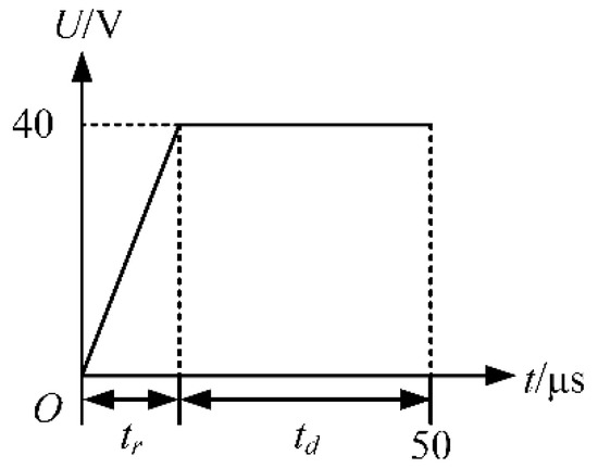
Figure 3.
Waveform used in the optimization of tr.
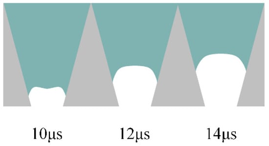
Figure 4.
Excessive ink is sucked into the nozzle when the tr is 1 µs.
Hence, the negative pressure at the nozzle should be as small as possible to prevent excessive ink from being sucked into the nozzle. The tr is optimized by comparing the pressure variation at the nozzle at different tr, as shown in Figure 5. The shape of the pressure curve at the nozzle is similar at different tr. As the tr increases, the pressure variation at the nozzle and the maximum negative pressure decrease. According to the pressure wave propagation theory, the pressure wave generated during the tr is continuously propagated and reflected in the chamber [9]. Therefore, small droplets may be generated in the absence of positive pressure waves generated during the tf. If the td is not set properly, the pressure waves generated during the tr and tf are propagated and reflected separately in the chamber, making it very easy to generate satellite droplets.
Figure 5.
Effect of tr on the pressure at the nozzle.
Therefore, the tr is optimized by comparing the simulation results of the meniscus motion at the nozzle at different tr, as shown in Figure 6. When the tr is 5 µs, the motion of the meniscus at the nozzle is so small that the printhead cannot easily generate satellite droplets. In summary, the optimal tr value is initially determined to be 5 µs.
Figure 6.
Simulation results of meniscus motion at the nozzle when the tr is 4 µs and 5 µs.
3.2. Optimization of tf Based on the Pressure at the Nozzle
The tf is optimized using a trapezoidal wave with a large value of td as shown in Figure 7. The effect of the large value of td is to make the pressure wave generated during the tr propagate and reflect continuously in the chamber. The falling edge of the voltage is applied to the printhead after the decay of this pressure wave. U is set to 40 V. To minimize the effect of the tr on the pressure at the nozzle, the tr is set to 5 µs according to the simulation results above. The td is set to 95 µs, which means that the falling edge of the voltage is applied to the printhead at 100 µs. During the tf, the piezoelectric part contracts, thereby creating a positive pressure in the chamber. As the positive pressure increases, the ink is squeezed out of the chamber to form a ligament, as shown in Figure 8.
Figure 7.
Trapezoidal waveform with a large value of td.
Figure 8.
Ink is squeezed out of the chamber to form a ligament when the tf is 1 µs.
Ideally, this positive pressure is superimposed with the reflected positive pressure of the pressure wave generated during the tr, causing the positive pressure at the nozzle to increase. The droplets are squeezed out of the chamber under this positive pressure. To eject droplets, the positive pressure at the nozzle needs to be as high as possible. The tf is optimized by comparing the pressure variation at the nozzle at different tf, as shown in Figure 9. The shape of the pressure curve at the nozzle is similar at different tf. As the tf increases, the pressure variation at the nozzle and the maximum positive pressure decrease. Hence, the optimal tf value is initially determined to be 1 µs in order to generate a large positive pressure.
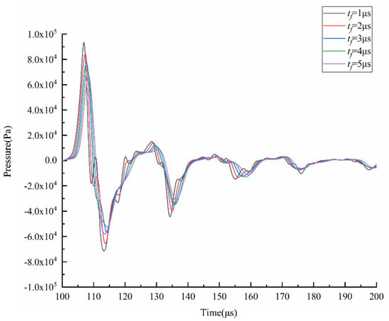
Figure 9.
Effect of tf on the pressure at the nozzle.
3.3. Optimization of td Based on the Pressure at the Nozzle and Droplet Formation
The td is optimized using a trapezoidal waveform with different td, as shown in Figure 10. The waveform parameters are set as follows: tr = 5 µs, tf = 1 µs, U = 40 V. According to the pressure wave propagation theory, the optimal td is to make the positive pressure generated during the tf, and the positive pressure obtained by reflection superimposed in the middle of the chamber generates droplets with an optimal shape. For this purpose, a sufficient pressure variation at the nozzle is required. The td is optimized by comparing the pressure variation and velocity variation at the nozzle at different td, as shown in Figure 11 and Figure 12. The shape of the pressure curve at the nozzle is distinctly different at different td. When the td is 5 µs, both the maximum positive pressure and the maximum negative pressure are large, resulting in a large pressure variation. When the td is in the range of 10~20 µs, the maximum positive pressure and the maximum negative pressure are appropriate, making the pressure variation moderate. When the td is longer than 20 µs, the maximum positive pressure and the maximum negative pressure are small, so the pressure variation is small. While the same situation occurs in the velocity curve, moderate velocity occurs when td is 10 µs.
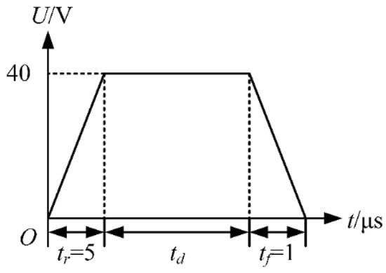
Figure 10.
Trapezoidal waveform.
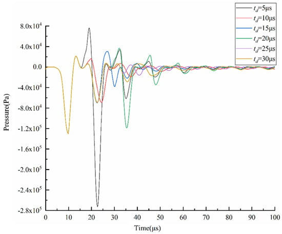
Figure 11.
Effect of td on the pressure at the nozzle.
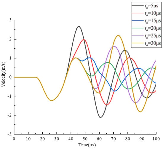
Figure 12.
Effect of td on the velocity at the nozzle.
The td is further optimized based on the simulation results of droplet generation at the nozzle, as shown in Figure 13. When the td is short, the droplets are generated with a long droplet tail due to excessive pressure variation. In this case, the printhead is likely to generate satellite droplets, which is not conducive to improving printing accuracy. When the td is long, the printhead cannot squeeze the ink out of the nozzle because the positive pressure is too small. It is also possible that the negative pressure is too small, so that the ligament cannot break up. this case, even if droplets can be generated, they are too small to be used for printing.
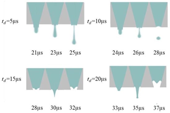
Figure 13.
Simulation results of droplet formation at the nozzle at different td.
As shown in Figure 13, when the td is 10 µs, droplets with optimal shape are generated. The optimal td value is initially determined as 10 µs to generate droplets with optimal shape. As the positive pressure increases, the ink is squeezed out of the chamber to form a ligament. Then, the positive pressure decreases, the negative pressure increases, and the ligament breaks up and forms a droplet with a round head and a slender tail. In order to verify the voltage applicability range of this parameter, the optimal actuating waveform at different driving voltages is simulated, and the results are shown in Figure 14. When the driving voltage is too small, the surface tension cannot be overcome, but the droplets show long trailing with satellite droplets with a large amplitude. The larger the amplitude of the voltage, the higher the speed of the liquid drop. Ultimately, when the voltage is greater than 30 V and less than 45 V, the jetting effect will not be unsatisfactory. The velocity contour of the optimal parameters is shown in Figure 15, which describes the velocity field change of the formation of the droplet. A significant increase in velocity is observed when droplets are formed.
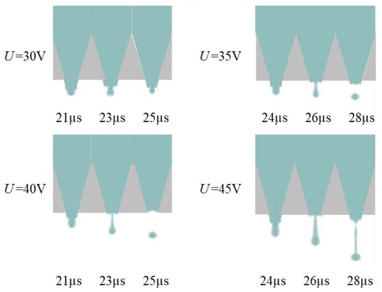
Figure 14.
Simulation results of droplet formation at the nozzle at different U.
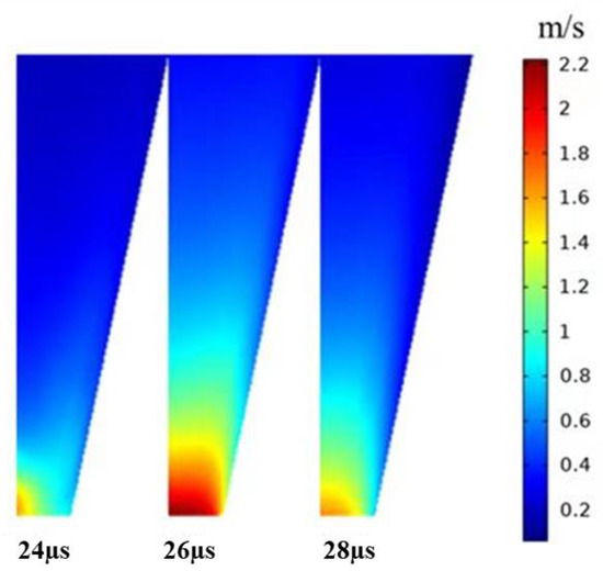
Figure 15.
The velocity contour of the optimal parameters.
In summary, the optimal parameters of the trapezoidal waveform initially determined by simulation analysis are tr = 5 µs, td = 10 µs, and tf = 1 µs, and this applies to voltage amplitude greater than 30 V and less than 45 V. In this study, the numerical model uses adaptive mesh refinement instead of overall fine dissection. The sparsity of the mesh dissection affects the correctness of the numerical simulation results. In practice, it is difficult to generate the ideal waveform for the simulation with the existing equipment. Therefore, the simulation results need to be verified experimentally, and the waveform parameters need to be further optimized accordingly.
4. Experimental Research
The experimental setup for observing the morphology of droplets is shown in Figure 16. The observation was achieved by a high-speed CCD camera with a microscope (Photron FASTCAM SA-5, Photron Corporation, Tokyo, Japan). The camera worked with a backlit light source to take pictures. A combination of an arbitrary waveform signal generator (AFG3022, Tektronix, Beaverton, OR, USA) and a voltage amplifier (PZD700, TREK, Waterloo, WI, USA) was used to actuate the piezoelectric printhead (MJ-AT, Microfab, Plano, TX, USA). The control program was written on LabVIEW (LabVIEW 2017, National Instruments, Austin, TX, USA) to programmatically control the arbitrary waveform signal generator and high-speed CCD camera via a PC. After the PC generates a trigger signal, several shutter signals are used to control the camera to take pictures of the droplet formation, thus recording the droplet shape.
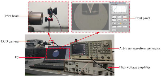
Figure 16.
Experimental setup.
To verify the numerical simulated optimized parameters of the trapezoidal waveform, two sets of experiments were carried out.
In the first set, the effect of different tr on the droplet morphology is observed. The td, tf, and U are set according to the optimized parameters determined by simulation (td = 10 µs, tf = 1 µs, U = 40 V), and the actuating frequency is set to 1 kHz. Meanwhile, the tr is set to 1 µs and 10 µs, respectively. The experimental results are shown in Figure 17.
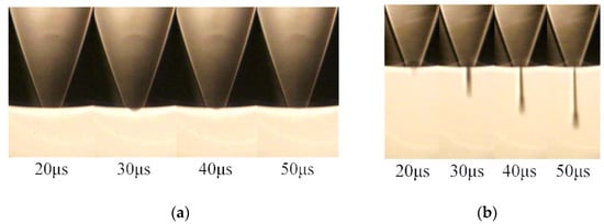
Figure 17.
Results of the first set: (a) the tr is 1 µs (b) the tr is 10 µs.
When the tr is 1 µs, fluctuation in the meniscus at the nozzle occurs during 20 to 50 µs. According to the analysis of the numerical simulation, when the tr is short, negative pressure at the nozzle is large, resulting in excessive ink being sucked into the nozzle. When the positive pressure wave reaches the nozzle, it causes fluctuations in the meniscus, so no droplet is generated. When the tr is 10 µs, droplets with a long droplet tail are generated at the nozzle. This is because when the tr is long, negative pressure at the nozzle is small, resulting in a small amount of ink being sucked into the nozzle. When the positive pressure wave reaches the nozzle, it is easy for the printhead to generate droplets, thus forming a long droplet tail, which is not good for controlling the shape and size of the droplets.
In the second set, the effect of different tf on droplet morphology is observed. The tr, td, and U are set according to the optimized parameters determined by simulation (tr = 5 µs, td = 10 µs, U = 40 V), and the actuating frequency is 1 kHz, setting tf to 1 µs and 5 µs, respectively. The experimental results are shown in Figure 18.
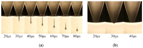
Figure 18.
Results of the second set: (a) the tf is 1 µs (b) the tf is 5 µs.
When the tf is 1 µs (the optimized parameters determined by simulation), the ink is squeezed out of the chamber to form a ligament. The ligament then breaks up and forms a droplet with a round head and a slender tail. According to the analysis of the numerical simulation, the appropriate pressure variation allows the printhead to generate droplets that are close to the ideal shape. When the tf is 5 µs, fluctuation in the meniscus at the nozzle occurs during 20 µs to 50 µs. This is because the positive pressure at the nozzle is too small to squeeze the ink out of the nozzle.
When the printhead is actuated by the optimized waveform with the tr = 5 µs, td = 10 µs, and tf = 1 µs, droplets with a slender droplet tail are generated at the nozzle. Therefore, further optimization of the parameters is required to generate droplets with optimal shape. According to the pressure wave propagation theory and the results of the numerical simulation, when the tf is 1 µs, the positive pressure at the nozzle is large, causing the printhead to squeeze out too much ink. This results in a droplet with a long droplet tail, which is not conducive to improving printing accuracy. Therefore, to reduce the positive pressure during ejection, the tf is set to 2 µs (other parameters are the same as in the second set) for the third set. The experimental result is shown in Figure 19, where the nozzle continuously ejects droplets with the optimal shape. The image processing and measurement program is written on LabVIEW using the Vision Development Module. The front panel of the program is shown in Figure 20. The diameter of this droplet is 29.2134 µm, which is about half the diameter of the nozzle. The droplet size is optimal, and the diameter and speed can be changed by varying the voltage amplitude.
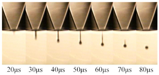
Figure 19.
Experimental results when the tf is 2 µs.
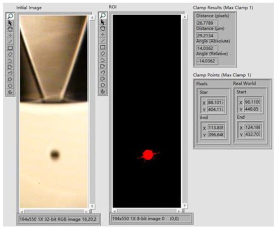
Figure 20.
The front panel of the image processing and measurement program.
In summary, when combining numerical simulations and experiments, the optimal waveform parameters are tr = 5 µs, td = 10 µs, tf = 2 µs, U = 40 V. The actuating frequency is 1 kHz. Figure 19 shows the sequential images of the droplet formation: (1) the piezoelectric part expands, creating a negative pressure in the chamber, and the printhead squeezes the ink out of the nozzle at 20 µs; (2) the ink is squeezed out of the chamber to form a ligament at 40 µs; (3) the ligament length increases with time during 40 to 50 µs; (4) the ligament breaks up at 60 µs; and (5) during 60 to 80 µs, the squeezed ink forms a droplet due to surface tension.
5. Conclusions
The proper actuating waveform can considerably improve the ejection performance of a piezoelectric printhead. This paper proposes a waveform design method for squeeze-type piezoelectric printheads based on a numerical simulation and experiment for the printing accuracy improvement of ejecting nano-silver conductive ink. A coupled multi-physics field piezoelectric printhead ejection model is developed using the commercial finite element analysis software COMSOL to initially optimize the parameters from the point of view of the effect on the pressure at the nozzle. To prevent excessive ink suck-back and satellite droplets, the optimal tr is initially determined to be 5 µs. To produce a large positive pressure at the time of the ejection, the optimal tf is initially determined to be 2 µs. The generation of droplets requires an appropriate pressure variation at the nozzle, so the optimal td is initially determined to be 10 µs. After that, experiments are conducted with other parameters fixed, and only tr and tf are changed. The experimental phenomena verify the simulation results, and the parameters are optimized further based on the experiments. Considering both the numerical simulations and experimental results, the optimal parameters of the actuating waveform are tr = 5 µs, td = 10 µs, tf = 2 µs, and U = 40 V. The results show that the squeeze-type piezoelectric printhead can eject continuously when actuated by the designed waveform. The droplets are in optimal shape, and the size is about half the diameter of the nozzle. Meanwhile, the method also demonstrates the feasibility of analyzing the droplet formation from the perspective of pressure variation at the nozzle.
Author Contributions
Conceptualization, X.S. and N.L.; methodology, N.L.; software, M.Z.; validation, N.L., M.Z. and W.H.; formal analysis, N.L.; investigation, M.Z.; resources, K.W.; data curation, N.L.; writing—original draft preparation, M.Z.; writing—review and editing, W.H.; visualization, X.S.; supervision, X.S.; project administration, X.S.; funding acquisition, X.S. All authors have read and agreed to the published version of the manuscript.
Funding
This work is supported by the National Natural Science Foundation of China under Grant 52075069 and 52005079 and by the Fundamental Research Funds for the Central Universities under Grant DUT21RC(3)069.
Conflicts of Interest
The authors declare no conflict of interest.
References
- Tekin, E.; Smith, P.J.; Schubert, U.S. Inkjet printing as a deposition and patterning tool for polymers and inorganic particles. Soft Matter 2008, 4, 703–713. [Google Scholar] [CrossRef] [PubMed]
- Liou, T.M.; Chan, C.Y.; Shih, K.C. Effects of actuating waveform, ink property, and nozzle size on piezoelectrically driven inkjet droplets. Microfluid. Nanofluidics 2010, 8, 575–586. [Google Scholar] [CrossRef]
- Salaoru, I.; Maswoud, S.; Paul, S. Inkjet printing of functional electronic memory cells: A step forward to green electronics. Micromachines 2019, 10, 417. [Google Scholar] [CrossRef]
- Li, Z.; Huang, J.; Yang, Y.; Yang, S.; Zhang, J.; Yuan, P.; Zhang, J. Additive manufacturing of conformal microstrip antenna using piezoelectric nozzle array. Appl. Sci. 2020, 10, 3082. [Google Scholar] [CrossRef]
- Kawase, T.; Shimoda, T.; Newsome, C.; Sirringhaus, H.; Friend, R.H. Inkjet printing of polymer thin film transistors. Thin Solid Films 2003, 438, 279–287. [Google Scholar] [CrossRef]
- Kwon, J.; Takeda, Y.; Shiwaku, R.; Tokito, S.; Cho, K.; Jung, S. Three-dimensional monolithic integration in flexible printed organic transistors. Nat. Commun. 2019, 10, 54. [Google Scholar] [CrossRef]
- Setti, L.; Fraleoni-Morgera, A.; Ballarin, B.; Filippini, A.; Frascaro, D.; Piana, C. An amperometric glucose biosensor prototype fabricated by thermal inkjet printing. Biosens. Bioelectron. 2005, 20, 2019–2026. [Google Scholar] [CrossRef] [PubMed]
- Kwon, K.S. Experimental analysis of waveform effects on satellite and ligament behavior via in situ measurement of the drop-on-demand drop formation curve and the instantaneous jetting speed curve. J. Micromechanics Microengineering 2010, 20, 115005. [Google Scholar] [CrossRef]
- Dijksman, J.F. Design of Piezo Inkjet Print Heads: From Acoustics to Applications; John Wiley & Sons: Hoboken, NJ, USA, 2018; pp. 193–196. [Google Scholar]
- Chang, J.; Jiang, F.; Shen, T.; Chi, M.; Huang, B. Waveform adjustment for obtaining higher quality droplets based on a multi-satellite droplet monitoring system. Mod. Phys. Lett. B 2019, 33, 1950105. [Google Scholar] [CrossRef]
- Kwon, K.S. Waveform design methods for piezo inkjet dispensers based on measured meniscus motion. J. Microelectromech. Syst. 2009, 18, 1118–1125. [Google Scholar] [CrossRef]
- Wu, H.C.; Shan, T.R.; Hwang, W.S.; Lin, H.J. Study of micro-droplet behavior for a piezoelectric inkjet printing device using a single pulse voltage pattern. Mater. Trans. 2014, 45, 1794–1801. [Google Scholar] [CrossRef]
- Liu, Y.F.; Pai, Y.F.; Tsai, M.H.; Hwang, W.S. Investigation of driving waveform and resonance pressure in piezoelectric inkjet printing. Appl. Phys. A 2012, 109, 323–329. [Google Scholar] [CrossRef]
- Xiao, X.; Wang, X.; Chen, D.; Dou, J.; Wang, S.; Zou, H. A waveform design method for piezoelectric inkjet printhead with doppler vibration test and numerical simulation. Microelectron. Eng. 2018, 196, 13–19. [Google Scholar] [CrossRef]
- Eshkalak, S.K.; Chinnappan, A.; Jayathilaka, W.A.D.M.; Khatibzadeh, M.; Kowsari, E.; Ramakrishna, S. A review on inkjet printing of cnt composites for smart applications. Appl. Mater. Today 2017, 9, 372–386. [Google Scholar] [CrossRef]
- Kwon, K.S.; Rahman, M.K.; Phung, T.H.; Hoath, S.D.; Jeong, S.; Kim, J.S. Review of digital printing technologies for electronic materials. Flex. Print. Electron. 2020, 5, 043003. [Google Scholar] [CrossRef]
- Shin, D.Y.; Grassia, P.; Derby, B. Oscillatory incompressible fluid flow in a tapered tube with a free surface in an inkjet print head. J. Fluids Eng. 2005, 127, 98–109. [Google Scholar] [CrossRef]
Publisher’s Note: MDPI stays neutral with regard to jurisdictional claims in published maps and institutional affiliations. |
© 2022 by the authors. Licensee MDPI, Basel, Switzerland. This article is an open access article distributed under the terms and conditions of the Creative Commons Attribution (CC BY) license (https://creativecommons.org/licenses/by/4.0/).