
Design and Development of an Upper Limb Rehabilitative Robot with Dual Functionality

 ,
, 
 ,
,  ,
, 

Abstract
1. Introduction
- (1)
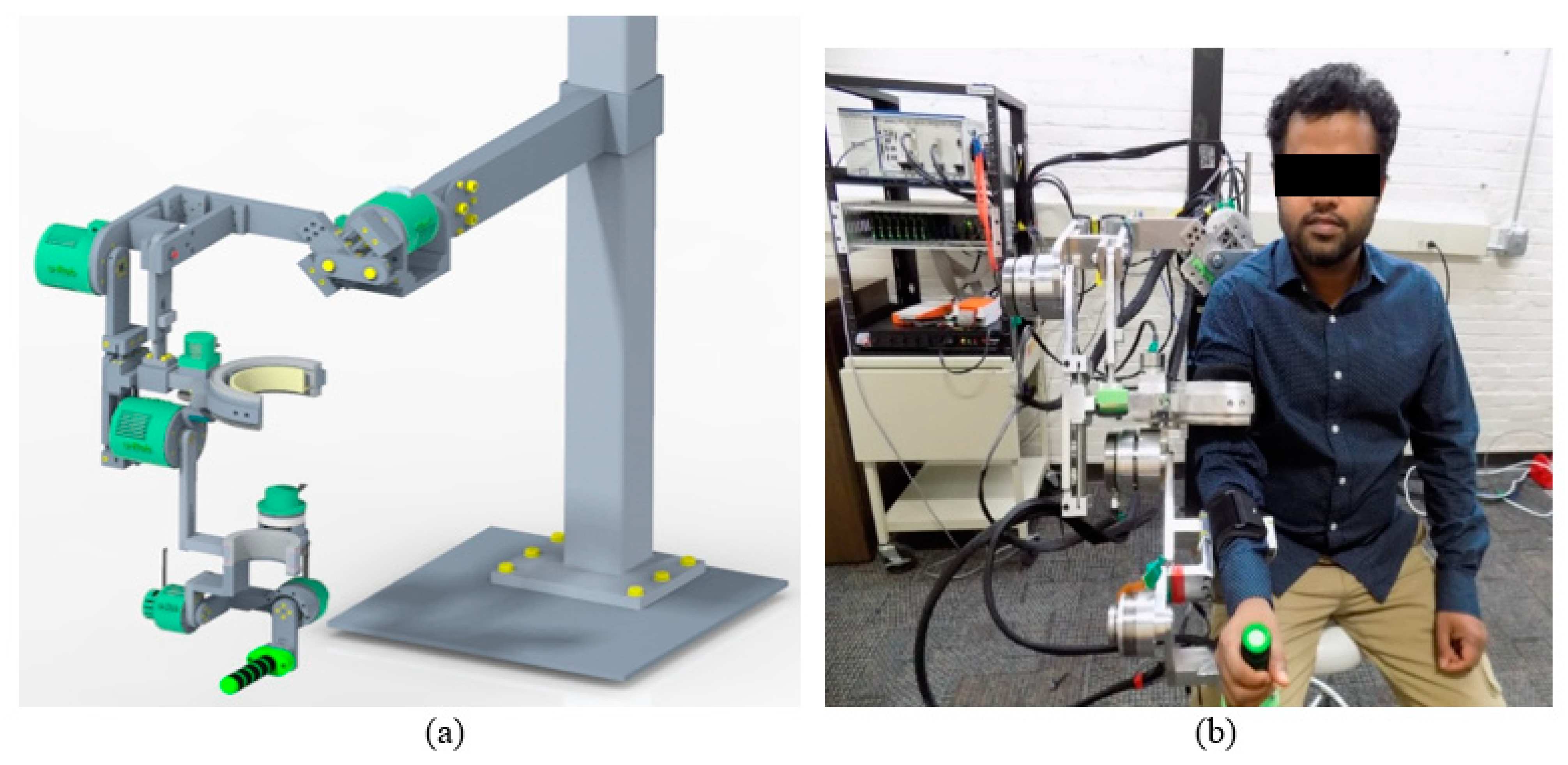
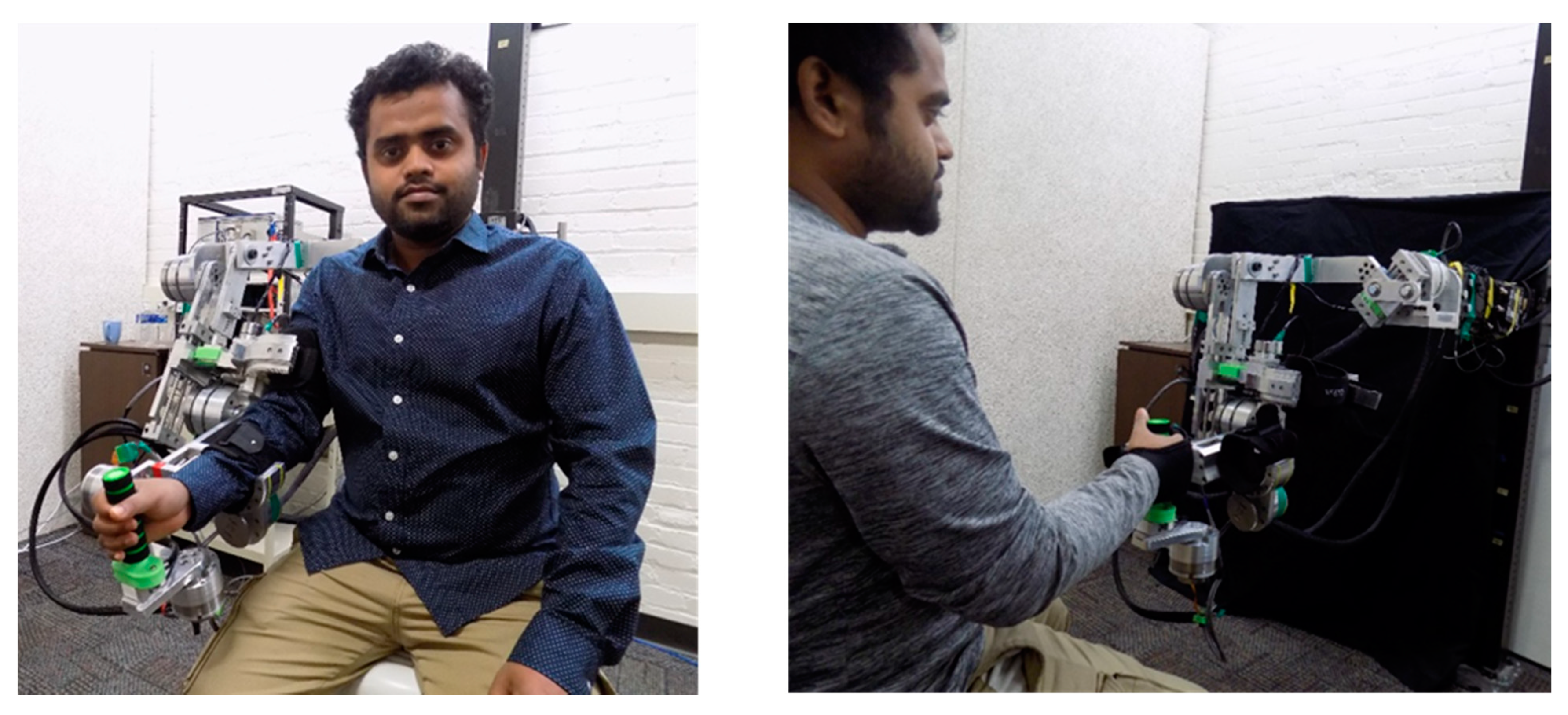
- A novel seven-DoF upper limb exoskeleton robot called ‘u-Rob’ was developed that functions as both an exoskeleton-type robot and an end-effector-type robot to perform joint-based and end-point exercises, respectively.
- (2)
- A sensorized upper arm cuff was designed and incorporated into u-Rob to measure and monitor the interaction forces at the upper arm.
2. Development of u-Rob
2.1. General Design Requirement
2.2. Development Procedure
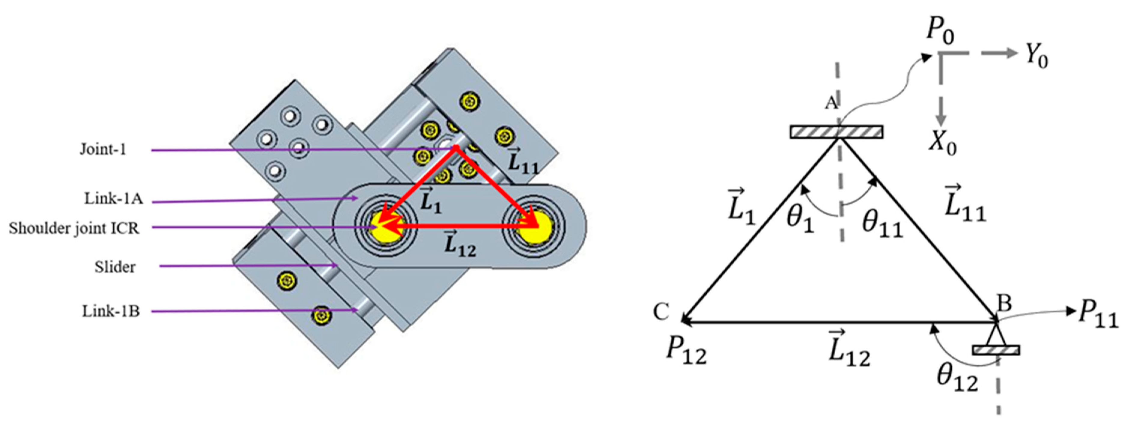
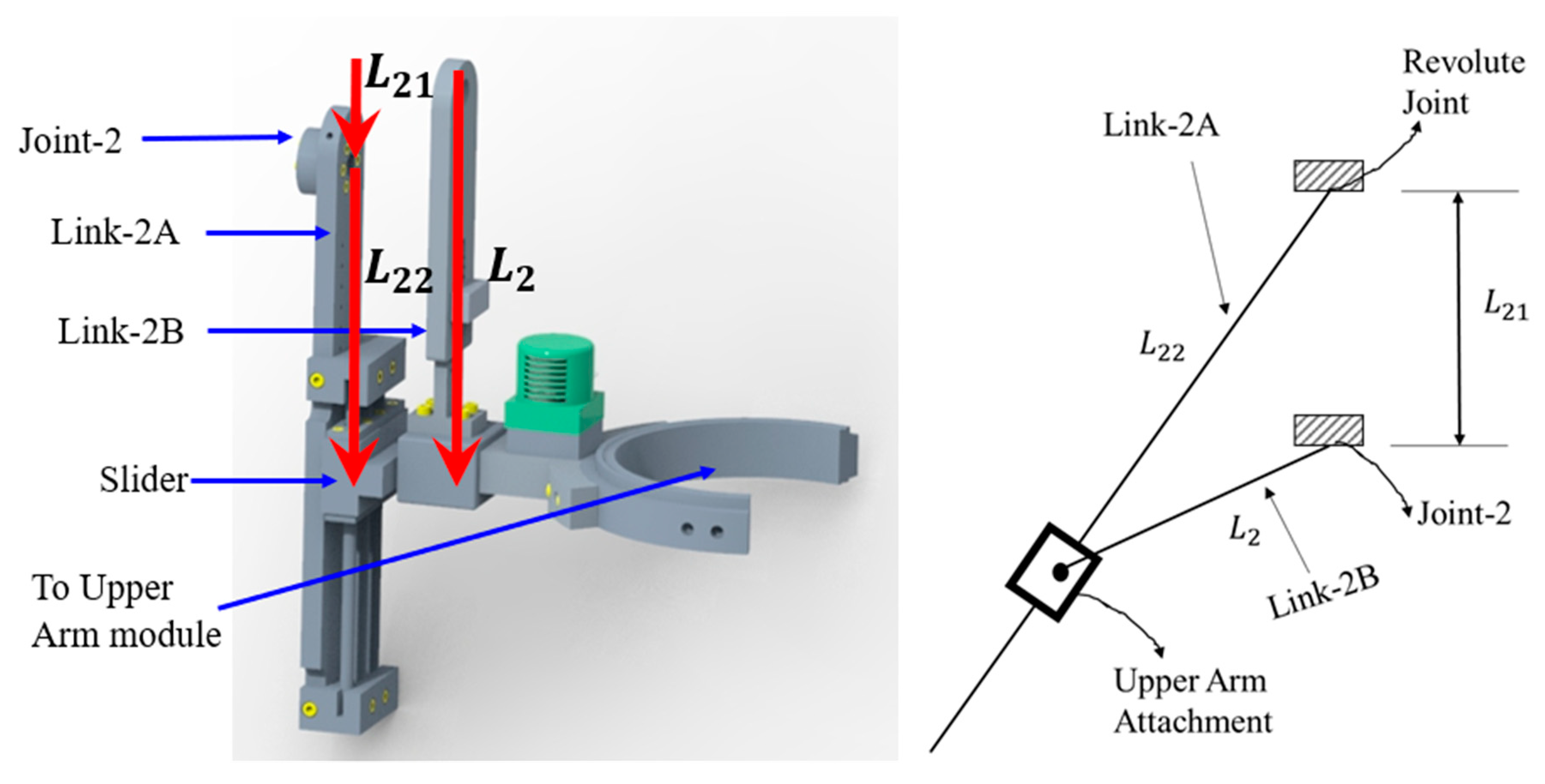
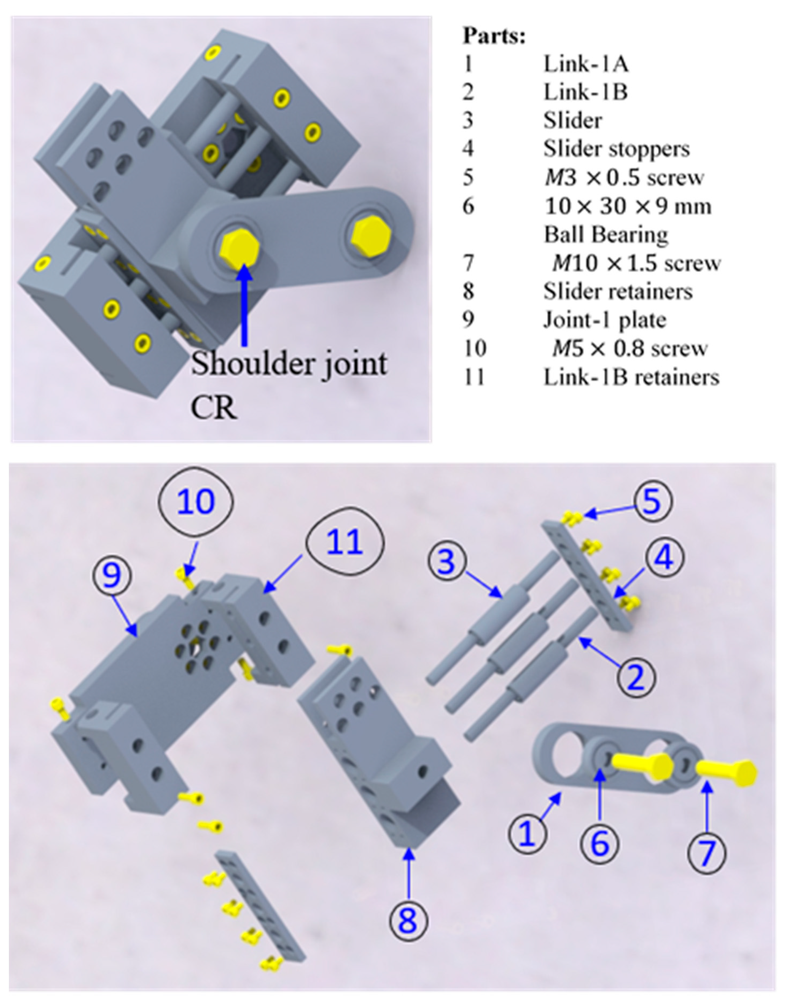
2.3. Shoulder Module
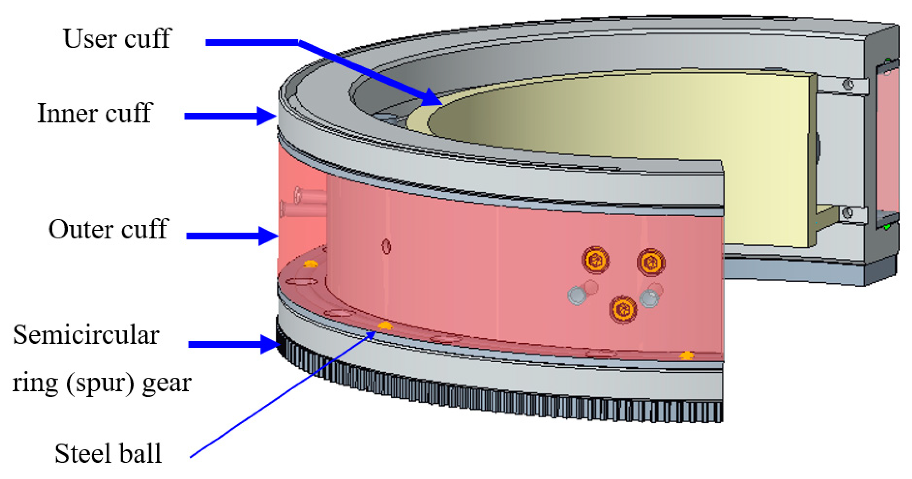
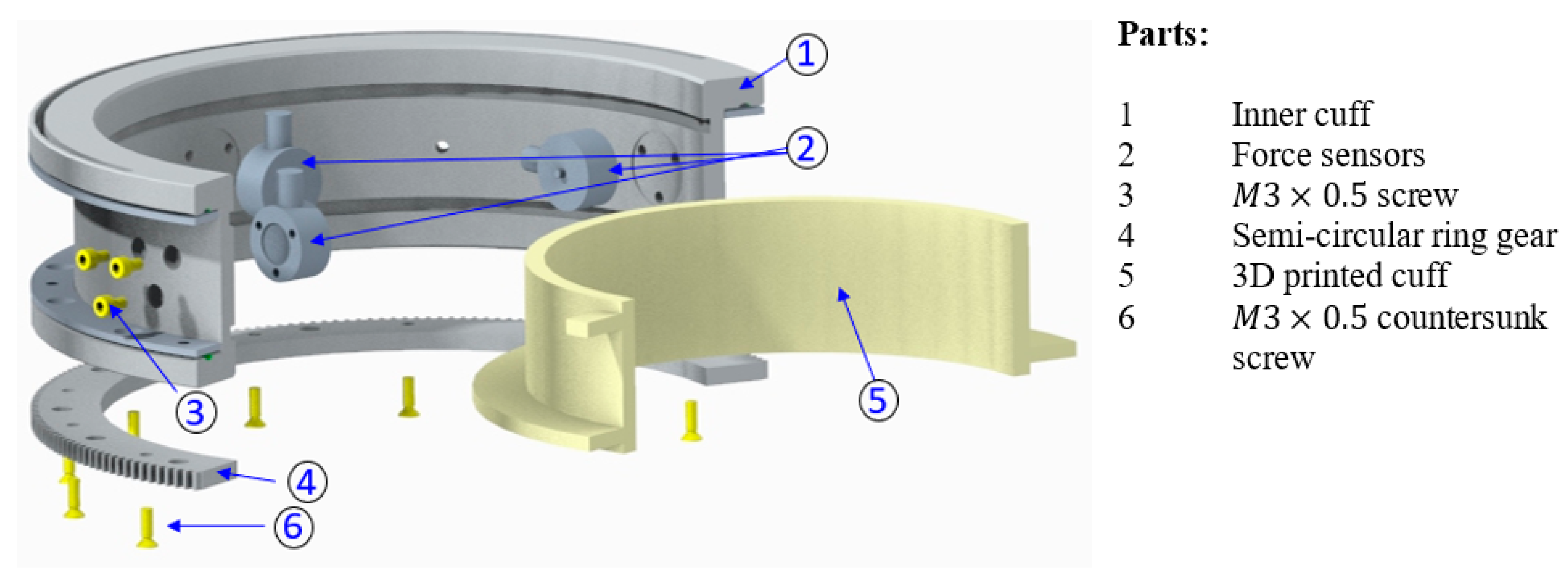
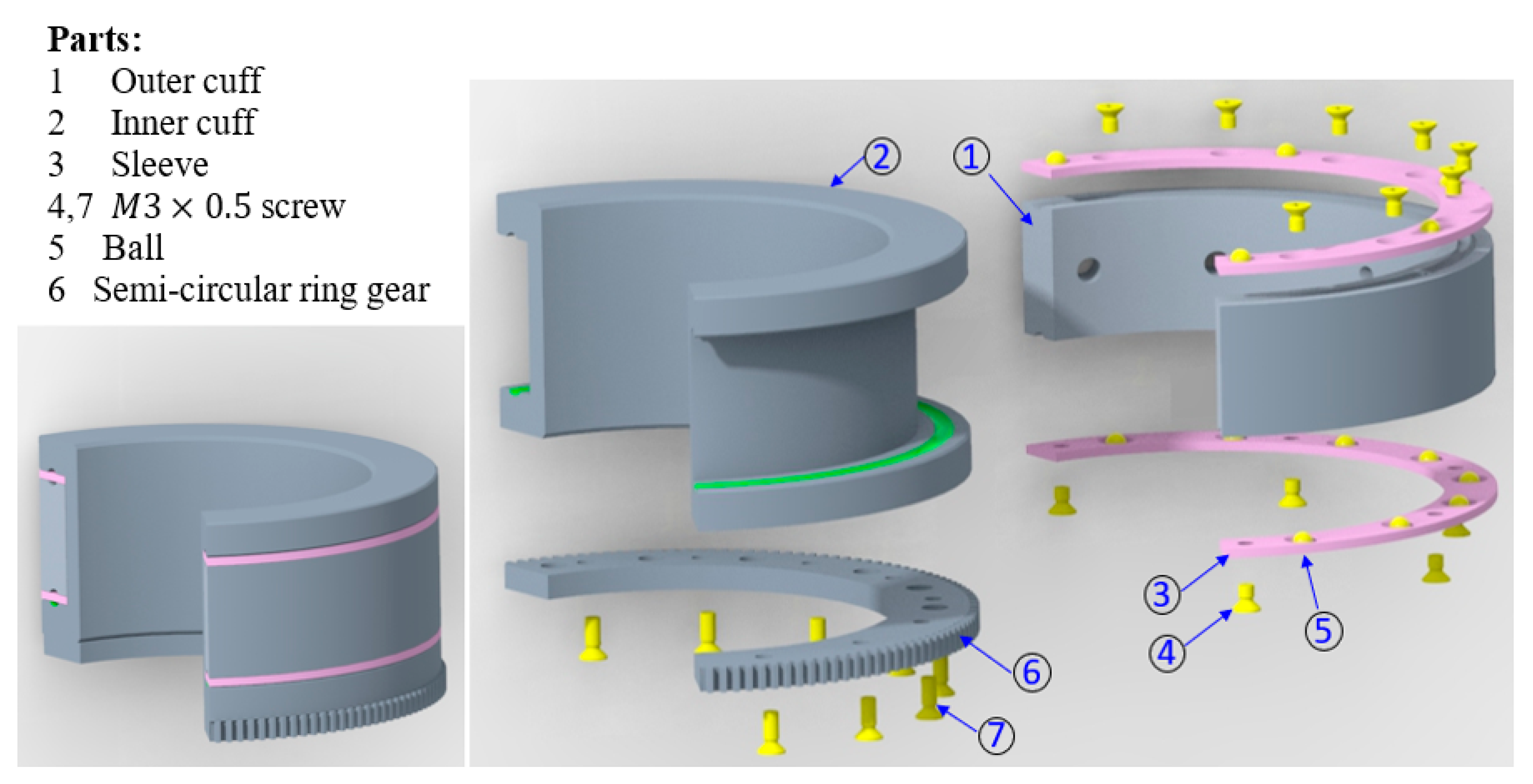
2.4. A New Sensorized Upper Arm Cuff
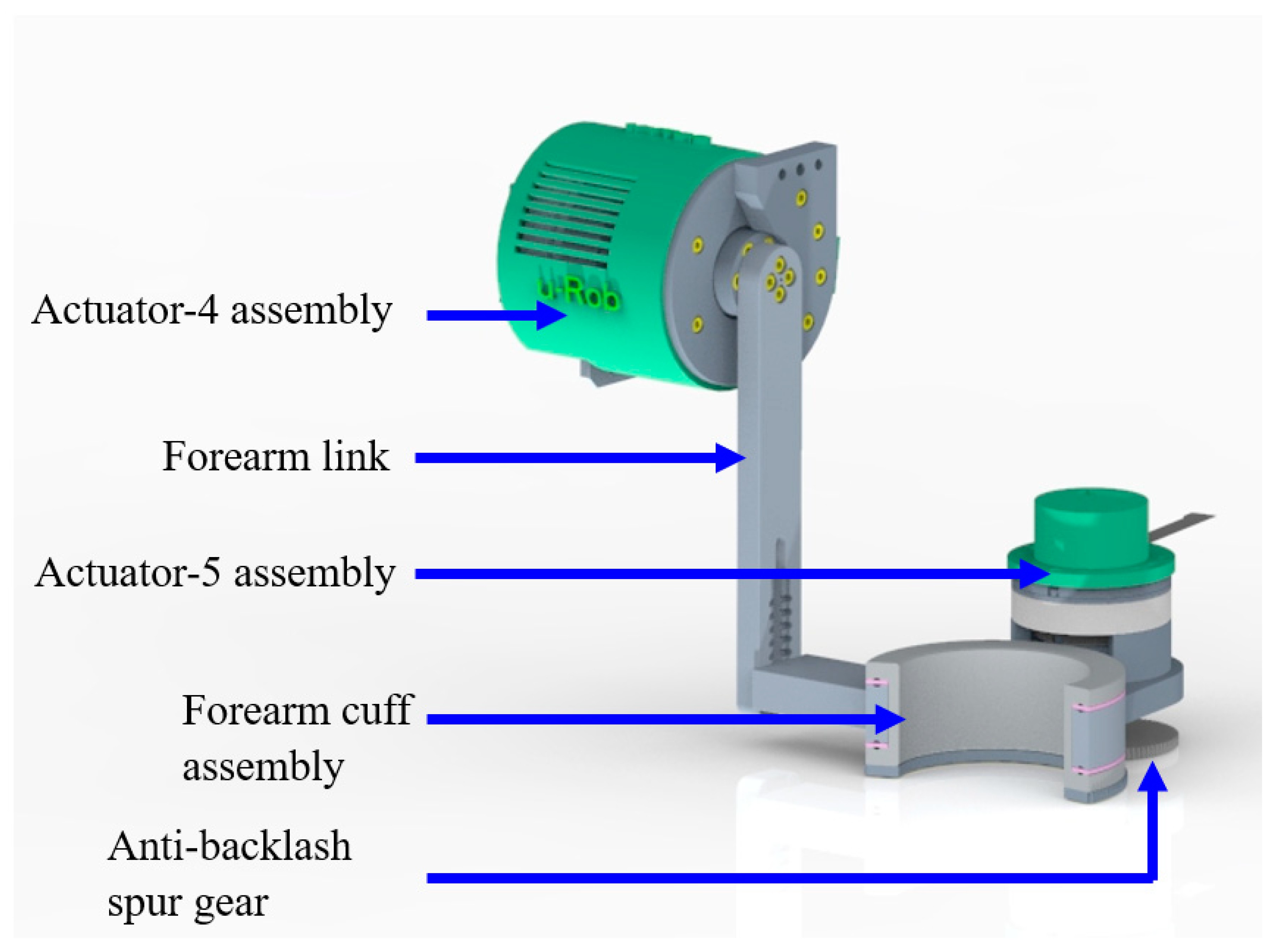
2.5. Elbow Module
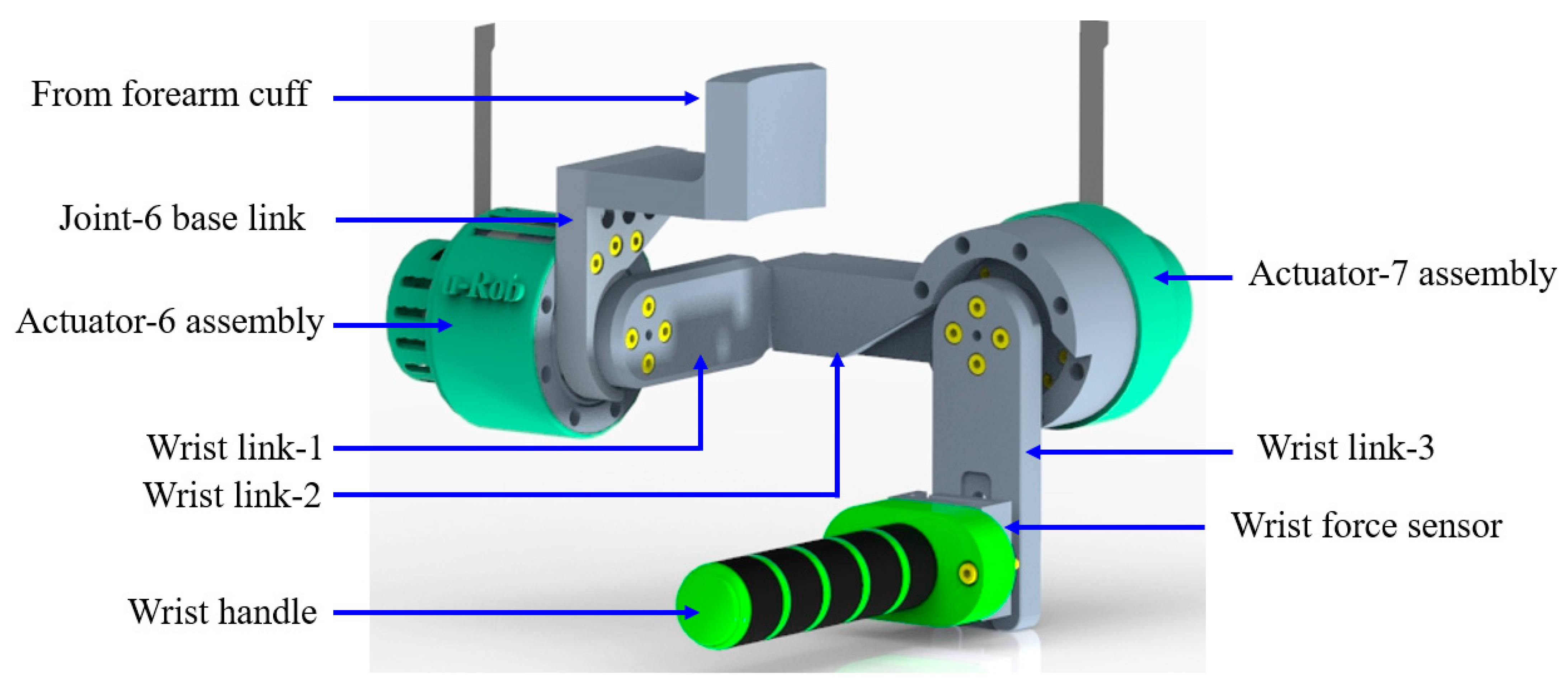
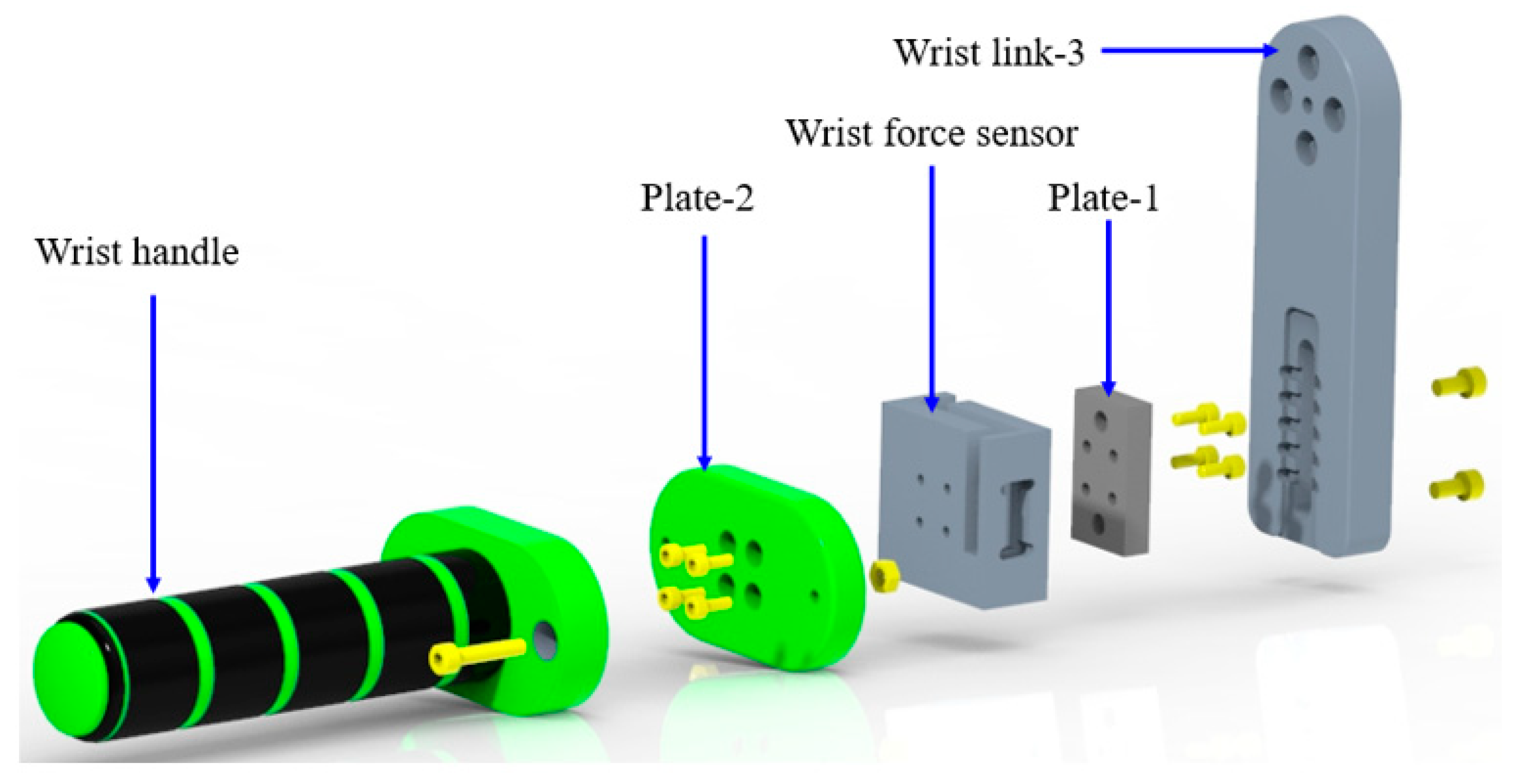
2.6. Wrist Module
2.7. Actuators and Reducers
2.8. Mass and Inertia Properties of the Proposed Exoskeleton Robot
2.9. Safety
3. Kinematics, Jacobian, and Dynamics
3.1. Kinematics
3.1.1. Kinematics of the Frontal Mechanism
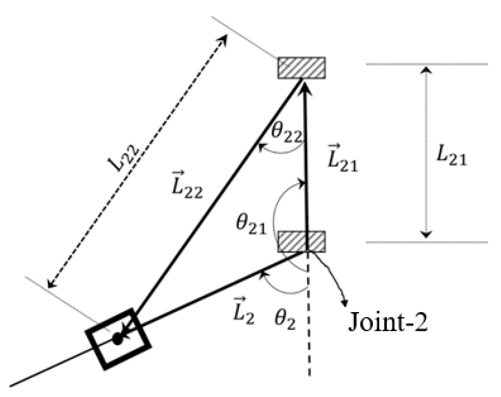
3.1.2. Kinematics of the Sagittal Mechanism
3.1.3. Kinematics of the Whole Robot
3.1.4. Jacobian
3.2. Dynamics
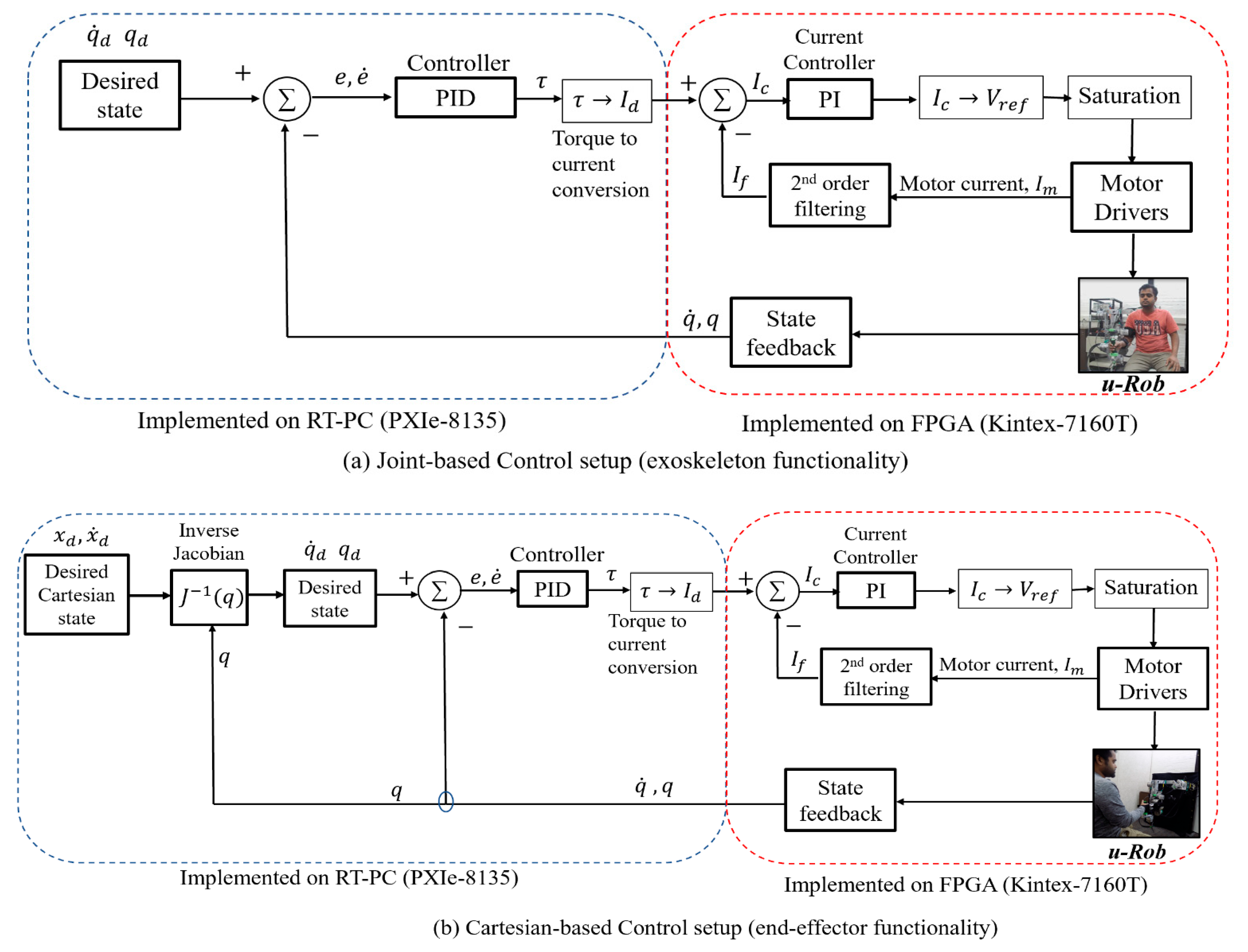
4. Control
5. Experiments and Results
5.1. Experimental Results for Joint-Based Exercises (Exoskeleton-Type Setup)
5.1.1. Shoulder Abduction–Adduction Exercise
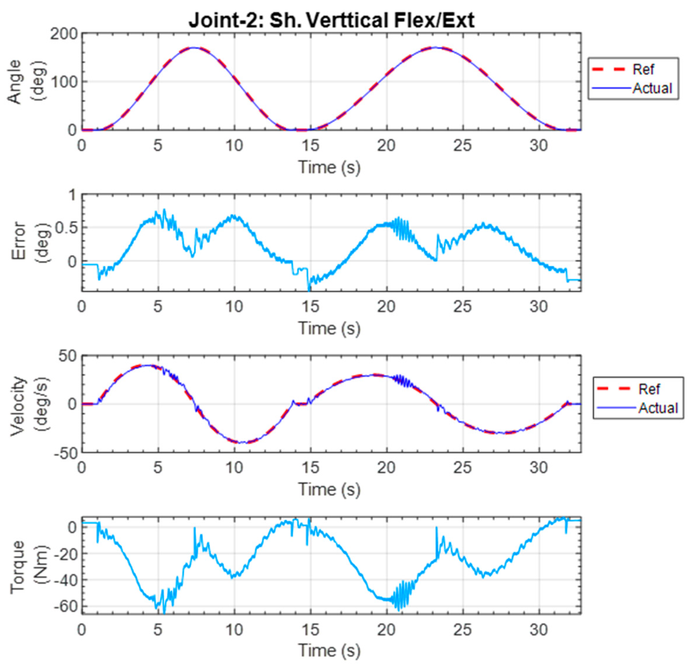
5.1.2. Shoulder Vertical Flexion–Extension Exercise
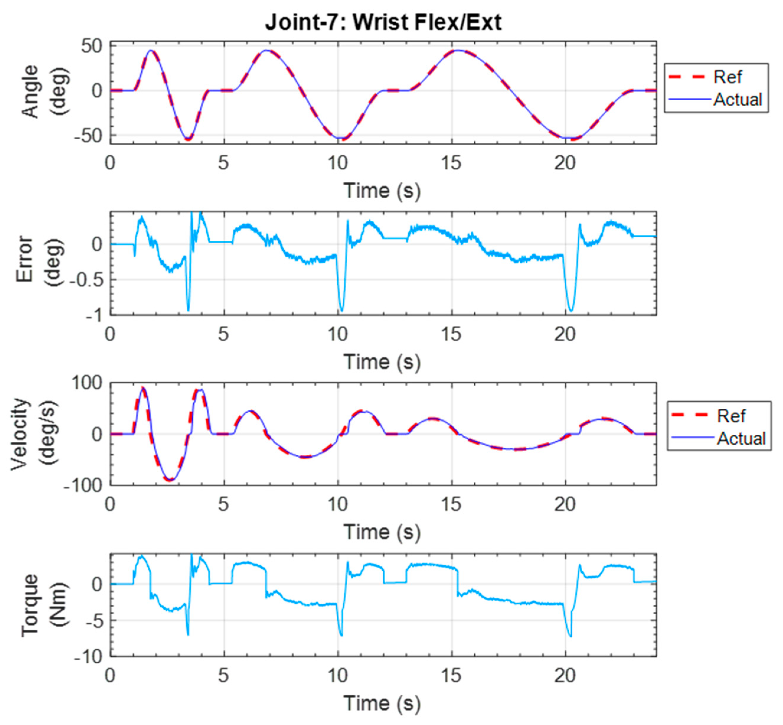
5.1.3. Wrist Flexion–Extension Exercise
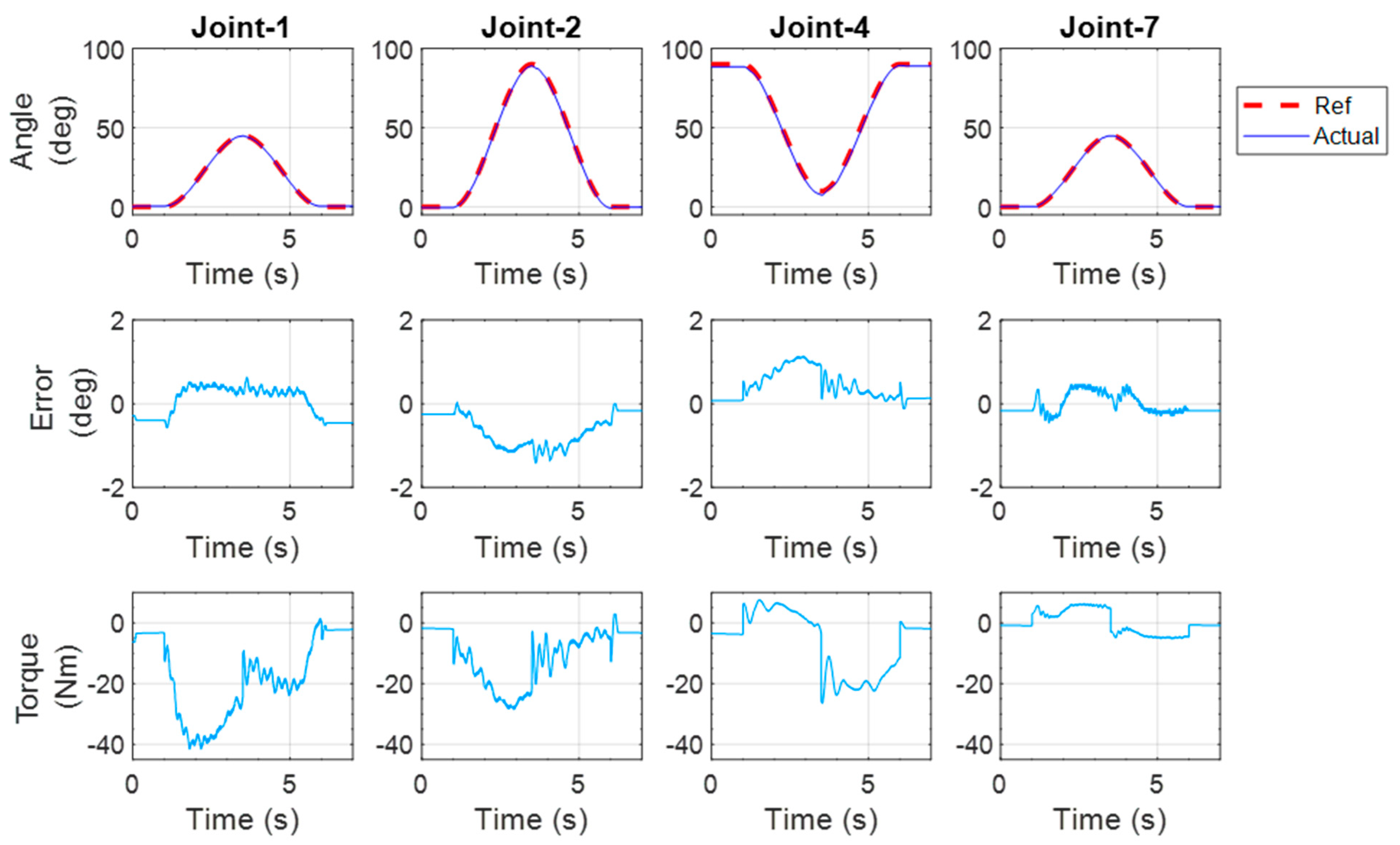
5.1.4. Simultaneous Joint Movement of the Shoulder, Elbow, and Wrist
5.1.5. Diagonal Reaching Exercise
5.2. Experimental Results for End-Point Exercises (End-Effector-Type Setup)
5.2.1. Reaching Exercise in the Transverse Plane
5.2.2. Forward Reaching in the Sagittal Plane
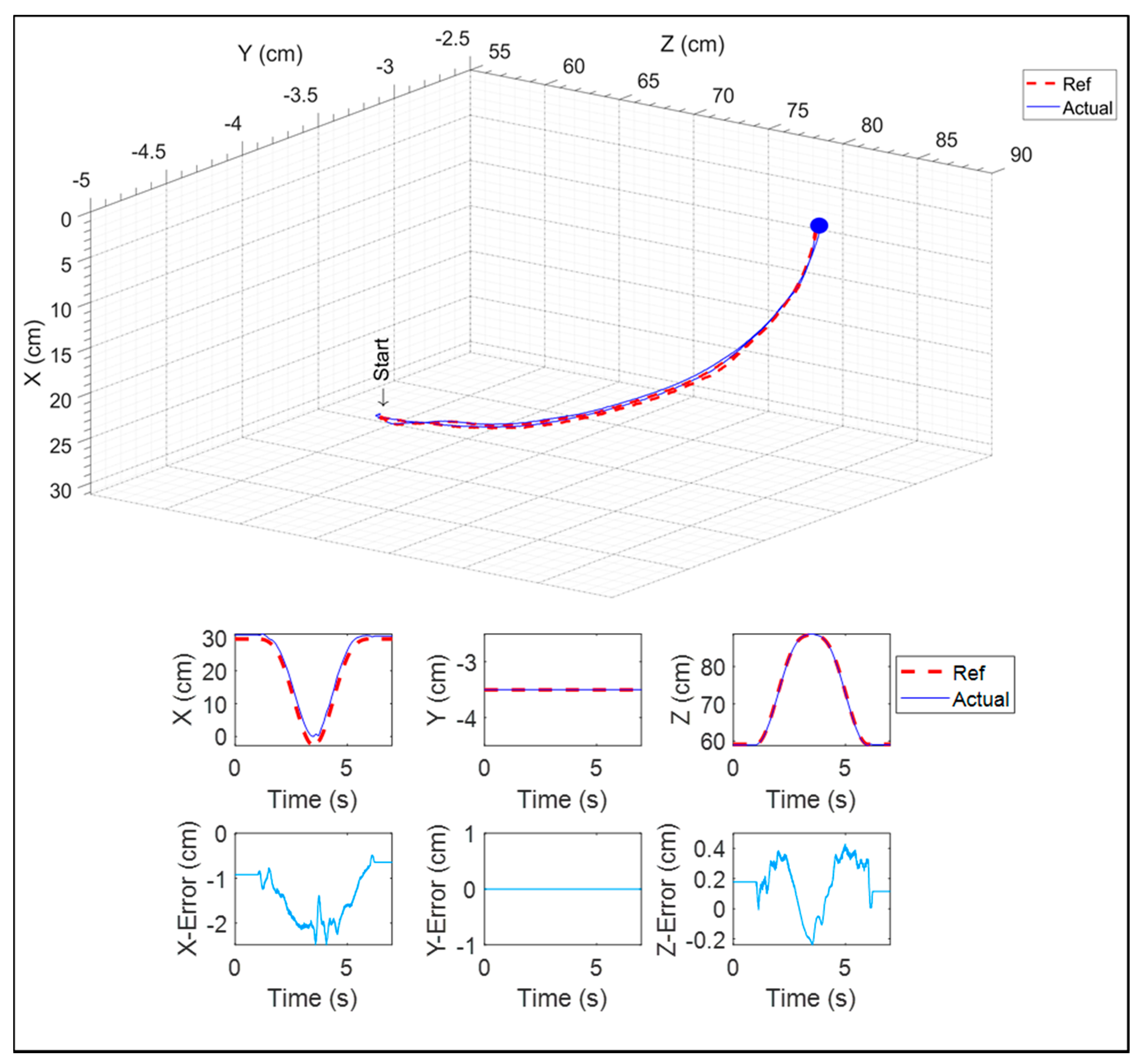
5.2.3. A 3D Reaching Exercise
6. Conclusions
Author Contributions
Funding
Institutional Review Board Statement
Conflicts of Interest
References
- Benjamin, E.J.; Muntner, P.; Alonso, A.; Bittencourt, M.S.; Callaway, C.W.; Carson, A.; Chamberlain, A.M.; Chang, A.R.; Cheng, S.; Das, S.R.; et al. Heart Disease and Stroke Statistics—2019 Update: A Report from the American Heart Association. Circulation 2019, 139, e56–e528. [Google Scholar] [CrossRef] [PubMed]
- Teasell, R.W.; Kalra, L. What’s New in Stroke Rehabilitation. Stroke 2004, 35, 383–385. [Google Scholar] [CrossRef] [PubMed]
- Lum, P.S.; Burgar, C.G.; Shor, P.C.; Majmundar, M.; Van der Loos, H.M. Robot-assisted movement training compared with conventional therapy techniques for the rehabilitation of upper-limb motor function after stroke. Arch. Phys. Med. Rehabil. 2002, 83, 952–959. [Google Scholar] [CrossRef]
- Badesa, F.J.; Morales, R.; Garcia-Aracil, N.; Sabater, J.; Casals, A.; Zollo, L. Auto-adaptive robot-aided therapy using machine learning techniques. Comput. Methods Programs Biomed. 2014, 116, 123–130. [Google Scholar] [CrossRef]
- Balasubramanian, S.; He, J. Adaptive Control of a Wearable Exoskeleton for Upper-Extremity Neurorehabilitation. Appl. Bionics Biomech. 2012, 9, 99–115. [Google Scholar] [CrossRef]
- Brahmi, B.; Saad, M.; Brahmi, A.; Luna, C.O.; Rahman, M.H. Compliant control for wearable exoskeleton robot based on human inverse kinematics. Int. J. Adv. Robot. Syst. 2018, 15. [Google Scholar] [CrossRef]
- Campolo, D.; Tommasino, P.; Gamage, K.; Klein, J.; Hughes, C.M.; Masia, L. H-Man: A planar, H-shape cabled differential robotic manipulandum for experiments on human motor control. J. Neurosci. Methods 2014, 235, 285–297. [Google Scholar] [CrossRef]
- Chen, Y.; Li, G.; Zhu, Y.; Zhao, J.; Cai, H. Design of a 6-DOF upper limb rehabilitation exoskeleton with parallel actuated joints. Bio-Med. Mater. Eng. 2014, 24, 2527–2535. [Google Scholar] [CrossRef]
- Christensen, S.; Bai, S. A Novel Shoulder Mechanism with a Double Parallelogram Linkage for Upper-Body Exoskeletons; Springer International Publishing: Cham, Switzerland, 2017; pp. 51–56. [Google Scholar]
- Fraile, J.C.; Turiel, J.P.; Baeyens, E.; Viñas, P.; Alonso, R.; Cuadrado, A.; Franco-Martin, M.; Parra, E.; Ayuso, L.; García-Bravo, F.; et al. E2Rebot: A robotic platform for upper limb rehabilitation in patients with neuromotor disability. Adv. Mech. Eng. 2016, 8. [Google Scholar] [CrossRef]
- Garrido, J.; Yu, W.; Li, X. Modular design and control of an upper limb exoskeleton. J. Mech. Sci. Technol. 2016, 30, 2265–2271. [Google Scholar] [CrossRef]
- Kiguchi, K.; Hayashi, Y. An EMG-Based Control for an Upper-Limb Power-Assist Exoskeleton Robot. IEEE Trans. Syst. Man, Cybern. Part B 2012, 42, 1064–1071. [Google Scholar] [CrossRef]
- Kim, B.; Deshpande, A.D. Controls for the shoulder mechanism of an upper-body exoskeleton for promoting scapulohumeral rhythm. In Proceedings of the 2015 IEEE International Conference on Rehabilitation Robotics (ICORR), Singapore, 11–14 August 2015; pp. 538–542. [Google Scholar]
- Nef, T.; Guidali, M.; Riener, R. ARMin III—Arm Therapy Exoskeleton with an Ergonomic Shoulder Actuation. Appl. Bionics Biomech. 2009, 6, 962956. [Google Scholar] [CrossRef]
- Nef, T.; Mihelj, M.; Kiefer, G.; Perndl, C.; Muller, R.; Riener, R. ARMin—Exoskeleton for Arm Therapy in Stroke Patients. In Proceedings of the 2007 IEEE 10th International Conference on Rehabilitation Robotics, Noordwijk, The Netherlands, 13–15 June 2007; pp. 68–74. [Google Scholar]
- Otten, A.; Voort, C.; Stienen, A.; Aarts, R.; van Asseldonk, E.; van der Kooij, H. LIMPACT:A Hydraulically Powered Self-Aligning Upper Limb Exoskeleton. IEEE/ASME Trans. Mechatron. 2015, 20, 2285–2298. [Google Scholar] [CrossRef]
- Rahman, M.H.; Cristobal, O.L.; Saad, M.; Kenné, J.-P.; Archambault, P.S. Development of a whole arm wearable robotic exoskeleton for rehabilitation and to assist upper limb movements. Robotica 2014, 33, 19–39. [Google Scholar] [CrossRef]
- Zhang, L.; Guo, S.; Sun, Q. Development and Assist-As-Needed Control of an End-Effector Upper Limb Rehabilitation Robot. Appl. Sci. 2020, 10, 6684. [Google Scholar] [CrossRef]
- Brahim, B.; Ochoa-Luna, C.; Saad, M.; Zaman, A.U.; Islam, R.; Rahman, M.H. A new adaptive super-twisting control for an exoskeleton robot with dynamic uncertainties. In Proceedings of the 2017 IEEE Great Lakes Biomedical Conference (GLBC), Milwaukee, WI, USA, 6–7 April 2017. [Google Scholar]
- Cui, X.; Chen, W.; Jin, X.; Agrawal, S.K. Design of a 7-DOF Cable-Driven Arm Exoskeleton (CAREX-7) and a Controller for Dexterous Motion Training or Assistance. IEEE/ASME Trans. Mechatron. 2016, 22, 161–172. [Google Scholar] [CrossRef]
- Fellag, R.; Benyahia, T.; Drias, M.; Guiatni, M.; Hamerlain, M. Sliding mode control of a 5 dofs upper limb exoskeleton robot. In Proceedings of the 2017 5th International Conference on Electrical Engineering—Boumerdes (ICEE-B), Boumerdes, Algeria, 29–31 October 2017; pp. 1–6. [Google Scholar]
- Xiao, F.; Gao, Y.; Wang, Y.; Zhu, Y.; Zhao, J. Design and evaluation of a 7-DOF cable-driven upper limb exoskeleton. J. Mech. Sci. Technol. 2018, 32, 855–864. [Google Scholar] [CrossRef]
- Bouteraa, Y.; Ben Abdallah, I.; Elmogy, A.M. Training of Hand Rehabilitation Using Low Cost Exoskeleton and Vision-Based Game Interface. J. Intell. Robot. Syst. 2019, 96, 31–47. [Google Scholar] [CrossRef]
- Krebs, H.I.; Volpe, B.T.; Williams, D.; Celestino, J.; Charles, S.K.; Lynch, D.; Hogan, N. Robot-Aided Neurorehabilitation: A Robot for Wrist Rehabilitation. IEEE Trans. Neural Syst. Rehabil. Eng. 2007, 15, 327–335. [Google Scholar] [CrossRef]
- Lee, S.H.; Park, G.; Cho, D.Y.; Kim, H.Y.; Lee, J.-Y.; Kim, S.; Park, S.-B.; Shin, J.-H. Comparisons between end-effector and exoskeleton rehabilitation robots regarding upper extremity function among chronic stroke patients with moderate-to-severe upper limb impairment. Sci. Rep. 2020, 10, 1806–1808. [Google Scholar] [CrossRef]
- Hefter, H.; Jost, W.H.; Reissig, A.; Zakine, B.; Bakheit, A.M.; Wissel, J. Classification of posture in poststroke upper limb spasticity: A potential decision tool for botulinum toxin A treatment? Int. J. Rehabil. Res. 2012, 35, 227–233. [Google Scholar] [CrossRef]
- Islam, M.R.; Brahmi, B.; Ahmed, T.; Assad-Uz-Zaman, M.; Rahman, M.H. Chapter 9—Exoskeletons in upper limb rehabilitation: A review to find key challenges to improve functionality. In Control Theory in Biomedical Engineering; Boubaker, O., Ed.; Academic Press: Cambridge, MA, USA, 2020; pp. 235–265. [Google Scholar]
- Sadeque, M.; Balachandran, S.K. Chapter 10—Overview of medical device processing. In Trends in Development of Medical Devices; Shanmugam, P.S.T., Chokkalingam, L., Bakthavachalam, P., Boubaker, O., Eds.; Academic Press: Cambridge, MA, USA, 2020; pp. 177–188. [Google Scholar]
- Jiang, L.; Dou, Z.-L.; Wang, Q.; Wang, Q.-Y.; Dai, M.; Wang, Z.; Wei, X.-M.; Chen, Y.-B. Evaluation of clinical outcomes of patients with post-stroke wrist and finger spasticity after ultrasonography-guided BTX-A injection and rehabilitation training. Front. Hum. Neurosci. 2015, 9, 485. [Google Scholar] [CrossRef]
- Kwakkel, G.; Kollen, B.J.; Van Der Grond, J.; Prevo, A.J. Probability of Regaining Dexterity in the Flaccid Upper Limb. Stroke 2003, 34, 2181–2186. [Google Scholar] [CrossRef]
- Bai, S.; Christensen, S.; Islam, M.R.U. An upper-body exoskeleton with a novel shoulder mechanism for assistive applications. In Proceedings of the 2017 IEEE International Conference on Advanced Intelligent Mechatronics (AIM), Munich, Germany, 3–7 July 2017; pp. 1041–1046. [Google Scholar] [CrossRef]
- Sutapun, A.; Sangveraphunsiri, V. A 4-DOF Upper Limb Exoskeleton for Stroke Rehabilitation: Kinematics Mechanics and Control. Int. J. Mech. Eng. Robot. Res. 2015, 4, 269–272. [Google Scholar] [CrossRef]
- Liu, L.; Shi, Y.-Y.; Xie, L. A Novel Multi-Dof Exoskeleton Robot For Upper Limb Rehabilitation. J. Mech. Med. Biol. 2016, 16, 1640023. [Google Scholar] [CrossRef]
- Madani, T.; Daachi, B.; Djouani, K. Modular-Controller-Design-Based Fast Terminal Sliding Mode for Articulated Exoskeleton Systems. IEEE Trans. Control. Syst. Technol. 2016, 25, 1133–1140. [Google Scholar] [CrossRef]
- Mahdavian, M.; Toudeshki, A.G.; Yousefi-Koma, A. Design and fabrication of a 3DoF upper limb exoskeleton. In Proceedings of the 2015 3rd RSI International Conference on Robotics and Mechatronics (ICROM), Tehran, Iran, 7–9 October 2015; pp. 342–346. [Google Scholar]
- Perry, J.C.; Rosen, J.; Burns, S. Upper-Limb Powered Exoskeleton Design. IEEE/ASME Trans. Mechatron. 2007, 12, 408–417. [Google Scholar] [CrossRef]
- Stroppa, F.; Loconsole, C.; Marcheschi, S.; Frisoli, A. A Robot-Assisted Neuro-Rehabilitation System for Post-Stroke Patients’ Motor Skill Evaluation with ALEx Exoskeleton. In Converging Clinical and Engineering Research on Neurorehabilitation II; Springer International Publishing: Cham, Switzerland, 2017; pp. 501–505. [Google Scholar]
- Tang, Z.; Zhang, K.; Sun, S.; Gao, Z.; Zhang, L.; Yang, Z. An Upper-Limb Power-Assist Exoskeleton Using Proportional Myoelectric Control. Sensors 2014, 14, 6677–6694. [Google Scholar] [CrossRef] [PubMed]
- Gopura, R.; Bandara, D.; Kiguchi, K.; Mann, G. Developments in hardware systems of active upper-limb exoskeleton robots: A review. Robot. Auton. Syst. 2016, 75, 203–220. [Google Scholar] [CrossRef]
- Kiguchi, K.; Rahman, M.H.; Sasaki, M.; Teramoto, K. Development of a 3DOF mobile exoskeleton robot for human upper-limb motion assist. Robot. Auton. Syst. 2008, 56, 678–691. [Google Scholar] [CrossRef]
- Kim, B.; Deshpande, A.D. An upper-body rehabilitation exoskeleton Harmony with an anatomical shoulder mechanism: Design, modeling, control, and performance evaluation. Int. J. Robot. Res. 2017, 36, 414–435. [Google Scholar] [CrossRef]
- Hou, Y.; Kiguchi, K. Virtual Tunnel Generation Algorithm for Perception-Assist with an Upper-Limb Exoskeleton Robot. In Proceedings of the 2018 IEEE International Conference on Cyborg and Bionic Systems (CBS), Shenzhen, China, 25–27 October 2018; pp. 204–209. [Google Scholar] [CrossRef]
- Islam, M.; Spiewak, C.; Rahman, M.; Fareh, R. A Brief Review on Robotic Exoskeletons for Upper Extremity Rehabilitation to Find the Gap between Research Porotype and Commercial Type. Adv. Robot. Autom. 2017, 6, 2. [Google Scholar] [CrossRef]
- Jarrassé, N.; Proietti, T.; Crocher, V.; Robertson, J.; Sahbani, A.; Morel, G.; Roby-Brami, A. Robotic Exoskeletons: A Perspective for the Rehabilitation of Arm Coordination in Stroke Patients. Front. Hum. Neurosci. 2014, 8, 947. (In English) [Google Scholar] [CrossRef]
- Maciejasz, P.; Eschweiler, J.; Gerlach-Hahn, K.; Jansen-Troy, A.; Leonhardt, S. A survey on robotic devices for upper limb rehabilitation. J. NeuroEngineering Rehabil. 2014, 11, 3. [Google Scholar] [CrossRef] [PubMed]
- Gates, D.H.; Walters, L.S.; Cowley, J.C.; Wilken, J.; Resnik, L. Range of Motion Requirements for Upper-Limb Activities of Daily Living. Am. J. Occup. Ther. 2015, 70, 7001350010. [Google Scholar] [CrossRef] [PubMed]
- Hamilton, N.; Weimar, W.; Luttgens, K. Kinesiology: Scientific Basis of Human Motion, 12th ed.; McGraw-Hill: New York, NY, USA, 2012. [Google Scholar]
- Kim, K.; Park, D.S.; Ko, B.W.; Lee, J.; Yang, S.N.; Kim, J.; Song, W.K. Arm motion analysis of stroke patients in activities of daily living tasks: A preliminary study. In Proceedings of the 2011 Annual International Conference of the IEEE Engineering in Medicine and Biology Society, Boston, MA, USA, 30 August–3 September 2011; pp. 1287–1291. [Google Scholar]
- Namdari, S.; Yagnik, G.; Ebaugh, D.D.; Nagda, S.; Ramsey, M.L.; Williams, G.R.; Mehta, S. Defining functional shoulder range of motion for activities of daily living. J. Shoulder Elb. Surg. 2012, 21, 1177–1183. [Google Scholar] [CrossRef] [PubMed]
- Eckstrand, G.A.; Van Cott, H.P.; Kinkade, R.G. Human Engineering Guide to Equipment Design. Am. J. Psychol. 1973, 86, 891. [Google Scholar] [CrossRef]
- Halder, A.M.; Itoi, E.; An, K.N. Anatomy and biomechanics of the shoulder. Orthop. Clin. N. Am. 2000, 31, 159–176. [Google Scholar] [CrossRef]
- Winter, D.A. Anthropometry. In Biomechanics and Motor Control of Human Movement; John Wiley & Sons: New York, NY, USA, 2009; p. 370. [Google Scholar]
- De Caro, J.S.; Islam, R.; Montenegro, E.M.; Brahmi, B.; Rahman, M. Inverse Kinematic solution of u-Rob4 an hybrid exoskeleton for stroke rehabilitation. In Proceedings of the 2021 18th International Multi-Conference on Systems, Signals & Devices (SSD), Monastir, Tunisia, 22–25 March 2021; pp. 755–764. [Google Scholar] [CrossRef]
- Islam, R.; Zaman, A.U.; Swapnil, A.A.Z.; Ahmed, T.; Rahman, M.H. An ergonomic shoulder for robot-aided rehabilitation with hybrid control. Microsyst. Technol. 2020, 27, 159–172. [Google Scholar] [CrossRef]
- Islam, M.R.; Assad-Uz-Zaman, M.; Rahman, M.H. Design and control of an ergonomic robotic shoulder for wearable exoskeleton robot for rehabilitation. Int. J. Dyn. Control. 2020, 8, 312–325. [Google Scholar] [CrossRef]
- Islam, R.; Rahmani, M.; Rahman, M.H. A Novel Exoskeleton with Fractional Sliding Mode Control for Upper Limb Rehabilitation. Robotica 2020, 38, 2099–2120. [Google Scholar] [CrossRef]
- Denavit, J.; Hartenberg, R.S. A Kinematic Notation for Lower-Pair Mechanisms Based on Matrices. J. Appl. Mech. 1955, 22, 215–221. [Google Scholar] [CrossRef]
- Craig, J.J. Introduction to Robotics: Mechanics and Control, 4th ed.; Pearson: Upper Saddle River, NJ, USA, 2017; 448p. [Google Scholar]
- Lenar, J.; Klop, N. Positional kinematics of humanoid arms. Robotica 2006, 24, 105–112. [Google Scholar] [CrossRef]
- Lakhal, O.; Melingui, A.; Merzouki, R. Hybrid Approach for Modeling and Solving of Kinematics of a Compact Bionic Handling Assistant Manipulator. IEEE/ASME Trans. Mechatron. 2015, 21, 1326–1335. [Google Scholar] [CrossRef]
- Siciliano, B.; Sciavicco, L.; Villani, L.; Oriolo, G. Robotics (Modelling, Planning and Control); Springer: London, UK, 2009. [Google Scholar]
- FlintRehab. Arm Exercises for Stroke Patients. Available online: https://www.flintrehab.com/arm-exercises-for-stroke-patients (accessed on 12 January 2021).
- WebMD. Stroke Rehab to Regain Arm Movement. Available online: https://www.webmd.com/stroke/ss/slideshow-stroke (accessed on 12 January 2021).


| Limb Segment | Joint No. | Kind of Motion | ROM |
|---|---|---|---|
| Shoulder | Joint-1 | Abduction | 90° |
| Adduction | 0° | ||
| Joint-2 | Vertical flexion | 180° | |
| Vertical extension | 0° | ||
| Joint-3 | Internal rotation | 90° | |
| External rotation | 90° | ||
| Elbow and Forearm | Joint-4 | Flexion | 135° |
| Extension | 0° | ||
| Joint-5 | Pronation | 90° | |
| Supination | 90° | ||
| Wrist | Joint-6 | Flexion | 60° |
| Extension | 50° | ||
| Joint-7 | Radial deviation | 20° | |
| Ulnar deviation | 30° |
| Degrees of Freedom | ||||||
| Active | Passive | |||||
| 7 | 2 | |||||
| Ranges of motion/joints’ limits (degrees) | ||||||
| Joint-1 | Joint-2 | Joint-3 | Joint-4 | Joint-5 | Joint-6 | Joint-7 |
| 0 to 90 | 0 to 180 | −90 to 90 | 0 to 135 | −90 to 90 | −60 to 50 | −20 to 30 |
| Fabrication | ||||||
| Material | Aluminum 6061, stainless steel 304, plastic (polylactic acid and polycarbonate) | |||||
| Fabrication process | CNC machining, lathe turning, 3D printing | |||||
| Actuators | ||||||
| Location | Joint-1, 2, 4 | Joint-3 | Joint-5, 6, 7 | |||
| Motors | Maxon EC90, 90 W | Maxon EC45, 70 W | Maxon EC45, 45 W | |||
| Operating voltage (V) | 24 | 24 | 24 | |||
| Nominal speed (rpm) | 2590 | 4860 | 2940 | |||
| Nominal current (A) | 6.06 | 3.21 | 1.01 | |||
| Torque constant (mNm/A) | 70.5 | 36.9 | 51 | |||
| Nominal torque (mNm) | 444 | 128 | 55.8 | |||
| Weight (g) | 600 | 147 | 75 | |||
| Motor drivers | ZB12A8 analog servo drive | |||||
| Motor driver current rating (A) | 12 (peak) 6 (continuous) | |||||
| Motor driver input | Analog (voltage) | |||||
| Motor driver feedback | Current sense, Hall sensor pulses | |||||
| Reducers | ||||||
| Location | Joint-1, 2, 4 | Joint-3 | Joint-5, 6, 7 | |||
| Gear reducer | Harmonic drive CSF-17-100-2UH | Harmonic drive CSF-11-100-2XH-F | Leader drive LHSG-14-C-I | |||
| Reduction ratio | 100 | 100 | 100 | |||
| Average output torque (Nm) | 39 | 8.9 | 13.5 | |||
| Momentary peak torque (Nm) | 108 | 25 | 66 | |||
| Repeated peak torque (Nm) | 54 | 11 | 34 | |||
| Estimated max output speed (deg/s) | 210 | 290 | 155 | |||
| Control System | ||||||
| Controller | NI PXIe-8135 | |||||
| Data acquisition cards | Two PXIe-6738, 6254 reconfigurable IO cards | |||||
| Control architecture | Ni RT Linux real-time CPU execution + FPGA | |||||
| CPU | Intel Atom 1.6 GHz quad-core | |||||
| Memory | 4 GB | |||||
| FPGA | Kintex-7 70T FPGA | |||||
| Input/output | 5 V TTL digital logic I/O, ±10 V analog in/out | |||||
| Communication | Ethernet, EtherCAT, CANopen, RS485, RS232 | |||||
| Force sensors | ||||||
| Location | End effector | Upper arm cuff | ||||
| Sensor | GPB160-50N, GALOCE | TAS606, HT Sensor Technology | ||||
| Sensor type | 3-axis load cell | Single-axis load cell | ||||
| Measuring capacity | Fx, Fy, Fz = 50 N | 50 N | ||||
| Segment | Segment Length (mm) | Segment Weight (kg) | Center of Gravity CG (mm) | Moment of Inertia I at CG (kg·mm2) (103) | ||||
|---|---|---|---|---|---|---|---|---|
| CGX | CGY | CGZ | Ixx | Iyy | Izz | |||
| Segment-1 (joint-1 to joint-2) | 231.4 | 4.93 | −6.65 | −221.5 | −63.6 | 118.5 | 31.5 | 94.4 |
| Segment-2 (joint-2 to joint-3) | 183.5 ± 50 | 1.12 | −8.95 | −10.95 | 17.3 | 47.2 | 25.7 | 24.3 |
| Segment-3 (joint-3 to joint-4) | 82.04 | 3.35 | −10.9 | 13.87 | −27.7 | 40.06 | 14.09 | 32.94 |
| Segment-4 (joint-4 to joint-5) | 163.5 ± 40 | 1.24 | −57.6 | −142.3 | 40.6 | 4.27 | 4.64 | 3.74 |
| Segment-5 (joint-5 to joint-6) | 132.775 | 1.34 | −18.2 | 83.2 | −48.6 | 9.45 | 5.12 | 7.68 |
| Segment-6 (joint-6 to joint-7) | 92.76 | 1.08 | −0.55 | −92.26 | 33.8 | 4.54 | 2.93 | 2.24 |
| Segment-7 (joint-7 to wrist handle) | 47 | 0.22 | 23.8 | 0.00 | −80.9 | 0.00683 | 0.036 | 0.037 |
| Joint (i) | αi−1 (Link Twist) | di (Link Offset) | ai−1 (Link Length) | qi (Joint Variable) |
|---|---|---|---|---|
| 1 | 0 | 0 | L0 | q1 |
| 2 | π/2 | 0 | 0 | q2+π/2 |
| 3 | π/2 | L2 + L34 | 0 | q3 |
| 4 | −π/2 | 0 | 0 | q4 |
| 5 | π/2 | L4 | 0 | q5 |
| 6 | −π/2 | 0 | 0 | q6−π/2 |
| 7 | −π/2 | 0 | 0 | q7 |
| 8 | 0 | 0 | L7 | 0 |
Publisher’s Note: MDPI stays neutral with regard to jurisdictional claims in published maps and institutional affiliations. |
© 2021 by the authors. Licensee MDPI, Basel, Switzerland. This article is an open access article distributed under the terms and conditions of the Creative Commons Attribution (CC BY) license (https://creativecommons.org/licenses/by/4.0/).
Share and Cite
Islam, M.R.; Assad-Uz-Zaman, M.; Brahmi, B.; Bouteraa, Y.; Wang, I.; Rahman, M.H. Design and Development of an Upper Limb Rehabilitative Robot with Dual Functionality. Micromachines 2021, 12, 870. https://doi.org/10.3390/mi12080870
Islam MR, Assad-Uz-Zaman M, Brahmi B, Bouteraa Y, Wang I, Rahman MH. Design and Development of an Upper Limb Rehabilitative Robot with Dual Functionality. Micromachines. 2021; 12(8):870. https://doi.org/10.3390/mi12080870
Chicago/Turabian StyleIslam, Md Rasedul, Md Assad-Uz-Zaman, Brahim Brahmi, Yassine Bouteraa, Inga Wang, and Mohammad Habibur Rahman. 2021. "Design and Development of an Upper Limb Rehabilitative Robot with Dual Functionality" Micromachines 12, no. 8: 870. https://doi.org/10.3390/mi12080870
APA StyleIslam, M. R., Assad-Uz-Zaman, M., Brahmi, B., Bouteraa, Y., Wang, I., & Rahman, M. H. (2021). Design and Development of an Upper Limb Rehabilitative Robot with Dual Functionality. Micromachines, 12(8), 870. https://doi.org/10.3390/mi12080870