
Flow of Non-Newtonian Fluids in a Single-Cavity Microchannel

 , and
, and
Abstract
:1. Introduction
2. Experiment
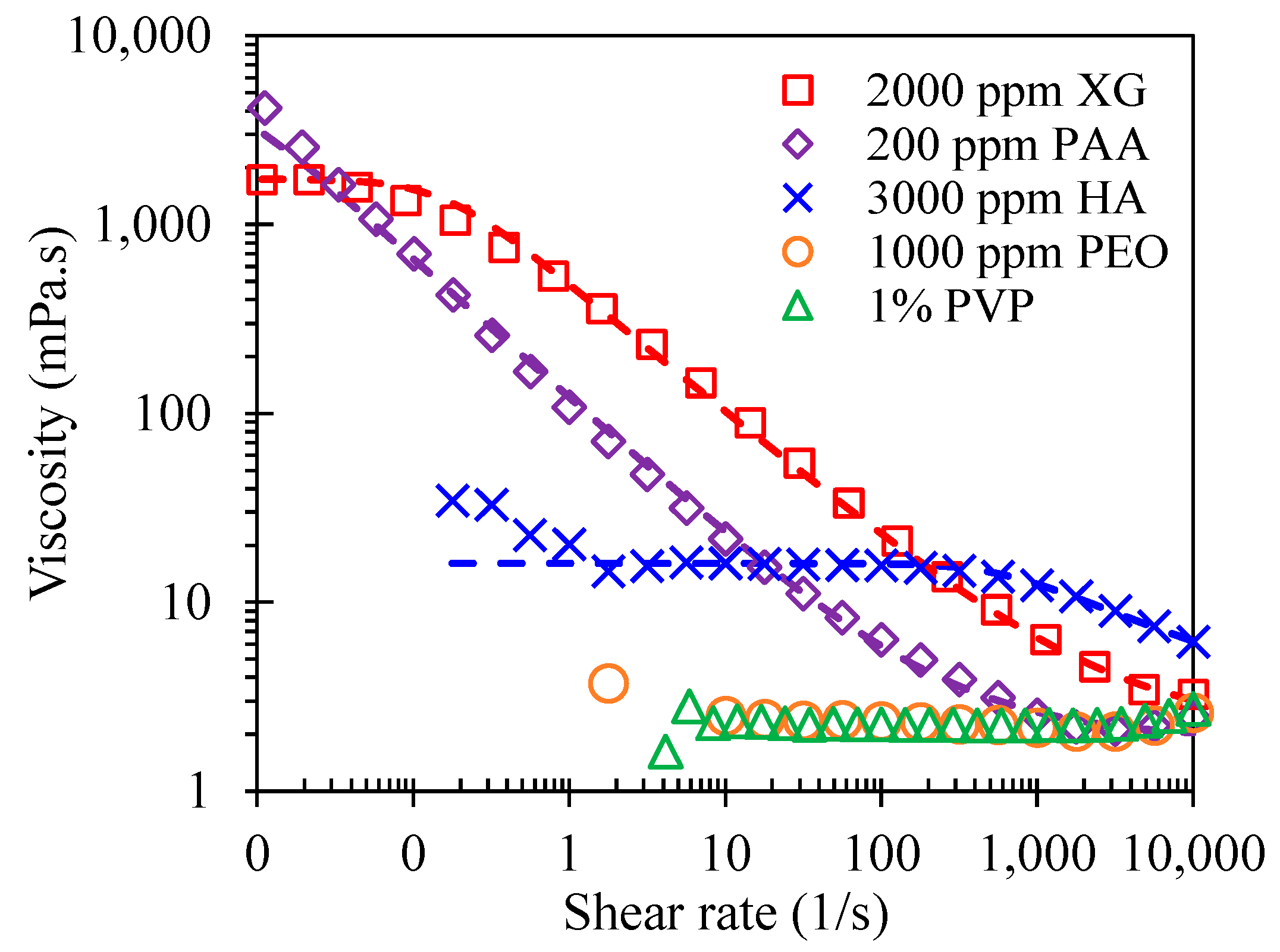
2.1. Materials
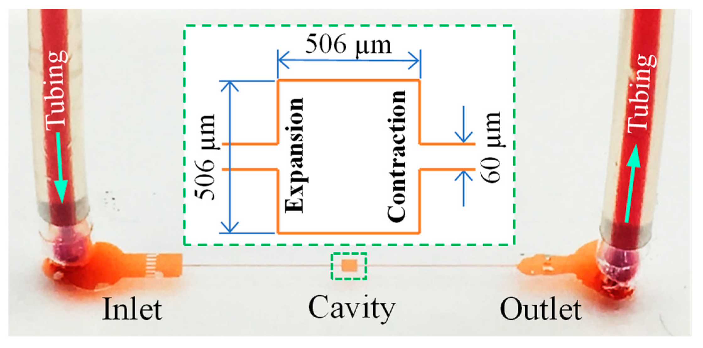
2.2. Methods
3. Results
3.1. Fluid Rheological Effects on the Cavity Flow
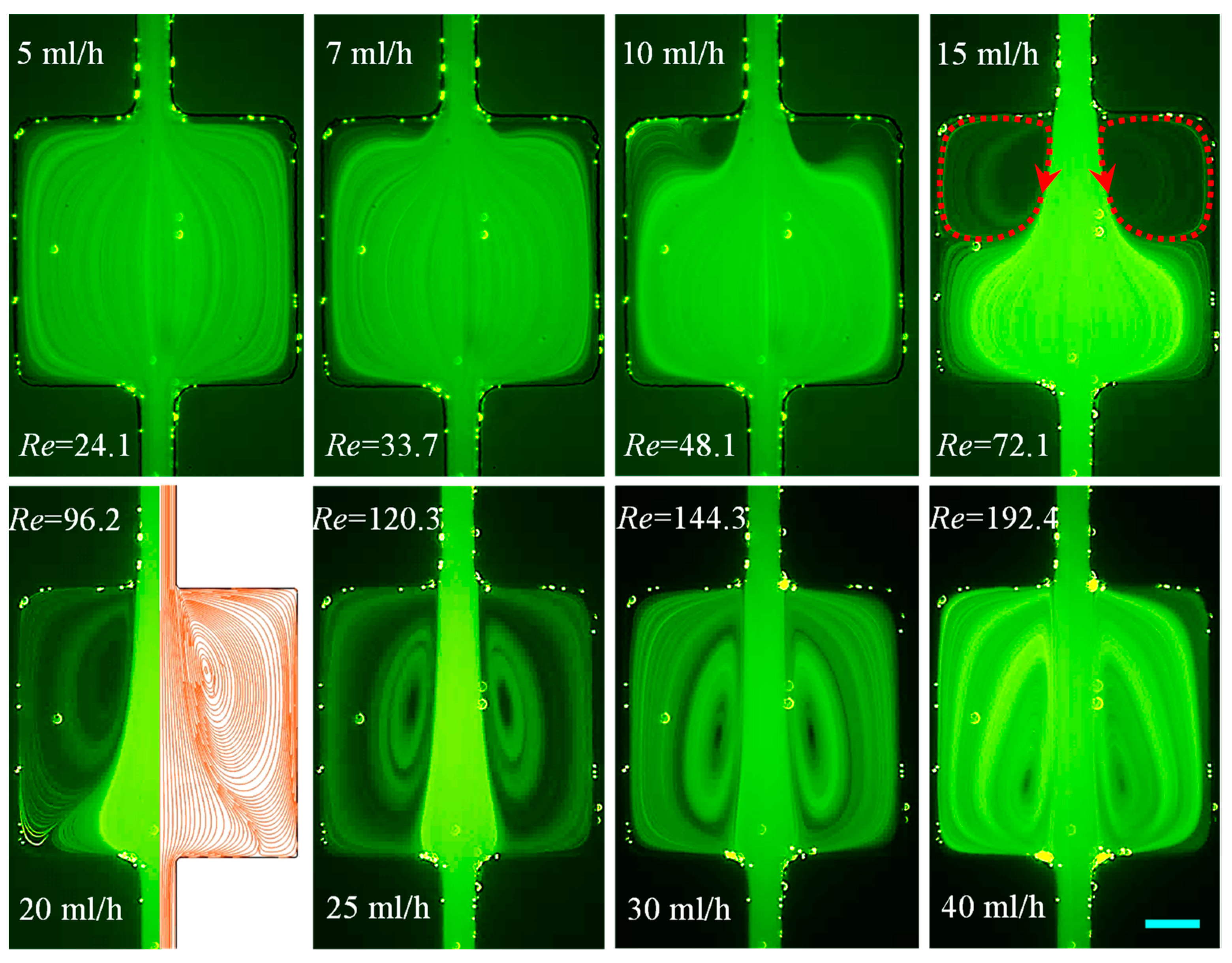
3.1.1. DI Water: Effects of Fluid Inertia
3.1.2. PVP Solution: Effects of Fluid Elasticity Along with Inertia
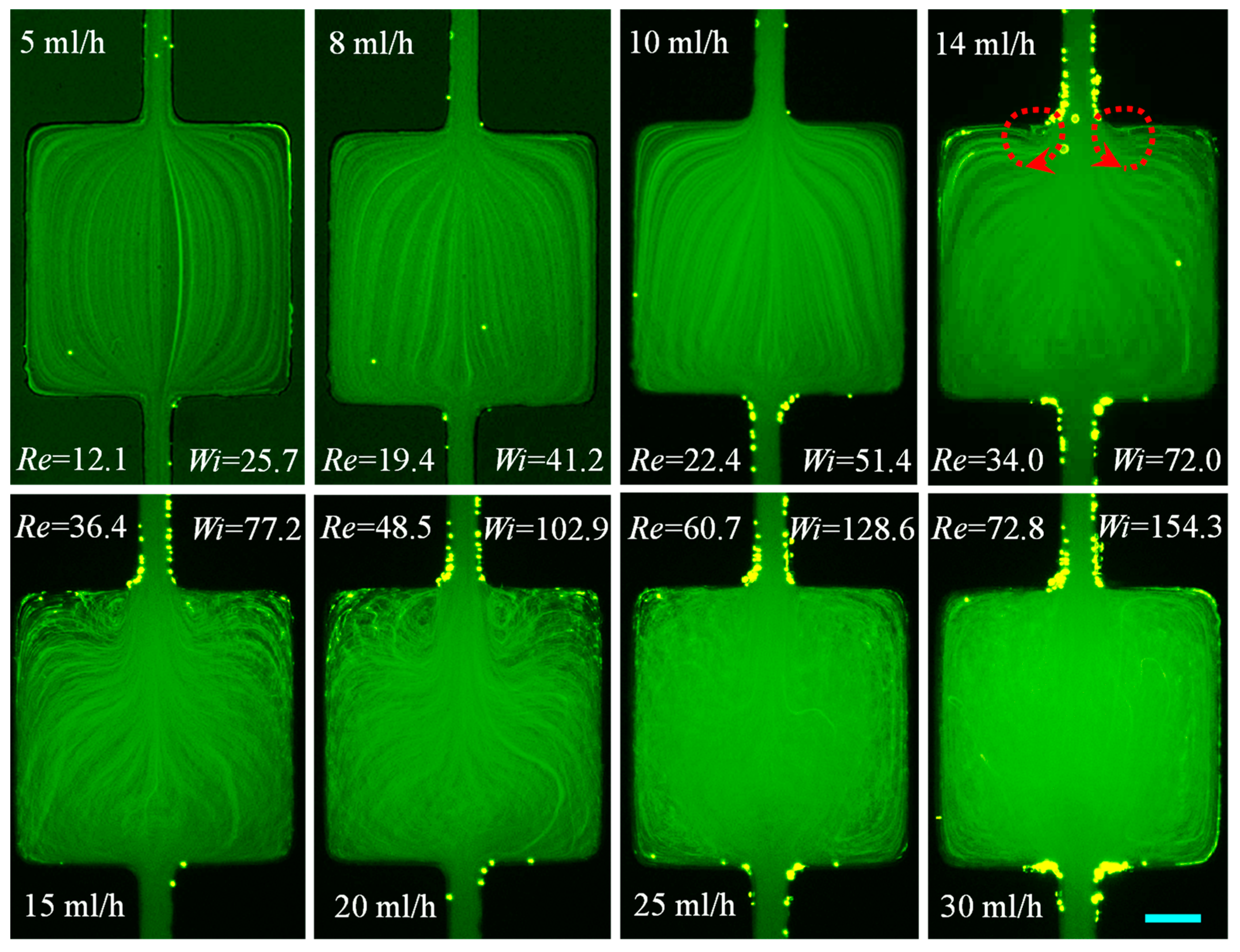
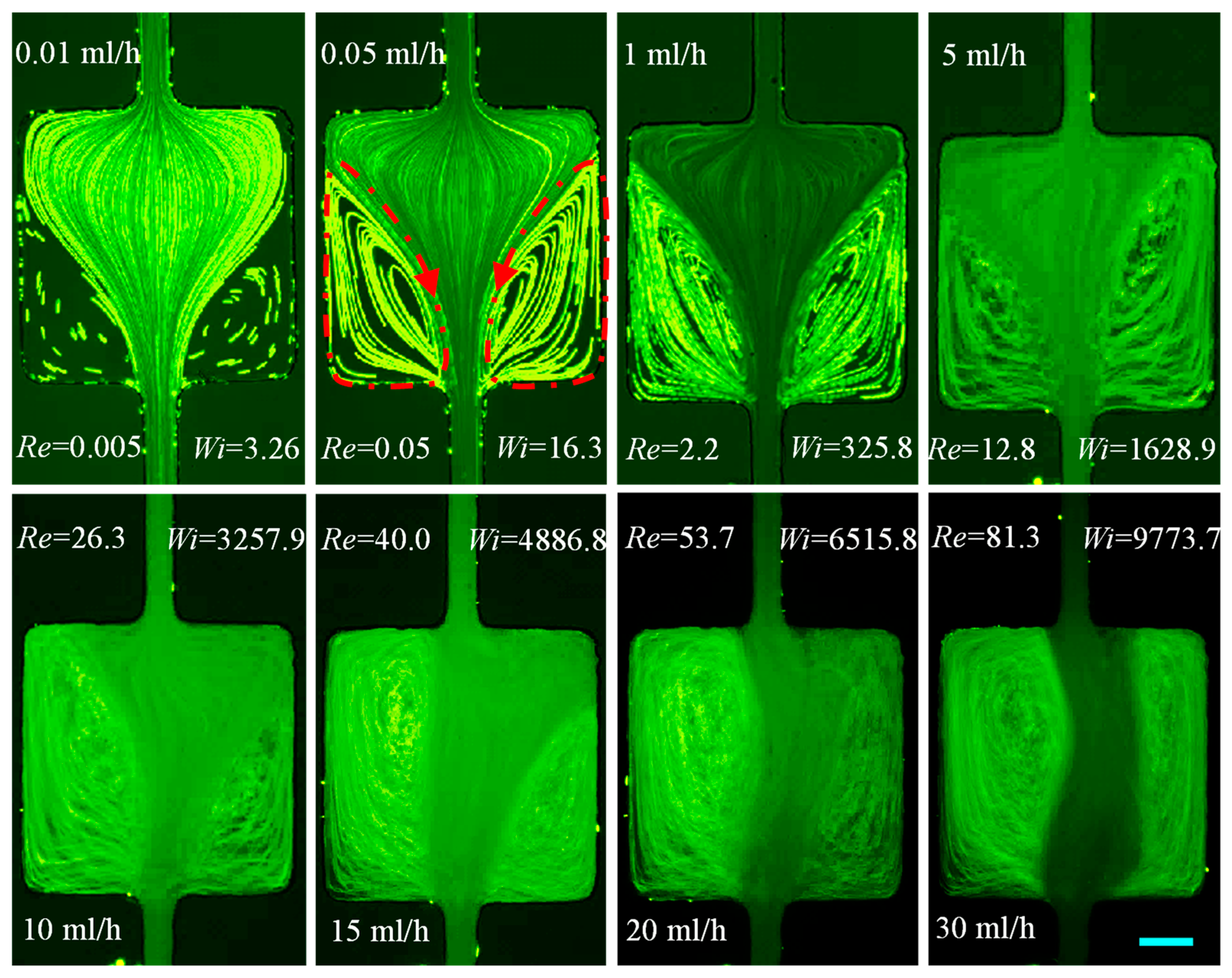
3.1.3. XG Solution: Effects of Fluid Shear Thinning Along with Inertia
3.1.4. HA Solution: Effects of Weak Elasticity and Mild Shear Thinning Along with Inertia
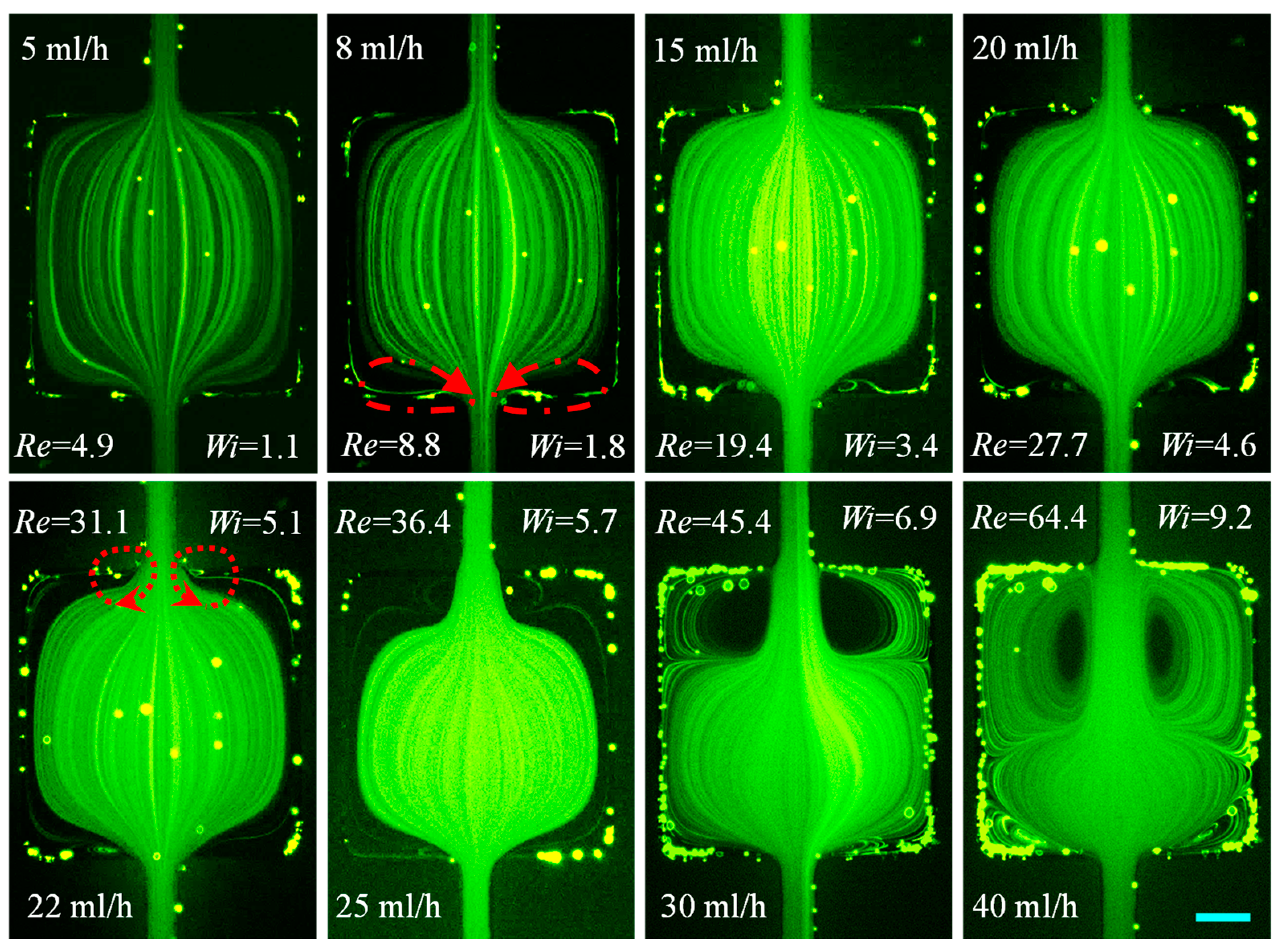
3.1.5. PEO Solution: Effects of Mild Elasticity and Weak Shear Thinning Along with Inertia
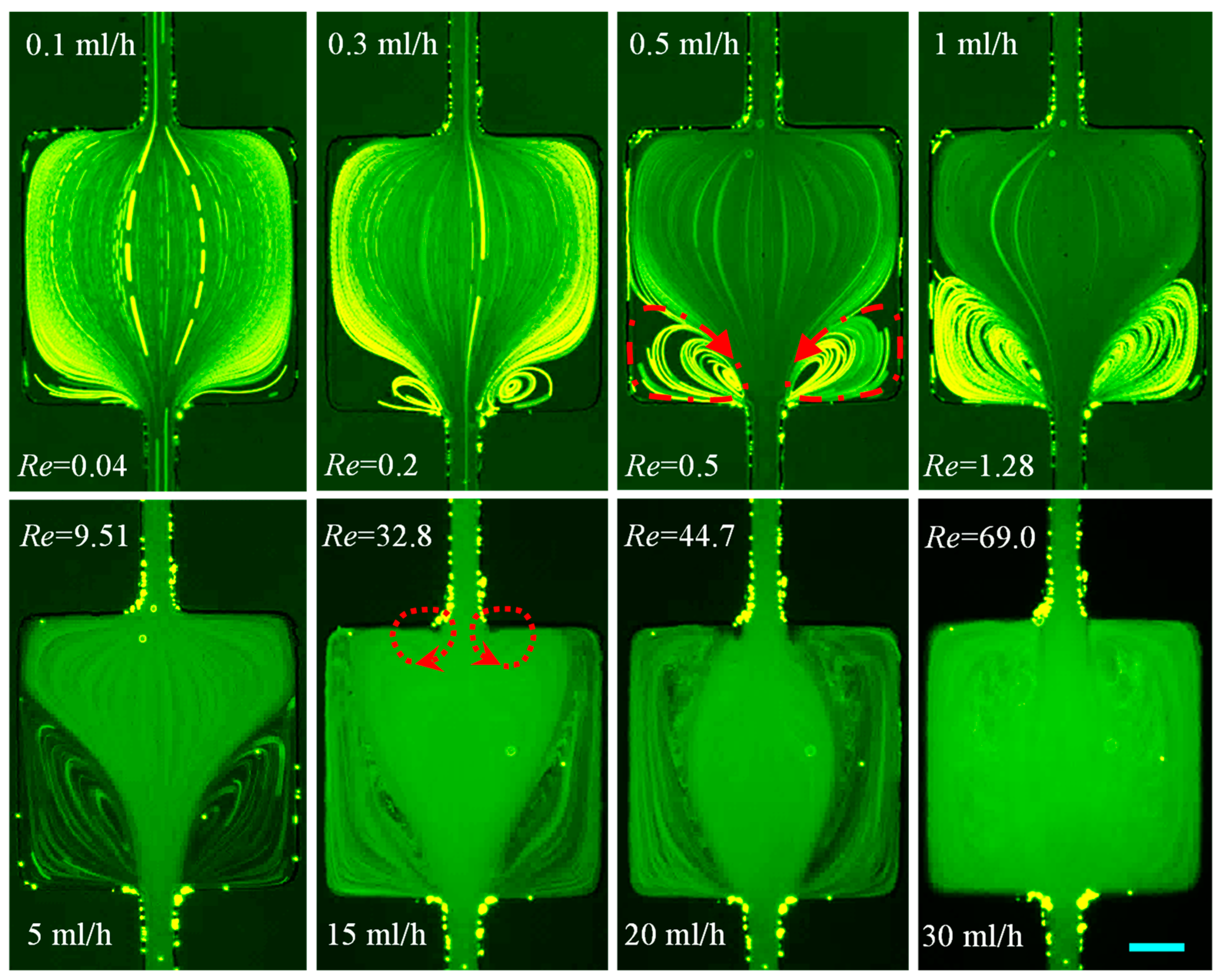
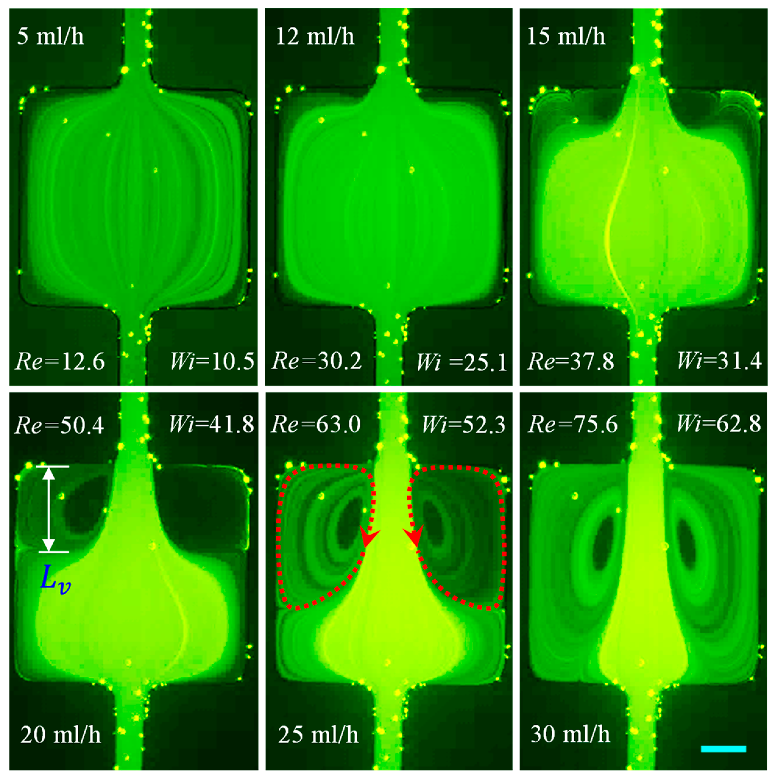
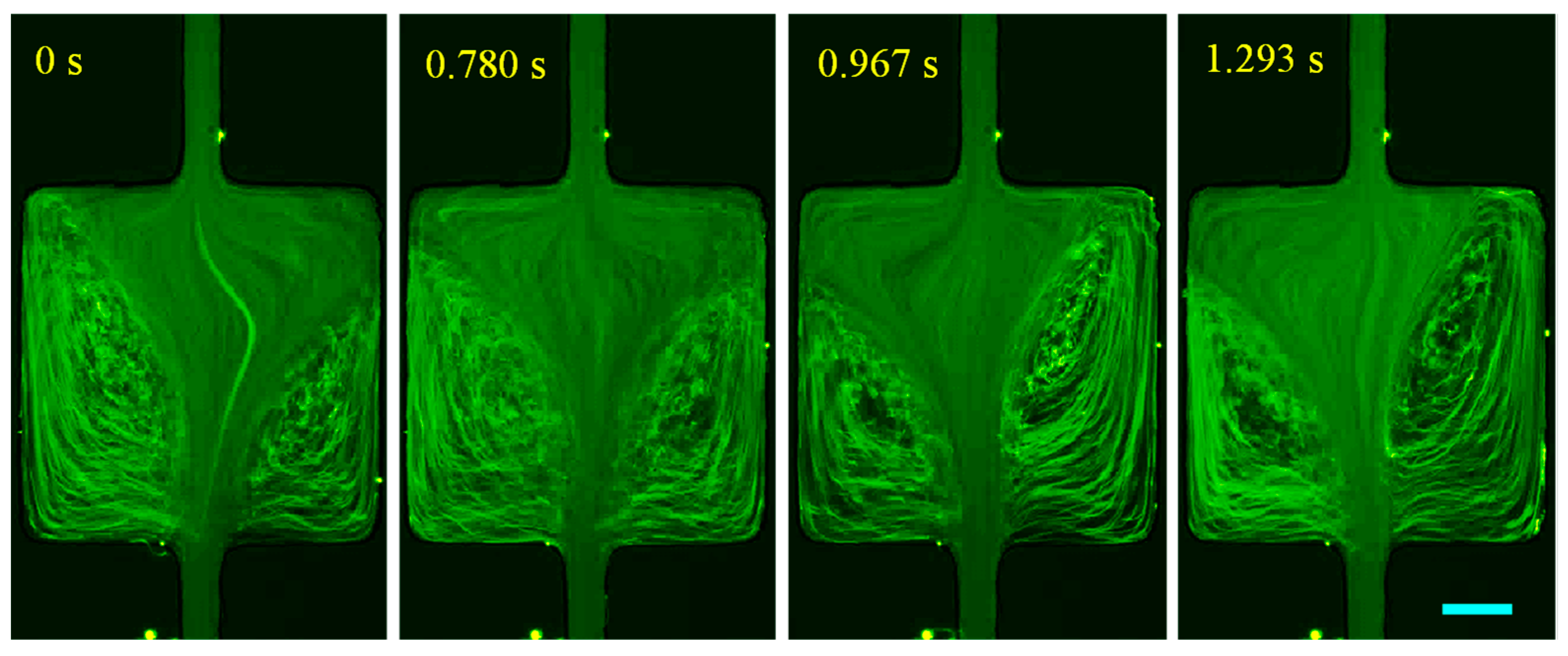
3.1.6. PAA Solution: Effects of Strong Elasticity and Strong Shear Thinning and Inertia
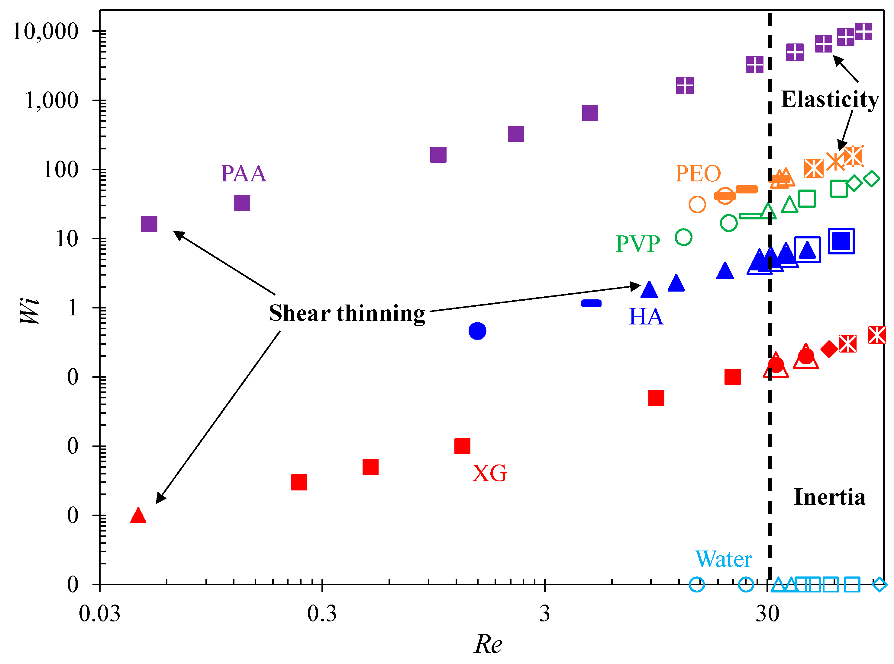
3.2. Summary of the Cavity Flow Pattern
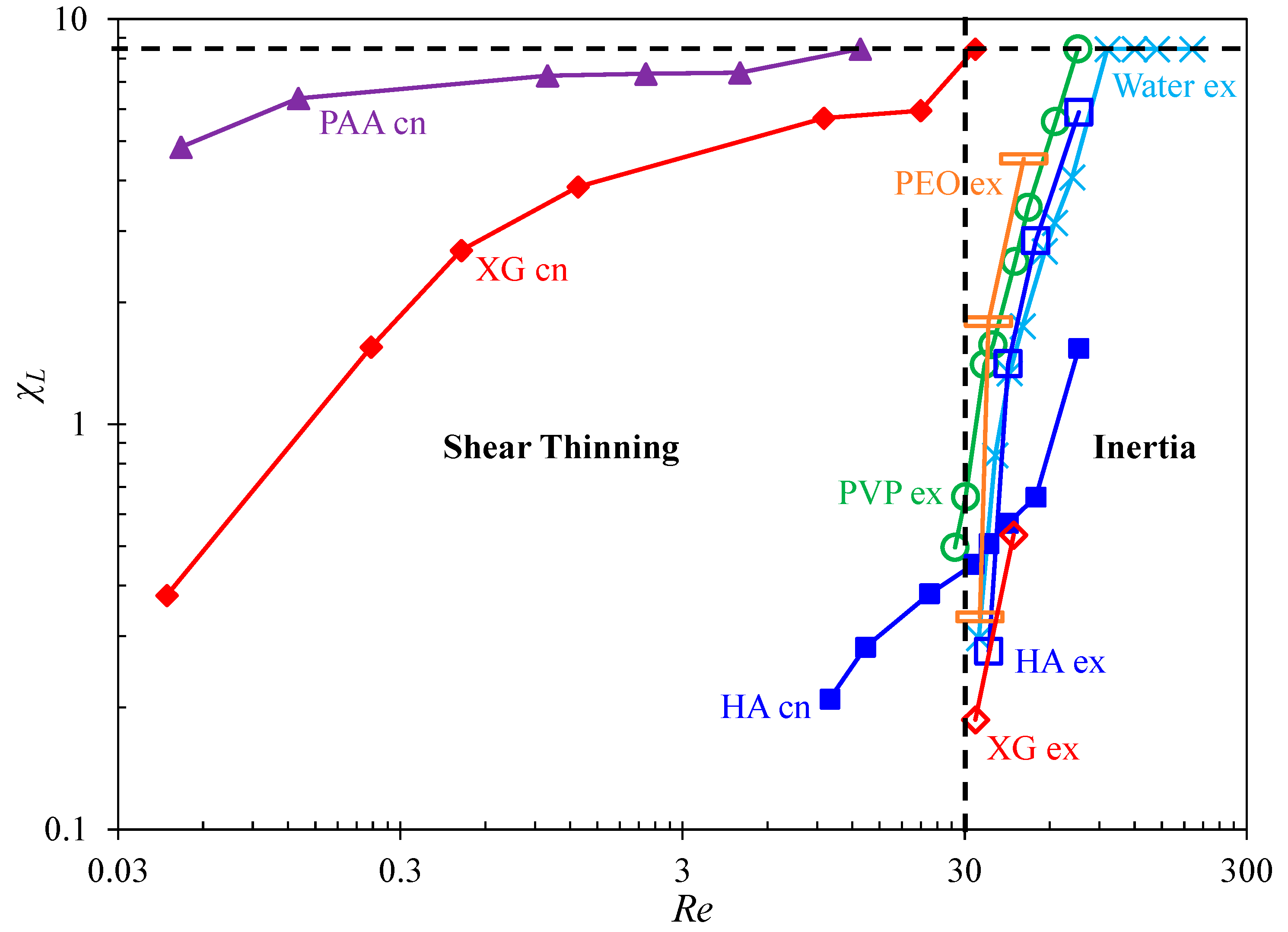
3.3. Summary of the Vortex Development
4. Conclusions
Author Contributions
Funding
Conflicts of Interest
References
- Clarkson, C.R.; Haghshenas, B.; Ghanizadeh, A.; Qanbari, F.; Williams-Kovacs, J.D.; Riazi, N.; Debuhr, C.; Deglint, H.J. Nanopores to megafractures: Current challenges and methods for shale gas reservoir and hydraulic fracture characterization. J. Nat. Gas Sci. Eng. 2016, 31, 612–657. [Google Scholar] [CrossRef]
- Barbati, A.C.; Desroches, J.; Robisson, A.; McKinley, G.H. Complex fluids and hydraulic fracturing. Annu. Rev. Chem. Biomol. Eng. 2016, 7, 415–453. [Google Scholar] [CrossRef] [PubMed] [Green Version]
- Roote, D.S. Technology Status Report Insitu Flushing. Ground-Water Remediation Technologies Analysis Center, 1998. Available online: http://www.gwrtac.org (accessed on 16 July 2021).
- Anbari, A.; Chien, H.T.; Datta, S.S.; Deng, W.; Weitz, D.A.; Fan, J. Microfluidic model porous media: Fabrication and applications. Small 2018, 14, 1703575. [Google Scholar] [CrossRef]
- Galindo-Rosales, F.J.; Campo-Deano, L.; Pinho, F.T.; van Bokhorst, E.; Hamersma, P.J.; Oliveira, M.S.N.; Alves, M.A. Microfluidic systems for the analysis of viscoelastic fluid flow phenomena in porous media. Microfluid. Nanofluid. 2012, 12, 485–498. [Google Scholar] [CrossRef] [Green Version]
- Browne, C.A.; Shih, A.; Datta, S.S. Pore-scale flow characterization of polymer solutions in microfluidic porous media. Small 2020, 16, 1903944. [Google Scholar] [CrossRef] [PubMed] [Green Version]
- Groisman, A.; Enzelberger, M.; Quake, S. Microfluidic memory and control devices. Science 2003, 300, 955–958. [Google Scholar] [CrossRef] [PubMed] [Green Version]
- Groisman, A.; Quake, S.R. A microfluidic rectifier: Anisotropic flow resistance at low Reynolds numbers. Phys. Rev. Lett. 2004, 92, 094501. [Google Scholar] [CrossRef] [Green Version]
- Gan, H.Y.; Lam, Y.C.; Nguyen, N.T. Polymer-based device for efficient mixing of viscoelastic fluids. Appl. Phys. Lett. 2006, 88, 224103. [Google Scholar]
- Gan, H.Y.; Lam, Y.C.; Nguyen, N.T.; Tam, K.C.; Yang, C. Efficient mixing of viscoelastic fluids in a microchannel at low Reynolds number. Microfluid. Nanofluid. 2007, 3, 101–108. [Google Scholar] [CrossRef]
- D’Avino, G.; Greco, F.; Maffettone, P.L. Particle migration due to viscoelasticity of the suspending liquid and its relevance in microfluidic devices. Annu. Rev. Fluid Mech. 2017, 49, 341–360. [Google Scholar] [CrossRef]
- Liu, C.; Hu, G. High-throughput particle manipulation based on hydrodynamic effects in microchannels. Micromachines 2017, 8, 73. [Google Scholar] [CrossRef] [Green Version]
- Lu, X.; Liu, C.; Hu, G.; Xuan, X. Particle manipulations in non-Newtonian microfluidics: A review. J. Colloid Interf. Sci. 2017, 500, 182–201. [Google Scholar] [CrossRef] [PubMed] [Green Version]
- Haward, S.J. Microfluidic extensional rheometry using stagnation point flow. Biomicrofluid 2016, 10, 043401. [Google Scholar] [CrossRef] [Green Version]
- Zhang, J.; Yan, S.; Yuan, D.; Alici, G.; Nguyen, N.T.; Warkiani, M.E.; Li, W. Fundamentals and applications of inertial microfluidics: A review. Lab Chip 2016, 16, 10–34. [Google Scholar] [CrossRef] [Green Version]
- Tian, F.; Feng, Q.; Chen, Q.; Liu, C.; Li, T.; Sun, J. Manipulation of bio-micro/nanoparticles in non-Newtonian microflows. Microfluid. Nanofluid. 2019, 23, 68. [Google Scholar] [CrossRef]
- Stoecklein, D.; Di Carlo, D. Nonlinear microfluidics. Anal. Chem. 2019, 91, 296–314. [Google Scholar]
- Zhou, J.; Papautsky, I. Viscoelastic microfluidics: Progress and challenges. Microsyst. Nanoeng. 2020, 6, 113. [Google Scholar] [CrossRef]
- Cha, S.; Kang, K.; You, J.B.; Im, S.G.; Kim, Y.; Kim, J.M. Hoop stress-assisted three-dimensional particle focusing under viscoelastic flow. Rheol. Acta 2014, 53, 927–933. [Google Scholar] [CrossRef]
- Yuan, D.; Zhang, J.; Yan, S.; Pan, C.; Alici, G.; Nguyen, N.T.; Li, W. Dean-flow-coupled elasto-inertial three-dimensional particle focusing under viscoelastic flow in a straight channel with asymmetrical expansion-contraction cavity arrays. Biomicrofluidics 2015, 9, 044108. [Google Scholar] [CrossRef] [Green Version]
- Fan, L.L.; Wu, X.; Zhang, H.; Zhao, Z.; Zhe, J.; Zhao, L. Continuous sheath-free focusing of microparticles in viscoelastic and Newtonian fluids. Microfluid. Nanofluid. 2019, 23, 17. [Google Scholar] [CrossRef]
- Hur, S.C.; Mach, A.J.; Di Carlo, D. High-throughput size-based rare cell enrichment using microscale vortices. Biomicrofluidics 2011, 5, 1–10. [Google Scholar] [CrossRef] [Green Version]
- Haddadi, H.; Di Carlo, D. Inertial flow of a dilute suspension over cavities in a microchannel. J. Fluid Mech. 2017, 811, 436–467. [Google Scholar] [CrossRef]
- Jiang, M.; Qian, S.; Liu, Z. Fully resolved simulation of single-particle dynamics in a microcavity. Microfluid. Nanofluid. 2018, 22, 144. [Google Scholar] [CrossRef]
- Zhou, J.; Kasper, S.; Papautsky, I. Enhanced size-dependent trapping of particles using microvortices. Microfluid. Nanofluid. 2013, 15, 611–623. [Google Scholar] [CrossRef] [Green Version]
- Shen, F.; Xue, S.; Xu, M.; Pang, Y.; Liu, Z. Experimental study of single-particle trapping mechanisms into microcavities using microfluidics. Phys. Fluids 2019, 31, 042002. [Google Scholar]
- Paiè, P.; Che, J.; Di Carlo, D. Effect of reservoir geometry on vortex trapping of cancer cells. Microfluid. Nanofluid. 2017, 21, 104. [Google Scholar] [CrossRef]
- Khojah, R.; Stoutamore, R.; Di Carlo, D. Size-tunable microvortex capture of rare cells. Lab Chip 2017, 17, 2542–2549. [Google Scholar] [CrossRef]
- Wang, X.; Zhou, J.; Papautsky, I. Vortex-aided inertial microfluidic device for continuous particle separation with high size-selectivity, efficiency, and purity. Biomicrofluidics 2013, 7, 044119. [Google Scholar] [CrossRef] [PubMed] [Green Version]
- Dhar, M.; Wong, J.; Karimi, A.; Che, J.; Renier, C.; Matsumoto, M.; Triboulet, M.; Garon, E.B.; Goldman, J.W.; Rettig, M.B.; et al. High efficiency vortex trapping of circulating tumor cells. Biomicrofluidics 2015, 9, 064116. [Google Scholar] [CrossRef] [PubMed]
- Che, J.; Yu, V.; Garon, E.B.; Goldman, J.W.; Di Carlo, D. Biophysical isolation and identification of circulating tumor cells. Lab Chip 2017, 17, 1452–1461. [Google Scholar] [CrossRef] [PubMed] [Green Version]
- Haddadi, H.; Naghsh-Nilchi, H.; Di Carlo, D. Separation of cancer cells using vortical microfluidic flows. Biomicrofluidics 2018, 12, 014112. [Google Scholar] [CrossRef]
- Raihan, M.K.; Li, D.; Kummetz, A.J.; Song, L.; Yu, L. Vortex trapping and separation of particles in shear thinning fluids. Appl. Phys. Lett. 2020, 116, 183701. [Google Scholar]
- Shen, F.; Xiao, P.; Liu, Z. Microparticle image velocimetry (μPIV) study of microcavity flow at low Reynolds number. Microfluid. Nanofluid. 2015, 19, 403–417. [Google Scholar] [CrossRef]
- Jagdale, P.P.; Li, D.; Shao, X.; Bostwick, J.B.; Xuan, X. Fluid rheological effects on the flow of polymer solutions in a contraction-expansion microchannel. Micromachines 2020, 11, 278. [Google Scholar] [CrossRef] [PubMed] [Green Version]
- Boger, D.V. Viscoelastic flows through contractions. Ann. Rev. Fluid Mech. 1987, 19, 157–182. [Google Scholar] [CrossRef]
- White, S.A.; Gotsis, A.D.; Baird, D.G. Review of the entry flow problem: Experimental and numerical. J. Non-Newton. Fluid Mech. 1987, 24, 121–160. [Google Scholar] [CrossRef]
- Oliveira, M.S.N.; Alves, M.A.; Pinho, F.T.; McKinley, G.H. Viscous flow through microfabricated hyperbolic contractions. Exp. Fluids 2007, 43, 437–451. [Google Scholar]
- Galindo-Rosales, F.J.; Campo-Deaño, L.; Sousa, P.C.; Ribeiro, V.M.; Oliveira, M.S.N.; Alves, M.A.; Pinho, F.T. Viscoelastic instabilities in micro-scale flows. Exp. Therm. Fluid Sci. 2014, 59, 128–139. [Google Scholar] [CrossRef] [Green Version]
- Walters, K.; Rawlinson, D.M. On some contraction flows for Boger fluids. Rheol. Acta 1982, 21, 547–552. [Google Scholar]
- Evans, R.E.; Walters, K. Flow characteristics associated with abrupt changes in geometry in the case of highly elastic liquids. J. Non-Newton. Fluid Mech. 1986, 20, 11–29. [Google Scholar]
- Chiba, K.; Sakatani, T.; Nakamura, K. Anomalous flow patterns in viscoelastic entry flow through a planar contraction. J. Non-Newton. Fluid Mech. 1990, 36, 193–203. [Google Scholar]
- Nigen, S.; Walters, K. Viscoelastic contraction flows: Comparison of axisymmetric and planar configurations. J. Non-Newton. Fluid Mech. 2002, 102, 343–359. [Google Scholar] [CrossRef]
- Poole, R.J.; Alves, M.A.; Oliveira, P.J.; Pinho, F.T. Plane sudden expansion flows of viscoelastic liquids. J. Non-Newton. Fluid Mech. 2007, 146, 79–91. [Google Scholar] [CrossRef] [Green Version]
- Oliveira, M.S.N.; Rodd, L.E.; McKinley, G.H.; Alves, M.A. Simulations of extensional flow in microrheometric devices. Microfluid. Nanofluid. 2008, 5, 809–826. [Google Scholar] [CrossRef] [Green Version]
- Rodd, L.E.; Scott, T.P.; Boger, D.V.; Cooper-White, J.J.; McKinley, G.H. The inertio-elastic planar entry flow of low-viscosity elastic fluids in micro-fabricated geometries. J. Non-Newton. Fluid Mech. 2005, 129, 1–22. [Google Scholar] [CrossRef] [Green Version]
- Rodd, L.E.; Cooper-White, J.J.; Boger, D.V.; McKinley, G.H. Role of the elasticity number in the entry flow of dilute polymer solutions in micro-fabricated contraction geometries. J. Non-Newton. Fluid Mech. 2007, 143, 170–191. [Google Scholar] [CrossRef]
- Rodd, L.E.; Lee, D.; Ahn, K.H.; Cooper-White, J.J. The importance of downstream events in microfluidic viscoelastic entry flows: Consequences of increasing the constriction length. J. Non-Newton. Fluid Mech. 2010, 165, 1189–1203. [Google Scholar] [CrossRef]
- Haward, S.J.; Page, J.; Zaki, T.A.; Shen, A.Q. Phase diagram for viscoelastic Poiseuille flow over a wavy surface. Phys. Fluids 2018, 30, 113101. [Google Scholar] [CrossRef] [Green Version]
- Wu, S.; Raihan, M.K.; Song, L.; Shao, X.; Bostwick, J.B.; Yu, L.; Pan, X.; Xuan, X. Polymer effects on viscoelastic fluid flows in a planar constriction microchannel. J. Non-Newton. Fluid Mech. 2021, 290, 104508. [Google Scholar] [CrossRef]
- Campo-Deañoa, L.; Galindo-Rosales, F.J.; Pinho, F.T.; Alves, M.A.; Oliveira, M.S.N. Flow of low viscosity Boger fluids through a microfluidic hyperbolic contraction. J. Non-Newton. Fluid Mech. 2011, 166, 1286–1296. [Google Scholar] [CrossRef] [Green Version]
- Lanzaro, A.; Yuan, X.F. Effects of contraction ratio on non-linear dynamics of semi-dilute, highly polydisperse PAAm solutions in microfluidics. J. Non-Newton. Fluid Mech. 2011, 166, 1064–1075. [Google Scholar] [CrossRef]
- Lanzaro, A.; Li, Z.; Yuan, X.F. Quantitative characterization of high molecular weight polymer solutions in microfluidic hyperbolic contraction flow. Microfluid. Nanofluid. 2015, 18, 819–828. [Google Scholar] [CrossRef]
- Sousa, P.C.; Pinho, F.T.; Oliveira, M.S.N.; Alves, M.A. Extensional flow of blood analog solutions in microfluidic devices. Biomicrofluidic 2011, 5, 014108. [Google Scholar] [CrossRef] [Green Version]
- Gulatia, S.; Muller, S.J.; Liepmanna, D. Direct measurements of viscoelastic flows of DNA in a 2:1 abrupt planar micro-contraction. J. Non-Newton. Fluid Mech. 2008, 155, 51–66. [Google Scholar] [CrossRef]
- Hemminger, O.L.; Boukany, P.E.; Wang, S.; Lee, J.J. Flow pattern and molecular visualization of DNA solutions through a 4:1 planar micro-contraction. J. Non-Newton. Fluid Mech. 2010, 165, 1613–1624. [Google Scholar] [CrossRef]
- Miller, E.; Cooper-White, J.J. The effects of chain conformation in the microfluidic entry flow of polymer–surfactant systems. J. Non-Newton. Fluid Mech. 2009, 60, 22–30. [Google Scholar] [CrossRef]
- Matos, R.M.; Alves, M.A.; Pinho, F.T. Instabilities in micro-contraction flows of semi-dilute CTAB and CPyCl solutions: Rheology and flow instabilities. Exp. Fluids 2019, 60, 145. [Google Scholar] [CrossRef]
- Bird, R.B.; Armstrong, R.C.; Hassager, O. Dynamics of Polymeric Liquids, Vol. 1; Wiley-Interscience: Hoboken, NJ, USA, 1987. [Google Scholar]
- Hidema, R.; Oka, T.; Komoda, Y.; Suzuki, H. Effects of flexibility and entanglement of sodium hyaluronate in solutions on the entry flow in micro abrupt contraction-expansion channels. Phys. Fluids 2019, 31, 072005. [Google Scholar] [CrossRef]
- Kawale, D.; Marques, E.; Zitha, P.L.J.; Kreutzer, M.T.; Rossen, W.R.; Boukany, P.E. Elastic instabilities during the flow of hydrolyzed polyacrylamide solution in porous media: Effect of pore-shape and salt. Soft Matt. 2017, 13, 765–775. [Google Scholar] [CrossRef]
- Ekanem, E.M.; Berg, S.; De, S.; Fadili, A.; Bultreys, T.; Rücker, M.; Southwick, J.; Crawshaw, J.; Luckham, P.F. Signature of elastic turbulence of viscoelastic fluid flow in a single pore throat. Phys. Rev. E 2020, 101, 042605. [Google Scholar]
- De Souza Mendes, P.R.; Naccache, M.F.; Varges, P.R.; Marchesini, F.H. Flow of viscoplastic liquids through axisymmetric expansions-contractions. J. Non-Newton. Fluid Mech. 2007, 142, 207–217. [Google Scholar] [CrossRef]
- Varges, P.R.; Fonseca, B.S.; de Souza Mendes, P.R.; Naccache, M.F.; de Miranda, C.R. Flow of yield stress materials through annular abrupt expansion–contractions. Phys. Fluids 2020, 32, 083101. [Google Scholar] [CrossRef]
- Hong, S.O.; Cooper-White, J.J.; Kim, J.M. Inertio-elastic mixing in a straight microchannel with side wells. Appl. Phys. Lett. 2016, 108, 13–17. [Google Scholar]
- Hong, S.O.; Park, K.; Kim, D.; Lee, S.S.; Lee, C.; Kim, J.M. Gear-shaped micromixer for synthesis of silica particles utilizing inertio-elastic flow instability. Lab Chip 2021, 21, 513–520. [Google Scholar] [CrossRef]
- Sasmal, C. Flow of wormlike micellar solutions through a long micropore with step expansion and contraction. Phys. Fluids 2020, 32, 013103. [Google Scholar] [CrossRef]
- Vasquez, P.A.; McKinley, G.H.; Cook, P.L. A network scission model for wormlike micellar solutions: I. Model formulation and viscometric flow predictions. J. Non-Newton. Fluid Mech. 2007, 14, 4122–4139. [Google Scholar]
- Browne, C.A.; Shih, A.; Datta, S.S. Bistability in the unstable flow of polymer solutions through pore constriction arrays. J. Fluid Mech. 2020, 890, A2. [Google Scholar] [CrossRef] [Green Version]
- Yuan, D.; Zhao, Q.; Yan, S.; Tang, S.Y.; Alici, G.; Zhang, J.; Li, W. Recent progress of particle migration in viscoelastic fluids. Lab Chip 2018, 18, 551–567. [Google Scholar] [CrossRef] [Green Version]
- James, D.F. Boger fluids. Annu. Rev. Fluid Mech. 2009, 41, 129–142. [Google Scholar] [CrossRef]
- Lindner, A.; Bonn, D.; Meunier, J. Viscous fingering in a shear-thinning fluid. Phys. Fluids 2000, 12, 256–261. [Google Scholar] [CrossRef]
- Lim, H.; Back, S.M.; Hwang, M.H.; Lee, D.H.; Choi, H.; Nam, J. Sheathless high-throughput circulating tumor cell separation using viscoelastic non-Newtonian fluid. Micromachines 2019, 10, 462. [Google Scholar] [CrossRef] [Green Version]
- Poole, R.J.; Escudier, M.P. Turbulent flow of viscoelastic liquids through an axisymmetric sudden expansion. J. Non-Newton. Fluid Mech. 2004, 117, 25–46. [Google Scholar] [CrossRef]
- Liu, C.; Xue, C.; Chen, X.; Shan, L.; Tian, Y.; Hu, G. Size-based separation of particles and cells utilizing viscoelastic effects in straight microchannels. Anal. Chem. 2015, 87, 6041–6048. [Google Scholar]
- Tirtaatmadja, V.; McKinley, G.H.; Cooper-White, J.J. Drop formation and breakup of low viscosity elastic fluids: Effects of molecular weight and concentration. Phys. Fluids 2006, 18, 043101. [Google Scholar] [CrossRef] [Green Version]
- Haward, S.J. Characterization of hyaluronic acid and synovial fluid in stagnation point elongational flow. Biopolymer 2014, 101, 287–305. [Google Scholar] [CrossRef] [PubMed]
- Mewis, J.; Wagner, N.J. Thixotropy. Adv. Colloid Interf. Sci. 2009, 147–148, 214–277. [Google Scholar] [CrossRef]
- Boi, S.; Mazzino, A.; Pralits, J.O. Minimal model for zero-inertia instabilities in shear-dominated non-Newtonian flows. Phys. Rev. E 2013, 88, 033007. [Google Scholar]
- Haase, A.S.; Wood, J.A.; Sprakel, L.M.J.; Lammertink, R.G.H. Inelastic non-Newtonian flow over heterogeneously slippery surfaces. Phys. Rev. E 2017, 95, 023105. [Google Scholar]
- Lim, H.; Nam, J.; Shin, S. Lateral migration of particles suspended in viscoelastic fluids in a microchannel flow. Microfluid. Nanofluid. 2014, 17, 683–692. [Google Scholar] [CrossRef]
- Sengupta, S.; De, S. Effect of Couette component on the stability of Poiseuille flow of a Bingham fluid–porous system: Modal and non-modal approaches. Phys. Fluids 2020, 32, 064103. [Google Scholar] [CrossRef]
- Hopkins, C.C.; Haward, S.J.; Shen, A.Q. Tristability in viscoelastic flow past side-by-side microcylinders. Phys. Rev. Lett. 2021, 126, 054501. [Google Scholar] [CrossRef]
- Shi, X.; Christopher, G.F. Growth of viscoelastic instabilities around linear cylinder arrays. Phys. Fluids 2016, 28, 124102. [Google Scholar] [CrossRef]
- Haward, S.J.; Toda-Peters, K.; Shen, A.Q. Steady viscoelastic flow around high-aspect-ratio, low-blockage-ratio microfluidic cylinders. J. Non-Newton. Fluid Mech. 2018, 254, 23–35. [Google Scholar] [CrossRef]
- Walkama, D.M.; Waisbord, N.; Guasto, J.S. Disorder suppresses chaos in viscoelastic flows. Phys. Rev. Lett. 2020, 124, 164501. [Google Scholar] [CrossRef] [PubMed] [Green Version]
- Poole, R.J.; Alves, M.A.; Oliveira, P.J. Purely elastic flow asymmetries. Phys. Rev. Lett. 2007, 99, 164503. [Google Scholar] [CrossRef]
- Oliveira, P.J. An exact solution for tube and slit flow of a FENE-P fluid. Acta Mech. 2002, 158, 157–167. [Google Scholar] [CrossRef] [Green Version]
- Kumar, M.; Aramideh, S.; Browne, C.A.; Datta, S.S.; Ardekani, A.M. Numerical investigation of multistability in the unstable flow of a polymer solution through porous media. Phys. Rev. Fluids 2021, 6, 033304. [Google Scholar] [CrossRef]


| Solution | (ms) | |||||
|---|---|---|---|---|---|---|
| DI Water | 1 | 1 | − | 1 | 0 | 0 |
| 10,000 ppm PVP | 2.1 | 2.1 | − | ≅1 | 0.61 | 0.83 |
| 2000 ppm XG | 1740 | 1.8 | 6.6 | 0.33 | ~0 | ~0 |
| 3000 ppm HA | 16 | 1.5 | 0.0018 | 0.62 | 0.067 | 0.20 |
| 1000 ppm PEO | 2.18 | 2.18 | − | ~1 | 1.5 * | 2.12 |
| 200 ppm PAA | 4900 | 2.1 | 151 | 0.25 | 95 ** | 123.64 |
Publisher’s Note: MDPI stays neutral with regard to jurisdictional claims in published maps and institutional affiliations. |
© 2021 by the authors. Licensee MDPI, Basel, Switzerland. This article is an open access article distributed under the terms and conditions of the Creative Commons Attribution (CC BY) license (https://creativecommons.org/licenses/by/4.0/).
Share and Cite
Raihan, M.K.; Jagdale, P.P.; Wu, S.; Shao, X.; Bostwick, J.B.; Pan, X.; Xuan, X. Flow of Non-Newtonian Fluids in a Single-Cavity Microchannel. Micromachines 2021, 12, 836. https://doi.org/10.3390/mi12070836
Raihan MK, Jagdale PP, Wu S, Shao X, Bostwick JB, Pan X, Xuan X. Flow of Non-Newtonian Fluids in a Single-Cavity Microchannel. Micromachines. 2021; 12(7):836. https://doi.org/10.3390/mi12070836
Chicago/Turabian StyleRaihan, Mahmud Kamal, Purva P. Jagdale, Sen Wu, Xingchen Shao, Joshua B. Bostwick, Xinxiang Pan, and Xiangchun Xuan. 2021. "Flow of Non-Newtonian Fluids in a Single-Cavity Microchannel" Micromachines 12, no. 7: 836. https://doi.org/10.3390/mi12070836
APA StyleRaihan, M. K., Jagdale, P. P., Wu, S., Shao, X., Bostwick, J. B., Pan, X., & Xuan, X. (2021). Flow of Non-Newtonian Fluids in a Single-Cavity Microchannel. Micromachines, 12(7), 836. https://doi.org/10.3390/mi12070836