
Process Intensification of Chemical Exchange Method for Boron Isotope Separation Using Micro-Channel Distillation Technology

Abstract
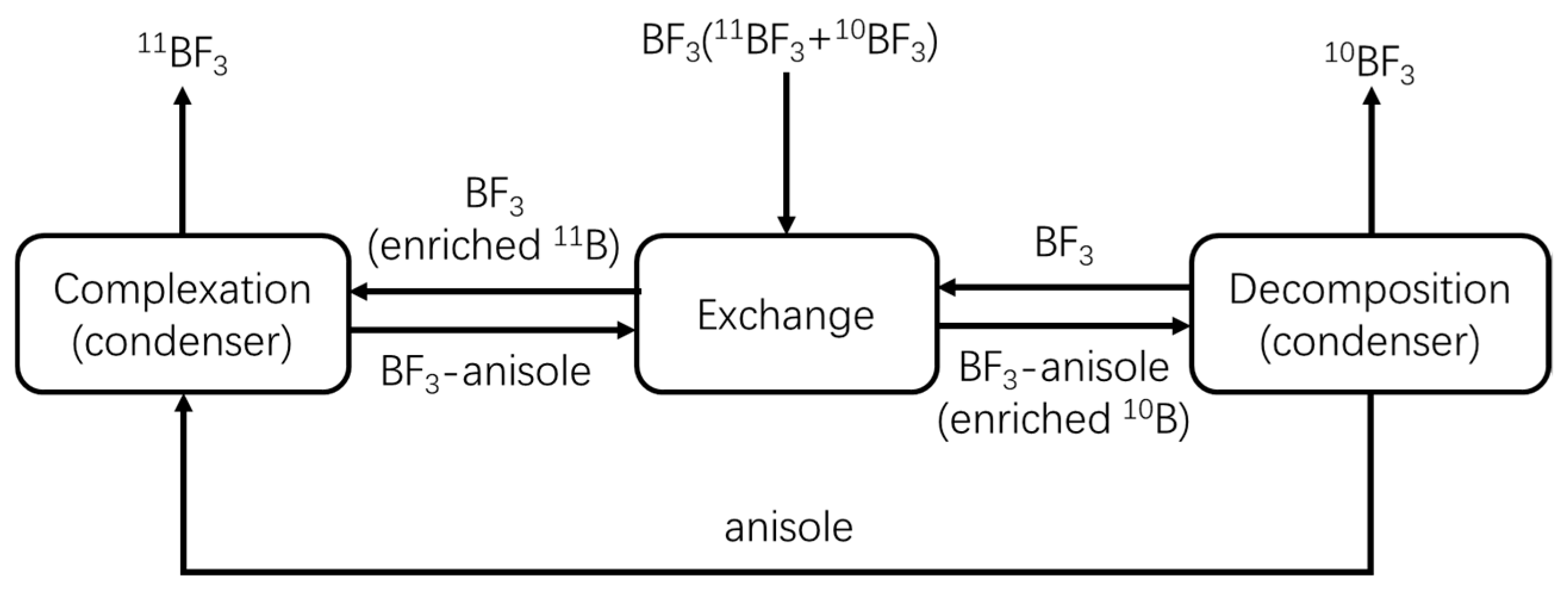
:1. Introduction
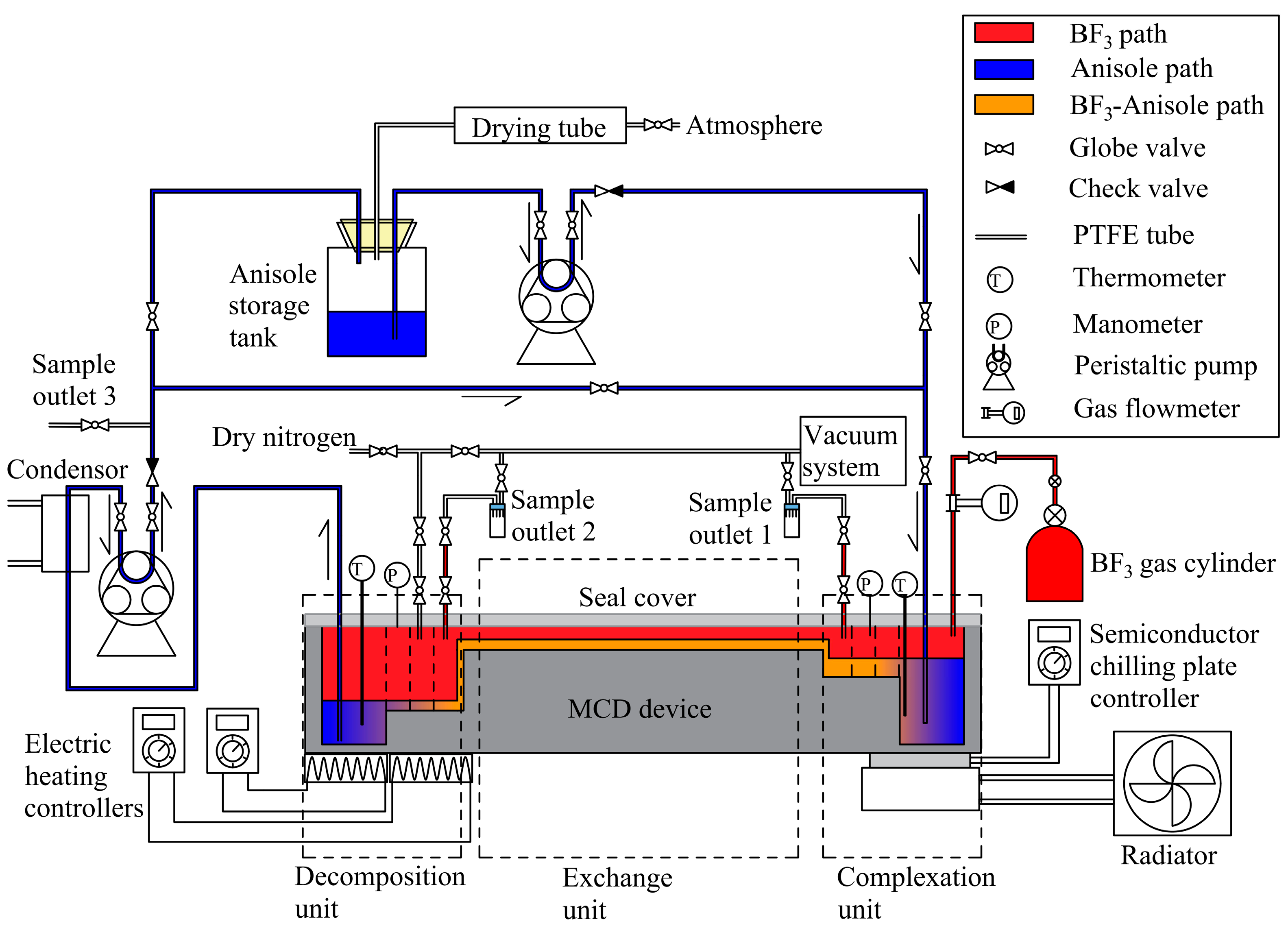
2. Experimental Procedure
2.1. Reagents and Apparatus
2.2. Dehydration and Purification of Anisole
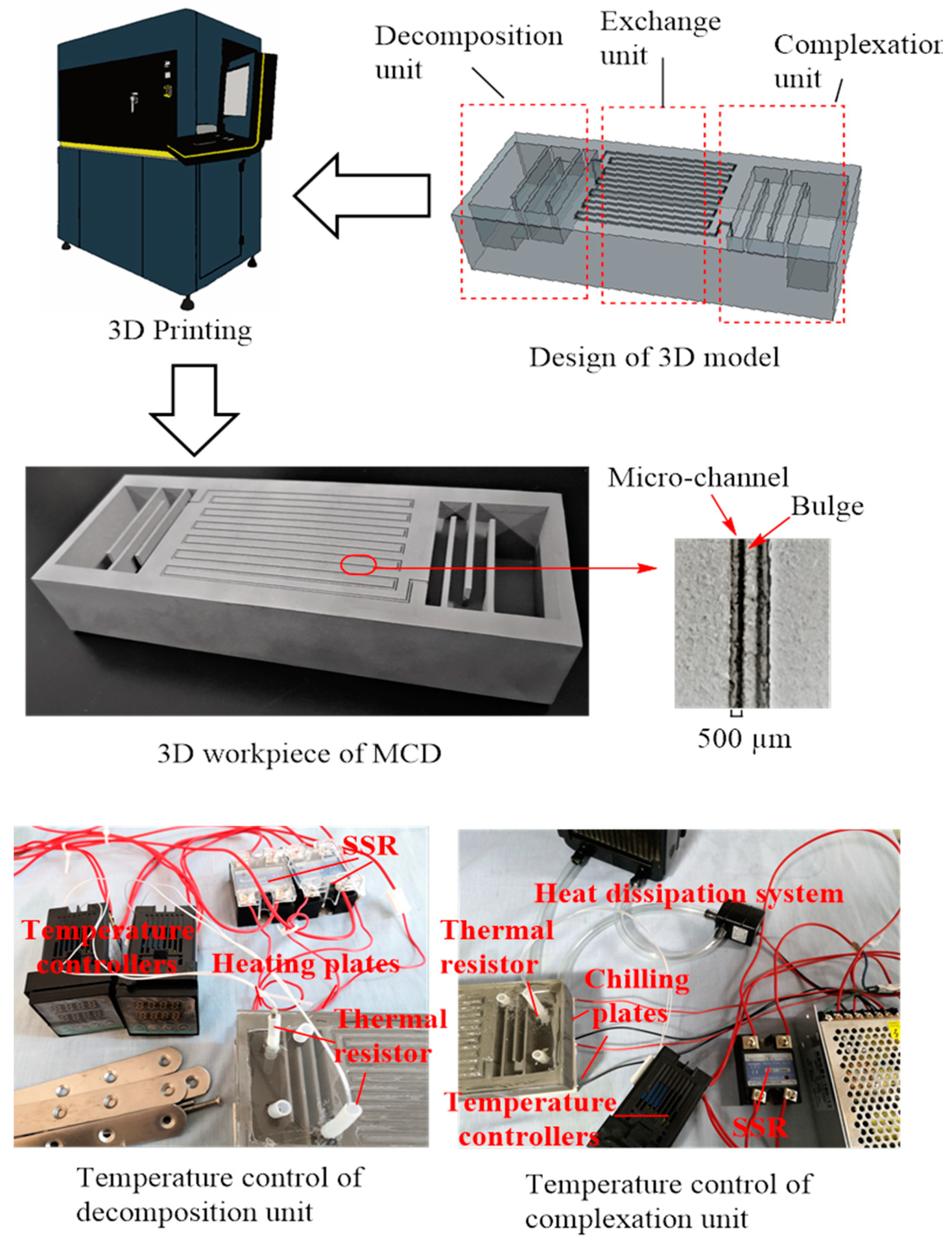
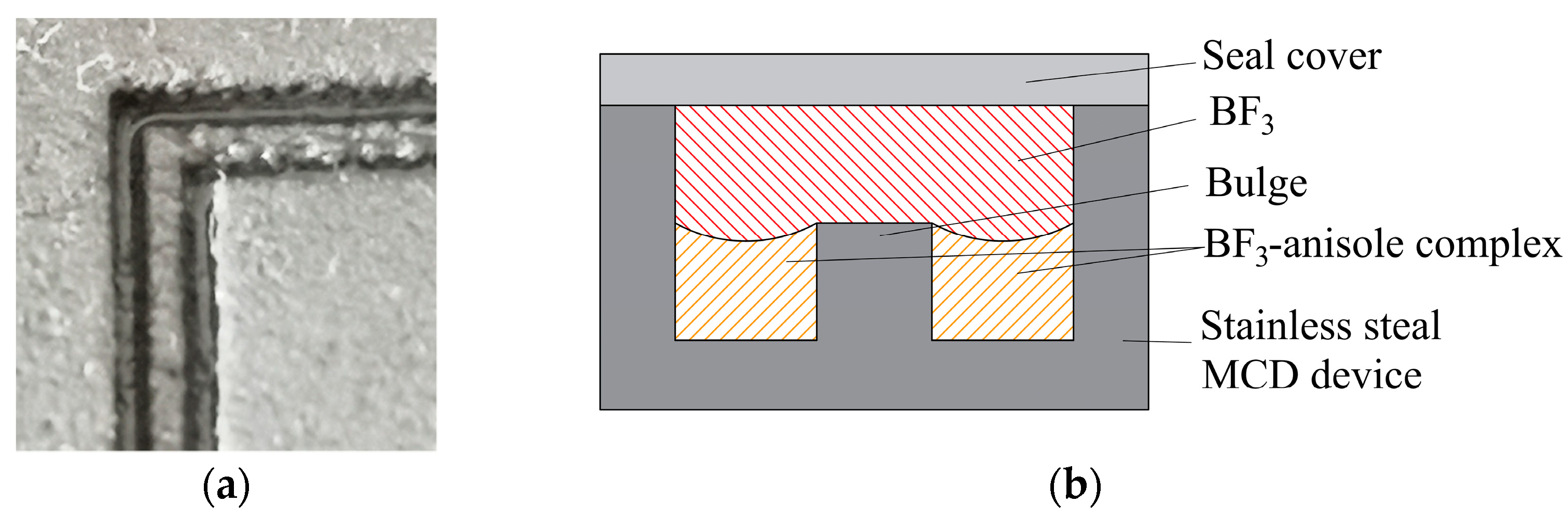
2.3. Manufacturing of the Micro-Distillation Device
2.3.1. Complexation Unit
2.3.2. Exchange Unit
2.3.3. Decomposition Unit
2.4. Determination of 11B/10B Isotope Ratio
3. Results and Discussions
3.1. Production of Micro-Channel Distillation in Total Reflux
3.1.1. Start-Up
3.1.2. Equilibrium Process
3.1.3. Sample Collection and Testing
3.2. Range of Flow Rate and Equilibrium Time
- The liquid level in the complexation unit could not pass through the serpentine micro-channel; otherwise, flooding would occur.
- The feed volume of the decomposition unit could not exceed the load of the heater. Although the heating temperature of the heater could be increased to accelerate the decomposition of the complex, excessive local temperatures would increase the chance of side reactions.
- The anisole in the decomposition unit could not be completely extracted; otherwise BF3 would overflow into the pump.
3.3. Testing of Height Equivalent to a Theoretical Plate
3.4. Effect on Flow Rate and Pressure
3.5. Residual Boron Content in the Steam of the Decomposition Unit Steam
4. Conclusions
Author Contributions
Funding
Institutional Review Board Statement
Informed Consent Statement
Data Availability Statement
Conflicts of Interest
Abbreviations
| MCD | Micro-channel distillation |
| HETP | Height of an equivalent theoretical plate |
| ICP-MS | Inductively coupled plasma mass spectrometry |
| CPS | Count per Second |
| PTFE | Polytetrafluoroethylene |
| SSR | Solid-state relay |
References
- Gubanova, N.V.; Tsygankova, A.R.; Zavjalov, E.L.; Romashchenko, A.V.; Orlov, Y.L. Biodistribution of 10B in Glioma Orthotopic Xenograft Mouse Model after Injection of L-para-Boronophenylalanine and Sodium Borocaptate. Biomedicines 2021, 9, 722. [Google Scholar] [CrossRef] [PubMed]
- Jie, H.; Luzin, V.; Zaman, M.; Abdulsalam, A.V.; Chae, K.H.; Choi, H.; Levchenko, V.; Nijhuis, A.; Kim, J.H.; Mustapić, M. Evaluation of isotopic boron (11B) for the fabrication of low activation Mg11B2 superconductor for next generation fusion magnets. J. Am. Ceram. Soc. 2020, 103, 5488–5495. [Google Scholar] [CrossRef]
- Healy, R.M.; Palko, A.A. Separation of Boron Isotopes. I. Boron Trihalide Addition Compounds. J. Chem. Phys. 1958, 28, 211–213. [Google Scholar] [CrossRef]
- Ol, T.; Tsukamoto, T.; Arai, H.; Kakihana, H. Boron isotope separation by ion-exchange chromatography using an anion-exchange resin in halide forms. J. Chromatogr. A 1988, 450, 343–352. [Google Scholar]
- Kuessner, M.L.; Gourgiotis, A.; Manhès, G.; Bouchez, J.; Zhang, X.; Gaillardet, J. Automated Analyte separation by Ion Chromatography using a Cobot Applied to Geological Reference Materials for Li Isotope Composition. Geostand. Geoanal. Res. 2019, 1, 57–67. [Google Scholar] [CrossRef]
- Zhou, F.; Zhang, J.; Bai, P.; Guo, X. Theoretical Calculation of Boron Isotopic Separation Factors in Ion-Exchange Chromatography. J. Chem. Eng. Data 2016, 62, 525–531. [Google Scholar] [CrossRef]
- Lyakhov, K.; Lee, H.J. New Experimental Setup for Boron Isotopes Separation by the Laser Assisted Retardation of Condensation Method. J. Nanosci. Nanotechnol. 2015, 15, 8502–8507. [Google Scholar] [CrossRef]
- Lyakhov, K.A.; Pechen, A.N. CO2 laser system design for efficient boron isotope separation by the method of selective laser-assisted retardation of condensation. Appl. Phys. B Lasers Opt. 2020, 126, 1–11. [Google Scholar] [CrossRef]
- Palko, A.A.; Healy, R.M.; Landau, L. Separation of Boron Isotopes. II. The BF3 Anisole System. J. Chem. Phys. 1958, 28, 214–217. [Google Scholar] [CrossRef]
- Palko, A.A. Separation of Boron Isotopes in the Bench-Scale Boron Fluoride-Anisole Unit. Ind. Eng. Chem. 1959, 51, 121–124. [Google Scholar] [CrossRef]
- Medrano, J.A.; Voncken, R.J.W.; Roghair, I.; Gallucci, F.; Annaland, M.V.S. On the effect of gas pockets surrounding membranes in fluidized bed membrane reactors: An experimental and numerical study. Chem. Eng. J. 2015, 282, 45–57. [Google Scholar] [CrossRef]
- Najjar, A.; Sabri, S.; Al-Gaashani, R.; Kochkodan, V.; Atieh, M. Enhanced Fouling Resistance and Antibacterial Properties of Novel Graphene Oxide-Arabic Gum Polyethersulfone Membranes. Appl. Sci. 2019, 9, 513. [Google Scholar] [CrossRef] [Green Version]
- Singh, A.V.; Maharjan, R.S.; Jungnickel, H.; Romanowski, H.; Hachenberger, Y.U.; Reichardt, P.; Bierkandt, F.; Siewert, K.; Gadicherla, A.; Laux, P.; et al. Evaluating Particle Emissions and Toxicity of 3D Pen Printed Filaments with Metal Nanoparticles As Additives: In Vitro and in Silico Discriminant Function Analysis. ACS Sustain. Chem. Eng. 2021, 9, 11724–11737. [Google Scholar] [CrossRef]
- Tabernero, A.; Valle, E.; Galán, M. Supercritical fluids for pharmaceutical particle engineering: Methods, basic fundamentals and modelling. Chem. Eng. Process. 2012, 60, 9–25. [Google Scholar] [CrossRef]
- Alara, O.R.; Abdurahman, N.H. Microwave-assisted extraction of phenolics from Hibiscus sabdariffa calyces: Kinetic modelling and process intensification. Ind. Crop. Prod. 2019, 137, 528–535. [Google Scholar] [CrossRef]
- Pan, C.; Chen, K.; Liu, B.; Ren, L.; Wang, J.; Hu, Q.; Liang, L.; Zhou, J.; Jiang, L. Fabrication of micro-texture channel on glass by laser-induced plasma-assisted ablation and chemical corrosion for microfluidic devices. J. Mater. Process. Technol. 2017, 240, 314–323. [Google Scholar] [CrossRef]
- Macchi, A.; Plouffe, P.; Patience, G.S.; Roberge, D.M. Experimental methods in chemical engineering: Micro-reactors. Can. J. Chem. Eng. 2019, 97, 2578–2587. [Google Scholar] [CrossRef]
- Guilera, J.; Boeltken, T.; Timm, F.; Mallol, I.; Andreu, T. Pushing the Limits of SNG Process Intensification: High GHSV Operation at Pilot Scale. ACS Sustain. Chem. Eng. 2020, 22, 8409–8418. [Google Scholar] [CrossRef]
- Kee, R.J.; Karakaya, C.; Zhu, H. Process intensification in the catalytic conversion of natural gas to fuels and chemicals. Proc. Combust. Inst. 2017, 36, 51–76. [Google Scholar] [CrossRef] [Green Version]
- Kotz, F.; Risch, P.; Helmer, D.; Rapp, B.E. High-Performance Materials for 3D Printing in Chemical Synthesis Applications. Adv. Mater. 2019, 31, e1805982. [Google Scholar] [CrossRef] [PubMed]
- Abiev, R.S. Miniaturization as One of the Paths to Process Intensification in Chemical Engineering. Theor. Found. Chem. Eng. 2020, 54, 1–2. [Google Scholar] [CrossRef]
- Ngoenthong, N.; Tongnan, V.; Sornchamni, T.; Siri-Nguan, N.; Laosiripojana, N.; Hartley, U.W. Application of a micro-channel reactor for process intensification in high purity syngas production via H2O/CO2 co-splitting. Int. J. Hydrog. Energy 2019, 48, 24581–24590. [Google Scholar] [CrossRef]
- Bottenus, D.; Caldwell, D.; Fischer, C.; Humble, P.; Powell, M.; Lucke, R.; TeGrotenhuis, W. Process intensification of distillation using a microwick technology to demonstrate separation of propane and propylene. AIChE J. 2018, 10, 3690–3699. [Google Scholar] [CrossRef]
- Back, H.O.; Bottenus, D.R.; Clayton, C.; Stephenson, D.; TeGrotenhuis, W. 136Xe enrichment through cryogenic distillation. J. Instrum. 2017, 12, P09033. [Google Scholar] [CrossRef]
- Kotz, F.; Risch, P.; Helmer, D.; Rapp, B.E. Highly Fluorinated Methacrylates for Optical 3D Printing of Microfluidic Devices. Micromachines 2018, 9, 115. [Google Scholar] [CrossRef] [PubMed] [Green Version]
- Kriegel, F.L.; Krause, B.C.; Hachenberger, Y.U.; Fister, R.; Reichardt, P.; Tentschert, J.; Singh, A.V.; Jungnickel, H.; Laux, P.; Luch, A. ICP-MS-based approach to determine nanoparticle recovery after hollow fiber flow field flow fractionation. Curr. Med. Chem. 2021, 28. [Google Scholar] [CrossRef] [PubMed]
- Mohd Fuad, N.; Carve, M.; Kaslin, J.; Wlodkowic, D. Characterization of 3D-Printed Moulds for Soft Lithography of Millifluidic Devices. Micromachines 2018, 9, 116. [Google Scholar] [CrossRef] [PubMed] [Green Version]
- Rynio, P.; Falkowski, A.; Witowski, J.; Kazimierczak, A.; Wójcik, Ł.; Gutowski, P. Simulation and Training of Needle Puncture Procedure with a Patient-Specific 3D Printed Gluteal Artery Model. J. Clin. Med. 2020, 9, 686. [Google Scholar] [CrossRef] [Green Version]
- Jang, G.G.; Thompson, J.A.; Sun, X.; Tsouris, C. Process intensification of CO2 capture by low-aqueous solvent. Chem. Eng. J. 2021, 426, 131240. [Google Scholar] [CrossRef]
- Yazdi, A.; Popma, A.; Wong, W.; Nguyen, T.; Pan, Y.; Xu, J. 3D printing: An emerging tool for novel microfluidics and lab-on-a-chip applications. Microfluid. Nanofluidics 2016, 20, 50. [Google Scholar] [CrossRef]
- Masaharu, T.; Kazuya, N.; Tsuyoshi, I. A Rapid and Precise Determination of Boron Isotope Ratio in Water and Carbonate Samples by Multiple Collector ICP-MS. Anal. Sci. 2018, 34, 667–674. [Google Scholar]


| Item | Parameter | Item | Parameter |
|---|---|---|---|
| Nebulizer | Microconcentric nebulizer | Sensitivity (s−1(μg·L−1) −1) | 1.759 × 10⁶ CPS |
| Spray chamber temperature (°C) | 3 | Scanning mode | Peak-jump |
| Nebulizer gas flow (L·min−1) | 0.93 | Dwell time (ms) | 10 |
| Auxiliary gas flow (L·min−1) | 0.9 | Acquisition degree | 10 |
| Cool gas flow (L·min−1) | 10 | Acquisition time (s) | 20 |
| Plasma power (W) | 1250 | Channels per AMU | 3 |
| Resolution | Standard | Runs (replicates) | 3 |
| Sample uptake rate (mL·min−1) | 1 | Sample depth (mm) | 104 |
| Ionization lens parameters | L1 3.8; L2 31.8; L3 189.8 | - | - |
| Workflow | Procedure | Validation |
|---|---|---|
| Start-up | Pre-dry | Until the device is completely dry |
| Supplementation of anisole | - | |
| Start chilling plate and radiator | Temperature control range of decomposition unit was 155–160 °C; Temperature control range of complexation unit was 5–25 °C | |
| Supplementation of BF3 | - | |
| Adjusting the BF3 gas to a suitable flow rate | Keep the temperature of complexation unit below 25 °C | |
| Circulation of liquid | Transport anisole from decomposition unit to the complexation unit | |
| Supplementation Stop | Pressure, liquid level, and temperature of the device reached equilibrium | |
| Equilibrium process | Maintain stability | Keep the pressure, liquid level, and temperature stable |
| Maintain the temperature of the exchange unit | Keep the exchange unit near 25.0 ± 3.0 °C | |
| Sample collection and testing | Sample from outlets 1 and 2 | Investigate the abundance of 11B and 10B |
| Sample from outlets 3 | Testing residual boron content and by-products |
| Run | Flow Rate (mL/min) | Pressure (kPa) 1 | Stable Time (h) | Nmin | HETP (cm) | Phenol Content (mg/L) 2 |
|---|---|---|---|---|---|---|
| 1 | 0.15 | 1.0 | 40 | 6.10 | 1.64 | 0.057 |
| 2 | 0.15 | 5.0 | 40 | 6.28 | 1.59 | 0.042 |
| 3 | 0.15 | 10.0 | 40 | 6.43 | 1.56 | 0.043 |
| 4 | 0.15 | 15.0 | 45 | 6.41 | 1.56 | 0.092 |
| 5 | 0.08 | 5.0 | 40 | 5.25 | 1.90 | 0.051 |
| 6 | 0.08 | 10.0 | 45 | 5.44 | 1.84 | 0.067 |
| 7 | 0.04 | 5.0 | 45 | 2.98 | 3.36 | 0.086 |
| 8 | 0.04 | 10.0 | 45 | 3.20 | 3.12 | 0.058 |
Publisher’s Note: MDPI stays neutral with regard to jurisdictional claims in published maps and institutional affiliations. |
© 2021 by the authors. Licensee MDPI, Basel, Switzerland. This article is an open access article distributed under the terms and conditions of the Creative Commons Attribution (CC BY) license (https://creativecommons.org/licenses/by/4.0/).
Share and Cite
Tang, Y.; Zheng, Y.; Tian, J.; Sun, J. Process Intensification of Chemical Exchange Method for Boron Isotope Separation Using Micro-Channel Distillation Technology. Micromachines 2021, 12, 1222. https://doi.org/10.3390/mi12101222
Tang Y, Zheng Y, Tian J, Sun J. Process Intensification of Chemical Exchange Method for Boron Isotope Separation Using Micro-Channel Distillation Technology. Micromachines. 2021; 12(10):1222. https://doi.org/10.3390/mi12101222
Chicago/Turabian StyleTang, Yin, Yongjie Zheng, Jingzhi Tian, and Jing Sun. 2021. "Process Intensification of Chemical Exchange Method for Boron Isotope Separation Using Micro-Channel Distillation Technology" Micromachines 12, no. 10: 1222. https://doi.org/10.3390/mi12101222
APA StyleTang, Y., Zheng, Y., Tian, J., & Sun, J. (2021). Process Intensification of Chemical Exchange Method for Boron Isotope Separation Using Micro-Channel Distillation Technology. Micromachines, 12(10), 1222. https://doi.org/10.3390/mi12101222