Abstract
Micro-electromechanical systems (MEMS) bandpass filters based on arrays of electrostatically driven coupled beams have been demonstrated at MHz frequencies. High performance follows from the high Q-factor of mechanical resonators, and electrostatic transduction allows tuning, matching and actuation. For high-order filters, there is a conflict between the transduction mechanism and the coupling arrangement needed for dynamic synchronization: it is not possible to achieve synchronization and tuning simultaneously using a single voltage. Here we propose a general solution, based on the addition of mass-loaded beams at the ends of the array. These beams deflect for direct current (DC) voltages, and therefore allow electrostatic tuning, but do not respond to in-band alternating current (AC) voltages and hence do not interfere with synchronization. Spurious modes generated by these beams may be damped, leaving a good approximation to the desired response. The approach is introduced using a lumped element model and verified using stiffness matrix and finite element models for in-plane arrays with parallel plate drives and shown to be tolerant of the exact mass value. The principle may allow compensation of fabrication-induced variations in complex filters.
1. Introduction
Because of their intrinsically high Q-factor, electrical filters based on mechanical resonators have long been of interest for signal processing [1,2,3,4,5,6]. Most are bandpass filters based on arrays of coupled resonators. Miniaturization using micro-electro-mechanical systems (MEMS) technology allowed operating frequencies to be raised and the fundamental mechanisms limiting Q-factors (gas damping and thermoelastic friction) to be understood [7,8,9,10,11,12]. MEMS filters were initially demonstrated at high kHz frequencies as lumped-element systems driven by electrostatic comb-drives [13,14,15,16,17] and then at MHz frequencies as coupled-beam arrays driven by parallel-plate actuators [15,18,19,20,21,22,23,24,25]. Matching [20], tuning [26,27,28,29,30] and coupling [31,32,33,34,35] can all be performed electrostatically. Alternative designs based on large linear arrays, rings, and 2D and 3D arrays have all been proposed to achieve different filter functionalities [36,37,38,39,40,41,42].
Several difficulties remain. Coupling must be weak to achieve a bandwidth suitable for applications such as intermediate frequency (IF) filtering. Mechanical coupling elements must then be nanostructured [43,44,45,46]. Electrode gaps must also be very small for realistic input and output impedance, further complicating fabrication [47,48,49,50]. However, a more fundamental difficulty exists. In a system of two mechanically coupled beams, the modified resonant frequencies of the two beams are inherently matched, because the effects of the coupling springs on each beam are identical. However, in high-order filters, which require more than two beams, the inner beams experience the stiffness modification of a different number of coupling springs to the outer beams. The suspension needed to ensure equal DC deflection (and hence equal electrostatic tuning) then no longer yields a synchronous AC response. Electrostatic stiffness modification is thus incompatible with the dynamic synchronization needed for correct collective operation of the array. The effect can be compensated by applying different DC tuning voltages to the inner and outer beams [17]. Unfortunately, it is difficult to establish the voltages needed even in simulation, using either the finite element method (FEM) [51,52,53], which involves accurate results using lengthy run times, or the stiffness matrix method (SMM) [54,55,56,57], which provides approximate results very quickly. The need for multiple DC voltages may present even more problems in production if tuning is needed to compensate for fabrication variations.
Here we propose a simple method of eliminating the second voltage, using a mechanical modification that separates the problems of DC tuning and obtaining a synchronized AC response. Additional resonators are introduced at either end of the array, together with the coupling elements needed to obtain the correct DC response. These resonators are mass-loaded so their resonances lie far enough from those of the original array that they do not take part in collective oscillation. The additional modes may be damped, leaving the filter response to be determined by the original array, which is now properly synchronized. The solution is illustrated in terms of arrays with in-plane motion and driven by parallel plate actuators. The solution is general but is illustrated in terms of arrays with in-plane motion and driven by parallel plate actuators. The design problem is introduced through FEM simulations in Section 2, and a solution is proposed. The principle is demonstrated in Section 3 using a lumped element model (LEM), and performance is verified in Section 4 using the SMM. Conclusions are drawn in Section 5.
2. Design Problem for Coupled Beam Arrays
In this Section, we describe the contradiction inherent in electrostatic synchronization and present the argument for dynamic compensation using mass-loaded beams.
2.1. Electrostatic Synchronization
Figure 1a shows a 3-beam in-plane coupled beam array configured as a band-pass filter. Here red and blue features show fixed and undercut moving parts, and connections are shown as wires. Each horizontal element is a built-in MEMS beam. Adjacent beams are connected near their roots by two sets of weak nanostructured meander springs, placed symmetrically. These springs couple the beams together but also upshift their resonant frequency. The AC input and output are connected to parallel plate transducers at beams 1 and 3 via loads , and scattering parameters and describe reflection and transmission at these ports. An additional DC voltage is used to linearize the input and obtain an output, and to allow electrostatic tuning. To ensure synchronization, the central beam is also equipped with a transducer. Application of the same DC voltage to each transducer must then cause equal deflection of each beam, and equal tuning.
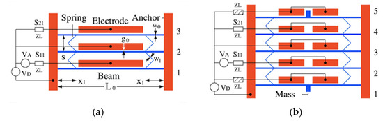
Figure 1.
Band-pass coupled-beam filters: (a) 3-beam system and (b) 5-beam system with compensating springs, mass-loaded end beams and split electrodes. Red—fixed parts; blue—movable parts.
Unfortunately, this arrangement does not provide dynamic synchronization. If each beam vibrates in isolation, with the others stationary, the end beams must have the elastic support of one pair of springs, while the central beam has that of two. Consequently, the effective resonant frequencies of beams 1 and 3 must differ from that of beam 2. One solution might be to connect an additional pair of springs from the end beams to anchors, restoring dynamic synchronization. However, application of the same DC voltage to each transducer cannot then cause equal beam motion since this would require deflection of the end springs alone. A common approach to such problems is to apply a different DC bias to each transducer [17,25]. However, the correction is extremely tedious.
2.2. FEM Simulation
The problem can be illustrated with FEM simulations of the device layout in Figure 1a, carried out using the commercial software COMSOL® [58]. Three coupled modules (Solid Mechanics, Electrostatics and Electrical Circuit) were used. First, the mechanical layout and constraints were set up, and elastic and inertial constants were defined. Inertial damping was estimated from the -factor. Electrostatic drives were defined on opposing surfaces of cuboid air volumes between each beam and a fixed electrode. Terminals were added to allow application of DC and AC voltages, with the AC input and output being connected via load resistors . The mechanism and air gaps were meshed using a free triangular mesh, using different mesh sizes to reduce simulation time. A frequency sweep was used to calculate S-parameter variations from terminal currents.
The following values were assumed for dimensions: , , , , , , and . A density of , Young’s moduli of and and a Poisson’s ratio of were chosen to model devices in (100) Si with the micro- and nano-structured beams in the <110> and <010> directions [59]. A quality factor of was taken as representative; however, its value is of limited significance provided it is large. An AC voltage of was used for dynamic actuation.
DC voltages and were first applied to the end and central beams to achieve tuning at a design frequency of , as and , below the snap-down voltage of . The impedance was then adjusted to achieve matching, as . Figure 2a shows the resulting variation of the S-parameters with frequency. Apart from the high value of (a known feature of coupled beam devices [21,47]), high performance is obtained; the response is bandpass, with correct tuning and broadband matching. However, determination of the DC voltages is a laborious process, which must be repeated each time parameters change. For example, Figure 2b shows the extracted variation of with the width of the linking springs, likely to vary in production. The ratio is not constant, implying that both voltages must be continually rediscovered. Similar effects occur if the electrode gap is altered, and even minor departure from suitable voltages leads to an unrecognisable response or failed simulation.
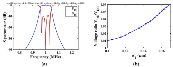
Figure 2.
(a) Frequency response of 3-beam filter with purely electrostatic tuning, as predicted by the FEM; (b) extracted variation of voltage ratio with linking spring width .
2.3. Dynamic Synchronization
Here we propose the solution shown in Figure 1b, which allows a single DC voltage. The array is now equipped with an additional beam at either end, coupled to its neighbour by springs and equipped with transducers to which DC voltages are applied. As in Figure 1a, a common DC voltage will yield equal deflections of all 5 beams. The additional beams are mass-loaded at their midpoint. Ideally, this mass will be formed by a variation in layout. However, care will be required to locate it in the available space without modifying beam stiffness. One possibility, shown here, is to place both masses outside the array, splitting the upper electrode to clear the mass (and splitting the remainder to retain synchronization). If the masses are large enough, the resonances of beams 1 and 5 will differ sufficiently from that of beams 2–4 that they take no part in the in-band response. Thus, the array may be considered as five statically synchronized beams for DC bias, and three dynamically synchronized beams for AC signals.
3. Lumped Element Model
In this section we construct a lumped element model of a set of coupled resonant beams with parallel-plate drives and show how mass-loading can control the response.
3.1. Resonant Modes of a Vibrating Beam
We start by considering the resonant modes of an undamped, undriven beam of length , width and depth , formed in a material of density and Young’s modulus . These are the solutions to the dynamic Euler beam-bending equation for a clamped-clamped beam, namely [60]:
Here is transverse displacement, and is position along the beam. The eigenvalues are related to the angular resonant frequencies by , where is the area and /12 is the second moment of area, and satisfy the characteristic equation . This equation has a set of discrete solutions. Here we are concerned with the lowest-order mode, which corresponds to . The term is a normalization constant, chosen so that . More generally, the beam may have a distributed damping per unit length and be driven by a force per unit length.
3.2. Lumped Element Model
Figure 3a shows the lumped element model, in which each resonator except the first and the last is considered as a mass supported on a spring of stiffness . Again, the red and blue features show fixed and moving parts, and damping is omitted for clarity.
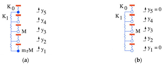
Figure 3.
Lumped models of Figure 1b, with (a) mass loaded and (b) fixed end elements.
Equivalence with the distributed model is established using the factors and which have the values 0.5232 and 0.3965, respectively. These allow the lumped mass , stiffness , damping coefficient and force to be found as [21]:
For the outer elements, the mass is increased to , where is a mass ratio and is an additional lumped-element mass. The coupling springs are formed from elements of length , width , depth , density and Young’s modulus , inclined at 45° angles to give a separation between the beams. The equivalent spring constant and mass of each pair are and , where and . Here a different elastic modulus is introduced as before, and the mass is half the actual mass, to model the motion of the centre of mass of each spring. Perturbation theory then allows an equivalent lumped element coupling stiffness to be found as:
For very small springs, the effect of the mass may often be ignored. Development of a model for electrostatic transducers is more complicated. Following [21] we assume that the electrodes act as parallel plate capacitors with capacitance:
Here is the initial gap and is a static displacement. Application of a DC voltage generates a static force:
Here is the derivative of . Static equilibrium then implies that . Here is the effective stiffness, which may reasonably be approximated as . This is a standard snap-down problem, leading to the cubic equation:
Here is the normalised deflection and . Solution allows calculation of , and the second derivative . When an additional AC voltage is applied from a source with output impedance , the result is an AC force , a reduction in stiffness and an effective load given by:
In general, the characteristic impedance of a coupled beam array is complex, but for an infinite lossless array at resonance it has the real value:
Here is the effective angular resonant frequency. Matching can then be achieved by choosing . This requires the load resistance to be chosen so that . However, large values of are needed if is small [21].
3.3. Coupled Equations
Combining the results above it is simple to show that the governing equations for a 5-element array with input and output ports at and subject to a harmonic drive at angular frequency are:
These equations can be solved by inversion of the equivalent matrix representation, and reflection and transmission scattering parameters can then be found using standard methods. Here, however, we focus on the resonant modes.
3.4. Resonant Modes
In the absence of damping, loading and a driving force, Equation (9) reduce to:
Introducing the terms , , and , these equations may be re-written as:
For characteristic modes oscillating at the angular resonance frequency , we may write , where the constants define the overall mode shapes. The values are the eigenvalues of the tridiagonal matrix:
When is sufficiently different from , experience suggests that there will be little interaction between the outer masses and the remainder of the array. The eigenmodes will then separate into two groups. The first are the eigenvectors of the Toeplitz matrix , given by:
This matrix represents the dynamics of a reduced set of fully synchronized coupled resonators. Its eigenvalues are well-known, and lead to resonant frequencies:
Here . The corresponding eigenvectors have the form:
Here , and . The second set contains symmetric and anti-symmetric modes that predominantly involve oscillation of the outer masses at . These responses may be damped using similar loads to the matched loads at the ports.
To confirm these arguments, the blue lines in Figure 4a shows the variation with of the exact resonant frequencies, for an array with example parameters . The red lines show the approximate resonant frequencies. As rises, the exact solutions tend to the approximations, and resonances predominantly involving the outer masses separate from the remainder. Figure 4b shows the mode amplitudes for and . The blue traces show the first set of modes while the red traces show the second. As predicted, the former is approximated by Equation (15), while the latter mainly involve the outer masses. Provided only the first modes are excited, the array behaves as if the outer masses are stationary, as shown in Figure 3b.
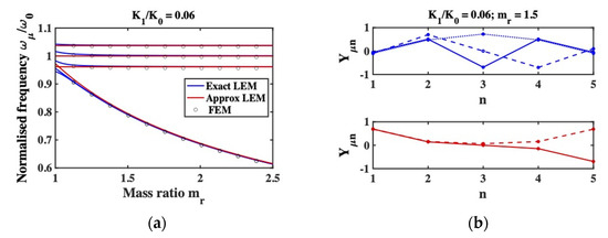
Figure 4.
(a) Variation of exact and approximate resonant frequencies of a 5-beam system with mass ratio , as predicted by the LEM for . Points show predictions of a comparable FEM; (b) Exact mode shapes of a 5-beam system predominantly involving the inner (blue) and outer (red) beams, as predicted by the LEM for and .
For comparison, the discrete points in Figure 4a show the predictions of the FEM for a 5-beam system with the same dimensional parameters as those used for Figure 2, which yields an equivalent value of . A rectangular mass is added to beams 1 and 5, and the mass ratio is calculated as described above. The points follow the continuous traces almost exactly. Similarly, Figure 5 shows the shapes of the highest eigenmodes predicted by the FEM for ; the outer beams are almost stationary as expected.
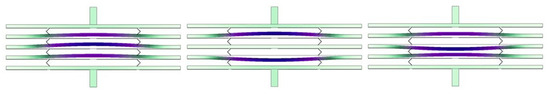
Figure 5.
Exact mode shapes of a 5-beam system with motion predominantly involving the inner beams, as predicted by the FEM.
4. Stiffness Matrix Model
In this section, we verify the previous arguments using the stiffness matrix method, which models beam networks by combining Euler beam bending theory with compatibility conditions [54,55]. The SMM is often preferred to FEM because of its increased speed. The high aspect ratio of most MEMS suspensions validates the use of Euler theory, and transducers may be modelled approximately as previously described [56,57].
4.1. Stiffness Matrix Model
Calculations were performed using a 2D SMM solver written in Matlab® [61]. The stiffness matrix was constructed from dimensions and material parameters, with reduced to model electrostatic detuning. Long beams were subdivided to ensure accuracy of resonant frequencies. Axial, transverse and angular displacements at each node were found for a vector of applied forces and torques (here a point load on the actuated beam).
Dynamic analysis was performed using additional mass and damping matrices. The mass matrix was formed by combining dimensions and densities with standard relations for motions of centres of mass. The damping matrix was modelled using Rayleigh’s method as [60]. Here and are mass and spring damping coefficients, with determined from the -factor and . Ports were simulated by increasing the damping for these beams, using a damping coefficient determined from the load impedance . Assuming harmonic forces and displacements as , substitution into the governing equation yields . This equation was solved by inversion, and the velocity vector constructed as . The scattering parameters and were then extracted from midpoint velocities.
4.2. Static Deflections
Responses were simulated for the same dimensional and material parameters as before. The single DC voltage and the impedances were adjusted to achieve tuning and matching at a design frequency of , as and , respectively. An AC voltage of was again used for dynamic actuation. Figure 6a shows the magnified static deflection for a 3-beam system with end springs but no additional end beams, confirming that this design yields unequal deflection and hence unequal electrostatic tuning. Figure 6b shows the deflection for a 5-beam system equivalent to Figure 1b; the modified suspension clearly equalizes the deflection as required.
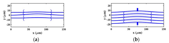
Figure 6.
Deflection of coupled-beam systems with a DC bias applied, as predicted by the SMM: (a) 3-beam system with end-springs; (b) 5-beam system without end springs.
4.3. Frequency Responses
Figure 7a shows the frequency variation of S-parameters for a 5-beam system with no added mass. As expected, the response is heavily distorted, with poor matching and a deep notch caused by the collective oscillation of an improperly synchronized system. Figure 7b shows the corresponding response when the first and fifth elements are loaded using masses with example width and length , yielding a mass ratio . Near the design frequency, the response is bandpass, with good matching and a flat passband. Additional unwanted transmission near 0.79 MHz can be attributed to excitation of the two low-frequency resonances in Figure 4.
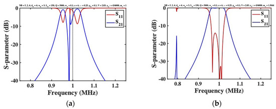
Figure 7.
Frequency response of a 5-beam filter with electrostatic detuning (a) with and (b) without added mass, as predicted by the SMM.
The unwanted response can be placed further out-of-band by increasing ; at the same time, passband flatness is improved. However, is limited by layout constraints. The dimensions of the mass may be reduced using material with density larger than silicon (for example, gold, with ), but only at price of fabrication complexity. A simpler solution is to damp the unwanted response, by connecting loads in series with the DC bias for the first and last beams. Figure 8a shows the response obtained using loads identical to those used for matching. The unwanted resonances are suppressed, leaving the desired bandpass response unaltered and confirming the design strategy.
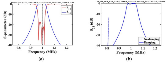
Figure 8.
Frequency response of an electrostatically tuned 5-beam filter with added mass and additional damping of the end beams, as predicted by (a) the SMM, and (b) the FEM.
All the results presented here were compared with the predictions of the LEM, and excellent agreement was obtained in each case. The responses shown in Figure 7b and Figure 8a were also reproduced using the FEM. Figure 8b shows the frequency dependence of for a 5-beam system with mass-loaded end beams, obtained using COMSOL with and without end-beam damping. Apart from a minor difference in the tuning voltage (attributed to approximation of the transducer in the SMM), and minor passband ripple (which reduces with or ), the results are as expected. A bandpass response is obtained, and end-beam resonances are effectively suppressed by damping.
5. Conclusions
A method to compensate for the electrostatic desynchronization of coupled beam arrays has been proposed and confirmed by simulation, with excellent agreement being obtained using lumped element, stiffness matrix and finite element models. Additional beams are simply added at either end of the array, together with the coupling elements needed to ensure equal displacement of all beams under a DC tuning voltage. If the additional beams are mass-loaded, they take no part in the collective in-band response. The remainder of the array then exhibits properly synchronized behavior, and any out-of-band resonance may be suppressed using external loading. Since the additional mass need only place the unwanted resonances somewhere out-of-band, this arrangement is extremely tolerant to the exact mass value. The passband may then be adjusted in frequency with a single DC voltage, simplifying compensation for fabrication-induced variation of key nanoscale dimensions such as the width of the linking suspension or the electrode gap.
The combination of feature size and aspect ratio greatly complicates fabrication of any such device. To maximize the Q-factor, single crystal materials such as bonded silicon-on-insulator (BSOI) or silicon-on-glass wafers are preferred [8,11]. Mechanical parts may be formed by anisotropic plasma etching. However, advanced lithography such as the high-aspect-ratio combined poly and single crystal silicon (HARPSS) micromachining process would be needed to form sub-micron electrode gaps [43]. Sidewall transfer lithography (STL) has already been shown capable of integrating nanoscale suspensions with MEMS parts [45]. Electrical connection to fixed electrodes (many of which lie within the mechanical structure) also presents a challenge and is most easily achieved using buried or flip-chip bonded tracks.
The application presented here is to a three-beam filter. However, elimination of the need for multiple tuning voltages should simplify development of high-order filters based on larger beam arrays. Extension to four-port acoustic MEMS devices such as directional couplers and directional coupler filters (which allow more effective signal separation) is obvious, and we have already investigated example designs. Applicational to out-of-plane and torsional motion may also be possible. The principle is therefore general and may enable realization of a wide range of new filter devices.
Author Contributions
Conceptualization, R.S.; methodology, R.S.; software, R.S. and A.B.; validation, R.S. and A.B.; formal analysis, R.S.; investigation, A.B.; writing—original draft preparation, R.S.; writing—review and editing, A.B.; supervision, R.S. Both authors have read and agreed to the published version of the manuscript.
Funding
This research received no external funding.
Acknowledgments
A. Bouchaala is grateful to Imperial College London for a PhD studentship.
Conflicts of Interest
The authors declare no conflict of interest.
References
- Adler, R. Compact electromechanical filters. Electronics 1947, 20, 100–105. [Google Scholar] [CrossRef]
- Roberts, W.V.B.; Burns, L.L. Mechanical filters for radio frequencies. RCA Rev. 1949, 10, 348–365. [Google Scholar]
- Lundgren, D.L. Electromechanical filters for single sideband applications. Proc. IRE 1956, 44, 1744–1749. [Google Scholar] [CrossRef]
- Hathaway, J.C.; Babcock, D.F. Survey of mechanical filters and their applications. Proc. IRE 1957, 45, 5–16. [Google Scholar] [CrossRef]
- Johnson, R.A.; Börner, M.; Konno, M. Mechanical filters—A review of progress. IEEE Trans. Sonics Ultrason. 1971, SU-18, 155–170. [Google Scholar] [CrossRef]
- Sheahan, D.F.; Johnson, R.A. Crystal and mechanical filters. IEEE Trans. Circuits Syst. 1975, CAS-22, 69–89. [Google Scholar] [CrossRef]
- Nathanson, H.C.; Wickstrom, R.A. A resonant-gate silicon surface transistor with high-Q bandpass properties. Appl. Phys. Lett. 1965, 7, 84–86. [Google Scholar] [CrossRef]
- Roszhart, T.V. The effect of thermoelastic friction on the Q of micro-machined silicon resonators. In Proceedings of the Technical Digest IEEE Solid-State Sensor Actuator Workshop, Hilton Head, SC, USA, 4–7 June 1990; pp. 13–16. [Google Scholar] [CrossRef]
- Blom, F.R.; Bouwstra, S.; Elwenspoek, M.; Fluitman, J.H.J. Dependence of the quality factor of micromachined silicon beam resonators on pressure and geometry. J. Vac. Sci. Technol. B 1992, 10, 19–26. [Google Scholar] [CrossRef] [Green Version]
- Zhang, X.; Tang, W.C. Viscous air damping in laterally driven micro-resonators. In Proceedings of the IEEE MEMS Conference, Oiso, Japan, 25–28 January 1994; pp. 199–204. [Google Scholar] [CrossRef]
- Yang, J.; Ono, T.; Esashi, M. Energy dissipation in submicrometer thick single-crystal silicon cantilevers. J. Microelectromech. Syst. 2002, 11, 775–783. [Google Scholar] [CrossRef]
- Srikar, V.T.; Senturia, S.D. Thermoelastic damping in fine-grained polysilicon flexural beam resonators. J. Microelectromech. Syst. 2002, 11, 499–504. [Google Scholar] [CrossRef]
- Tang, W.C.; Nguyen, T.-C.H.; Howe, R.T. Laterally driven polysilicon resonant microstructures. Sens. Actuators 1989, 20, 25–32. [Google Scholar] [CrossRef]
- Tang, W.C.; Nguyen, C.T.-C.; Judy, M.W. Electrostatic-comb drive of lateral polysilicon resonators. Sens. Actuators A 1990, 21, 328–331. [Google Scholar] [CrossRef]
- Wang, K.; Bannon, F.D.; Clark, H.R.; Nguyen, C.T.-C. Q-enhancement of microelectromechanical filters via low velocity spring coupling. In Proceedings of the IEEE Ultrasonics Symposium, Toronto, ON, Canada, 5–8 October 1997; pp. 323–332. [Google Scholar] [CrossRef] [Green Version]
- Lin, L.; Howe, R.T.; Pisano, A.P. Micromechanical filters for signal processing. J. Microelectromech. Syst. 1998, 7, 286–294. [Google Scholar] [CrossRef]
- Wang, K.; Nguyen, C.T.-C. High-order medium frequency micromechanical electronic filters. J. Microelectromech. Syst. 1999, 8, 534–556. [Google Scholar] [CrossRef] [Green Version]
- Nguyen, C.T.-C. Micromechanical resonators for oscillators and filters. In Proceedings of the IEEE Ultrasonics Symposium, Seattle, WA, USA, 7–10 November 1995; pp. 489–499. [Google Scholar] [CrossRef]
- Bannon, F.D.; Clark, J.R.; Nguyen, C.T.-C. High frequency microelectromechanical IF filters. In Proceedings of the Technical Digest IEEE Electron Devices Meeting, San Francisco, CA, USA, 8–11 December 1996; pp. 773–776. [Google Scholar] [CrossRef] [Green Version]
- Clark, J.R.; Bannon, F.D.; Wong, A.-C.; Nguyen, C.T.-C. Parallel-resonator HF micromechanical bandpass filters. In Proceedings of the Transducers Conference, Chicago, IL, USA, 16–19 June 1997; pp. 1161–1164. [Google Scholar] [CrossRef]
- Bannon, F.D.; Clark, J.R.; Nguyen, C.T.-C. High-Q HF microelectromechanical filters. IEEE J. Solid-State Circuits 2000, 35, 512–526. [Google Scholar] [CrossRef] [Green Version]
- Wang, K.; Wong, A.-C.; Nguyen, C.T.-C. VHF free-free beam high-Q micromechanical resonators. J. Microelectromech. Syst. 2000, 9, 347–360. [Google Scholar] [CrossRef] [Green Version]
- Li, S.-S.; Demirci, M.U.; Lin, Y.-W.; Rec, Z.; Nguyen, C.T.-C. Bridged micromechanical filters. In Proceedings of the IEEE Frequency Control Symposium and Exposition, Montreal, QC, Canada, 23–27 August 2004; pp. 144–150. [Google Scholar] [CrossRef]
- Li, M.-H.; Chen, W.-C.; Li, S.S. Mechanically coupled CMOS-MEMS free-free beam resonator arrays with enhanced power handling capability. IEEE Trans. Ultrason. Ferroelectr. Freq. Control 2012, 59, 346–356. [Google Scholar] [CrossRef] [PubMed]
- Naghsh Nilchi, J.; Liu, R.; Nguyen, C.T.-C. 7th order sharp-roll-off bridged micromechanical filter. In Proceedings of the Transducers Conference, Anchorage, AK, USA, 21–25 June 2015; pp. 137–140. [Google Scholar] [CrossRef]
- Galayko, D.; Kaiser, A.; Legrand, B.; Buchaillot, L.; Combi, C.; Collard, D. Coupled resonator micromechanical filters with voltage tunable bandpass characteristic in thick-film polysilicon technology. Sens. Actuators A 2006, 126, 227–240. [Google Scholar] [CrossRef]
- Hajhashemi, M.S.; Amini, A.; Bahreyni, B. A micromechanical bandpass filter with adjustable bandwidth and bidirectional control of centre frequency. Sens. Actuators A 2012, 187, 10–15. [Google Scholar] [CrossRef]
- Manav, M.; Reynen, G.; Sharma, M.; Cretu, E.; Phani, A.S. Ultrasensitive resonant MEMS transducers with tuneable coupling. J. Micromech. Microeng. 2014, 24, 055005. [Google Scholar] [CrossRef]
- Zhang, W.-M.; Hu, K.-M.; Peng, Z.-K.; Meng, G. Tunable micro- and nanomechanical resonators. Sensors 2015, 15, 26478–26566. [Google Scholar] [CrossRef] [Green Version]
- Al Hafiz, M.A.; Kosuru, L.; Hajjaj, Z.Z.; Younis, M.I. Highly tunable narrow bandpass MEMS filter. IEEE Trans. Electron Dev. 2017, 64, 3392–3398. [Google Scholar] [CrossRef]
- Galayko, D.; Kaiser, A.; Buchaillot, L.; Collard, D.; Combi, C. Microelectromechanical variable-bandwidth IF frequency filters with tunable electrostatic coupling spring. In Proceedings of the IEEE MEMS Conference, Kyoto, Japan, 19–23 January 2003; pp. 153–156. [Google Scholar] [CrossRef]
- Pourkamali, S.; Abdolvand, R.; Ayazi, F. A 600 kHz electrically-coupled MEMS bandpass filter. In Proceedings of the IEEE MEMS Conference, Kyoto, Japan, 19–23 January 2003; pp. 702–705. [Google Scholar] [CrossRef]
- Pourkamali, S.; Ayazi, F. Electrically-coupled MEMS bandpass filters: Part I. With coupling element. Sens. Actuators A 2005, 122, 307–316. [Google Scholar] [CrossRef] [Green Version]
- Pourkamali, S.; Ayazi, F. Electrically-coupled MEMS bandpass filters: Part II. Without coupling element. Sens. Actuators A 2005, 122, 317–325. [Google Scholar] [CrossRef] [Green Version]
- Verbiest, G.J.; Xu, D.; Goldsche, M.; Khodkov, T.; Barzanjeh, S.; von den Driesch, N.; Buca, D.; Stampfer, C. Tunable mechanical coupling between driven microelectromechanical resonators. Appl. Phys. Lett. 2016, 109, 143507. [Google Scholar] [CrossRef] [Green Version]
- Greywall, D.S.; Busch, P.A. Coupled micromechanical drumhead resonators with practical application as electromechanical bandpass filters. J. Micromech. Microeng. 2002, 12, 925–938. [Google Scholar] [CrossRef]
- Demirci, M.U.; Nguyen, C.T.C. Mechanically corner-coupled square microresonator array for reduced series motional resistance. J. Microelectromech. Syst. 2006, 15, 1419–1435. [Google Scholar] [CrossRef] [Green Version]
- Clark, J.R.; Pai, M.; Wissman, B.; He, G.; Hsu, W.-T. Parallel-coupled square-resonator micromechanical filter arrays. In Proceedings of the IEEE Int. Frequency Control Symposium and Exposition, Miami, FL, USA, 4–7 June 2006; pp. 485–490. [Google Scholar] [CrossRef]
- Chivukula, V.B.; Rhoads, J.F. Microelectromechanical bandpass filters based on cyclic coupling architectures. J. Sound Vibr. 2010, 329, 4313–4332. [Google Scholar] [CrossRef]
- Pachkawade, V.; Junghare, R.; Patrikar, R.; Kraft, M. Mechanically coupled ring-resonator filter and array (analytical and finite element model). IET Comput. Digit. Tech. 2016, 10, 261–267. [Google Scholar] [CrossRef] [Green Version]
- Chou, C.-Y.; Li, M.-H.; Chen, C.-Y.; Liu, C.-Y.; Li, S.-S. An innovative 3-D mechanically-coupled array design for MEMS resonator and oscillators. In Proceedings of the Transducers Conference, Kaohsiung, Taiwan, 18–22 June 2017; pp. 90–93. [Google Scholar] [CrossRef]
- Bouchaala, A.; Syms, R.R.A. New architectures for micromechanical coupled beam array filters. Microsyst. Technol. 2020, 27, 3377–3387. [Google Scholar] [CrossRef]
- Abdolvand, R.; Ho, G.K.; Ayazi, F. Poly-wire-coupled single crystal HARPSS micromechanical filters using oxide islands. In Proceedings of the Solid State Sensor, Actuator and Microsystems Workshop, Hilton Head, SC, USA, 6–10 June 2004; pp. 242–245. [Google Scholar]
- Arellano, N.; Quévy, E.P.; Provine, J.; Maboudian, R.; Howe, E.T. Silicon nanowire coupled micro-resonators. In Proceedings of the IEEE MEMS Conference, Tuczon, AZ, USA, 13–17 January 2008; pp. 721–724. [Google Scholar] [CrossRef]
- Liu, D.; Syms, R.R.A. NEMS by sidewall transfer lithography. IEEE J. Microelectromech. Syst. 2014, 23, 1366–1373. [Google Scholar] [CrossRef]
- Tasdemir, Z.; Wollschläger, N.; Österle, W.; Leblbici, Y.; Alaca, B.E. A deep etching mechanism for trench-bridging silicon nanowires. Nanotechnology 2016, 27, 095303. [Google Scholar] [CrossRef]
- Pourkamali, S.; Hashimura, A.; Abdolvand, R.; Ho, G.K.; Erbil, A.; Ayazi, F. High-Q single crystal silicon HARPSS capacitive beam resonators with self- aligned sub-100-nm transduction gaps. J. Microelectromech. Syst. 2003, 12, 487–496. [Google Scholar] [CrossRef] [Green Version]
- Kim, H.C.; Chun, K. Photo-assisted electrochemical etching of nano-gap trench with high aspect ratio for MEMS applications. J. Micromech. Microeng. 2006, 16, 906–913. [Google Scholar] [CrossRef]
- Mukakami, S.; Konno, M.; Ikehara, T.; Maeda, R.; Mihara, T. Fabrication of 150-nm-wide transducer gaps for disc-type resonators by single dry etching process. Jpn. J. Appl. Phys. 2010, 49, 06GN04. [Google Scholar] [CrossRef]
- Van Toan, N.G.; Toda, M.; Kawai, Y.; Ono, T. A capacitive silicon resonator with a movable electrode structure for gap width reduction. J. Micromech. Microeng. 2014, 24, 025006. [Google Scholar] [CrossRef]
- Zienkiewicz, O.C.; Taylor, R.L.; Zhu, J.Z. The Finite Element Method: Its Basis and Fundamentals; Butterworth Heinemann: Oxford, UK, 2013. [Google Scholar] [CrossRef]
- Senturia, S.D.; Harris, R.M.; Johnson, B.P.; Kim, S.; Nabors, K.; Shulman, M.A.; White, J.K. A computer-aided design system for microelectromechanical systems (MEMCAD). J. Microelectromech. Syst. 1992, 1, 3–13. [Google Scholar] [CrossRef]
- Gilbert, J.R.; Legtenberg, R.; Senturia, S.D. 3D coupled electro-mechanics: Applications of Co-Solve EM. In Proceedings of the IEEE MEMS Conference, Amsterdam, The Netherlands, 29 January–2 February 1995; pp. 122–127. [Google Scholar] [CrossRef] [Green Version]
- Livesey, R.K. Matrix Methods of Structural Analysis; Pergamon: Oxford, UK, 1964. [Google Scholar] [CrossRef]
- McGuire, W.; Gallagher, R.H.; Ziemian, R.D. Matrix Structural Analysis, 2nd ed.; John Wiley: New York, NY, USA, 2000. [Google Scholar] [CrossRef]
- Clark, J.V.; Zhou, N.; Pister, K.S.J. MEMS Simulation Using SUGAR v0.5. In Proceedings of the Solid-State Sensor and Actuator Workshop, Hilton Head, SC, USA, 8–11 June 1998; pp. 191–196. [Google Scholar]
- Clark, J.V.; Zhou, N.; Bindel, D.; Schenato, L.; Wu, W.; Demmel, J.; Pister, K.S.J. 3D MEMS simulation modeling using modified nodal analysis. In Proceedings of the Microscale Systems: Mechanics and Measurements Symposium, Orlando, FL, USA, 8 June 2000; pp. 68–75. [Google Scholar]
- Available online: https://uk.comsol.com (accessed on 6 September 2021).
- Hopcroft, M.A.; Nix, W.D.; Kenny, T.W. What is the Young’s modulus of silicon? J. Microelectromech. Syst. 2010, 19, 229–238. [Google Scholar] [CrossRef] [Green Version]
- Thomson, W.T. Theory of Vibration with Applications, 4th ed.; Prentice Hall: Englewood Cliffs, NJ, USA, 1993. [Google Scholar] [CrossRef]
- Available online: https://www.mathworks.com/products/matlab.html (accessed on 6 September 2021).
Publisher’s Note: MDPI stays neutral with regard to jurisdictional claims in published maps and institutional affiliations. |
© 2021 by the authors. Licensee MDPI, Basel, Switzerland. This article is an open access article distributed under the terms and conditions of the Creative Commons Attribution (CC BY) license (https://creativecommons.org/licenses/by/4.0/).