Carbon Nanomaterials as Versatile Platforms for Biosensing Applications


Abstract
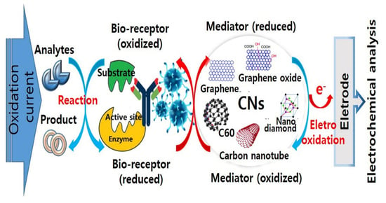
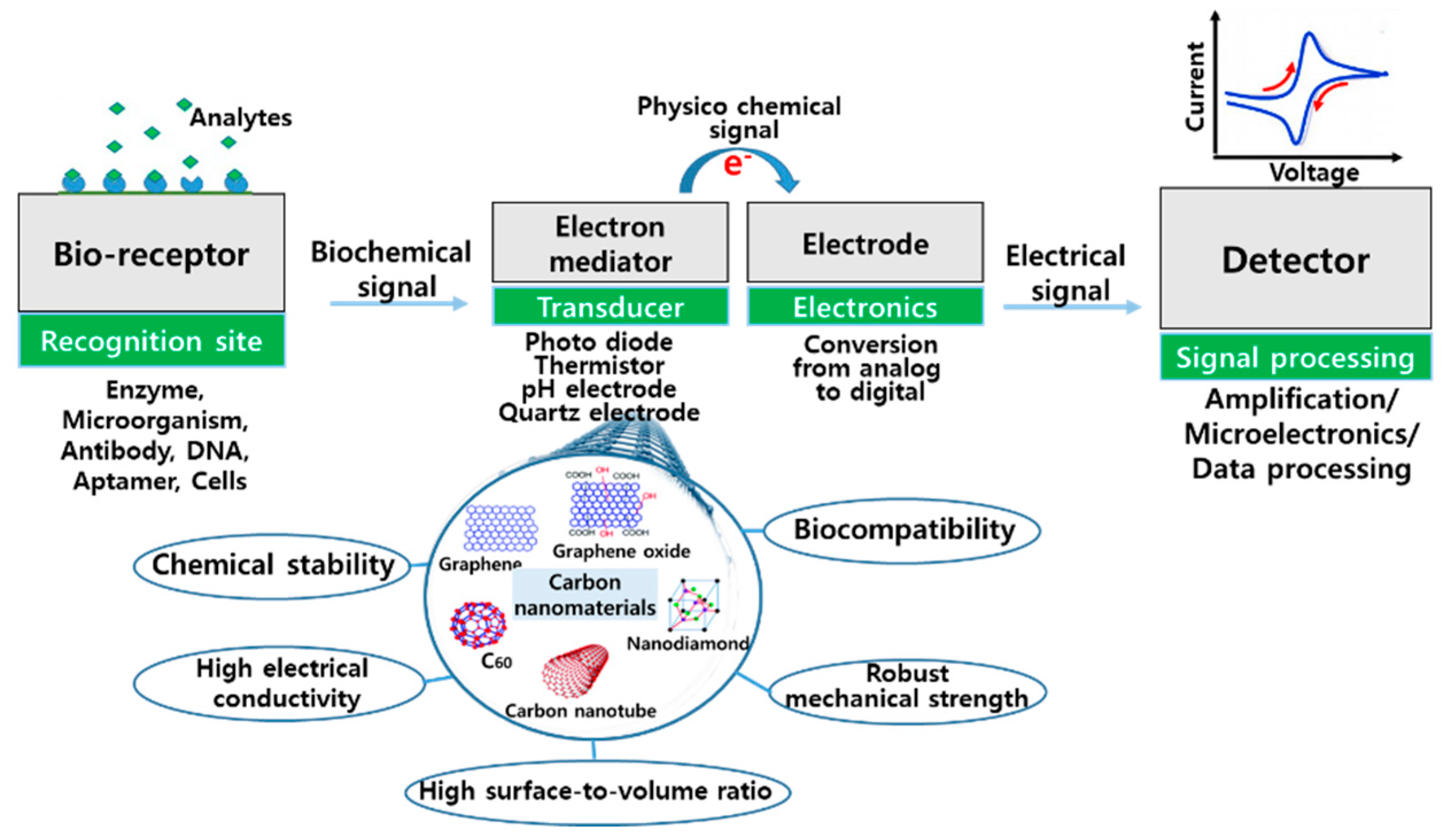
1. Introduction
2. Carbon Nanotubes (CNTs)
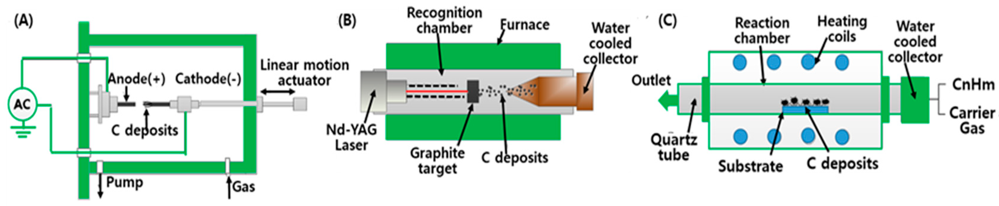
2.1. CNT Synthesis
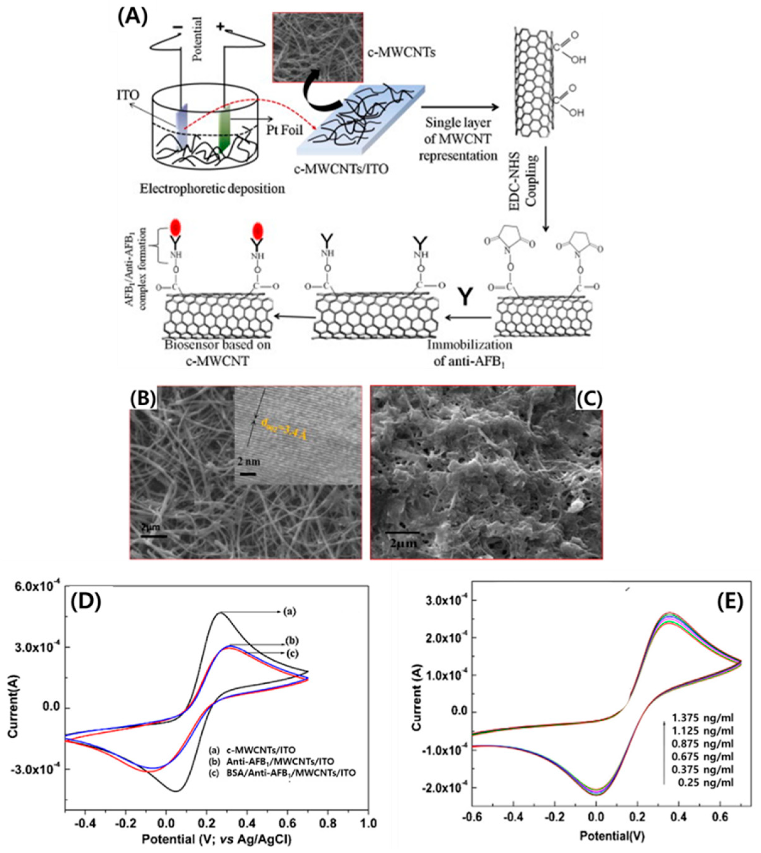
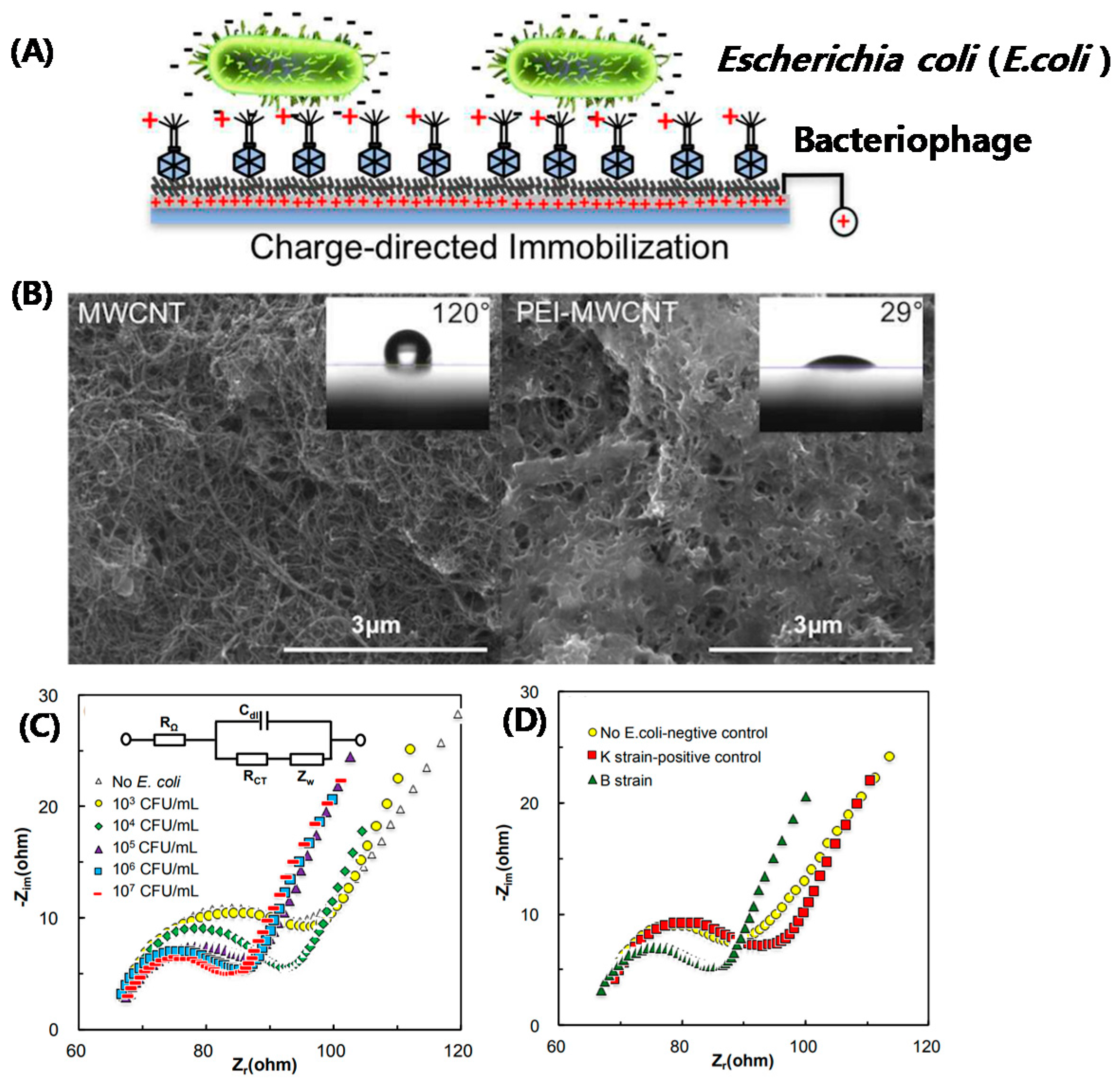
2.2. Electrochemical and Electronic CNT Biosensors
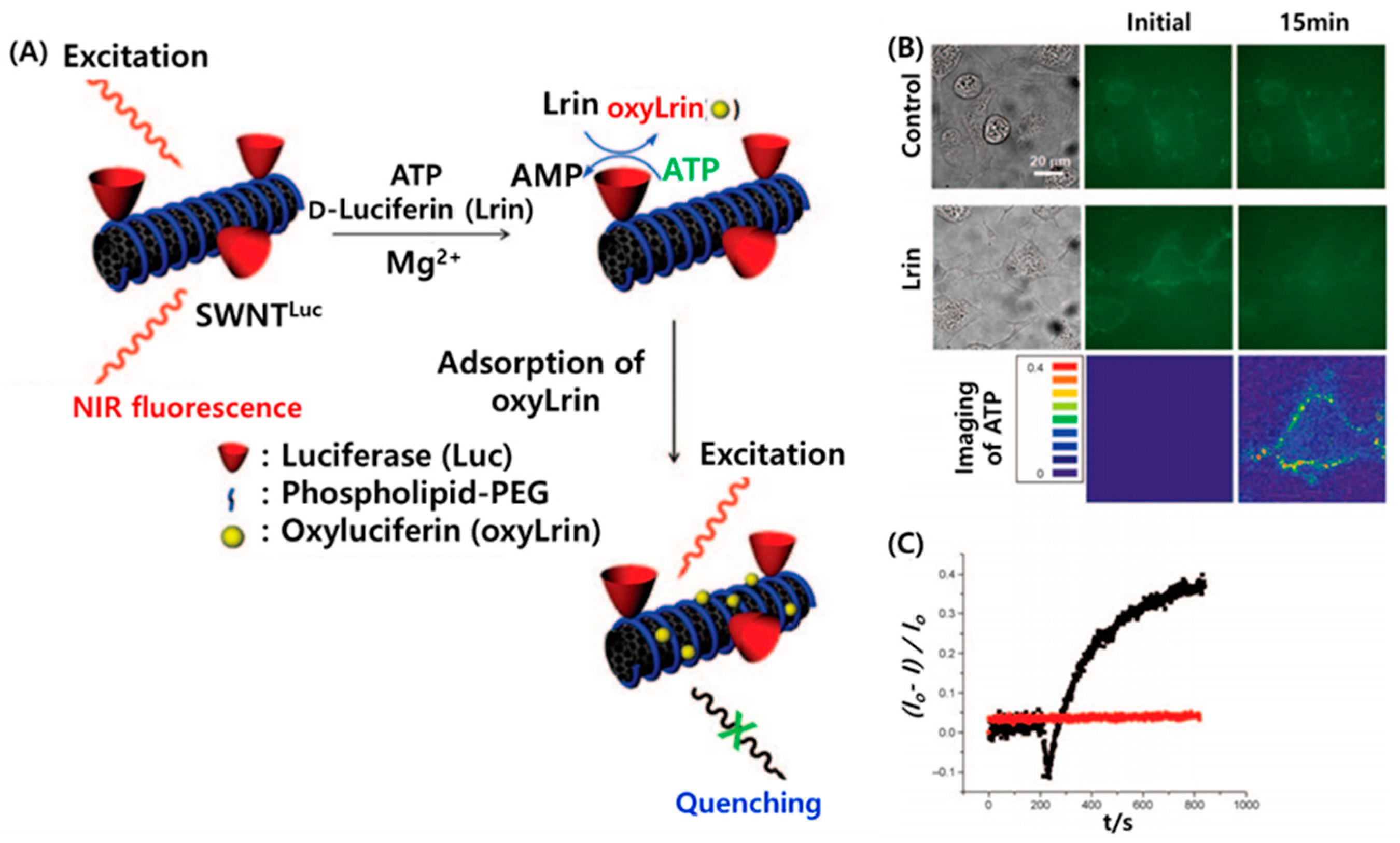
2.3. Optical CNT Biosensors
3. Carbon Nanodiamonds (NDs)
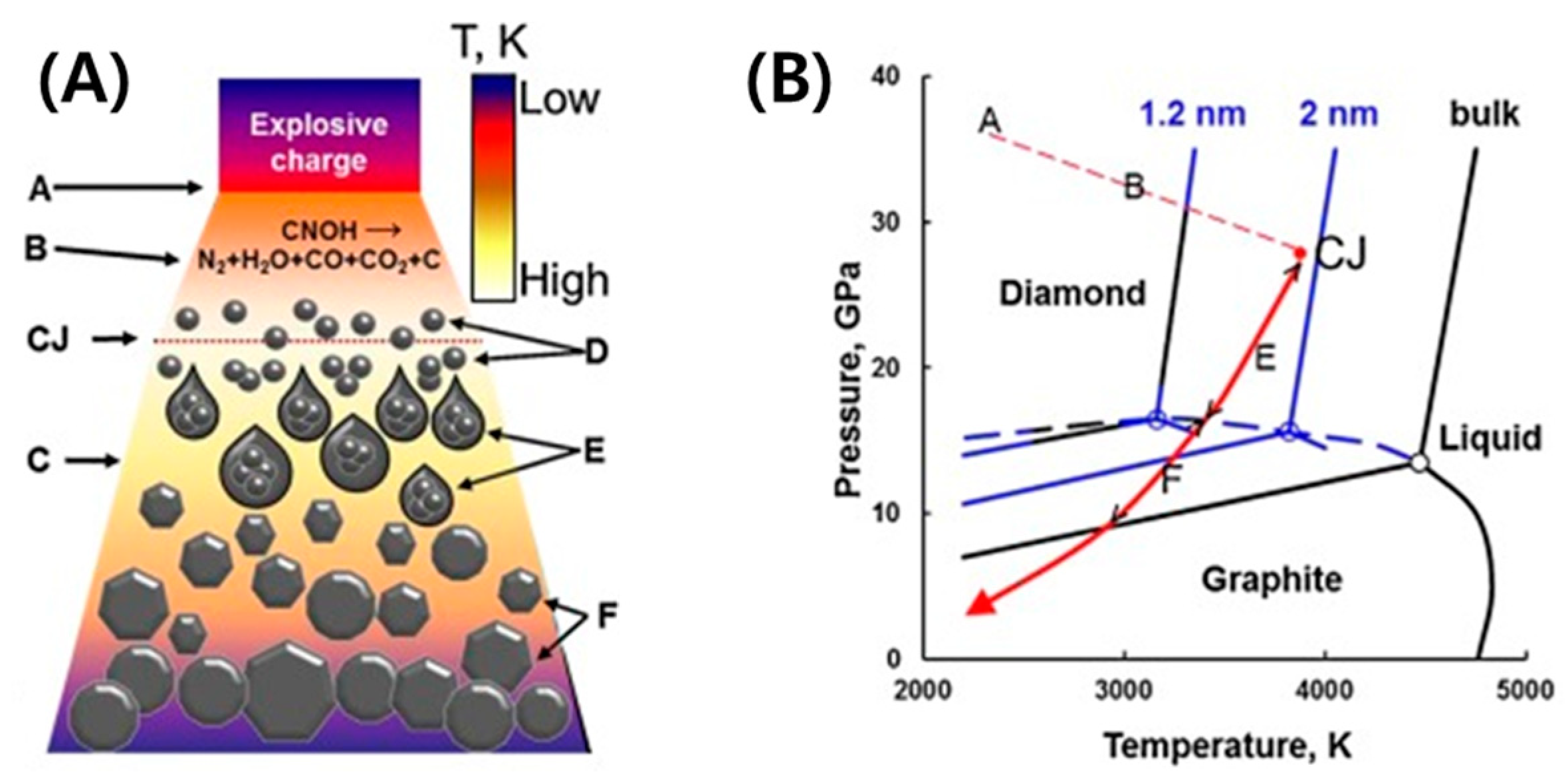
3.1. Synthesis and Purification
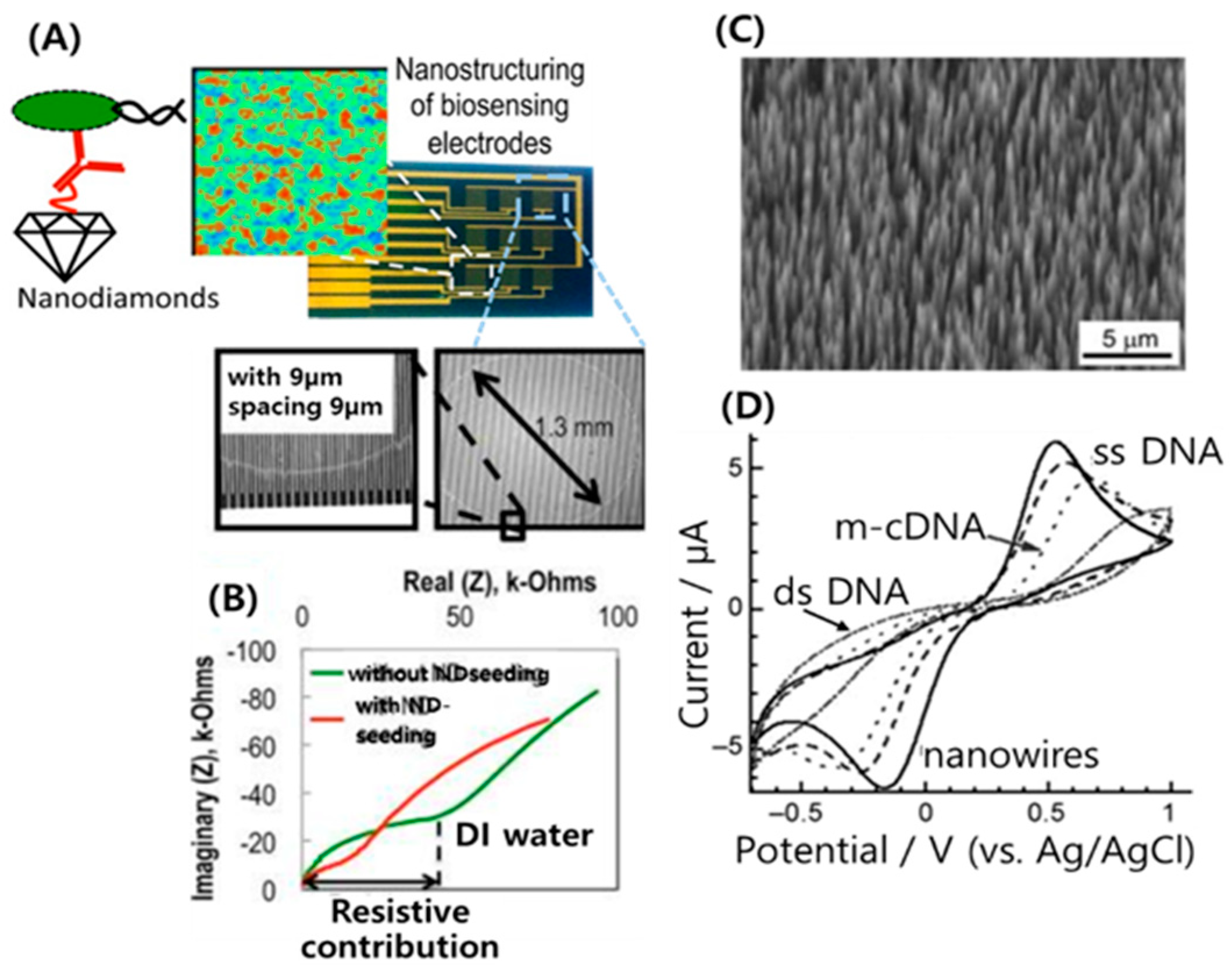
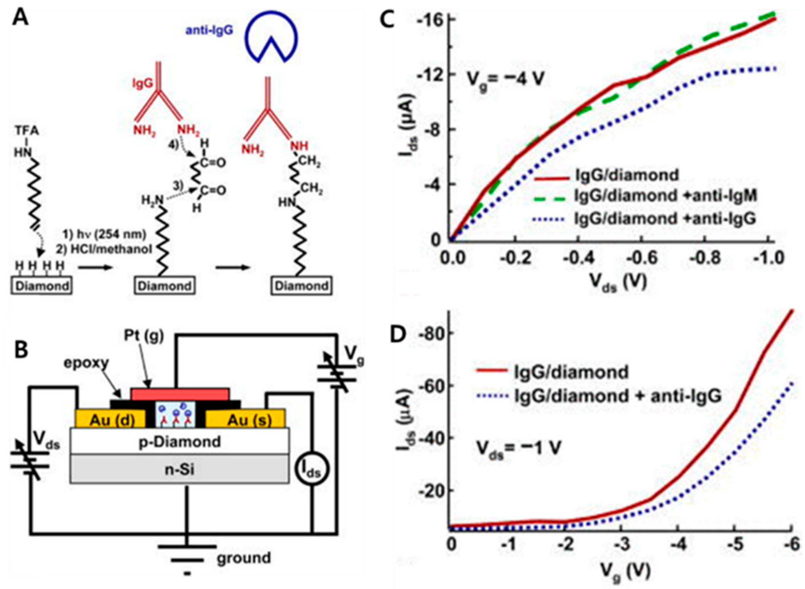
3.2. Nanodiamonds for Biosensing Applications
4. Graphene (GR) for Electrochemical Biosensors
4.1. Graphene Synthesis
4.1.1. Exfoliation
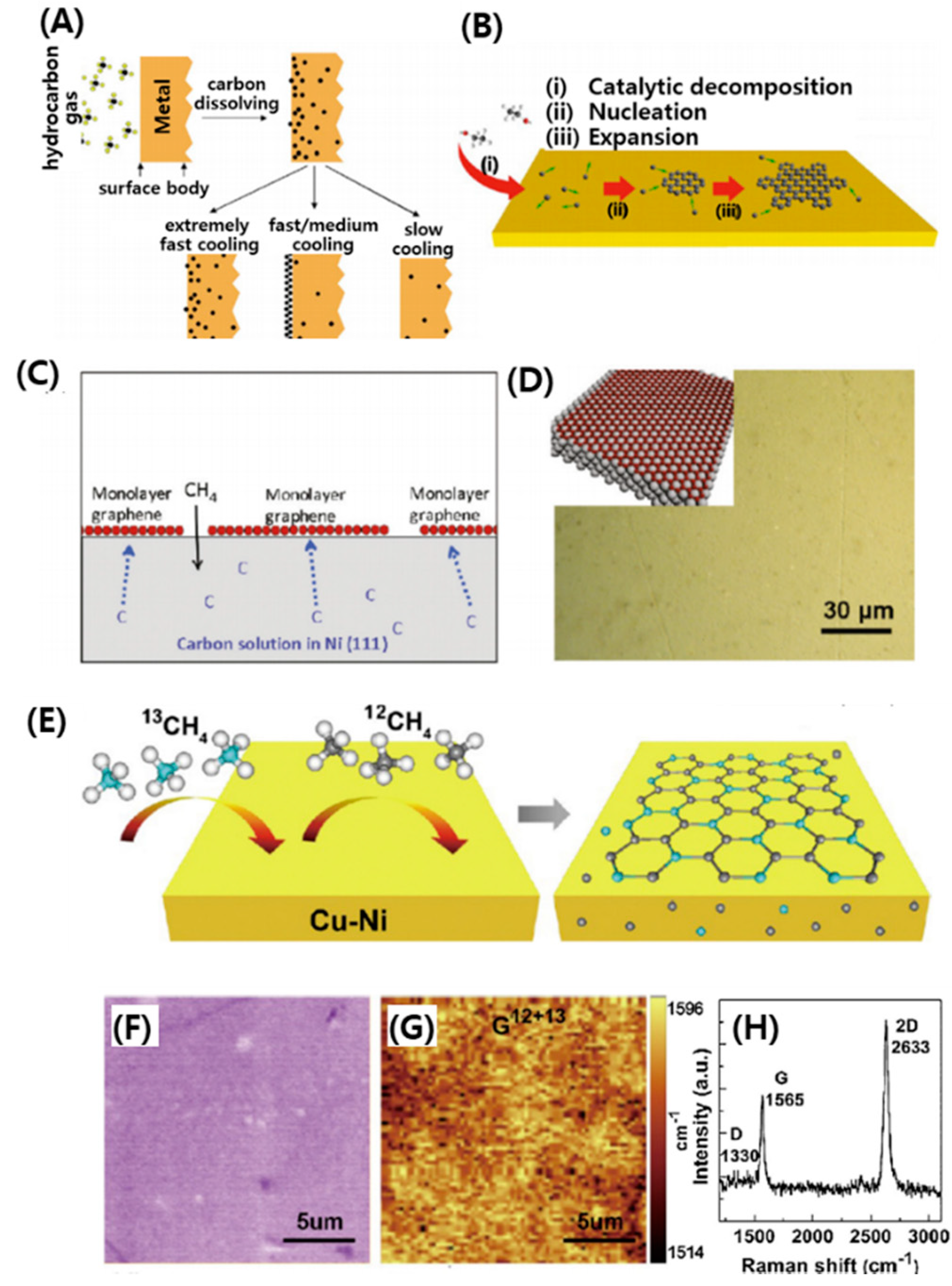
4.1.2. Thermal Chemical Vapor Deposition (CVD) Techniques
4.1.3. Plasma Enhanced Chemical Vapor Deposition (PECVD) Techniques
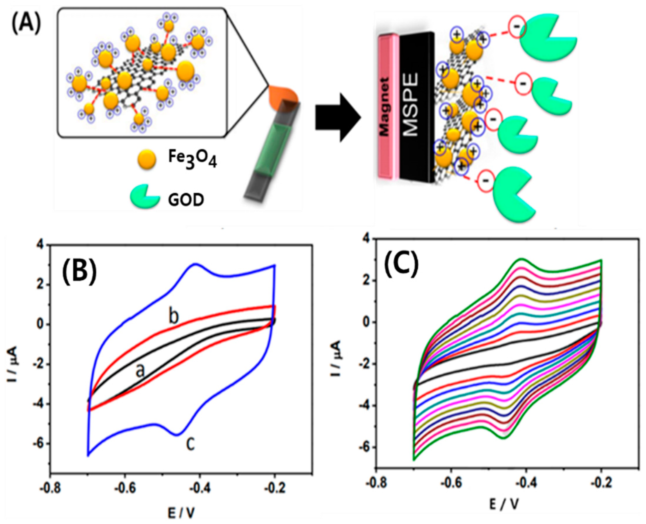
4.2. Enzymatic Glucose Biosensor Based on Graphene
4.3. Non-Enzymatic Glucose Graphene-Based Biosensor
5. Fullerenes for Electrochemical Biosensors
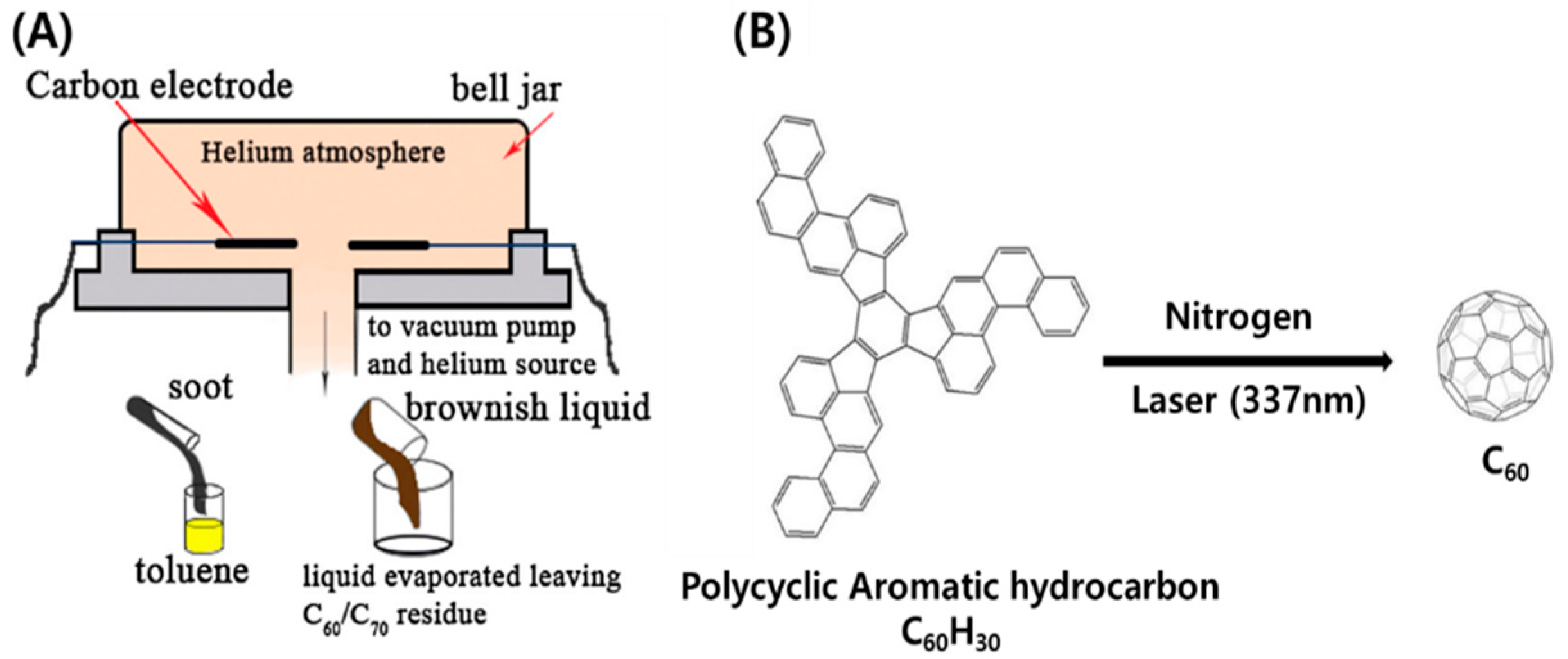
5.1. Synthesis of Fullerenes
5.2. Fullerenes in Enzymatic Biosensing
5.3. Fullerenes in Affinity Biosensing
6. Conclusions
Author Contributions
Funding
Conflicts of Interest
References
- Wang, Z.; Dai, Z. Carbon nanomaterial-based electrochemical biosensors: An overview. Nanoscale 2015, 7, 6420–6431. [Google Scholar] [CrossRef] [PubMed]
- Kour, R.; Arya, S.; Young, S.J.; Gupta, V.; Bandhoria, P.; Khosla, A. Review-Recent Advances in Carbon Nanomaterials as Electrochemical Biosensors. J. Electrochem. Soc. 2020, 167, 037555. [Google Scholar] [CrossRef]
- Holzinger, M.; Le Goff, A.; Cosnier, S. Nanomaterials for biosensing applications: A review. Front. Chem. 2014, 2, 63. [Google Scholar] [CrossRef] [PubMed]
- Biju, V. Chemical modifications and bioconjugate reactions of nanomaterials for sensing, imaging, drug delivery and therapy. Chem. Soc. Rev. 2014, 43, 744–764. [Google Scholar] [CrossRef] [PubMed]
- Keerthi, M.; Akilarasan, M.; Chen, S.M.; Kogularasu, S.; Govindasamy, M.; Mani, V.; Ali, M.A.; Al-Hemaid, F.M.A.; Elshikh, M.S. One-Pot Biosynthesis of Reduced Graphene Oxide/Prussian Blue Microcubes Composite and Its Sensitive Detection of Prophylactic Drug Dimetridazole. J. Electrochem. Soc. 2018, 165, B27–B33. [Google Scholar] [CrossRef]
- Muthumariappan, A.; Govindasamy, M.; Chen, S.M.; Sakthivel, K.; Mani, V. Screen-printed electrode modified with a composite prepared from graphene oxide nanosheets and Mn3O4 microcubes for ultrasensitive determination of nitrite. Microchim. Acta 2017, 184, 3625–3634. [Google Scholar] [CrossRef]
- Bezzon, V.D.N.; Montanheiro, T.L.A.; de Menezes, B.R.C.; Ribas, R.G.; Righetti, V.A.N.; Rodrigues, K.F.; Thim, G.P. Carbon Nanostructure-based Sensors: A Brief Review on Recent Advances. Adv. Mater. Sci. Eng. 2019, 2019, 1–21. [Google Scholar] [CrossRef]
- Le Goff, A.; Holzinger, M.; Cosnier, S. Enzymatic biosensors based on SWCNT-conducting polymer electrodes. Analyst 2011, 136, 1279–1287. [Google Scholar] [CrossRef]
- Kim, J.; Park, G.; Lee, S.; Hwang, S.W.; Min, N.; Lee, K.M. Single wall carbon nanotube electrode system capable of quantitative detection of CD4(+) T cells. Biosens. Bioelectron. 2017, 90, 238–244. [Google Scholar] [CrossRef]
- Di Crescenzo, A.; Ettorre, V.; Fontana, A. Non-covalent and reversible functionalization of carbon nanotubes. Beilstein J. Nanotechnol. 2014, 5, 1675–1690. [Google Scholar] [CrossRef]
- Tilmaciu, C.M.; Morris, M.C. Carbon nanotube biosensors. Front. Chem. 2015, 3, 1–21. [Google Scholar] [CrossRef]
- Balasubramanian, K.; Burghard, M. Chemically functionalized carbon nanotubes. Small 2005, 1, 180–192. [Google Scholar] [CrossRef]
- Notarianni, M.; Liu, J.; Vernon, K.; Motta, N. Synthesis and applications of carbon nanomaterials for energy generation and storage. Beilstein. J. Nanotechnol. 2016, 7, 149–196. [Google Scholar] [CrossRef]
- Thess, A.; Lee, R.; Nikolaev, P.; Dai, H.; Petit, P.; Robert, J.; Xu, C.; Lee, Y.H.; Kim, S.G.; Rinzler, A.G.; et al. Crystalline Ropes of Metallic Carbon Nanotubes. Science 1996, 273, 483–487. [Google Scholar] [CrossRef]
- Chico, L.; Crespi, V.H.; Benedict, L.X.; Louie, S.G.; Cohen, M.L. Pure carbon nanoscale devices: Nanotube heterojunctions. Phys. Rev. Lett. 1996, 76, 971–974. [Google Scholar] [CrossRef]
- Abbasi, E.; Aval, S.F.; Akbarzadeh, A.; Milani, M.; Nasrabadi, H.T.; Joo, S.W.; Hanifehpour, Y.; Nejati-Koshki, K.; Pashaei-Asl, R. Dendrimers: Synthesis, applications, and properties. Nanoscale Res. Lett. 2014, 9, 1–10. [Google Scholar] [CrossRef]
- Eatemadi, A.; Daraee, H.; Karimkhanloo, H.; Kouhi, M.; Zarghami, N.; Akbarzadeh, A.; Abasi, M.; Hanifehpour, Y.; Joo, S.W. Carbon nanotubes: Properties, synthesis, purification, and medical applications. Nanoscale. Res. Lett. 2014, 9, 1–13. [Google Scholar] [CrossRef]
- Grobert, N. Carbon nanotubes—Becoming clean. Mater. Today 2007, 10, 28–35. [Google Scholar] [CrossRef]
- Balasubramanian, K.; Burghard, M. Biosensors based on carbon nanotubes. Anal. Bioanal. Chem. 2006, 385, 452–468. [Google Scholar] [CrossRef]
- Tothill, I.E. Biosensors for cancer markers diagnosis. Semin. Cell Dev. Biol. 2009, 20, 55–62. [Google Scholar] [CrossRef]
- Bohunicky, B.; Mousa, S.A. Biosensors: The new wave in cancer diagnosis. Nanotechnol. Sci. Appl. 2010, 4, 1–10. [Google Scholar]
- Kumar, S.; Ahlawat, W.; Kumar, R.; Dilbaghi, N. Graphene, carbon nanotubes, zinc oxide and gold as elite nanomaterials for fabrication of biosensors for healthcare. Biosens. Bioelectron. 2015, 70, 498–503. [Google Scholar] [CrossRef]
- Ferrari, M. Cancer nanotechnology: Opportunities and challenges. Nat. Rev. Cancer 2005, 5, 161–171. [Google Scholar] [CrossRef]
- Diao, P.; Liu, Z.; Wu, B.; Nan, X.; Zhang, J.; Wei, Z. Chemically assembled single-wall carbon nanotubes and their electrochemistry. Chemphyschem 2002, 3, 898–901. [Google Scholar] [CrossRef]
- Singh, C.; Srivastava, S.; Ali, M.A.; Gupta, T.K.; Sumana, G.; Srivastava, A.; Mathur, R.B.; Malhotra, B.D. Carboxylated multiwalled carbon nanotubes based biosensor for aflatoxin detection. Sens. Actuators Chem. 2013, 185, 258–264. [Google Scholar] [CrossRef]
- Patolsky, F.; Weizmann, Y.; Willner, I. Long-range electrical contacting of redox enzymes by SWCNT connectors. Angew. Chem. Int. Ed. Engl. 2004, 43, 2113–2117. [Google Scholar] [CrossRef]
- Fei, S.; Chen, J.; Yao, S.; Deng, G.; He, D.; Kuang, Y. Electrochemical behavior of L-cysteine and its detection at carbon nanotube electrode modified with platinum. Anal. Biochem. 2005, 339, 29–35. [Google Scholar] [CrossRef]
- Zhu, L.; Yang, R.; Zhai, J.; Tian, C. Bienzymatic glucose biosensor based on co-immobilization of peroxidase and glucose oxidase on a carbon nanotubes electrode. Biosens. Bioelectron. 2007, 23, 528–535. [Google Scholar] [CrossRef]
- Zhou, Y.; Fang, Y.; Ramasamy, R.P. Non-Covalent Functionalization of Carbon Nanotubes for Electrochemical Biosensor Development. Sensors (Basel) 2019, 19, 392. [Google Scholar] [CrossRef]
- Zhou, Y.; Marar, A.; Kner, P.; Ramasamy, R.P. Charge-Directed Immobilization of Bacteriophage on Nanostructured Electrode for Whole-Cell Electrochemical Biosensors. Anal. Chem. 2017, 89, 5734–5741. [Google Scholar] [CrossRef]
- Smith, A.M.; Mancini, M.C.; Nie, S. Bioimaging: Second window for in vivo imaging. Nat. Nanotechnol. 2009, 4, 710–711. [Google Scholar] [CrossRef] [PubMed]
- Boghossian, A.A.; Zhang, J.; Barone, P.W.; Reuel, N.F.; Kim, J.H.; Heller, D.A.; Ahn, J.H.; Hilmer, A.J.; Rwei, A.; Arkalgud, J.R.; et al. Near-infrared fluorescent sensors based on single-walled carbon nanotubes for life sciences applications. ChemSusChem 2011, 4, 848–863. [Google Scholar] [CrossRef] [PubMed]
- Iverson, N.M.; Barone, P.W.; Shandell, M.; Trudel, L.J.; Sen, S.; Sen, F.; Ivanov, V.; Atolia, E.; Farias, E.; McNicholas, T.P.; et al. In vivo biosensing via tissue-localizable near-infrared-fluorescent single-walled carbon nanotubes. Nat. Nanotechnol. 2013, 8, 873–880. [Google Scholar] [CrossRef] [PubMed]
- Yang, M.; Peng, Z.; Ning, Y.; Chen, Y.; Zhou, Q.; Deng, L. Highly specific and cost-efficient detection of Salmonella Paratyphi A combining aptamers with single-walled carbon nanotubes. Sensors (Basel) 2013, 13, 6865–6881. [Google Scholar] [CrossRef] [PubMed]
- Kim, J.H.; Ahn, J.H.; Barone, P.W.; Jin, H.; Zhang, J.; Heller, D.A.; Strano, M.S. A luciferase/single-walled carbon nanotube conjugate for near-infrared fluorescent detection of cellular ATP. Angew. Chem. Int. Ed. Engl. 2010, 49, 1456–1459. [Google Scholar] [CrossRef]
- Heller, D.A.; Jin, H.; Martinez, B.M.; Patel, D.; Miller, B.M.; Yeung, T.K.; Jena, P.V.; Hobartner, C.; Ha, T.; Silverman, S.K.; et al. Multimodal optical sensing and analyte specificity using single-walled carbon nanotubes. Nat. Nanotechnol. 2009, 4, 114–120. [Google Scholar] [CrossRef]
- Mochalin, V.N.; Shenderova, O.; Ho, D.; Gogotsi, Y. The properties and applications of nanodiamonds. Nat. Nanotechnol. 2011, 7, 11–23. [Google Scholar] [CrossRef]
- Whitlow, J.; Pacelli, S.; Paul, A. Multifunctional nanodiamonds in regenerative medicine: Recent advances and future directions. J. Control. Release 2017, 261, 62–86. [Google Scholar] [CrossRef]
- Yang, G.W.; Wang, J.B.; Liu, Q.X. Preparation of nano-crystalline diamonds using pulsed laser induced reactive quenching. J. Phys. Condens. Matter 1998, 10, 7923–7927. [Google Scholar] [CrossRef]
- Boudou, J.P.; Curmi, P.A.; Jelezko, F.; Wrachtrup, J.; Aubert, P.; Sennour, M.; Balasubramanian, G.; Reuter, R.; Thorel, A.; Gaffet, E. High yield fabrication of fluorescent nanodiamonds. Nanotechnology 2009, 20. [Google Scholar] [CrossRef]
- Gottlieb, S.; Wohrl, N.; Schulz, S.; Buck, V. Simultaneous synthesis of nanodiamonds and graphene via plasma enhanced chemical vapor deposition (MW PE-CVD) on copper. Springerplus 2016, 5, 568. [Google Scholar] [CrossRef]
- Dahl, J.E.; Liu, S.G.; Carlson, R.M. Isolation and structure of higher diamondoids, nanometer-sized diamond molecules. Science 2003, 299, 96–99. [Google Scholar] [CrossRef]
- Shenderova, O.; Nunn, N. Production and purification of nanodiamonds. In Nanodiamonds; Elsevier: Amsterdam, The Netherlands, 2017; pp. 25–56. [Google Scholar]
- Dolmatov, V.Y. Detonation synthesis ultradispersed diamonds: Properties and applications. Usp. Khim. 2001, 70, 687–708. [Google Scholar] [CrossRef]
- Shenderova, O.; Koscheev, A.; Zaripov, N.; Petrov, I.; Skryabin, Y.; Detkov, P.; Turner, S.; Van Tendeloo, G. Surface Chemistry and Properties of Ozone-Purified Detonation Nanodiamonds. J. Phys. Chem. C 2011, 115, 9827–9837. [Google Scholar] [CrossRef]
- Osswald, S.; Yushin, G.; Mochalin, V.; Kucheyev, S.O.; Gogotsi, Y. Control of sp2/sp3 carbon ratio and surface chemistry of nanodiamond powders by selective oxidation in air. J. Am. Chem. Soc. 2006, 128, 11635–11642. [Google Scholar] [CrossRef] [PubMed]
- Williams, O.A.; Hees, J.; Dieker, C.; Jager, W.; Kirste, L.; Nebel, C.E. Size-dependent reactivity of diamond nanoparticles. ACS Nano 2010, 4, 4824–4830. [Google Scholar] [CrossRef] [PubMed]
- Zhang, W.; Patel, K.; Schexnider, A.; Banu, S.; Radadia, A.D. Nanostructuring of biosensing electrodes with nanodiamonds for antibody immobilization. ACS Nano 2014, 8, 1419–1428. [Google Scholar] [CrossRef] [PubMed]
- Yang, N.; Uetsuka, H.; Osawa, E.; Nebel, C.E. Vertically aligned diamond nanowires for DNA sensing. Angew. Chem. Int. Ed. Engl. 2008, 47, 5183–5185. [Google Scholar] [CrossRef] [PubMed]
- Netzel-Arnett, S.; Sang, Q.X.; Moore, W.G.; Navre, M.; Birkedal-Hansen, H.; Van Wart, H.E. Comparative sequence specificities of human 72- and 92-kDa gelatinases (type IV collagenases) and PUMP (matrilysin). Biochemistry 1993, 32, 6427–6432. [Google Scholar] [CrossRef]
- Wang, X.; Gu, M.; Toh, T.B.; Abdullah, N.L.B.; Chow, E.K. Stimuli-Responsive Nanodiamond-Based Biosensor for Enhanced Metastatic Tumor Site Detection. SLAS Technol. 2018, 23, 44–56. [Google Scholar] [CrossRef]
- Yang, W.; Butler, J.E.; Russell, J.N., Jr.; Hamers, R.J. Interfacial electrical properties of DNA-modified diamond thin films: Intrinsic response and hybridization-induced field effects. Langmuir 2004, 20, 6778–6787. [Google Scholar] [CrossRef] [PubMed]
- Yang, W.S.; Hamers, R.J. Fabrication and characterization of a biologically sensitive field-effect transistor using a nanocrystalline diamond thin film. Appl. Phys. Lett. 2004, 85, 3626–3628. [Google Scholar] [CrossRef]
- Tatsuma, T.; Mori, H.; Fujishima, A. Electron transfer from diamond electrodes to heme peptide and peroxidase. Anal. Chem. 2000, 72, 2919–2924. [Google Scholar] [CrossRef] [PubMed]
- Notsu, H.; Tatsuma, T.; Fujishima, A. Tyrosinase-modified boron-doped diamond electrodes for the determination of phenol derivatives. J. Electroanal. Chem. 2002, 523, 86–92. [Google Scholar] [CrossRef]
- Bolotin, K.I.; Sikes, K.J.; Jiang, Z.; Klima, M.; Fudenberg, G.; Hone, J.; Kim, P.; Stormer, H.L. Ultrahigh electron mobility in suspended graphene. Solid State Commun. 2008, 146, 351–355. [Google Scholar] [CrossRef]
- Ohno, Y.; Maehashi, K.; Yamashiro, Y.; Matsumoto, K. Electrolyte-gated graphene field-effect transistors for detecting pH and protein adsorption. Nano Lett. 2009, 9, 3318–3322. [Google Scholar] [CrossRef]
- Matsumoto, K.; Maehashi, K.; Ohno, Y.; Inoue, K. Recent advances in functional graphene biosensors. J. Phys. D Appl. Phys. 2014, 47. [Google Scholar] [CrossRef]
- Singh, M.; Holzinger, M.; Tabrizian, M.; Winters, S.; Berner, N.C.; Cosnier, S.; Duesberg, G.S. Noncovalently Functionalized Monolayer Graphene for Sensitivity Enhancement of Surface Plasmon Resonance Immunosensors. J. Am. Chem. Soc. 2015, 137, 2800–2803. [Google Scholar] [CrossRef]
- Novoselov, K.S.; Geim, A.K.; Morozov, S.V.; Jiang, D.; Zhang, Y.; Dubonos, S.V.; Grigorieva, I.V.; Firsov, A.A. Electric field effect in atomically thin carbon films. Science 2004, 306, 666–669. [Google Scholar] [CrossRef]
- Wang, H.; Yuan, X.; Zeng, G.; Wu, Y.; Liu, Y.; Jiang, Q.; Gu, S. Three dimensional graphene based materials: Synthesis and applications from energy storage and conversion to electrochemical sensor and environmental remediation. Adv. Colloid Interface Sci. 2015, 221, 41–59. [Google Scholar] [CrossRef]
- Stankovich, S.; Piner, R.D.; Chen, X.Q.; Wu, N.Q.; Nguyen, S.T.; Ruoff, R.S. Stable aqueous dispersions of graphitic nanoplatelets via the reduction of exfoliated graphite oxide in the presence of poly(sodium 4-styrenesulfonate). J. Mater. Chem. 2006, 16, 155–158. [Google Scholar] [CrossRef]
- Yi, M.; Shen, Z.G. A review on mechanical exfoliation for the scalable production of graphene. J. Mater. Chem. A 2015, 3, 11700–11715. [Google Scholar] [CrossRef]
- Somani, P.R.; Somani, S.P.; Umeno, M. Planer nano-graphenes from camphor by CVD. Chem. Phys. Lett. 2006, 430, 56–59. [Google Scholar] [CrossRef]
- Obraztsov, A.N.; Obraztsova, E.A.; Tyurnina, A.V.; Zolotukhin, A.A. Chemical vapor deposition of thin graphite films of nanometer thickness. Carbon 2007, 45, 2017–2021. [Google Scholar] [CrossRef]
- Yu, Q.K.; Lian, J.; Siriponglert, S.; Li, H.; Chen, Y.P.; Pei, S.S. Graphene segregated on Ni surfaces and transferred to insulators. Appl. Phys. Lett. 2008, 93, 113103. [Google Scholar] [CrossRef]
- Wang, X.B.; You, H.J.; Liu, F.M.; Li, M.J.; Wan, L.; Li, S.Q.; Li, Q.; Xu, Y.; Tian, R.; Yu, Z.Y.; et al. Large-Scale Synthesis of Few-Layered Graphene using CVD. Chem. Vap. Depos. 2009, 15, 53–56. [Google Scholar] [CrossRef]
- Chen, X.P.; Zhang, L.L.; Chen, S.S. Large area CVD growth of graphene. Synth. Met. 2015, 210, 95–108. [Google Scholar] [CrossRef]
- Reina, A.; Thiele, S.; Jia, X.T.; Bhaviripudi, S.; Dresselhaus, M.S.; Schaefer, J.A.; Kong, J. Growth of Large-Area Single- and Bi-Layer Graphene by Controlled Carbon Precipitation on Polycrystalline Ni Surfaces. Nano Res. 2009, 2, 509–516. [Google Scholar] [CrossRef]
- Thangaraja, A.; Shinde, S.M.; Kalita, G.; Papon, R.; Sharma, S.; Vishwakarma, R.; Sharma, K.P.; Tanemura, M. Structure dependent hydrogen induced etching features of graphene crystals. Appl. Phys. Lett. 2015, 106, 253106. [Google Scholar] [CrossRef]
- Zhang, Y.; Gomez, L.; Ishikawa, F.N.; Madaria, A.; Ryu, K.; Wang, C.A.; Badmaev, A.; Zhou, C.W. Comparison of Graphene Growth on Single-Crystalline and Polycrystalline Ni by Chemical Vapor Deposition. J. Phys. Chem. Lett. 2010, 1, 3101–3107. [Google Scholar] [CrossRef]
- Wu, Y.P.; Chou, H.; Ji, H.X.; Wu, Q.Z.; Chen, S.S.; Jiang, W.; Hao, Y.F.; Kang, J.Y.; Ren, Y.J.; Piner, R.D.; et al. Growth Mechanism and Controlled Synthesis of AB-Stacked Bilayer Graphene on Cu-Ni Alloy Foils. ACS Nano 2012, 6, 7731–7738. [Google Scholar] [CrossRef] [PubMed]
- Obraztsov, A.N.; Zolotukhin, A.A.; Ustinov, A.O.; Volkov, A.P.; Svirko, Y.; Jefimovs, K. DC discharge plasma studies for nanostructured carbon CVD. Diam. Relat. Mater. 2003, 12, 917–920. [Google Scholar] [CrossRef]
- Reina, A.; Jia, X.; Ho, J.; Nezich, D.; Son, H.; Bulovic, V.; Dresselhaus, M.S.; Kong, J. Large area, few-layer graphene films on arbitrary substrates by chemical vapor deposition. Nano Lett. 2009, 9, 30–35. [Google Scholar] [CrossRef] [PubMed]
- Wang, J.J.; Zhu, M.Y.; Outlaw, R.A.; Zhao, X.; Manos, D.M.; Holloway, B.C.; Mammana, V.P. Free-standing subnanometer graphite sheets. Appl. Phys. Lett. 2004, 85, 1265–1267. [Google Scholar] [CrossRef]
- Yang, Z.Y.; Qi, C.C.; Zheng, X.H.; Zheng, J.B. Facile synthesis of silver nanoparticle-decorated graphene oxide nanocomposites and their application for electrochemical sensing. New J. Chem. 2015, 39, 9358–9362. [Google Scholar] [CrossRef]
- Altuntas, D.B.; Tepeli, Y.; Anik, U. Graphene-metallic nanocomposites as modifiers in electrochemical glucose biosensor transducers. 2d Mater. 2016, 3. [Google Scholar] [CrossRef]
- Bai, Z.X.; Dong, W.H.; Ren, Y.P.; Zhang, C.; Chen, Q. Preparation of Nano Au and Pt Alloy Microspheres Decorated with Reduced Graphene Oxide for Nonenzymatic Hydrogen Peroxide Sensing. Langmuir 2018, 34, 2235–2244. [Google Scholar] [CrossRef]
- Chauhan, N.; Chawla, S.; Pundir, C.S.; Jain, U. An electrochemical sensor for detection of neurotransmitter-acetylcholine using metal nanoparticles, 2D material and conducting polymer modified electrode. Biosens. Bioelectron. 2017, 89, 377–383. [Google Scholar] [CrossRef]
- Gokoglan, T.C.; Kesik, M.; Soylemez, S.; Yuksel, R.; Unalan, H.E.; Toppare, L. Paper Based Glucose Biosensor Using Graphene Modified with a Conducting Polymer and Gold Nanoparticles. J. Electrochem. Soc. 2017, 164, G59–G64. [Google Scholar] [CrossRef]
- Liu, S.W.; Wang, H.P.; Xu, Q.; Ma, T.B.; Yu, G.; Zhang, C.H.; Geng, D.C.; Yu, Z.W.; Zhang, S.G.; Wang, W.Z.; et al. Robust microscale superlubricity under high contact pressure enabled by graphene-coated microsphere. Nat. Commun. 2017, 8, 14029. [Google Scholar] [CrossRef]
- Punetha, V.D.; Rana, S.; Yoo, H.J.; Chaurasia, A.; McLeskey, J.T.; Ramasamy, M.S.; Sahoo, N.G.; Cho, J.W. Functionalization of carbon nanomaterials for advanced polymer nanocomposites: A comparison study between CNT and graphene. Prog. Polym. Sci. 2017, 67, 1–47. [Google Scholar] [CrossRef]
- Wu, G.; Tan, P.F.; Wu, X.J.; Peng, L.; Cheng, H.Y.; Wang, C.F.; Chen, W.; Yu, Z.Y.; Chen, S. High-Performance Wearable Micro-Supercapacitors Based on Microfluidic-Directed Nitrogen-Doped Graphene Fiber Electrodes. Adv. Funct. Mater. 2017, 27, 1702493. [Google Scholar] [CrossRef]
- Ruecha, N.; Rangkupan, R.; Rodthongkum, N.; Chailapakul, O. Novel paper-based cholesterol biosensor using graphene/polyvinylpyrrolidone/polyaniline nanocomposite. Biosens. Bioelectron. 2014, 52, 13–19. [Google Scholar] [CrossRef] [PubMed]
- Kurbanoglu, S.; Rivas, L.; Ozkan, S.A.; Merkoci, A. Electrochemically reduced graphene and iridium oxide nanoparticles for inhibition-based angiotensin-converting enzyme inhibitor detection. Biosens. Bioelectron. 2017, 88, 122–129. [Google Scholar] [CrossRef]
- Chen, M.; Hou, C.J.; Huo, D.Q.; Bao, J.; Fa, H.B.; Shen, C.H. An electrochemical DNA biosensor based on nitrogen-doped graphene/Au nanoparticles for human multidrug resistance gene detection. Biosens. Bioelectron. 2016, 85, 684–691. [Google Scholar] [CrossRef]
- Saeed, A.A.; Sanchez, J.L.A.; O’Sullivan, C.K.; Abbas, M.N. DNA biosensors based on gold nanoparticles-modified graphene oxide for the detection of breast cancer biomarkers for early diagnosis. Bioelectrochemistry 2017, 118, 91–99. [Google Scholar] [CrossRef]
- Wu, L.D.; Lu, X.B.; Fu, X.C.; Wu, L.X.; Liu, H. Gold Nanoparticles dotted Reduction Graphene Oxide Nanocomposite Based Electrochemical Aptasensor for Selective, Rapid, Sensitive and Congener-Specific PCB77 Detection. Sci. Rep. UK 2017, 7, 1–7. [Google Scholar] [CrossRef]
- Thanh, T.D.; Balamurugan, J.; Lee, S.H.; Kim, N.H.; Lee, J.H. Effective seed-assisted synthesis of gold nanoparticles anchored nitrogen-doped graphene for electrochemical detection of glucose and dopamine. Biosens. Bioelectron. 2016, 81, 259–267. [Google Scholar] [CrossRef]
- Huang, L.; Yang, H.T.; Zhang, Y.H.; Xiao, W. Study on Synthesis and Antibacterial Properties of Ag NPs/GO Nanocomposites. J. Nanomater. 2016, 2016, 1–9. [Google Scholar] [CrossRef]
- Hui, Y.C.; Ma, X.Y.; Hou, X.Z.; Chen, F.; Yu, J. Silver nanoparticles-beta-cyclodextrin-graphene nanocomposites based biosensor for guanine and adenine sensing. Ionics 2015, 21, 1751–1759. [Google Scholar] [CrossRef]
- Teymourian, H.; Salimi, A.; Khezrian, S. Development of a New Label-free, Indicator-free Strategy toward Ultrasensitive Electrochemical DNA Biosensing Based on Fe3O4 Nanoparticles/Reduced Graphene Oxide Composite. Electroanalysis 2017, 29, 409–414. [Google Scholar] [CrossRef]
- Liu, J.; Bo, X.; Zhao, Z.; Guo, L. Highly exposed Pt nanoparticles supported on porous graphene for electrochemical detection of hydrogen peroxide in living cells. Biosens. Bioelectron. 2015, 74, 71–77. [Google Scholar] [CrossRef] [PubMed]
- Liu, J.T.; Zhang, M.Y.; Liu, J.B.; Zheng, J.B. Synthesis of Ag@Pt core-shell nanoparticles loaded onto reduced graphene oxide and investigation of its electrosensing properties. Anal. Methods UK 2016, 8, 1084–1090. [Google Scholar] [CrossRef]
- Sun, Y.; He, K.; Zhang, Z.; Zhou, A.; Duan, H. Real-time electrochemical detection of hydrogen peroxide secretion in live cells by Pt nanoparticles decorated graphene-carbon nanotube hybrid paper electrode. Biosens. Bioelectron. 2015, 68, 358–364. [Google Scholar] [CrossRef]
- Zan, X.; Bai, H.; Wang, C.; Zhao, F.; Duan, H. Graphene Paper Decorated with a 2D Array of Dendritic Platinum Nanoparticles for Ultrasensitive Electrochemical Detection of Dopamine Secreted by Live Cells. Chemistry 2016, 22, 5204–5210. [Google Scholar] [CrossRef]
- Onyszko, M.; Urbas, K.; Aleksandrzak, M.; Mijowska, E. Reduced graphene oxide and inorganic nanoparticles composites—Synthesis and characterization. Pol. J. Chem. Technol. 2015, 17, 95–103. [Google Scholar] [CrossRef]
- Xi, J.; Xie, C.; Zhang, Y.; Wang, L.; Xiao, J.; Duan, X.; Ren, J.; Xiao, F.; Wang, S. Pd Nanoparticles Decorated N-Doped Graphene Quantum Dots@N-Doped Carbon Hollow Nanospheres with High Electrochemical Sensing Performance in Cancer Detection. ACS. Appl. Mater. Interfaces 2016, 8, 22563–22573. [Google Scholar] [CrossRef]
- Liu, H.; Guo, K.; Duan, C.; Dong, X.; Gao, J. Hollow TiO2 modified reduced graphene oxide microspheres encapsulating hemoglobin for a mediator-free biosensor. Biosens. Bioelectron. 2017, 87, 473–479. [Google Scholar] [CrossRef]
- Gopalan, A.I.; Muthuchamy, N.; Lee, K.P. A novel bismuth oxychloride-graphene hybrid nanosheets based non-enzymatic photoelectrochemical glucose sensing platform for high performances. Biosens. Bioelectron. 2017, 89, 352–360. [Google Scholar] [CrossRef]
- Liu, Y.Z.; Han, Y.W.; Chen, R.S.; Zhang, H.J.; Liu, S.M.; Liang, F. In situ Immobilization of Copper Nanoparticles on Polydopamine Coated Graphene Oxide for H2O2 Determination. PLoS ONE 2016, 11. [Google Scholar] [CrossRef]
- Mogha, N.K.; Sahu, V.; Sharma, M.; Sharma, R.K.; Masram, D.T. Biocompatible ZrO2-reduced graphene oxide immobilized AChE biosensor for chlorpyrifos detection. Mater. Design 2016, 111, 312–320. [Google Scholar] [CrossRef]
- Tran, T.T.; Mulchandani, A. Carbon nanotubes and graphene nano field-effect transistor-based biosensors. TrAC Trends Anal. Chem. 2016, 79, 222–232. [Google Scholar] [CrossRef]
- Pakapongpan, S.; Poo-Arporn, R.P. Self-assembly of glucose oxidase on reduced graphene oxide-magnetic nanoparticles nanocomposite-based direct electrochemistry for reagentless glucose biosensor. Mater. Sci. Eng. C Mater. Biol. Appl. 2017, 76, 398–405. [Google Scholar] [CrossRef] [PubMed]
- Park, J.W.; Park, S.J.; Kwon, O.S.; Lee, C.; Jang, J. Polypyrrole nanotube embedded reduced graphene oxide transducer for field-effect transistor-type H2O2 biosensor. Anal. Chem. 2014, 86, 1822–1828. [Google Scholar] [CrossRef]
- Qi, M.; Zhang, Y.; Cao, C.M.; Lu, Y.; Liu, G.Z. Increased sensitivity of extracellular glucose monitoring based on AuNP decorated GO nanocomposites. RSC Adv. 2016, 6, 39180–39187. [Google Scholar] [CrossRef]
- Rabti, A.; Argoubi, W.; Raouafi, N. Enzymatic sensing of glucose in artificial saliva using a flat electrode consisting of a nanocomposite prepared from reduced graphene oxide, chitosan, nafion and glucose oxidase. Microchim. Acta 2016, 183, 1227–1233. [Google Scholar] [CrossRef]
- Rafighi, P.; Tavahodi, M.; Haghighi, B. Fabrication of a third-generation glucose biosensor using graphene-polyethyleneimine-gold nanoparticles hybrid. Sensor Actuat B Chem. 2016, 232, 454–461. [Google Scholar] [CrossRef]
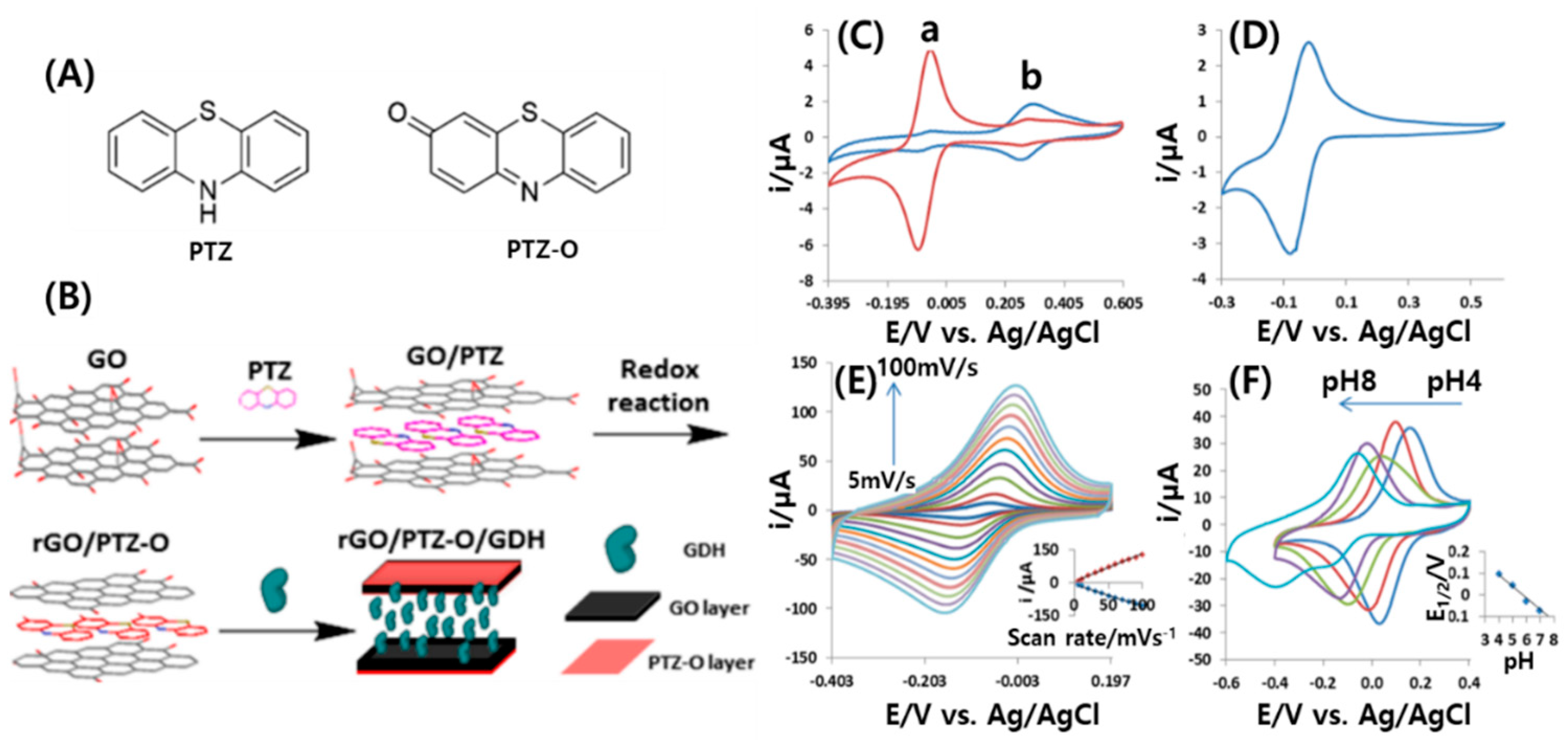
- Ravenna, Y.; Xia, L.; Gun, J.; Mikhaylov, A.A.; Medvedev, A.G.; Lev, O.; Alfonta, L. Biocomposite based on reduced graphene oxide film modified with phenothiazone and flavin adenine dinucleotide-dependent glucose dehydrogenase for glucose sensing and biofuel cell applications. Anal. Chem. 2015, 87, 9567–9571. [Google Scholar] [CrossRef]
- Benjamin, M.; Manoj, D.; Thenmozhi, K.; Bhagat, P.R.; Saravanakumar, D.; Senthilkumar, S. A bioinspired ionic liquid tagged cobalt-salophen complex for nonenzymatic detection of glucose. Biosens. Bioelectron. 2017, 91, 380–387. [Google Scholar] [CrossRef]
- Mazaheri, M.; Aashuri, H.; Simchi, A. Three-dimensional hybrid graphene/nickel electrodes on zinc oxide nanorod arrays as non-enzymatic glucose biosensors. Sensor Actuat B Chem. 2017, 251, 462–471. [Google Scholar] [CrossRef]
- Wang, C.; Sun, Y.L.; Yu, X.H.; Ma, D.Q.; Zheng, J.; Dou, P.; Cao, Z.Z.; Xu, X.H. Ag-Pt hollow nanoparticles anchored reduced graphene oxide composites for non-enzymatic glucose biosensor. J. Mater. Sci. Mater. El 2016, 27, 9370–9378. [Google Scholar] [CrossRef]
- Gao, W.; Tjiu, W.W.; Wei, J.C.; Liu, T.X. Highly sensitive nonenzymatic glucose and H2O2 sensor based on Ni(OH)(2)/electroreduced graphene oxide-Multiwalled carbon nanotube film modified glass carbon electrode. Talanta 2014, 120, 484–490. [Google Scholar] [CrossRef]
- Li, Y.; Fang, L.; Cheng, P.; Deng, J.; Jiang, L.; Huang, H.; Zheng, J. An electrochemical immunosensor for sensitive detection of Escherichia coli O157:H7 using C60 based biocompatible platform and enzyme functionalized Pt nanochains tracing tag. Biosens. Bioelectron. 2013, 49, 485–491. [Google Scholar] [CrossRef] [PubMed]
- Sherigara, B.S.; Kutner, W.D.; Souza, F. Electrocatalytic properties and sensor applications of fullerenes and carbon nanotubes. Electroanalysis 2003, 15, 753–772. [Google Scholar] [CrossRef]
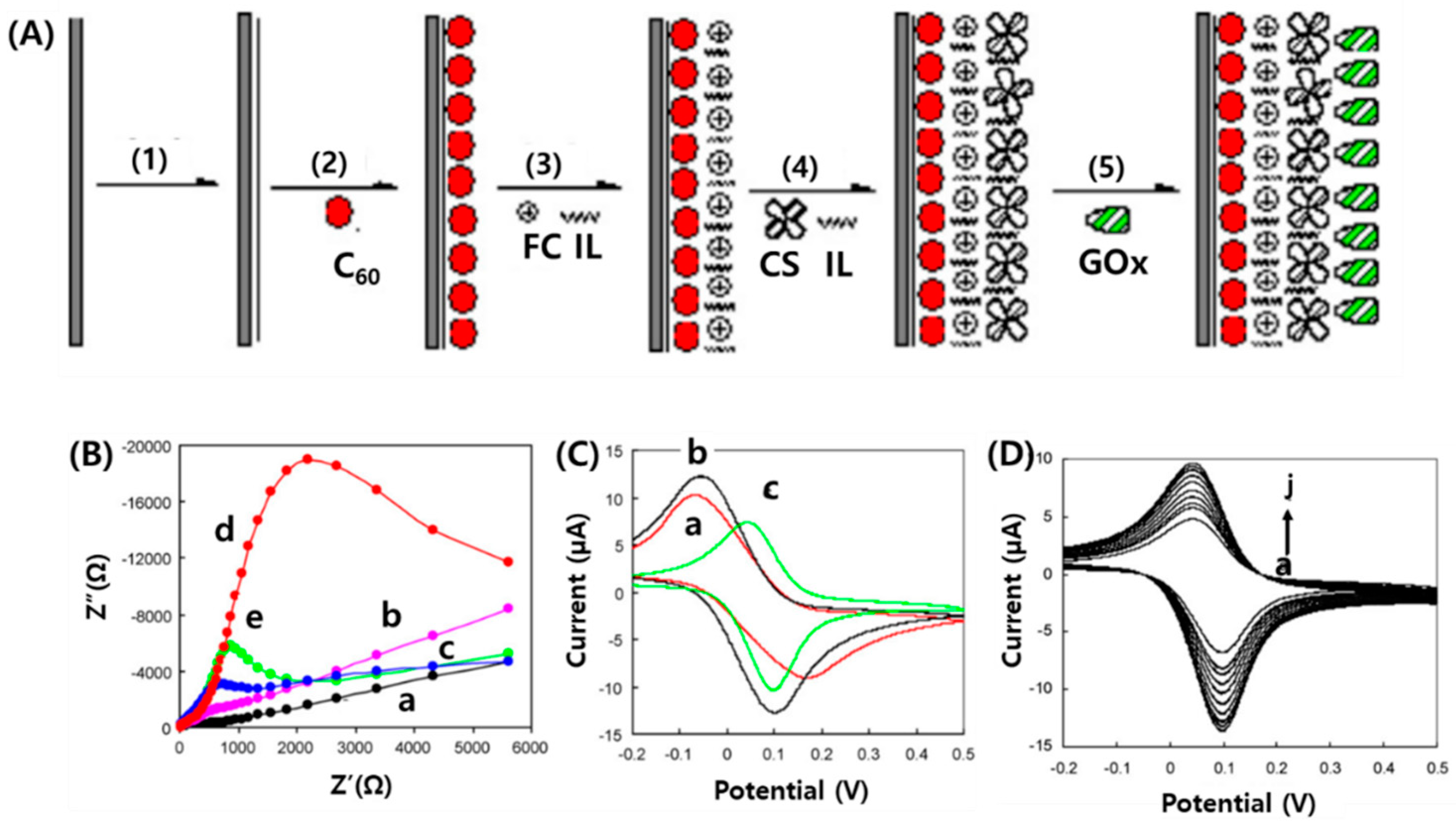
- Wei, Z.L.; Li, Z.J.; Sun, X.L.; Fang, Y.J.; Liu, J.K. Synergistic contributions of fullerene, ferrocene, chitosan and ionic liquid towards improved performance for a glucose sensor. Biosens. Bioelectron. 2010, 25, 1434–1438. [Google Scholar]
- Afreen, S.; Muthoosamy, K.; Manickam, S.; Hashim, U. Functionalized fullerene (C(6)(0)) as a potential nanomediator in the fabrication of highly sensitive biosensors. Biosens. Bioelectron. 2015, 63, 354–364. [Google Scholar] [CrossRef]
- Baena, J.R.; Gallego, M.; Valcarcel, M. Fullerenes in the analytical sciences. TrAC Trends Anal. Chem. 2002, 21, 187–198. [Google Scholar] [CrossRef]
- Sheng, Q.L.; Liu, R.X.; Zheng, J.B. Fullerene-nitrogen doped carbon nanotubes for the direct electrochemistry of hemoglobin and its application in biosensing. Bioelectrochemistry 2013, 94, 39–46. [Google Scholar] [CrossRef]
- Lanzellotto, C.; Favero, G.; Antonelli, M.L.; Tortolini, C.; Cannistraro, S.; Coppari, E.; Mazzei, F. Nanostructured enzymatic biosensor based on fullerene and gold nanoparticles: Preparation, characterization and analytical applications. Biosens. Bioelectron. 2014, 55, 430–437. [Google Scholar] [CrossRef]
- Han, J.; Zhuo, Y.; Chai, Y.Q.; Xiang, Y.; Yuan, R. New type of redox nanoprobe: C60-based nanomaterial and its application in electrochemical immunoassay for doping detection. Anal. Chem. 2015, 87, 1669–1675. [Google Scholar] [CrossRef]
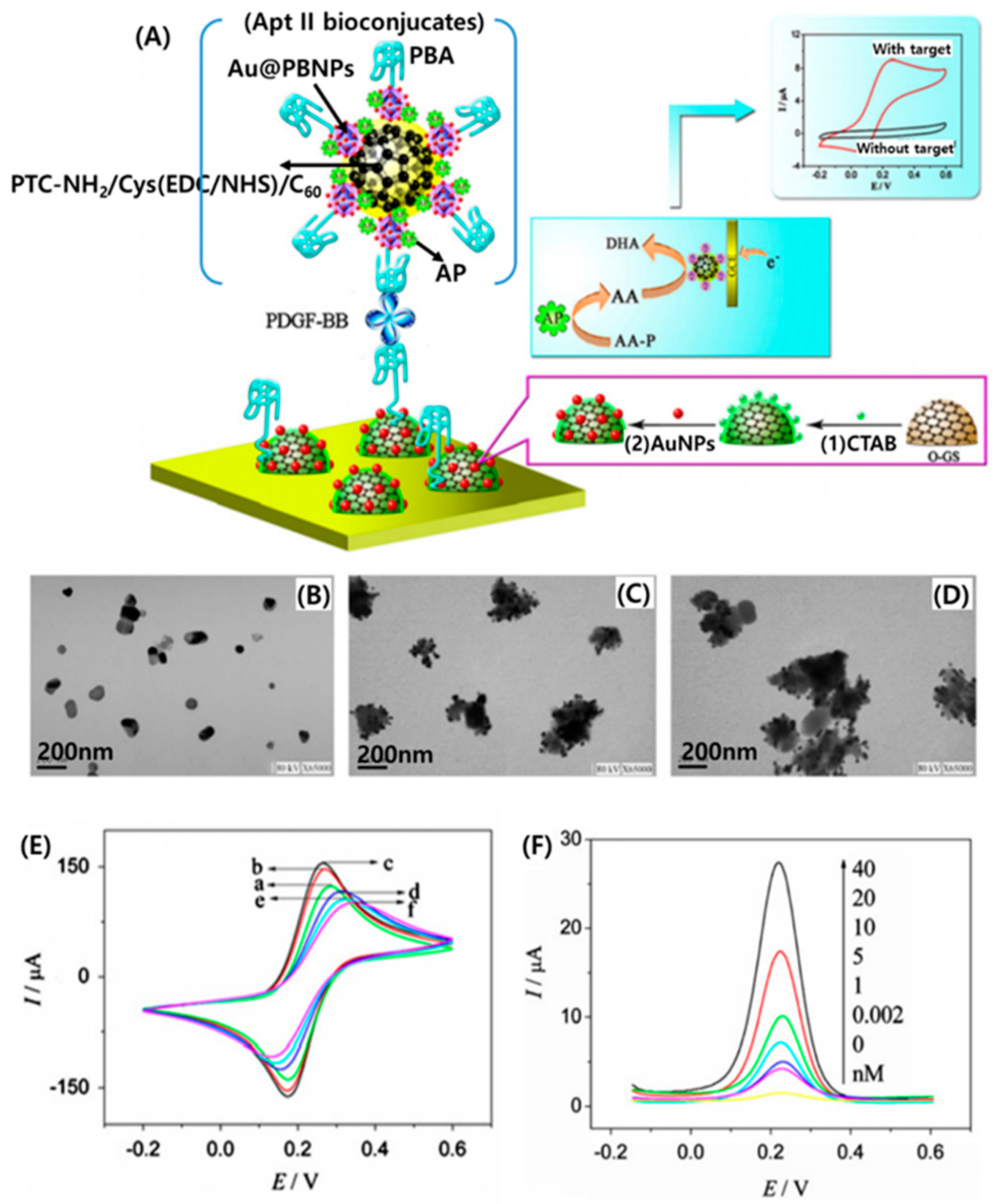
- Han, J.; Zhuo, Y.; Chai, Y.; Yuan, R.; Xiang, Y.; Zhu, Q.; Liao, N. Multi-labeled functionalized C(6)(0) nanohybrid as tracing tag for ultrasensitive electrochemical aptasensing. Biosens. Bioelectron. 2013, 46, 74–79. [Google Scholar] [CrossRef] [PubMed]
- Wang, Q.; Song, Y.; Xie, H.; Chai, Y.; Yuan, Y.; Yuan, R. L-cysteine induced hemin/G-quadruplex concatemers electrocatalytic amplification with Pt-Pd supported on fullerene as a nanocarrier for sensing the spore wall protein of Nosema bombycis. Chem. Commun (Camb) 2015, 51, 1255–1258. [Google Scholar] [CrossRef]
- Mazloum-Ardakani, M.; Hosseinzadeh, L.; Khoshroo, A. Label-free electrochemical immunosensor for detection of tumor necrosis factor et based on fullerene-functionalized carbon nanotubes/ionic liquid. J. Electroanal. Chem. 2015, 757, 58–64. [Google Scholar] [CrossRef]
- Geckeler, K.E.; Samal, S. Syntheses and properties of macromolecular fullerenes, a review. Polym. Int. 1999, 48, 743–757. [Google Scholar] [CrossRef]
- Goodarzi, S.; Da Ros, T.; Conde, J.; Sefat, F.; Mozafari, M. Fullerene: Biomedical engineers get to revisit an old friend. Mater. Today 2017, 20, 460–480. [Google Scholar] [CrossRef]
- Curl, R.F.; Smalley, R.E. Probing c60. Science 1988, 242, 1017–1022. [Google Scholar] [CrossRef] [PubMed]
- Boorum, M.M.; Vasil’ev, Y.V.; Drewello, T.; Scott, L.T. Groundwork for a rational synthesis of C60: Cyclodehydrogenation of a C60H30 polyarene. Science 2001, 294, 828–831. [Google Scholar] [CrossRef]
- Yanez-Sedeno, P.; Campuzano, S.; Pingarron, J.M. Fullerenes in Electrochemical Catalytic and Affinity Biosensing: A Review. C J. Carbon Res. 2017, 3, 21. [Google Scholar] [CrossRef]
- Pilehvar, S.; De Wael, K. Recent Advances in Electrochemical Biosensors Based on Fullerene-C60 Nano-Structured Platforms. Biosensors (Basel) 2015, 5, 712–735. [Google Scholar] [CrossRef]
- Barberis, A.; Spissu, Y.; Fadda, A.; Azara, E.; Bazzu, G.; Marceddu, S.; Angioni, A.; Sanna, D.; Schirra, M.; Serra, P.A. Simultaneous amperometric detection of ascorbic acid and antioxidant capacity in orange, blueberry and kiwi juice, by a telemetric system coupled with a fullerene- or nanotubes-modified ascorbate subtractive biosensor. Biosens. Bioelectron. 2015, 67, 214–223. [Google Scholar] [CrossRef]


| Method | Arc Discharge | Laser Ablation | CVD |
|---|---|---|---|
| Yield rate | >75% | >75% | >75% |
| SWCNT or MWCNT | Both | Both | Both |
| Advantages | Simple, inexpensive, high-quality nanotubes | Relatively high purity, room-temperature synthesis | Simple, low temperature, high purity, large-scale production, aligned growth possible |
| Disadvantages | High temperature, purification required, tangled nanotubes | Method limited to the lab scale, crude product purification required | Production limited to MWCNTs, defects |
© 2020 by the authors. Licensee MDPI, Basel, Switzerland. This article is an open access article distributed under the terms and conditions of the Creative Commons Attribution (CC BY) license (http://creativecommons.org/licenses/by/4.0/).
Share and Cite
Hwang, H.S.; Jeong, J.W.; Kim, Y.A.; Chang, M. Carbon Nanomaterials as Versatile Platforms for Biosensing Applications. Micromachines 2020, 11, 814. https://doi.org/10.3390/mi11090814
Hwang HS, Jeong JW, Kim YA, Chang M. Carbon Nanomaterials as Versatile Platforms for Biosensing Applications. Micromachines. 2020; 11(9):814. https://doi.org/10.3390/mi11090814
Chicago/Turabian StyleHwang, Hye Suk, Jae Won Jeong, Yoong Ahm Kim, and Mincheol Chang. 2020. "Carbon Nanomaterials as Versatile Platforms for Biosensing Applications" Micromachines 11, no. 9: 814. https://doi.org/10.3390/mi11090814
APA StyleHwang, H. S., Jeong, J. W., Kim, Y. A., & Chang, M. (2020). Carbon Nanomaterials as Versatile Platforms for Biosensing Applications. Micromachines, 11(9), 814. https://doi.org/10.3390/mi11090814