Suppression of Surface Waviness Error of Fresnel Micro-Structured Mold by Using Non-Integer Rotation Speed Ratio in Parallel Grinding Process


Abstract
1. Introduction
2. Development of Surface Waviness Model
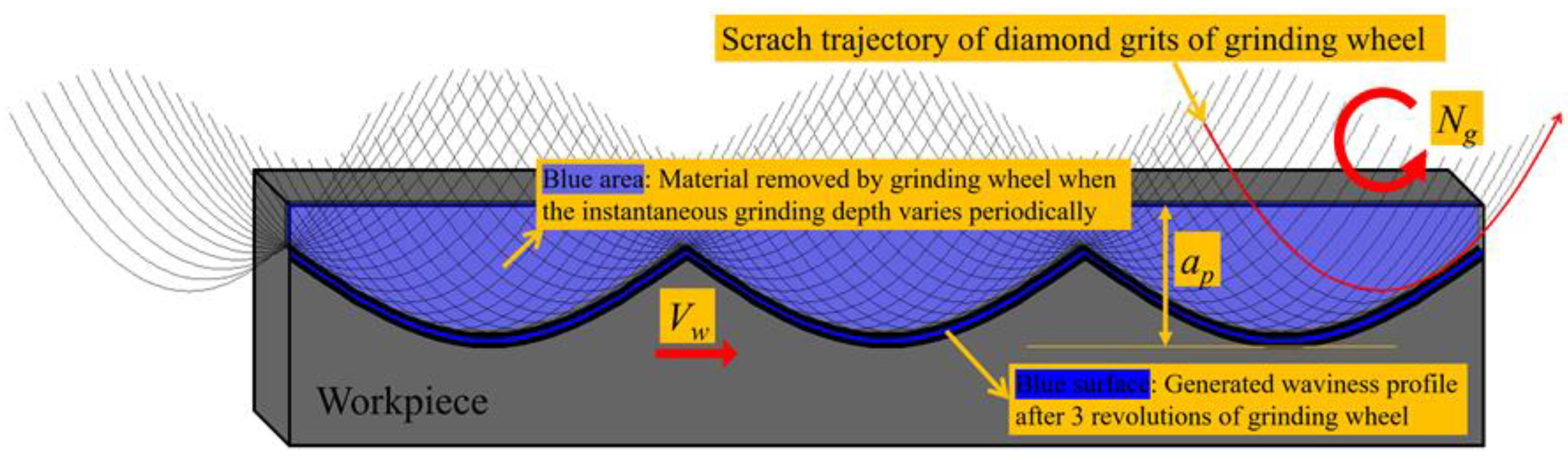
2.1. Kinematical Analysis of the Parallel Grinding Process
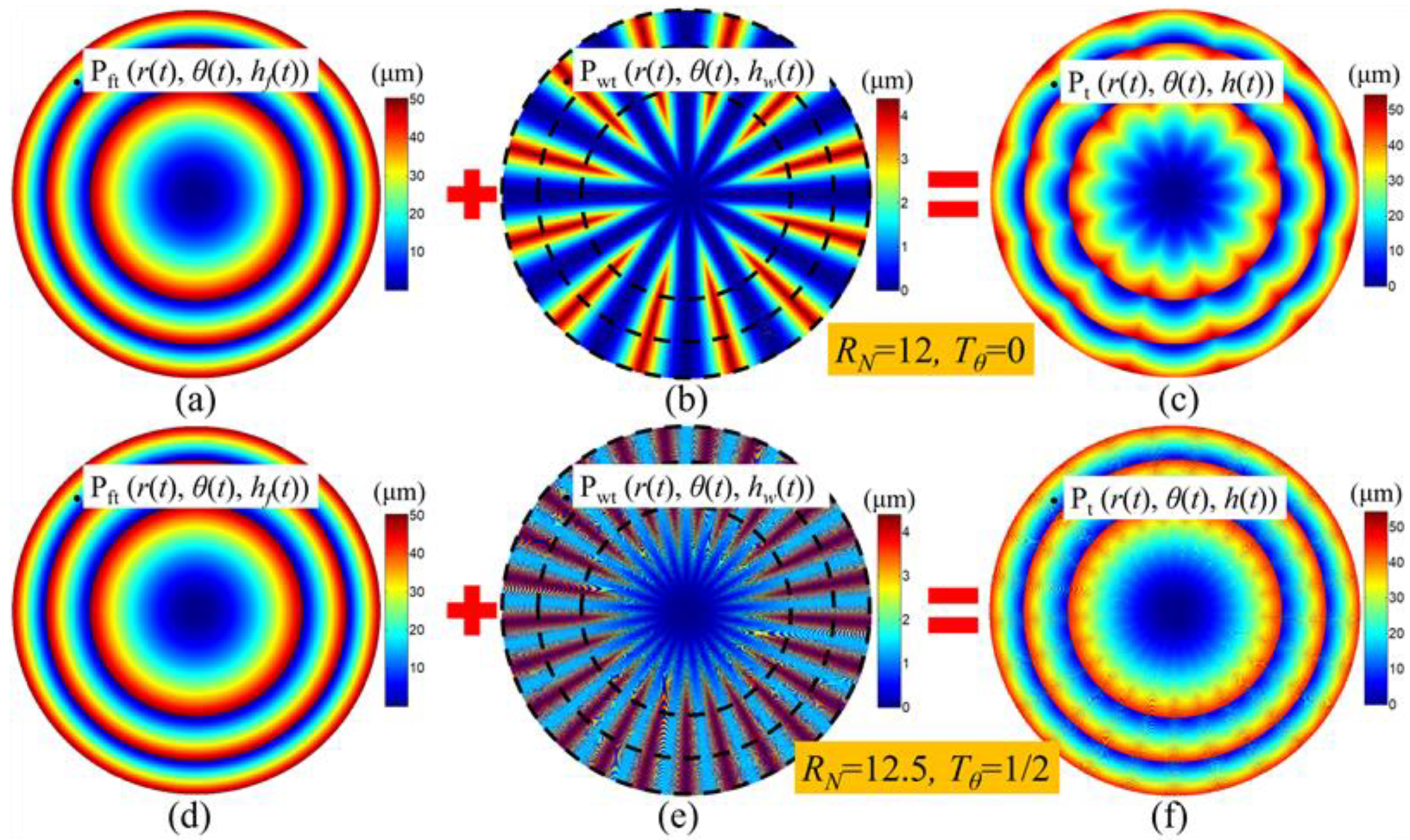
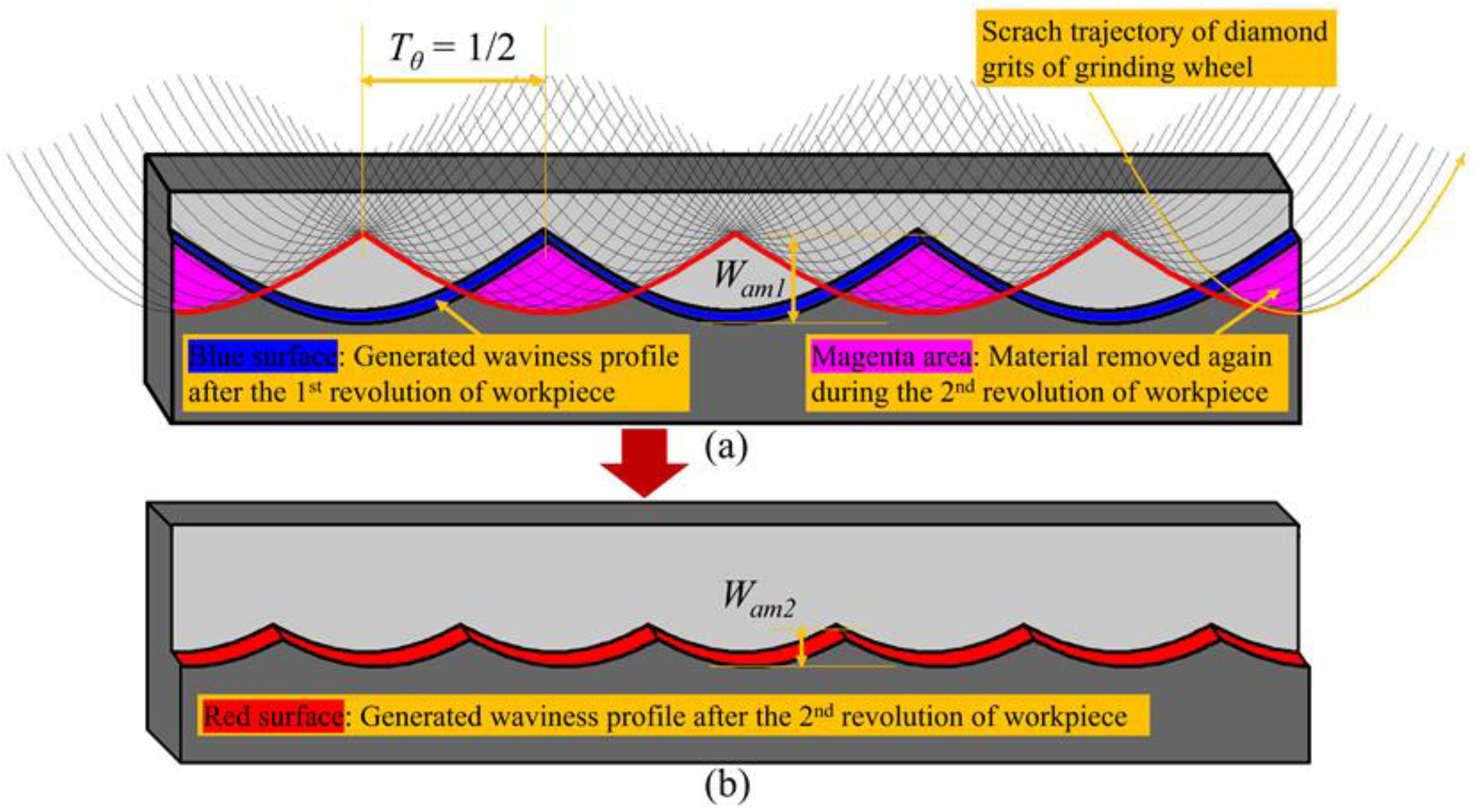
2.2. Modeling of the Surface Waviness Topography
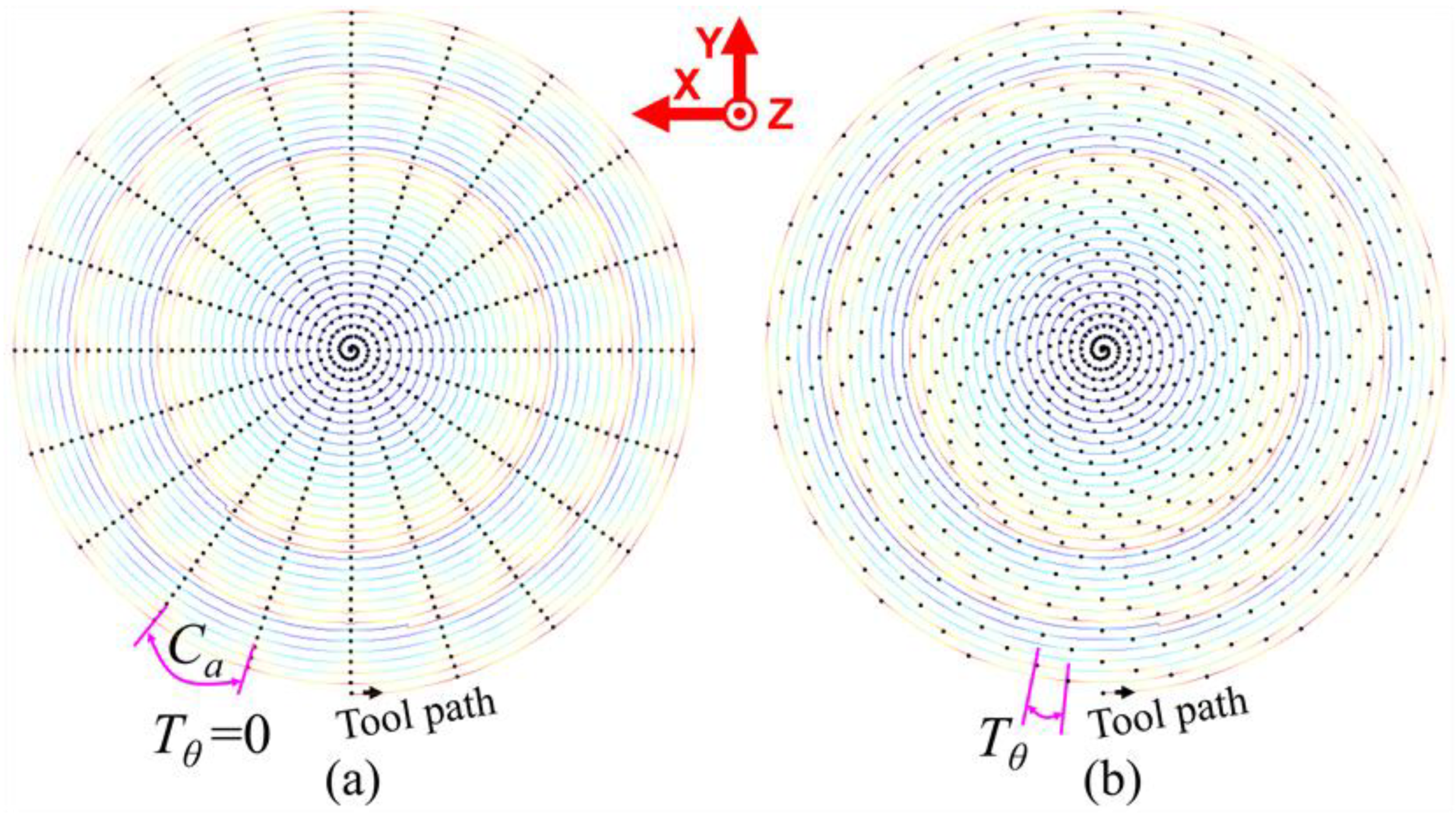
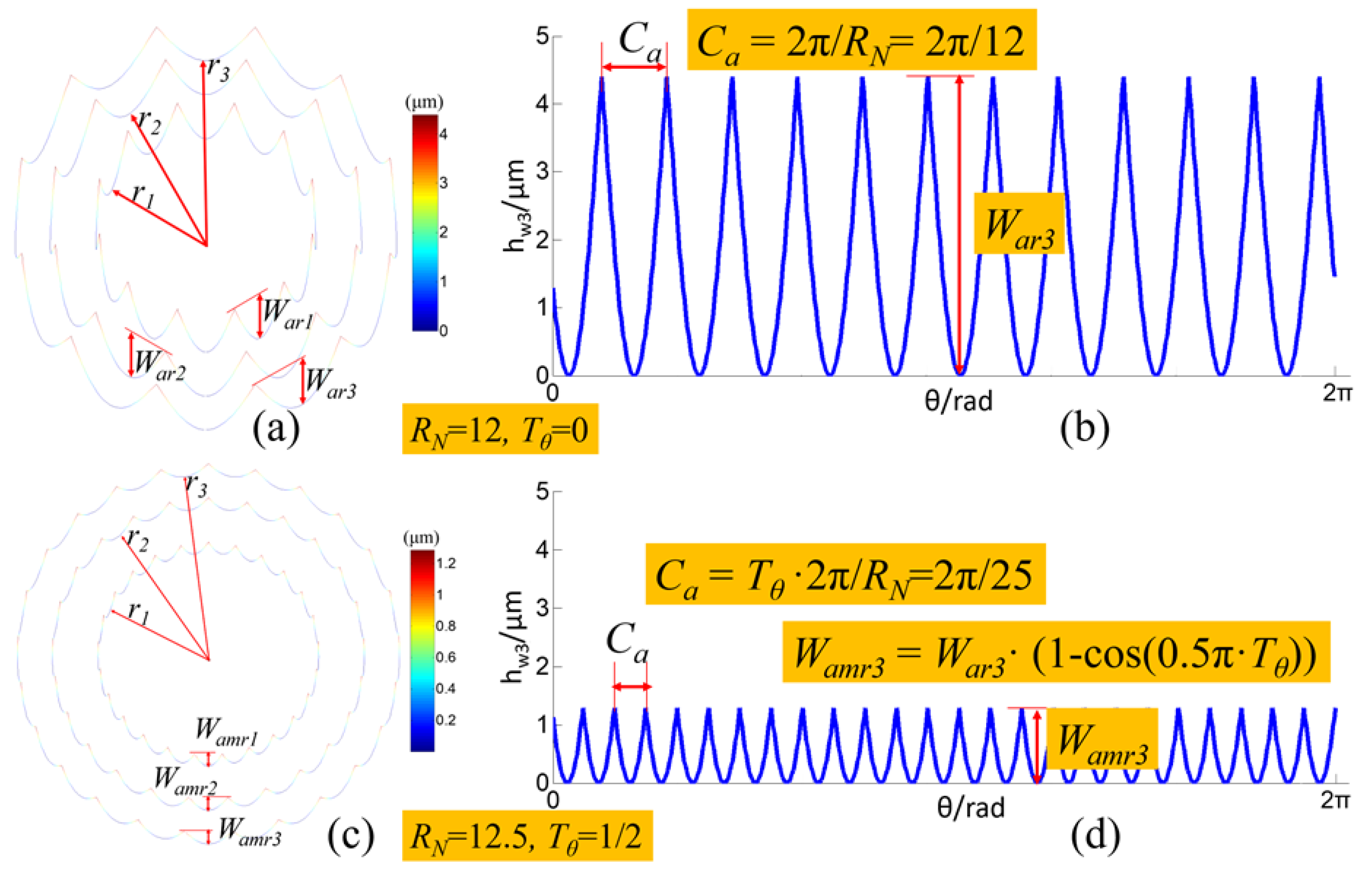
2.3. Modeling of the Circular Waviness Profiles
- (1)
- When RSR RN is integer and the wave-shift value Tθ = 0, the circular waviness profile on the edge of the i-th circle surface of Fresnel micro-structured mold is:
- (2)
- When RSR RN is non-integer and the wave-shift value Tθ = (q is integer, 2 ≤ q ≤ round(lg/fpr)), the circular waviness profile on the edge of the i-th circle surface of the Fresnel micro-structured mold:amplitude of the circular waviness profile:
3. Experiment and Simulation Results
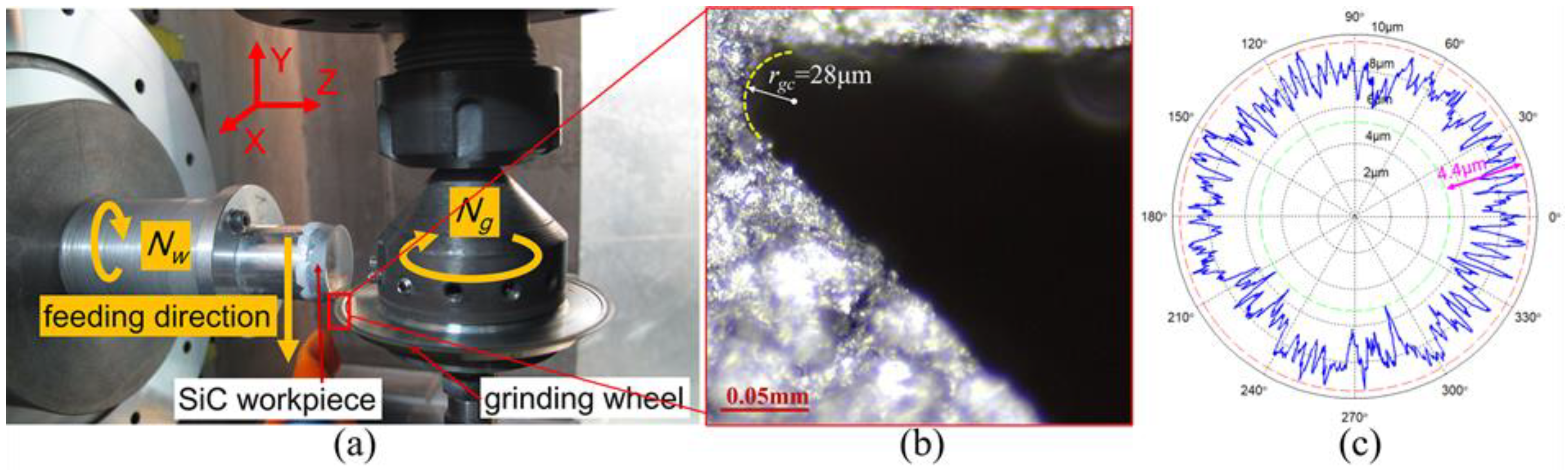
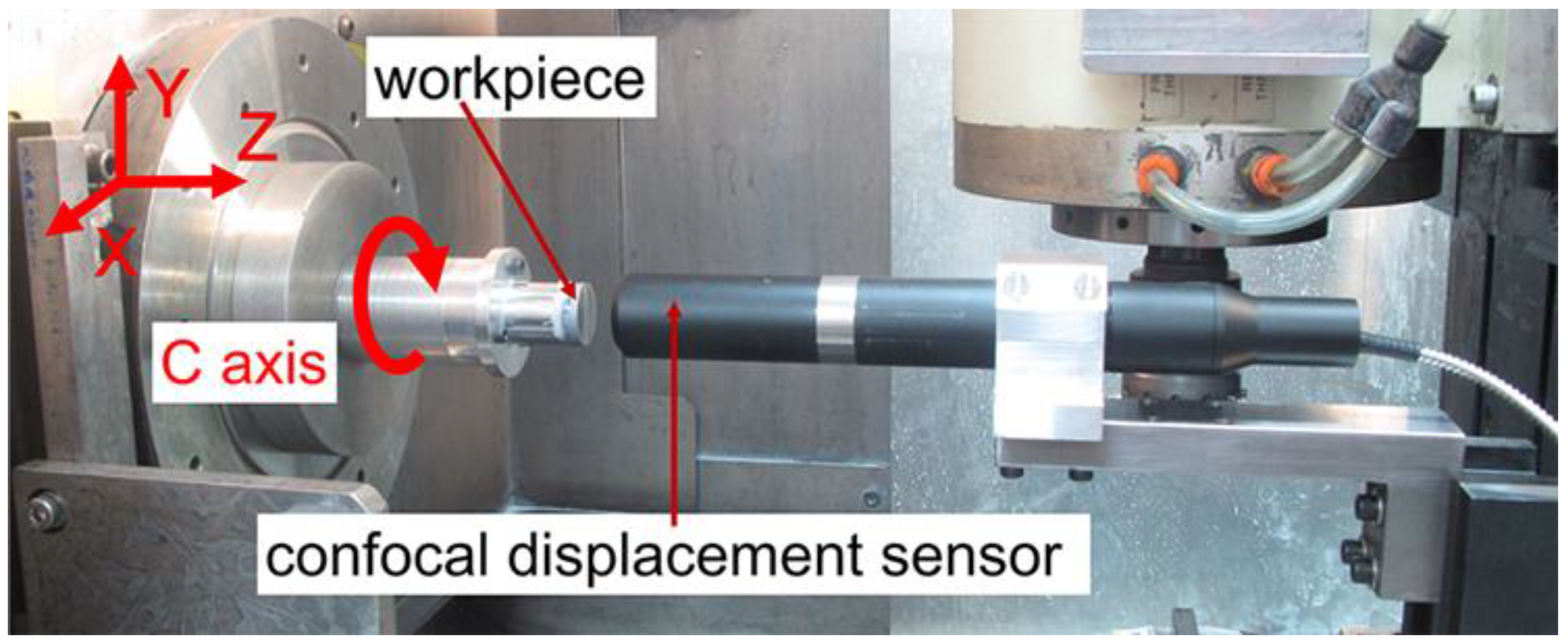
3.1. Experimental Setup and Parameters Design
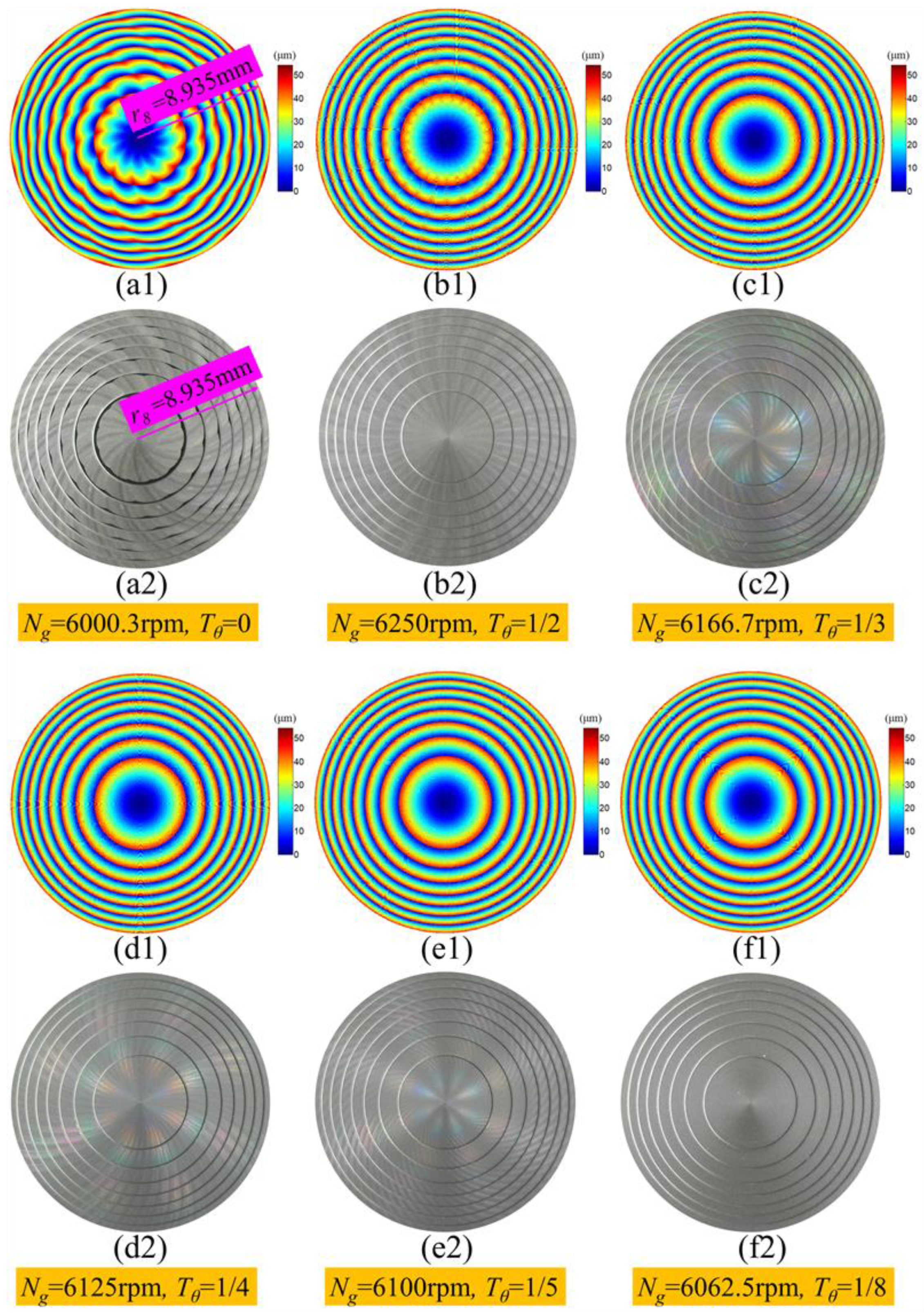
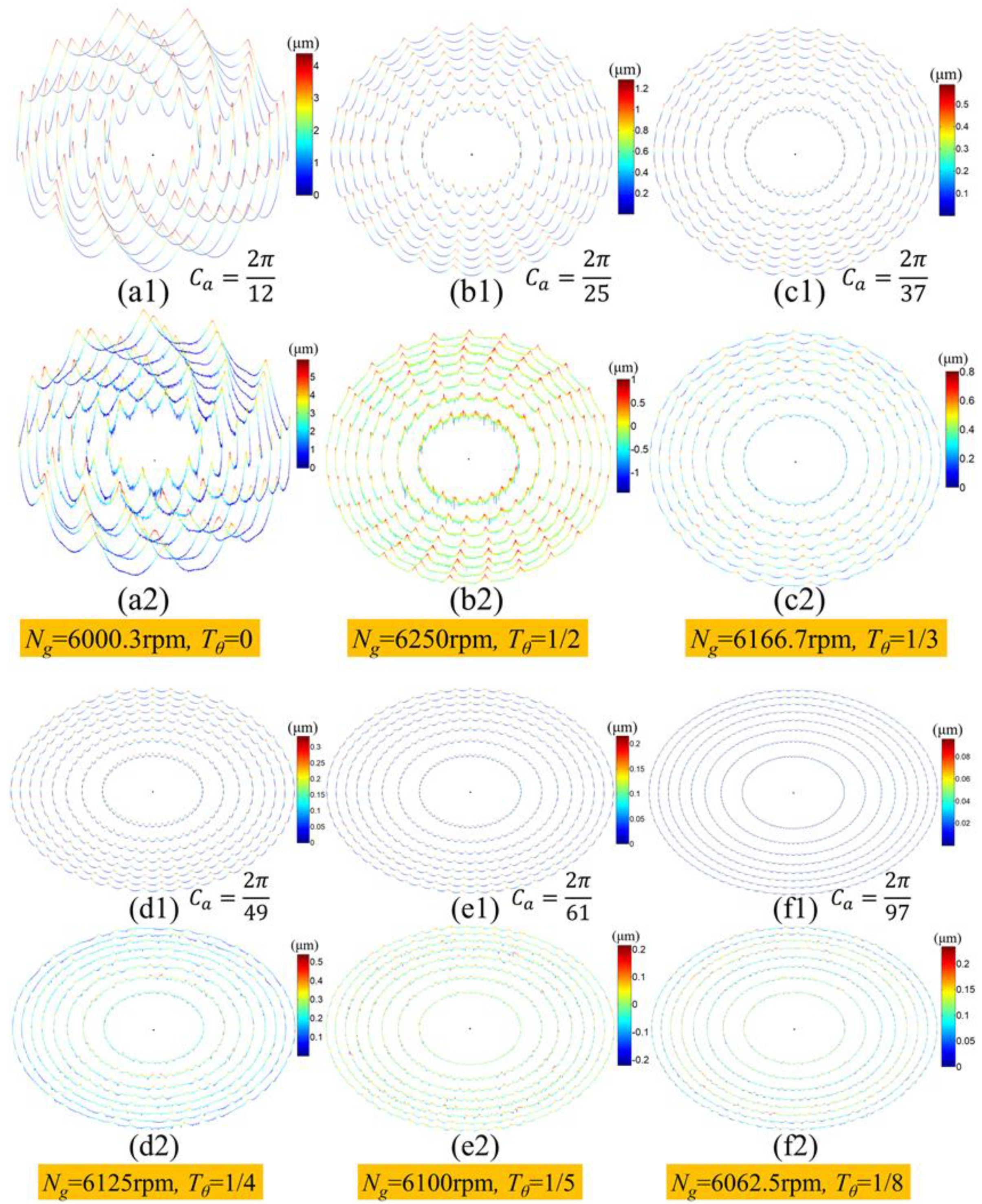
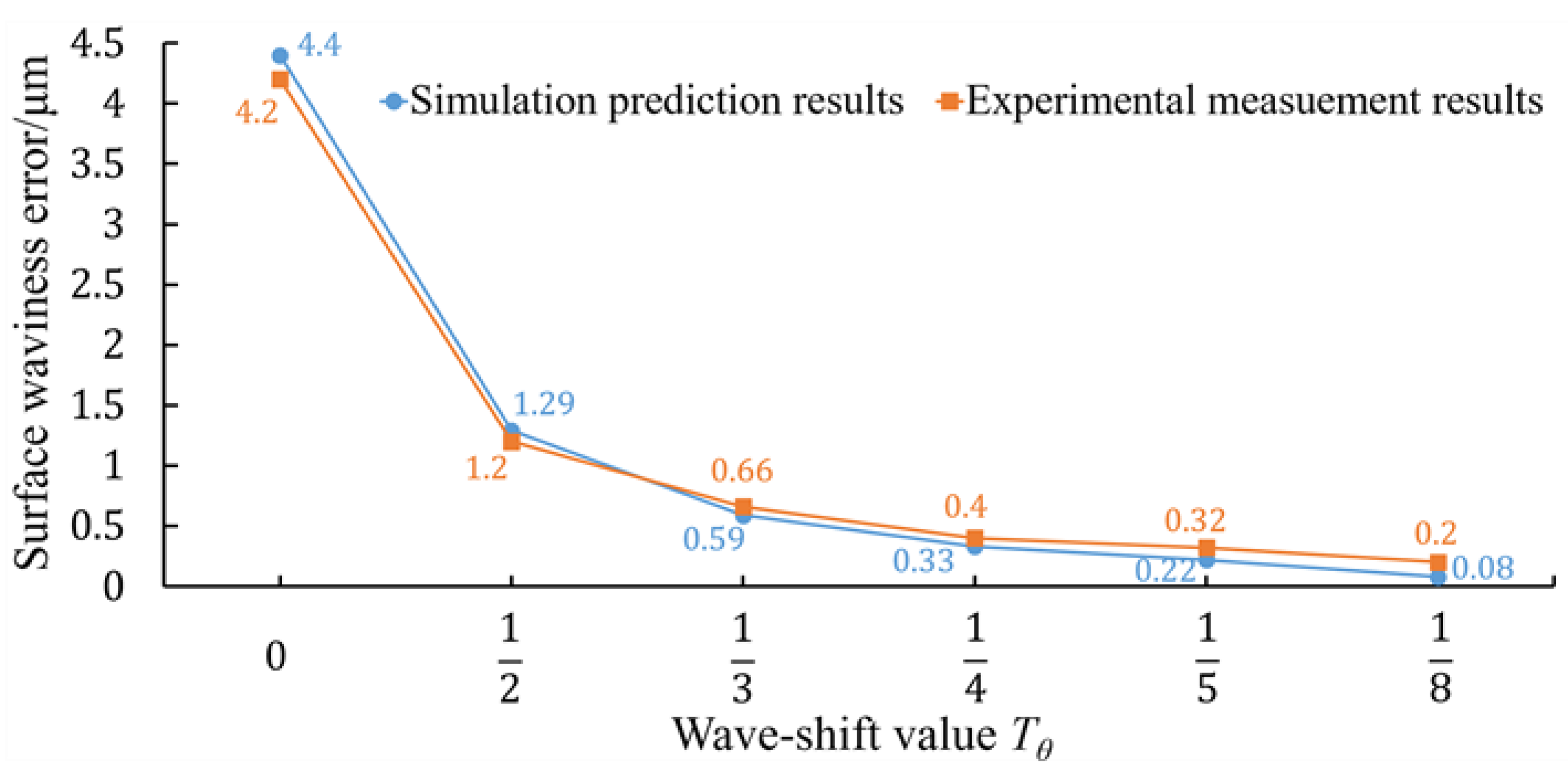
3.2. Analysis of Experiment and Simulation Results
4. Conclusions
- (1)
- Based on the surface waviness simulation model of the ground plane workpiece and the grinding kinematics theory, the simulation model of the surface waviness topography of the ground Fresnel micro-structured mold was developed and experimentally verified. As a typical example, it could provide a solution to help extend the ground surface waviness simulation model to other complexed axisymmetric components, such as aspheric lens, ball valve and cylindrical components.
- (2)
- Based on the interference-overlapping effect of the adjacent waviness profiles, the theoretical simulation model of the circular waviness profiles of the ground Fresnel micro-structured mold was firstly developed and experimentally verified. Compared with the simulated surface waviness topography, it could more clearly and three-dimensionally illustrate the distribution of waviness error at a different radial position of the ground workpiece surface, and more distinctly show the suppression effect of the surface waviness error by using different wave-shift values. The experimental results showed that the surface waviness error could be reduced by 95%, when slightly adjusting the grinding wheel’s rotation speed to achieve a proper wave-shift value.
- (3)
- The proposed simulation model of the surface waviness topography and circular waviness profiles could be used to predict the surface waviness error of the ground Fresnel micro-structured mold and guide the selection of grinding parameters. Using non-integer RSR and a proper wave-shift value could significantly suppress the surface waviness error and improve the surface quality and uniformity in parallel to the grinding process of complexed axisymmetric components, without decreasing the production efficiency.
Author Contributions
Funding
Conflicts of Interest
Abbreviations
| ap (μm) | Grinding depth |
| Ca (°) | Angular period value of the surface waviness of Fresnel micro-structured mold |
| fpr (mm) | Cross-feeding distance per revolution of workpiece |
| ge (mm) | Radial run-out error of grinding wheel |
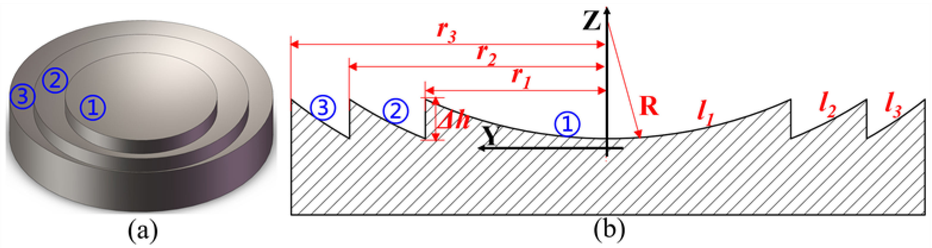
| Δh (μm) | Step height of Fresnel micro-structured mold |
| lg (mm) | Contact length between grinding wheel and workpiece |
| b | Total number of circle surfaces of Fresnel micro-structured mold |
| Ng (rpm) | Rotation speed of grinding wheel |
| Nw (rpm) | Rotation speed of workpiece |
| R (mm) | Spherical radius of Fresnel micro-structured mold |
| RN | Rotation speed ratio (RSR) of grinding wheel and workpiece |
| rg (mm) | Radius of grinding wheel |
| rgc (μm) | Tip nose radius of grinding wheel |
| ri (mm) | Caliber radius of the i-th circle surface of Fresnel micro-structured mold |
| rwc (mm) | Critical radial position on workpiece in parallel grinding process of Fresnel micro-structured mold |
| Tθ | Wave-shift value |
| twa (min) | The total machining time of a complete feeding procedure from the edge to the center of Fresnel micro-structured mold in parallel grinding process |
| Vf (mm/min) | Feed rate of grinding wheel |
| Wa (μm) | Amplitude of the surface waviness of Fresnel micro-structured mold |
| Wamri (μm) | Amplitude of the surface waviness profile at the edge of the i-th circle surface of Fresnel micro-structured mold (non-integer RSR) |
| Wari (μm) | Amplitude value of the surface waviness profile at the edge of the i-th circle surface of Fresnel micro-structured mold (integer RSR) |
| Wat (μm) | Amplitude of the generated surface waviness on Fresnel micro-structured mold at time t during the feeding procedure |
References
- Zhang, S.; Zhou, Y.; Zhang, H.; Xiong, Z.; To, S. Advances in ultra-precision machining of micro-structured functional surfaces and their typical applications. Int. J. Mach. Tools Manuf. 2019, 142, 16–41. [Google Scholar] [CrossRef]
- Roeder, M.; Guenther, T.; Zimmermann, A. Review on fabrication technologies for optical mold inserts. Micromachines. 2019, 10, 233. [Google Scholar] [CrossRef]
- Aničin, B.; Babović, V.; Davidović, D. Fresnel lenses. Am. J. Phys. 1989, 57, 312–316. [Google Scholar] [CrossRef]
- Davison, J.; Simpson, M. History and development of the apodized diffractive intraocular lens. J. Cataract. Ref. Surg. 2006, 32, 849–858. [Google Scholar] [CrossRef] [PubMed]
- Davis, A.; Bush, R.; Harvey, J.; Foley, M.F. P-95: Fresnel Lenses in Rear Projection Displays. In SID Symposium Digest of Technical Papers; Blackwell Publishing: Oxford, UK, 2001; Volume 32, pp. 934–937. [Google Scholar] [CrossRef]
- Noda, T. Temperature Compensation with DOE for Zoom Lens. Proceedings Volume 11106, Zoom Lenses VI, 111060C, Proceedings of the SPIE Optical Engineering + Applications, San Diego, CA, USA, 10 September 2019; SPIE: Bellingham, WA, USA, 2019. [Google Scholar] [CrossRef]
- Chen, F.; Wang, K.; Qin, Z.; Wu, D.; Luo, X.; Liu, S. Design method of high-efficient LED headlamp lens. Opt. Express 2010, 18, 20926–20938. [Google Scholar] [CrossRef] [PubMed]
- Xie, W.; Dai, Y.; Wang, R.Z.; Sumathy, K. Concentrated solar energy applications using Fresnel lenses: A review. Renew. Sustain. Energ. Rev. 2011, 15, 2588–2606. [Google Scholar] [CrossRef]
- Huang, C.Y.; Chen, C.C.; Chou, H.Y.; Chou, C.P. Fabrication of fresnel lens by glass molding technique. Opt. Rev. 2013, 20, 202–204. [Google Scholar] [CrossRef]
- Lu, Y.; Chen, F.; Wu, X.; Zhou, C.; Lou, Y.; Li, L. Fabrication of micro-structured polymer by micro injection molding based on precise micro-ground mold core. Micromachines 2019, 10, 253. [Google Scholar] [CrossRef]
- Zhou, T.; Zhu, Z.; Liu, X.; Liang, Z.; Wang, X. A review of the precision glass molding of Chalcogenide glass (ChG) for infrared optics. Micromachines 2018, 9, 337. [Google Scholar] [CrossRef]
- Roeder, M.; Drexler, M.; Rothermel, T.; Meissner, T.; Guenther, T.; Zimmermann, A. Injection Compression Molded Microlens Arrays for Hyperspectral Imaging. Micromachines 2018, 9, 355. [Google Scholar] [CrossRef]
- Zhang, Q.; Zhao, Q.; To, S.; Guo, B.; Rao, Z. Precision machining of ‘water-drop’ surface by single point diamond grinding. Precis. Eng. 2018, 51, 190–197. [Google Scholar] [CrossRef]
- Guo, B.; Zhao, Q. Ultrasonic vibration assisted grinding of hard and brittle linear micro-structured surfaces. Precis. Eng. 2017, 48, 98–106. [Google Scholar] [CrossRef]
- Zhao, W.; Hong, H.; Wang, H. Mechanism of Unstable Material Removal Modes in Micro Cutting of Silicon Carbide. Micromachines 2019, 10, 696. [Google Scholar] [CrossRef]
- Brinksmeier, E.; Mutlugünes, Y.; Klocke, F.; Aurich, J.C.; Shore, P.; Ohmori, H. Ultra-precision grinding. CIRP Ann. 2010, 59, 652–671. [Google Scholar] [CrossRef]
- Guo, B.; Zhao, Q.; Jackson, M.J. Precision grinding of binderless ultrafine tungsten carbide (WC) microstructured surfaces. Int. J. Adv. Manuf. Technol. 2013, 64, 727–735. [Google Scholar] [CrossRef]
- Guo, B.; Zhao, Q. Wheel normal grinding of hard and brittle materials. Int. J. Adv. Manuf. Technol. 2015, 79, 873–880. [Google Scholar] [CrossRef]
- Bletek, T.; Klocke, F.; Hünten, M.; Dambon, O. Dressing of Grinding Wheels for Ultra Precision Grinding of Diffractive Structures in Tungsten Carbide Molds. Key Eng. Mater. 2014, 625, 161–166. [Google Scholar] [CrossRef]
- Suzuki, H.; Okada, M.; Yamagata, Y.; Morita, S.; Higuchi, T. Precision grinding of structured ceramic molds by diamond wheel trued with alloy metal. CIRP Ann. 2012, 61, 283–286. [Google Scholar] [CrossRef]
- Li, Z.; Zhang, F.; Luo, X.; Guo, X.; Cai, Y.; Chang, W.; Sun, J. A New Grinding Force Model for Micro Grinding RB-SiC Ceramic with Grinding Wheel Topography as an Input. Micromachines 2018, 9. [Google Scholar] [CrossRef]
- ISO 10110-8:2019. Optics and Photonics—Preparation of Drawings for Optical Elements and Systems—Part 8: Surface Texture; International Organization for Standardization: Geneva, Switzerland, 2019; p. 23. [Google Scholar]
- ISO 25178-2:2012. Geometrical Product Specifications (GPS)—Surface Texture: Areal—Part 2: Terms, Definitions and Surface Texture Parameters; International Organization for Standardization: Geneva, Switzerland, 2012; p. 47. [Google Scholar]
- ASME B46.1-2019. Surface Texture (Surface Roughness, Waviness, and Lay); American Society of Mechanical Engineers: New York, NY, USA, 2020; p. 144. [Google Scholar]
- Baker, L. Metrics for High-Quality Specular Surfaces; SPIE PRESS: Bellingham, WA, USA, 2004; pp. 41–42. [Google Scholar]
- He, C.L.; Zong, W.J.; Xue, C.X.; Sun, T. An accurate 3D surface topography model for single-point diamond turning. Int. J. Mach. Tools Manuf. 2018, 134, 42–68. [Google Scholar] [CrossRef]
- Zhang, S.; Yu, J.; To, S.; Xiong, Z. A theoretical and experimental study of spindle imbalance induced forced vibration and its effect on surface generation in diamond turning. Int. J. Mach. Tools Manuf. 2018, 133, 61–71. [Google Scholar] [CrossRef]
- Lin, X.; Liu, J.; Ke, X. Investigation of waviness error in surface grinding of large axisymmetric aspheric lenses. Proc. Inst. Mech. Eng. Part B J. Eng. Manuf. 2016, 230, 1195–1202. [Google Scholar] [CrossRef]
- Huo, F.; Kang, R.; Li, Z.; Guo, D.M. Origin, modeling and suppression of grinding marks in ultra precision grinding of silicon wafers. Int. J. Mach. Tools Manuf. 2013, 66, 54–65. [Google Scholar] [CrossRef]
- Trmal, G.; Holesovsky, F. Wave-shift and its effect on surface quality in super-abrasive grinding. Int. J. Mach. Tools Manuf. 2001, 41, 979–989. [Google Scholar] [CrossRef]
- Pan, Y.; Zhao, Q.; Guo, B.; Chen, B.; Wang, J.; Wu, X. An investigation of the surface waviness features of ground surface in parallel grinding process. Int. J. Mech. Sci. 2020, 170, 105351. [Google Scholar] [CrossRef]
- Meneghello, R.; Concheri, G.; Savio, G.; Comelli, D. Surface and geometry error modeling in brittle mode grinding of ophthalmic lenses moulds. Int. J. Mach. Tools Manuf. 2006, 46, 1662–1670. [Google Scholar] [CrossRef]
- Suzuki, H.; Okada, M.; Lin, W.; Morita, S.; Yamagata, Y.; Hanada, H.; Araki, H.; Kashima, S. Fine finishing of ground DOE lens of synthetic silica by magnetic field-assisted polishing. CIRP Ann. 2014, 63, 313–316. [Google Scholar] [CrossRef]
- Guo, J.; Jong, H.J.H.; Kang, R.; Guo, D. Novel localized vibration-assisted magnetic abrasive polishing method using loose abrasives for V-groove and Fresnel optics finishing. Opt. Express 2018, 26, 11608–11619. [Google Scholar] [CrossRef]
- Badger, J.; Murphy, S.; O’Donnell, G. The effect of wheel eccentricity and run-out on grinding forces, waviness, wheel wear and chatter. Int. J. Mach. Tools Manuf. 2011, 51, 766–774. [Google Scholar] [CrossRef]
- Kuriyagawa, T.; Yoshihara, N.; Saeki, M.; Syoji, K. Nano-Topography Characterization of Axisymmetrical Aspherical Ground Surfaces In Key Engineering Materials; Trans Tech Publication: Baech, Switzerland, 2003; Volume 238, pp. 125–130. [Google Scholar] [CrossRef]
- Yoshihara, N.; Kuriyagawa, T.; Ono, H.; Syoji, K. Nano-topography on axisymmetric aspherical ground surfaces. Int. J. Manuf. Technol. Manag. 2006, 9, 51–63. [Google Scholar] [CrossRef]
- Chen, S.; Cheung, C.F.; Zhang, F.; Ting, H.L.; Zhao, C. Theoretical and experimental investigation of a tool path control strategy for uniform surface generation in ultra-precision grinding. Int. J. Adv. Manuf. Technol. 2019, 103, 4307–4315. [Google Scholar] [CrossRef]
- Chen, S.; Cheung, C.F.; Zhang, F.; Liu, M. Optimization of Tool Path for Uniform Scallop-Height in Ultra-precision Grinding of Free-form Surfaces. Nanomanuf. Metrol. 2019, 2, 215–224. [Google Scholar] [CrossRef]
- Suzuki, H.; Higuchi, T.; Wajima, N.; Kitajima, T.; Okuyama, S.; Yamazaki, H. Precision grinding of micro fresnel lens molding die-Feasibility study on precision grinding of tungsten carbide. J. Jpn. Soc. Precis. Eng. 1999, 65, 1163–1168. [Google Scholar] [CrossRef][Green Version]
- Chen, B.; Li, S.; Deng, Z.; Guo, B.; Zhao, Q. Grinding marks on ultra-precision grinding spherical and aspheric surfaces. Int. J. Precis. Eng. Manuf. Green Tehnol. 2017, 4, 419–429. [Google Scholar] [CrossRef]
- Pei, Z. A study on surface grinding of 300 mm silicon wafers. Int. J. Mach. Tools Manuf. 2002, 42, 385–393. [Google Scholar] [CrossRef]
- Pei, Z.; Fisher, G.R.; Bhagavat, M.; Kassir, S. A grinding-based manufacturing method for silicon wafers: An experimental investigation. Int. J. Mach. Tools Manuf. 2005, 45, 1140–1151. [Google Scholar] [CrossRef]
- Tong, S.; Gracewski, S.; Funkenbusch, P. Periodic Scratch Marks on Ground Surfaces. Frontiers in Optics 2004/Laser Science XXII/Diffractive Optics and Micro-Optics/Optical Fabrication and Testing; Rochester: New York, NY, USA; Optical Society of America: Washington, DC, USA, 2004. [Google Scholar] [CrossRef]
- Fricker, D.; Speight, A.; Pearce, T. The modelling of roundness in cylindrical plunge grinding to incorporate wave shift and external vibration effects. Proc. Inst. Mech. Eng. Part B J. Eng. Manuf. 2006, 220, 1347–1358. [Google Scholar] [CrossRef]
- Chen, B.; Guo, B.; Zhao, Q. An investigation into parallel and cross grinding of aspheric surface on monocrystal silicon. Int. J. Adv. Manuf. Technol. 2015, 80, 737–746. [Google Scholar] [CrossRef]
- Hwang, Y.; Kuriyagawa, T.; Lee, S. Wheel curve generation error of aspheric microgrinding in parallel grinding method. Int. J. Mach. Tools Manuf. 2006, 46, 1929–1933. [Google Scholar] [CrossRef]
- Saeki, M.; Kuriyagawa, T.; Syoji, K. Machining of Aspherical Molding Dies Utilizing Parallel Grinding Method. J. Jpn. Soc. Precis. Eng. 2002, 68, 1067–1071. [Google Scholar] [CrossRef]
- Saeki, M.; Syoji, K.; Kuriyagawa, T.; Syoji, K. Machining of Aspherical Molding Dies Utilizing Parallel Grinding Method (Continued Report). J. Jpn. Soc. Precis. Eng. 2004, 70, 1065–1069. [Google Scholar] [CrossRef]
- Chen, B.; Guo, B.; Zhao, Q. On-machine precision form truing of arc-shaped diamond wheels. J. Mater. Process. Tech. 2015, 223, 65–74. [Google Scholar] [CrossRef]
- Ge, C.; Guo, B.; Zhao, Q.; Chen, B.; Wang, J. Precision truing of diamond wheel with sharp edge, Proc. SPIE 9281. In Proceedings of the 7th International Symposium on Advanced Optical Manufacturing and Testing Technologies, Advanced Optical Manufacturing Technologies, Harbin, China, 6 August 2014; SPIE: Bellingham, WA, USA, 2014. [Google Scholar] [CrossRef]


| Item | Detail |
|---|---|
| Grinding wheel | Metal bonded diamond grinding wheel, WINTER®, BZ1V1-75-6.35-3-45 12.7*D15A BZ387-C50, diameter 75 mm, grits size 8–15 μm, tip nose radius 28 μm |
| Workpiece | Pressureless sintering silicon carbide (SiC), Hexoloy® SA, grain size 4–10 μm, diameter 20 mm, thickness 5 mm |
| Machine tool | 4-axis ultra-precision grinding machine tool |
| Laser displacement sensor | KEYENCE® H020, accuracy 0.1 μm |
| Chromatic confocal displacement sensor | STIL® MG140, accuracy: 25 nm |
| Digital microscope | Dino-Lite®, AM7515MT8A (700×–900×), AM7115MZTL (10×–140×) |
| Fresnel micro-structured mold | Total number of circle surfaces b = 8; step height Δh = 50 μm; spherical radius R = 100 mm |
| Rotation speed of workpiece (Nw) | 500 rpm |
| Feed rate (Vf) | 1 mm/min |
| Grinding depth (ap) | 5 μm |
| Grinding fluid | Water based, challenge 300-HT, concentrations 2–3% |
| No. | Rotation Speed of Grinding Wheel Ng (rpm) | Rotation Speed Ratio RN | Wave-Shift Value Tθ |
|---|---|---|---|
| 1 | 6000.3 | 12 | 0 |
| 2 | 6250 | 12 | |
| 3 | 6166.7 | 12 | |
| 4 | 6125 | 12 | |
| 5 | 6100 | 12 | |
| 6 | 6062.5 | 12 |
| Wave Shift Value | Circular Waviness Amplitude on the Edge of Each Circle Surface of Fresnel Micro-Structured Molds (μm) | |||||||
|---|---|---|---|---|---|---|---|---|
| Circle Surface ①Wamr1 | Circle Surface ②Wamr2 | Circle Surface ③Wamr3 | Circle Surface ④Wamr4 | Circle Surface ⑤Wamr5 | Circle Surface ⑥Wamr6 | Circle Surface ⑦Wamr7 | Circle Surface ⑧Wamr8 | |
| Tθ = 0 (simulation) | 4.34 | 4.4 | 4.4 | 4.4 | 4.4 | 4.4 | 4.4 | 4.4 |
| Tθ = 0 (measurement) | 3.57 | 3.71 | 3.77 | 4.05 | 4.12 | 4.04 | 4.14 | 4.2 |
| Tθ = (simulation) | 1.25 | 1.29 | 1.29 | 1.29 | 1.29 | 1.29 | 1.29 | 1.29 |
| Tθ = (measurement) | 0.85 | 0.95 | 1.04 | 0.98 | 1.01 | 1.07 | 1.15 | 1.2 |
| Tθ = (simulation) | 0.57 | 0.59 | 0.59 | 0.59 | 0.59 | 0.59 | 0.59 | 0.59 |
| Tθ = (measurement) | 0.46 | 0.51 | 0.55 | 0.57 | 0.56 | 0.59 | 0.65 | 0.66 |
| Tθ = (simulation) | 0.32 | 0.33 | 0.33 | 0.33 | 0.33 | 0.33 | 0.33 | 0.33 |
| Tθ = (measurement) | 0.31 | 0.37 | 0.34 | 0.35 | 0.32 | 0.31 | 0.4 | 0.4 |
| Tθ = (simulation) | 0.21 | 0.22 | 0.22 | 0.22 | 0.22 | 0.22 | 0.22 | 0.22 |
| Tθ = (measurement) | 0.26 | 0.29 | 0.31 | 0.32 | 0.31 | 0.32 | 0.3 | 0.32 |
| Tθ = (simulation) | 0.08 | 0.08 | 0.08 | 0.08 | 0.08 | 0.08 | 0.08 | 0.08 |
| Tθ = (measurement) | 0.11 | 0.12 | 0.16 | 0.18 | 0.12 | 0.13 | 0.2 | 0.2 |
© 2020 by the authors. Licensee MDPI, Basel, Switzerland. This article is an open access article distributed under the terms and conditions of the Creative Commons Attribution (CC BY) license (http://creativecommons.org/licenses/by/4.0/).
Share and Cite
Pan, Y.; Zhao, Q.; Guo, B.; Chen, B.; Wang, J. Suppression of Surface Waviness Error of Fresnel Micro-Structured Mold by Using Non-Integer Rotation Speed Ratio in Parallel Grinding Process. Micromachines 2020, 11, 652. https://doi.org/10.3390/mi11070652
Pan Y, Zhao Q, Guo B, Chen B, Wang J. Suppression of Surface Waviness Error of Fresnel Micro-Structured Mold by Using Non-Integer Rotation Speed Ratio in Parallel Grinding Process. Micromachines. 2020; 11(7):652. https://doi.org/10.3390/mi11070652
Chicago/Turabian StylePan, Yongcheng, Qingliang Zhao, Bing Guo, Bing Chen, and Jinhu Wang. 2020. "Suppression of Surface Waviness Error of Fresnel Micro-Structured Mold by Using Non-Integer Rotation Speed Ratio in Parallel Grinding Process" Micromachines 11, no. 7: 652. https://doi.org/10.3390/mi11070652
APA StylePan, Y., Zhao, Q., Guo, B., Chen, B., & Wang, J. (2020). Suppression of Surface Waviness Error of Fresnel Micro-Structured Mold by Using Non-Integer Rotation Speed Ratio in Parallel Grinding Process. Micromachines, 11(7), 652. https://doi.org/10.3390/mi11070652