Automatic Mode-Matching Method for MEMS Disk Resonator Gyroscopes Based on Virtual Coriolis Force


Abstract
1. Introduction
2. Architecture and Motion Model of DRG
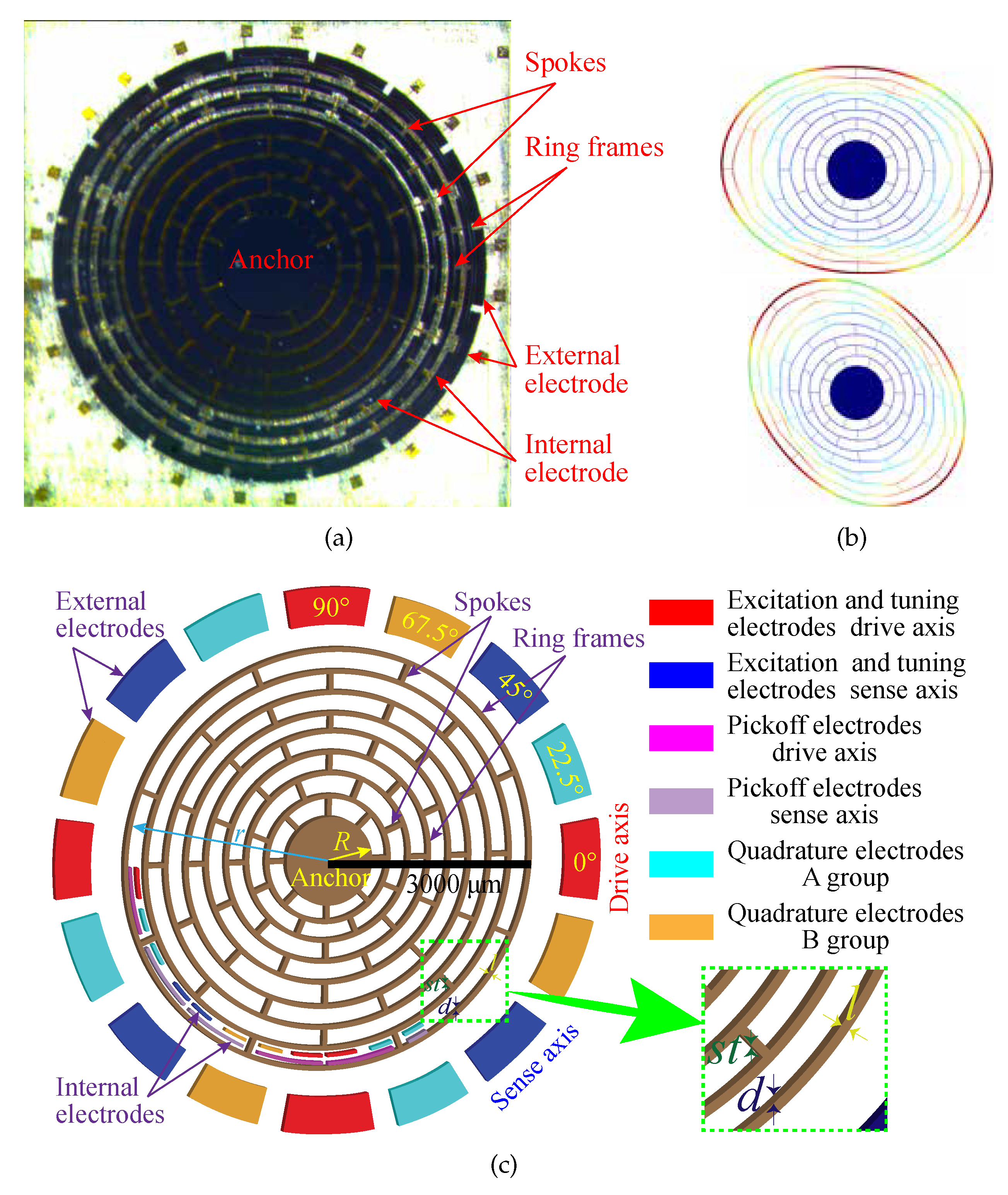
2.1. Basic Structure of DRG
2.2. Dynamic Model of DRG
2.3. Electrostatic Force and Electrostatic Negative Stiffness Effect
3. Automatic Mode-Matching method based on Virtual Coriolis Force
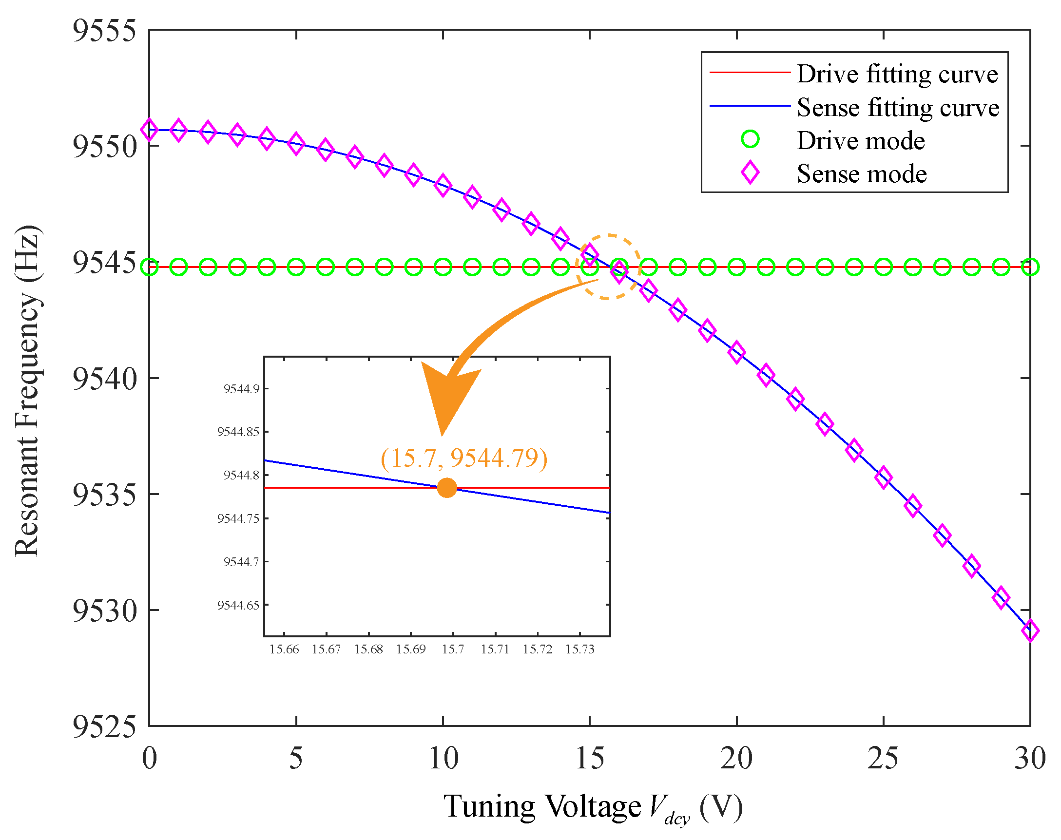
3.1. Electrostatic Stiffness Tuning Theory
3.2. Mode-Matching Control System
3.2.1. System Features in Mode-Matching
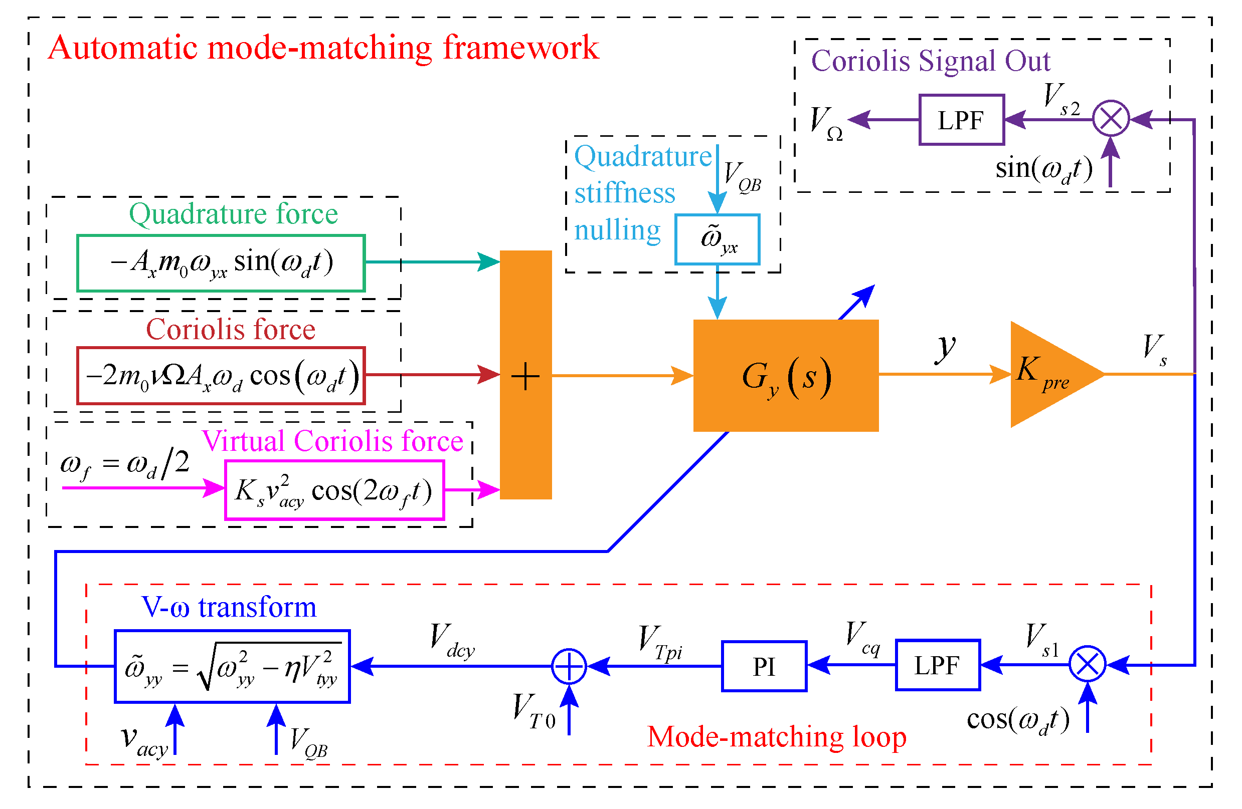
3.2.2. Control System Framework
3.2.3. Analysis of Mode-Matching Loop
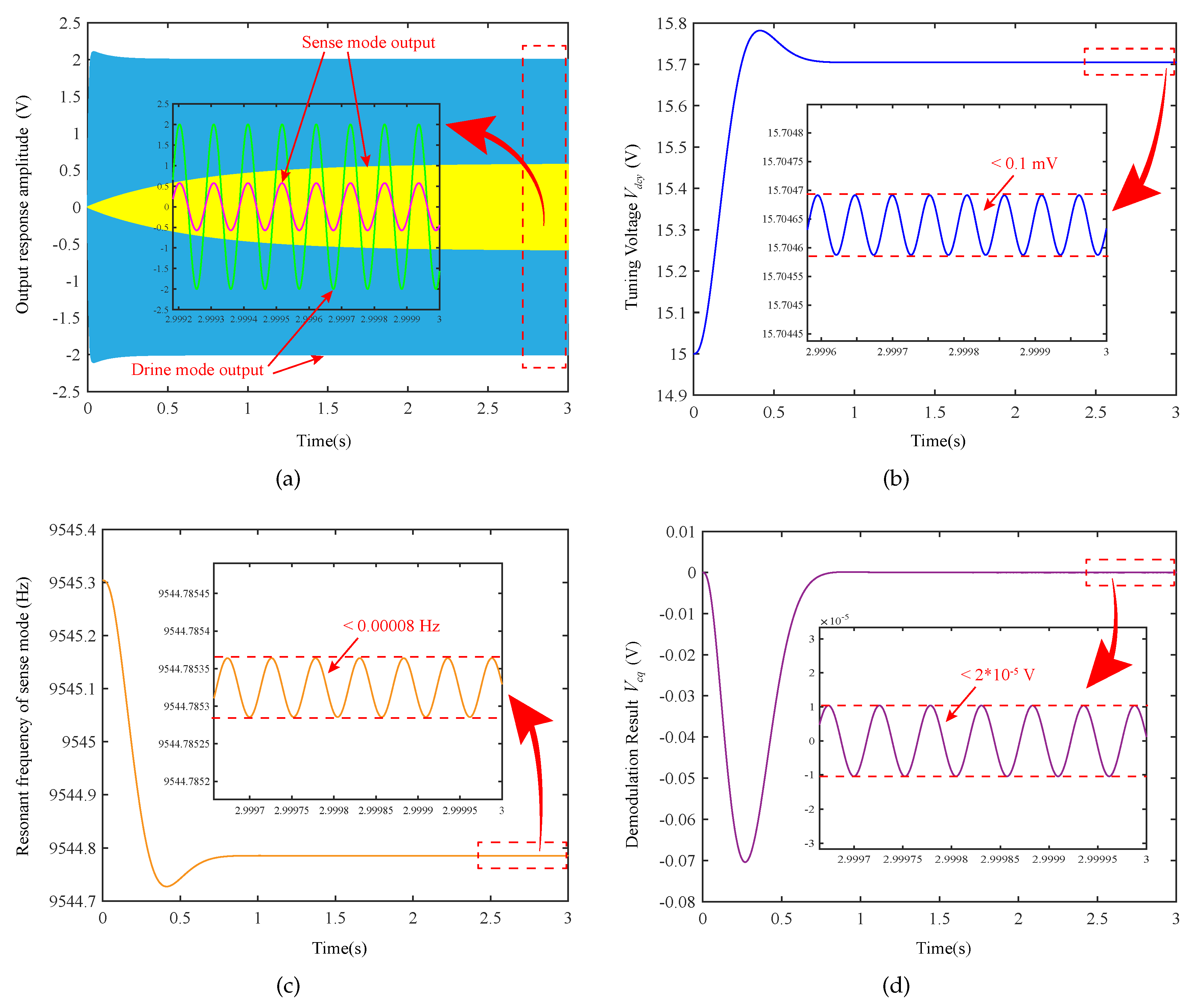
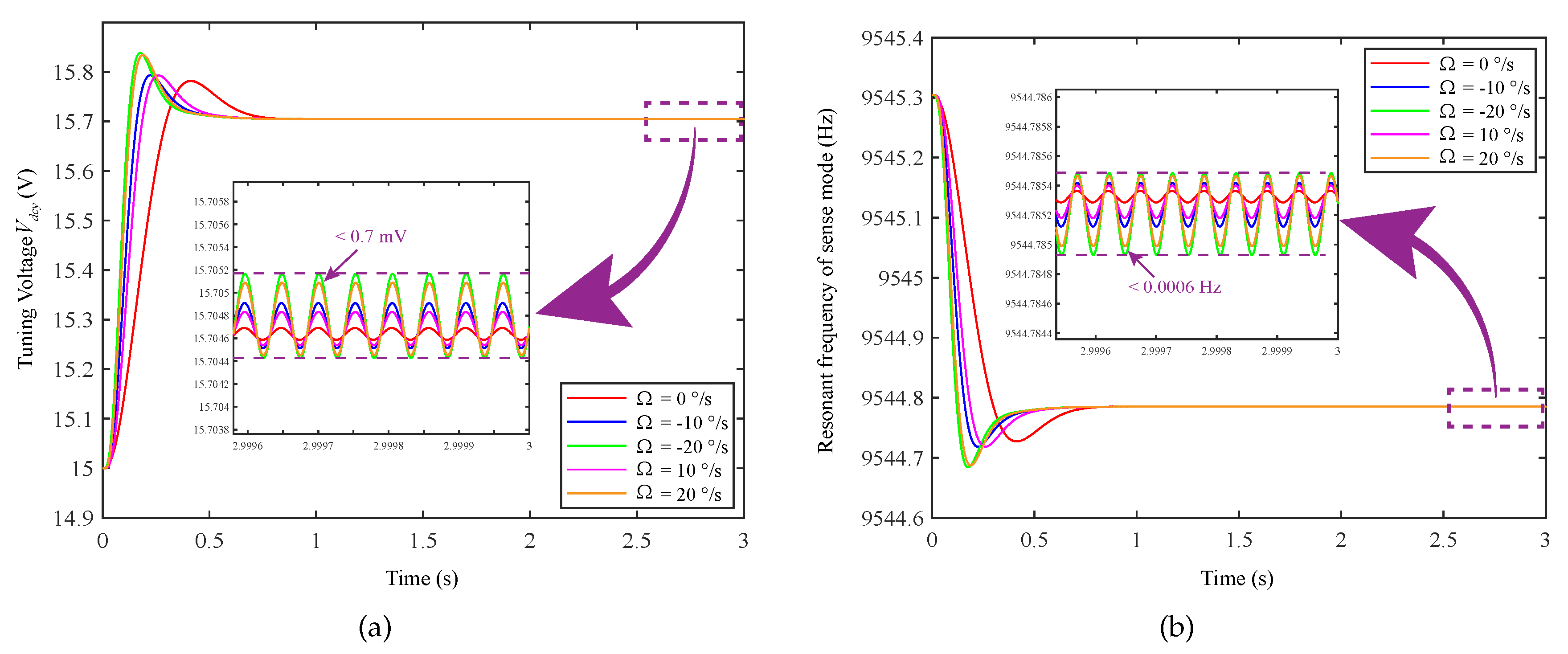
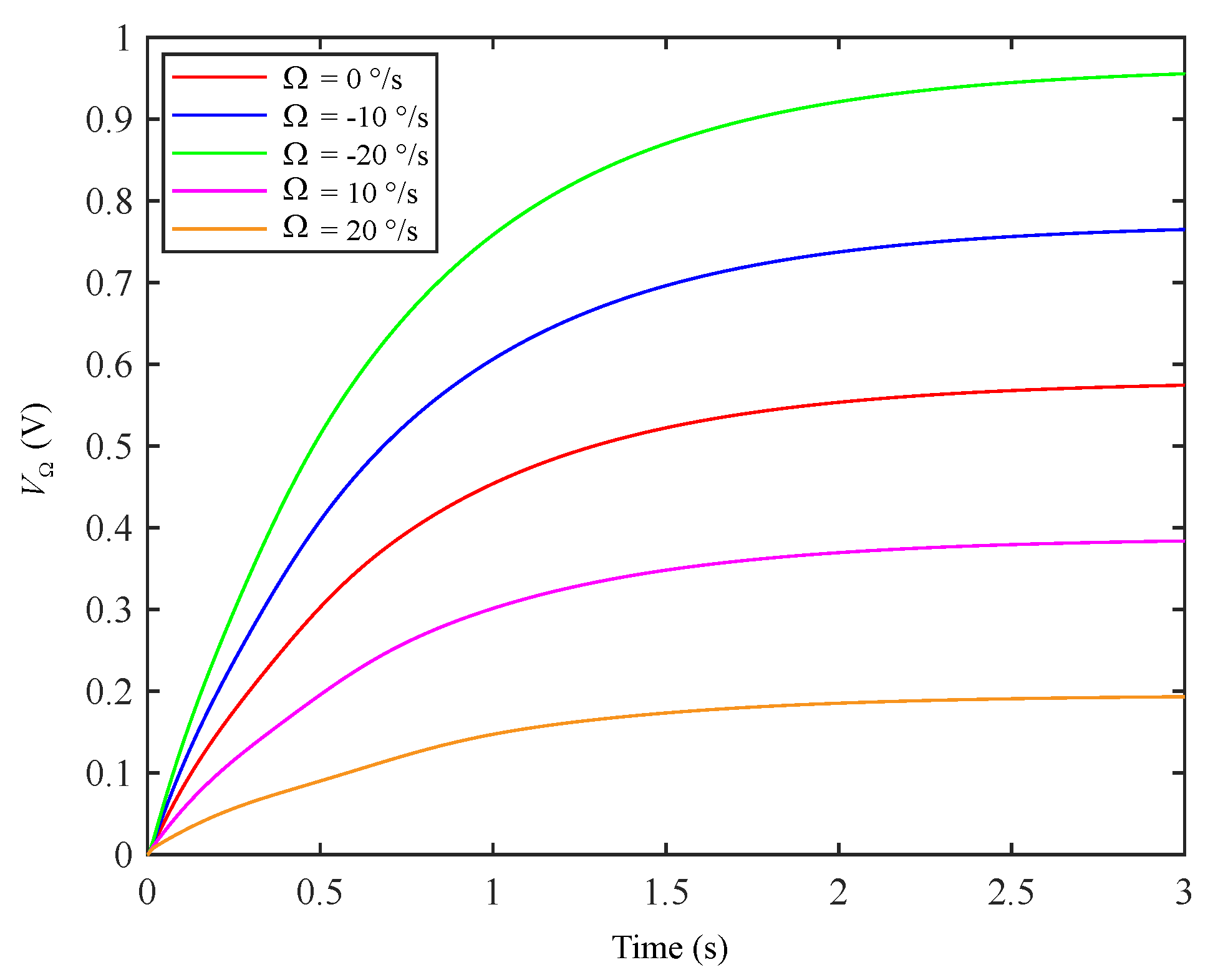
4. Simulation Analysis for Automatic Mode Matching
5. Experimental Analysis Results
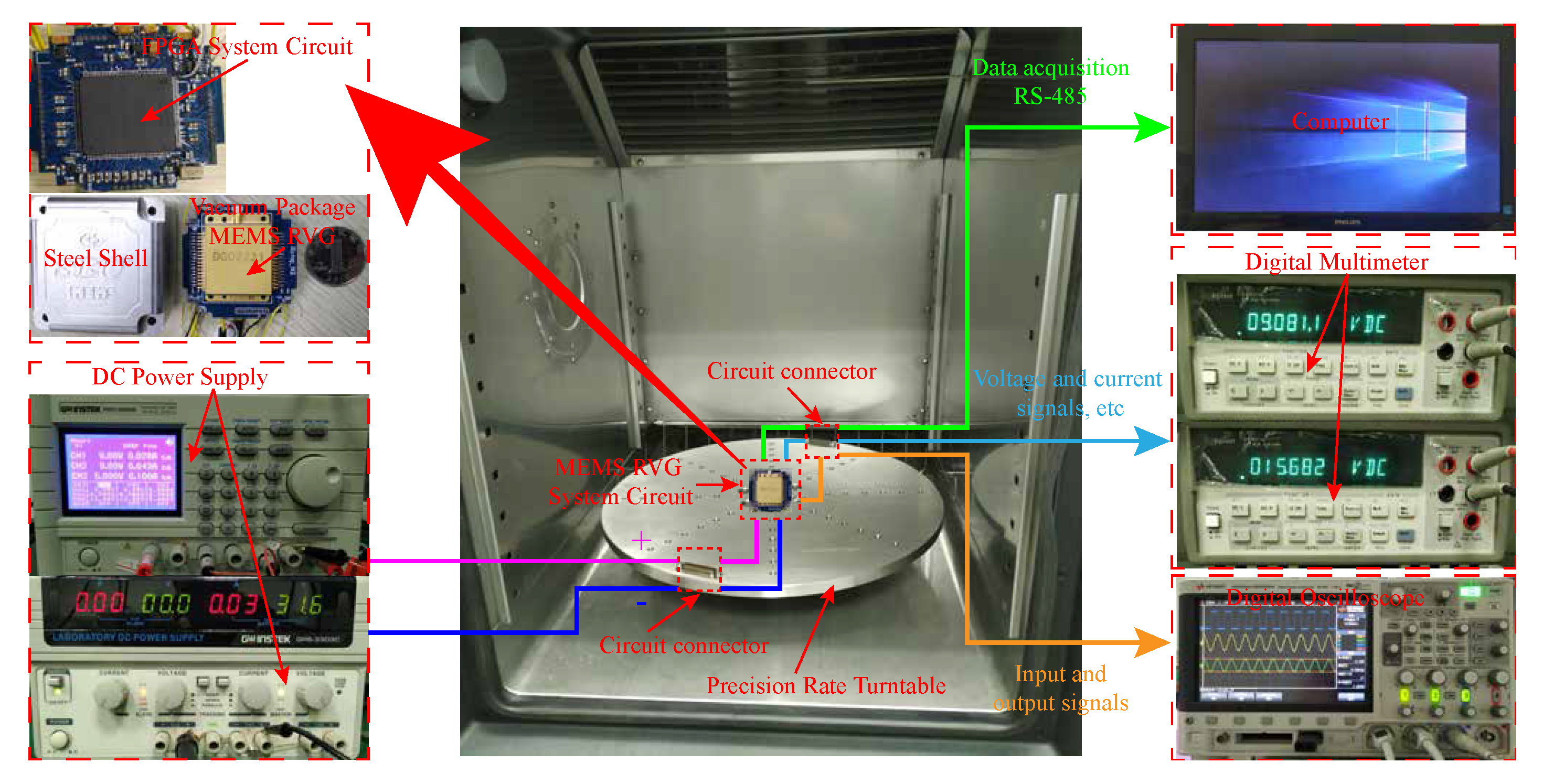
5.1. Experimental Equipment and Circuit
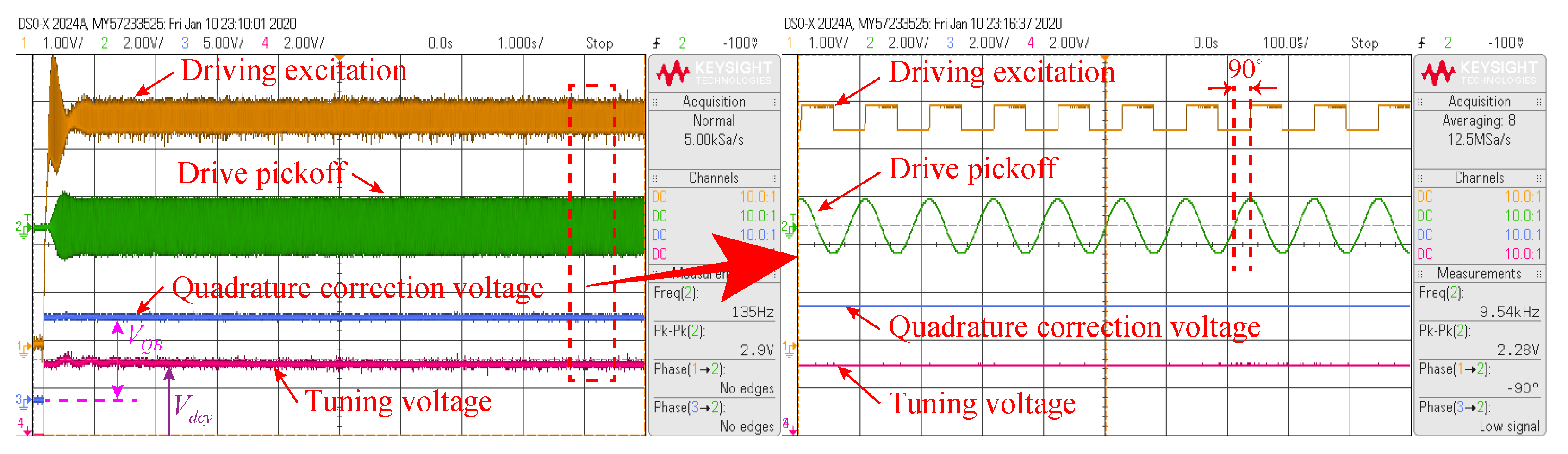
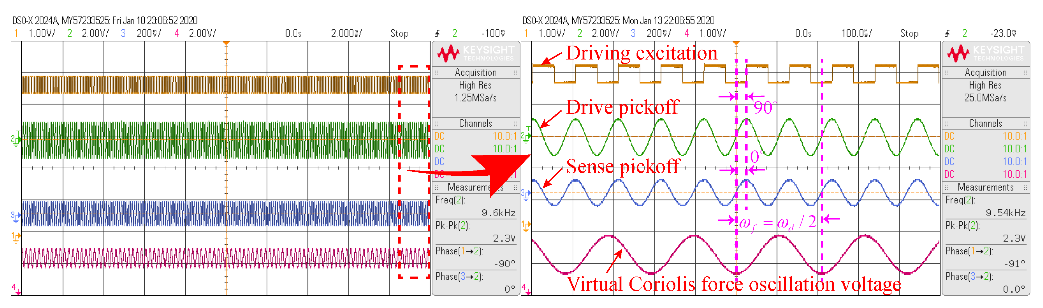
5.2. Mode-Matching Implementation Process
6. Conclusions
Author Contributions
Funding
Conflicts of Interest
References
- Kou, Z.; Liu, J.; Cao, H.; Feng, H.; Ren, J.; Kang, Q.; Shi, Y. Design and fabrication of a novel MEMS vibrating ring gyroscope. In Proceedings of the 2017 IEEE 3rd Information Technology and Mechatronics Engineering Conference (ITOEC), Chongqing, China, 3–5 October 2017; pp. 131–134. [Google Scholar]
- Mittapally, G.K.M.; Dantala, D.; Chhabra, I.; Kishore, P.; Rao, N.V.N.; Das, K.C. Analysis of metallic hemispherical shell vibration modes for coriolis vibratory gyroscope. IOP Conf. Ser. Mater. Sci. Eng. 2018, 383, 012022. [Google Scholar] [CrossRef]
- Xu, Z.; Yi, G.; Er, M.; Huang, C. Effect of Uneven Electrostatic Forces on the Dynamic Characteristics of Capacitive Hemispherical Resonator Gyroscopes. Sensors 2019, 19, 1291. [Google Scholar] [CrossRef] [PubMed]
- Shiari, B.; Nagourney, T.; Darvishian, A.; Yoong Cho, J.; Najafi, K. Numerical prediction of stress evolution during blowtorch reflow of fused silica micro-shell resonators. In Proceedings of the 2016 IEEE International Symposium on Inertial Sensors and Systems, Laguna Beach, CA, USA, 22–25 February 2016; pp. 13–16. [Google Scholar]
- Lynch, D.D. Vibratory Gyro Analysis by the Method of Averaging. In Proceedings of the Proc. 2nd Saint Petersburg Int. Conf. on Gyroscopic Technology and Navigation, Saint Petersburg, Russia, 24–26 May 1995; pp. 26–34. [Google Scholar]
- Lynch, D.D. MRIG frequency mismatch and quadrature control. In Proceedings of the 2014 International Symposium on Inertial Sensors and Systems (ISISS), Laguna Beach, CA, USA, 25–26 February 2014; pp. 1–4. [Google Scholar]
- Chouvion, B.; McWilliam, S.; Popov, A. Effect of nonlinear electrostatic forces on the dynamic behaviour of a capacitive ring-based Coriolis Vibrating Gyroscope under severe shock. Mech. Syst. Signal Process. 2018, 106, 395–412. [Google Scholar] [CrossRef]
- Cao, H.; Liu, Y.; Kou, Z.; Zhang, Y.; Shao, X.; Gao, J.; Huang, K.; Shi, Y.; Tang, J.; Shen, C.; et al. Design, Fabrication and Experiment of Double U-Beam MEMS Vibration Ring Gyroscope. Micromachines 2019, 10, 186. [Google Scholar] [CrossRef] [PubMed]
- Bu, F.; Guo, S.; Cheng, M.; Zheng, F.; Xu, D.; Zhao, H. Effect of circuit phase delay on bias stability of MEMS gyroscope under force rebalance detection and self-compensation method. J. Micromech. Microeng. 2019, 29, 095002. [Google Scholar] [CrossRef]
- Li, Q.; Zhou, X.; Hou, Z.; Zhuo, M.; Xu, Y.; Wu, X. Dynamic Modeling of the Multiring Disk Resonator Gyroscope. Micromachines 2019, 10, 181. [Google Scholar] [CrossRef]
- Fan, B.; Guo, S.; Cheng, M.; Yu, L.; Zhou, M.; Hu, W.; Zheng, F.; Bu, F.; Xu, D. Frequency Symmetry Comparison of Cobweb-Like Disk Resonator Gyroscope with Ring-Like Disk Resonator Gyroscope. IEEE Electron. Device Lett. 2019, 40, 1515–1518. [Google Scholar] [CrossRef]
- Fan, B.; Guo, S.; Cheng, M.; Yu, L.; Zhou, M.; Hu, W.; Chen, Z.; Xu, D. A Novel High-Symmetry Cobweb-Like Disk Resonator Gyroscope. IEEE Sens. J. 2019, 19, 10289–10297. [Google Scholar] [CrossRef]
- Zhou, X.; Xiao, D.; Li, Q.; Hou, Z.; He, K.; Chen, Z.; Wu, Y.; Wu, X. Decaying Time Constant Enhanced MEMS Disk Resonator for High Precision Gyroscopic Application. IEEE/ASME Trans. Mechatron. 2018, 23, 452–458. [Google Scholar] [CrossRef]
- Zhou, X.; Xiao, D.; Hou, Z.; Li, Q.; Wu, Y.; Yu, D.; Li, W.; Wu, X. Thermoelastic quality-factor enhanced disk resonator gyroscope. In Proceedings of the 2017 IEEE 30th International Conference on Micro Electro Mechanical Systems (MEMS), Las Vegas, NV, USA, 22–26 January 2017; pp. 1009–1012. [Google Scholar]
- Zhou, X.; Wu, Y.; Xiao, D.; Hou, Z.; Li, Q.; Yu, D.; Wu, X. An investigation on the ring thickness distribution of disk resonator gyroscope with high mechanical sensitivity. Int. J. Mech. Sci. 2016, 117, 174–181. [Google Scholar] [CrossRef]
- Zhou, X.; Xiao, D.; Hou, Z.; Li, Q.; Wu, Y.; Wu, X. Influences of the Structure Parameters on Sensitivity and Brownian Noise of the Disk Resonator Gyroscope. J. Microelectromech. Syst. 2017, 26, 519–527. [Google Scholar] [CrossRef]
- Lin, C.; Zhao, J.; Yao, Z.; Fan, Q.; Mo, B.; Su, Y. Vibration modeling of disk resonator gyroscope by wave propagation. J. Sound Vib. 2019, 444, 85–107. [Google Scholar] [CrossRef]
- Qin, Z.; Gao, Y.; Jia, J.; Ding, X.; Huang, L.; Li, H. The Effect of the Anisotropy of Single Crystal Silicon on the Frequency Split of Vibrating Ring Gyroscopes. Micromachines 2019, 10, 126. [Google Scholar] [CrossRef] [PubMed]
- Gallacher, B.J.; Hedley, J.; Burdess, J.S.; Harris, A.J.; Rickard, A.; King, D.O. Electrostatic correction of structural imperfections present in a microring gyroscope. J. Microelectromech. Syst. 2005, 14, 221–234. [Google Scholar] [CrossRef]
- Hu, Z.X.; Gallacher, B.J.; Burdess, J.S.; Bowles, S.R.; Grigg, H.T.D. A systematic approach for precision electrostatic mode tuning of a MEMS gyroscope. J. Micromech. Microeng. 2014, 24, 125003. [Google Scholar] [CrossRef]
- Efimovskaya, A.; Wang, D.; Lin, Y.W.; Shkel, A.M. Electrostatic compensation of structural imperfections in dynamically amplified dual-mass gyroscope. Sens. Actuators A Phys. 2018, 275, 99–108. [Google Scholar] [CrossRef]
- Lu, K.; Shi, Y.; Xiao, D.; Hou, Z.; Li, W.; Wu, X.; Wu, Y. Investigation on precise frequency trimming of a micro shell resonator with T-shape masses using low-power femtosecond laser ablation. In Proceedings of the 2018 IEEE International Symposium on Inertial Sensors and Systems (INERTIAL), Moltrasio, Italy, 26–29 March 2018; pp. 1–4. [Google Scholar]
- Lu, K.; Xi, X.; Li, W.; Shi, Y.; Hou, Z.; Zhuo, M.; Wu, X.; Wu, Y.; Xiao, D. Research on precise mechanical trimming of a micro shell resonator with T-shape masses using femtosecond laser ablation. Sens. Actuators A Phys. 2019, 290, 228–238. [Google Scholar] [CrossRef]
- Cheng, M.; Guo, S.; Fan, B.; Wan, Q.; Wen, Z.; Xu, D. Automatic Mode-Matching and Scale Factor Adjustable Detection System for Force to Rebalance Control of Cobweb-Like Gyroscopes. In Proceedings of the 2018 IEEE SENSORS, New Delhi, India, 28–31 October 2018; pp. 1–4. [Google Scholar]
- Hodjat-Shamami, M.; Norouzpour-Shirazi, A.; Tabrizian, R.; Ayazi, F. A dynamically mode-matched piezoelectrically transduced high-frequency flexural disk gyroscope. In Proceedings of the 2015 28th IEEE International Conference on Micro Electro Mechanical Systems (MEMS), Estoril, Portugal, 18–22 January 2015; pp. 789–792. [Google Scholar]
- Guan, Y.; Gao, S.; Liu, H.; Jin, L.; Zhang, Y. Vibration Sensitivity Reduction of Micromachined Tuning Fork Gyroscopes through Stiffness Match Method with Negative Electrostatic Spring Effect. Sensors 2016, 16, 1146. [Google Scholar] [CrossRef]
- Sung, S.; Sung, W.; Kim, C.; Yun, S.; Lee, Y.J. On the Mode-Matched Control of MEMS Vibratory Gyroscope via Phase-Domain Analysis and Design. IEEE/ASME Trans. Mechatron. 2009, 14, 446–455. [Google Scholar] [CrossRef]
- Antonello, R.; Oboe, R.; Prandi, L.; Biganzoli, F. Automatic Mode Matching in MEMS Vibrating Gyroscopes Using Extremum-Seeking Control. IEEE Trans. Ind. Electron. 2009, 56, 3880–3891. [Google Scholar] [CrossRef]
- Xu, L.; Li, H.; Yang, C.; Huang, L. Comparison of Three Automatic Mode-Matching Methods for Silicon Micro-Gyroscopes Based on Phase Characteristic. IEEE Sens. J. 2016, 16, 610–619. [Google Scholar] [CrossRef]
- Bu, F.; Xu, D.; Zhao, H.; Fan, B.; Cheng, M. MEMS Gyroscope Automatic Real-Time Mode-Matching Method Based on Phase-Shifted 45° Additional Force Demodulation. Sensors 2018, 18, 3001. [Google Scholar] [CrossRef]
- Hu, Z.; Gallacher, B. A mode-matched force-rebalance control for a MEMS vibratory gyroscope. Sens. Actuators A Phys. 2018, 273, 1–11. [Google Scholar] [CrossRef]
- Li, C.; Wen, H.; Wisher, S.; Norouzpour-Shirazi, A.; Lei, J.; Chen, H.; Ayazi, F. An FPGA-Based Interface System for High Frequency Bulk-Acoustic-Wave (BAW) Micro-Gyroscopes with In-Run Automatic Mode-Matching. IEEE Trans. Instrum. Meas. 2019, 1–10. [Google Scholar] [CrossRef]
- Xiao, D.; Yu, D.; Zhou, X.; Hou, Z.; He, H.; Wu, X. Frequency Tuning of a Disk Resonator Gyroscope via Stiffness Perturbation. IEEE Sens. J. 2017, 17, 4725–4734. [Google Scholar] [CrossRef]
- Peng, Y.; Zhao, H.; Bu, F.; Yu, L.; Xu, D.; Guo, S. An Automatically Mode-Matched MEMS Gyroscope Based on Phase Characteristics. In Proceedings of the 2019 IEEE 3rd Information Technology, Networking, Electronic and Automation Control Conference (ITNEC), Chengdu, China, 15–17 March 2019; pp. 2466–2470. [Google Scholar]
- Sharma, A.; Zaman, M.F.; Ayazi, F. A Sub-0.2°/ hr Bias Drift Micromechanical Silicon Gyroscope With Automatic CMOS Mode-Matching. IEEE J. Solid-State Circuits 2009, 44, 1593–1608. [Google Scholar] [CrossRef]
- Sonmezoglu, S.; Alper, S.E.; Akin, T. An automatically mode-matched MEMS gyroscope with 50 Hz bandwidth. In Proceedings of the 2012 IEEE 25th International Conference on Micro Electro Mechanical Systems (MEMS), Paris, France, 29 January–2 February 2012; pp. 523–526. [Google Scholar]
- Sonmezoglu, S.; Alper, S.E.; Akin, T. An Automatically Mode-Matched MEMS Gyroscope With Wide and Tunable Bandwidth. J. Microelectromech. Syst. 2014, 23, 284–297. [Google Scholar] [CrossRef]
- Cao, Y.; Torres, D.; Wang, T.; Tan, X.; Sepúlveda, N. Enabling tunable micromechanical bandpass filters through phase-change materials. Smart Mater. Struct. 2017, 26, 085032. [Google Scholar] [CrossRef]
- Cao, Y.; Sepúlveda, N. Interface Stress for Bidirectional Frequency Tuning of Prebuckled Vanadium Dioxide MEMS Resonators. Adv. Mater. Interfaces 2019, 6, 1900887. [Google Scholar] [CrossRef]
- Hu, Z.; Gallacher, B. Control and damping imperfection compensation for a rate integrating MEMS gyroscope. In Proceedings of the 2015 DGON Inertial Sensors and Systems Symposium (ISS), Karlsruhe, Germany, 22–23 September 2015; pp. 1–15. [Google Scholar]
- Ding, X.; Jia, J.; Qin, Z.; Ruan, Z.; Zhao, L.; Li, H. A Lumped Mass Model for Circular Micro-Resonators in Coriolis Vibratory Gyroscopes. Micromachines 2019, 10, 378. [Google Scholar] [CrossRef]
- Zhao, H.; Ren, S. Working Principle and Error Analysis for Hemispherical Resonator Gyro under Force-rebalance Mode. J. Harbin Institute Technol. 2013, 20, 75–80. [Google Scholar]
- Cetin, H.; Yaralioglu, G.G. Analysis of Vibratory Gyroscopes: Drive and Sense Mode Resonance Shift by Coriolis Force. IEEE Sens. J. 2017, 17, 347–358. [Google Scholar] [CrossRef]
- Zhongxu Hu, B.J.G. Precision mode tuning towards a low angle drift MEMS rate integrating gyroscope. Mechatronics 2018, 56, 306–317. [Google Scholar]
- Ding, X.; Li, H.; Zhu, K.; Zhang, Y. A Force Rebalanced Micro-Gyroscope Driven by Voltages Oscillating at Half of Structure’s Resonant Frequency. IEEE Sens. J. 2016, 16, 8897–8907. [Google Scholar] [CrossRef]


| Parameter | Value | Unit |
|---|---|---|
| Radius of disk r | 3000 | m |
| Thickness of nested ring d | 120 | m |
| Width of nested ring l | 80 | m |
| Single electrode width | 20 | |
| Initial electrode gap | 5.2 | m |
| Radius of anchor R | 750 | m |
| Thickness of spoke | 8 | m |
| Parameter | Value | Unit |
|---|---|---|
| Drive mode resonance frequency | 9546.06 | Hz |
| Driving mode quality factor | 19,133 | |
| Sense mode resonance frequency | 9552.33 | Hz |
| Sense mode quality factor | 19,265 | |
| Quadrature stiffness correction voltage | 9.08 | V |
| Mode matching loop preset voltage | 15.0 | V |
| Vacuum permittivity | F/m | |
| Mode effective mass | kg |
| Parameter | Mode Mismatch | Mode Matching |
|---|---|---|
| Frequency Split (Hz) | 6.2700 | <0.1000 |
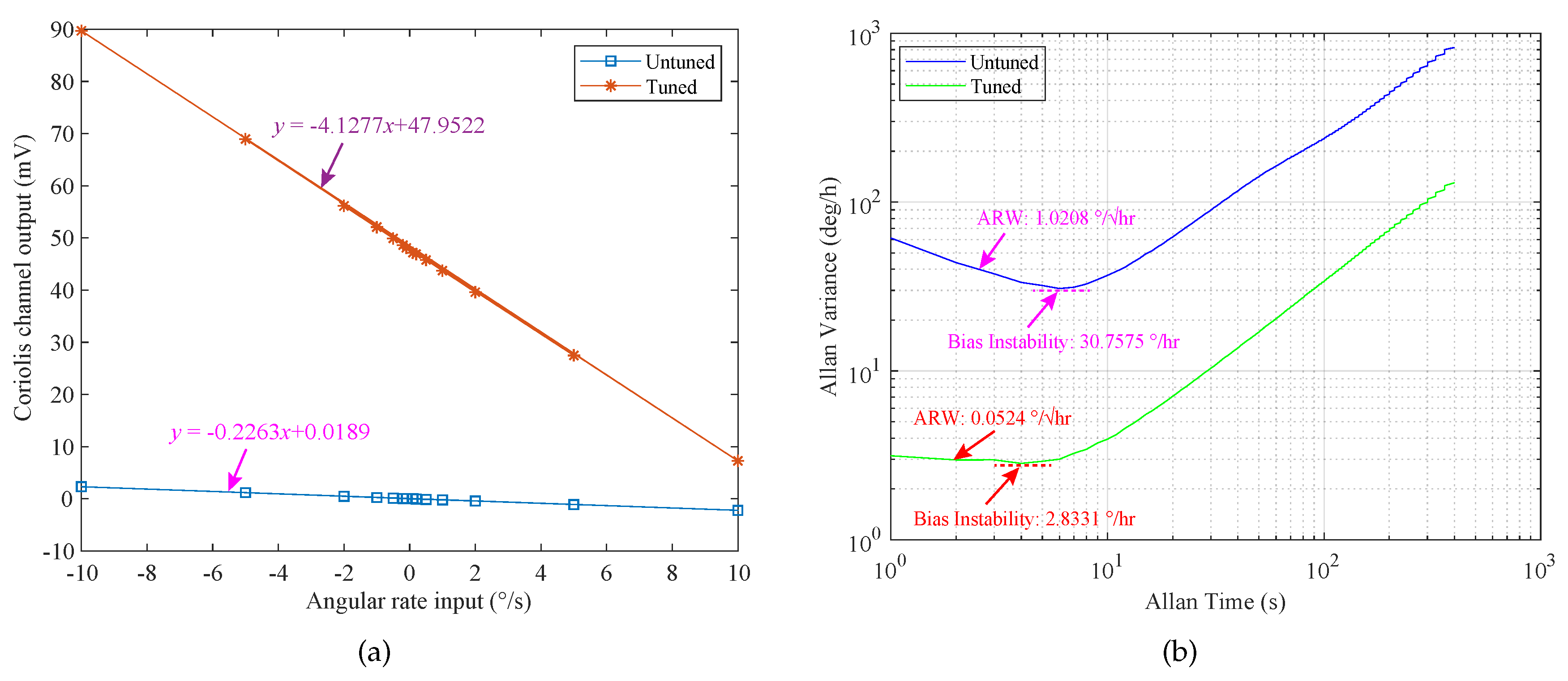
| Scale Factor (mV//s) | 0.2263 | 4.1277 |
| Measurable Range (/s) | ||
| Bias Instability (/h) | 30.7575 | 2.8331 |
| ARW () | 1.0208 | 0.0524 |
© 2020 by the authors. Licensee MDPI, Basel, Switzerland. This article is an open access article distributed under the terms and conditions of the Creative Commons Attribution (CC BY) license (http://creativecommons.org/licenses/by/4.0/).
Share and Cite
Ruan, Z.; Ding, X.; Qin, Z.; Jia, J.; Li, H. Automatic Mode-Matching Method for MEMS Disk Resonator Gyroscopes Based on Virtual Coriolis Force. Micromachines 2020, 11, 210. https://doi.org/10.3390/mi11020210
Ruan Z, Ding X, Qin Z, Jia J, Li H. Automatic Mode-Matching Method for MEMS Disk Resonator Gyroscopes Based on Virtual Coriolis Force. Micromachines. 2020; 11(2):210. https://doi.org/10.3390/mi11020210
Chicago/Turabian StyleRuan, Zhihu, Xukai Ding, Zhengcheng Qin, Jia Jia, and Hongsheng Li. 2020. "Automatic Mode-Matching Method for MEMS Disk Resonator Gyroscopes Based on Virtual Coriolis Force" Micromachines 11, no. 2: 210. https://doi.org/10.3390/mi11020210
APA StyleRuan, Z., Ding, X., Qin, Z., Jia, J., & Li, H. (2020). Automatic Mode-Matching Method for MEMS Disk Resonator Gyroscopes Based on Virtual Coriolis Force. Micromachines, 11(2), 210. https://doi.org/10.3390/mi11020210