Non-Diffractive Bessel Beams for Ultrafast Laser Scanning Platform and Proof-Of-Concept Side-Wall Polishing of Additively Manufactured Parts


 ,
, 

 and
and 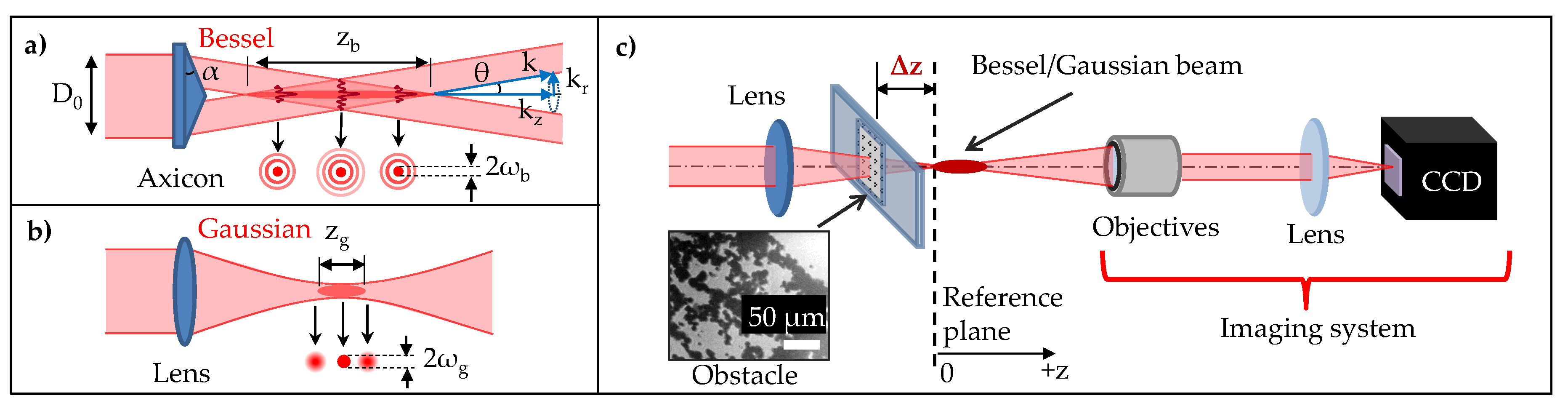
Abstract
1. Introduction
2. Results and Discussion
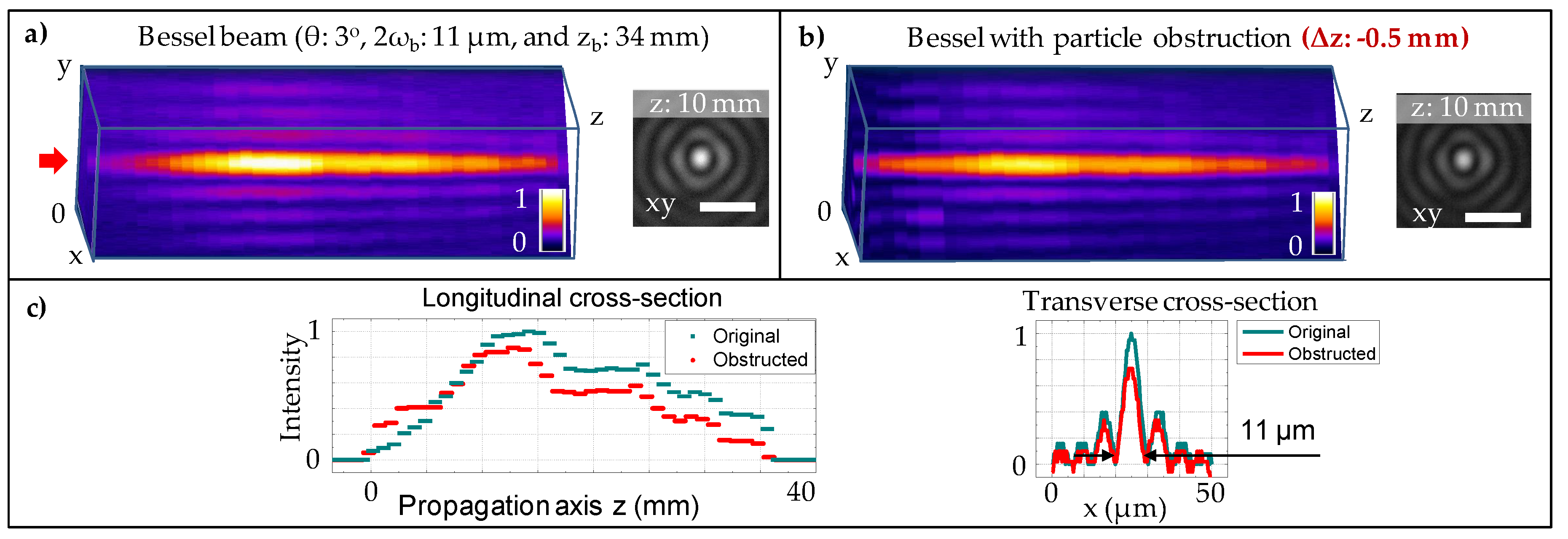
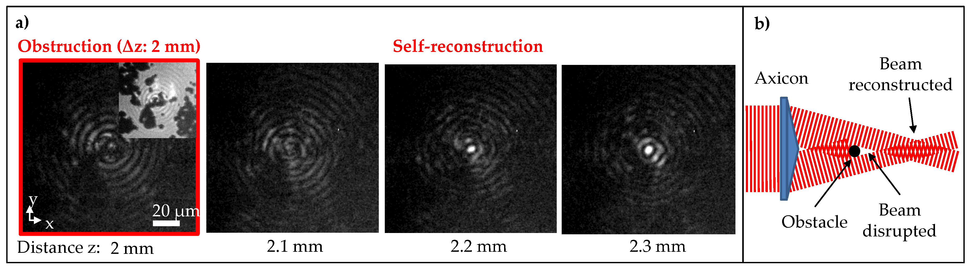
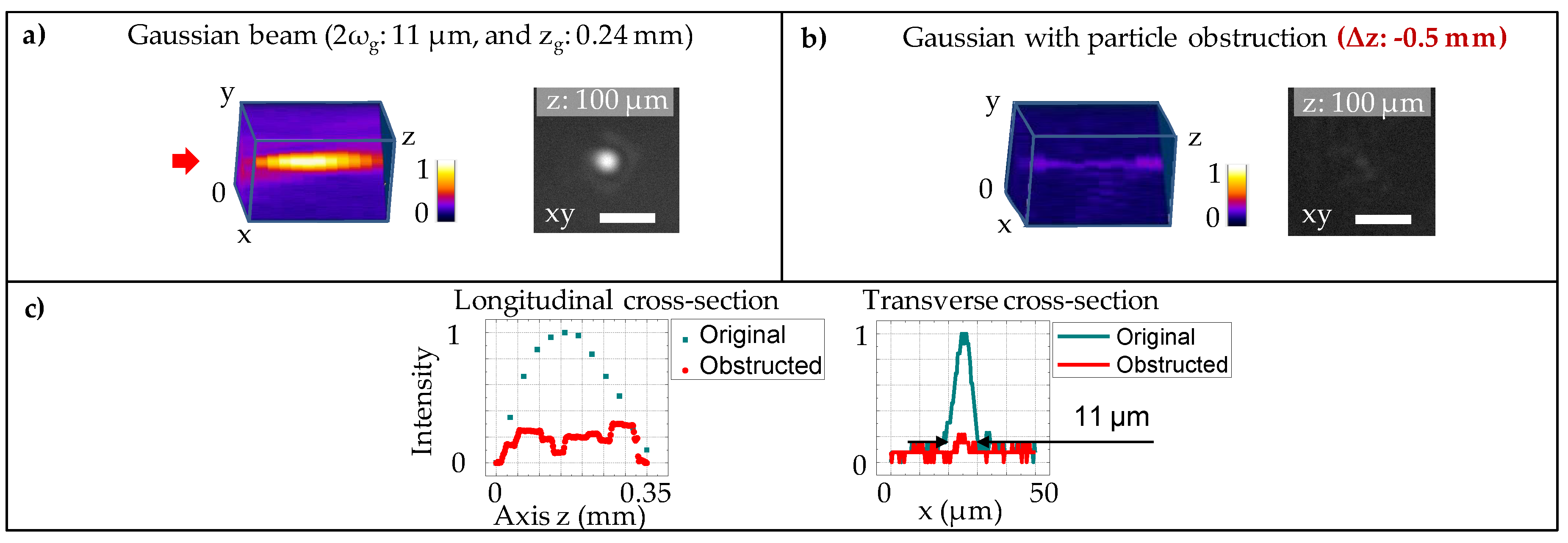
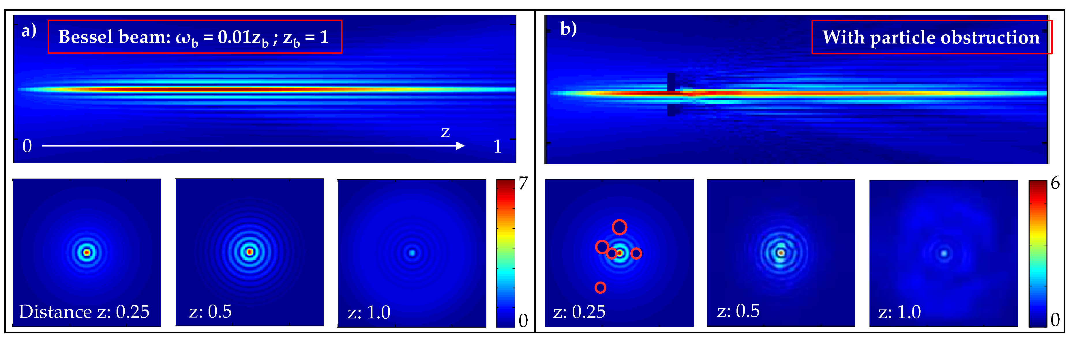
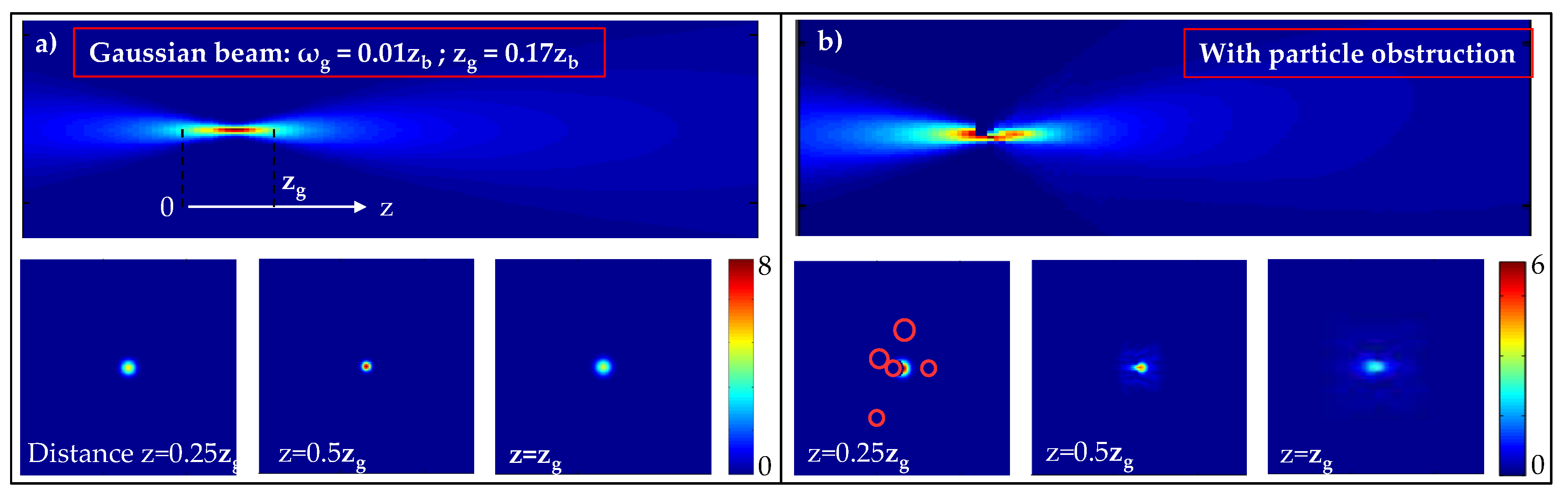
2.1. Bessel Beam and Its Self-Healing Property under Particle Obstruction
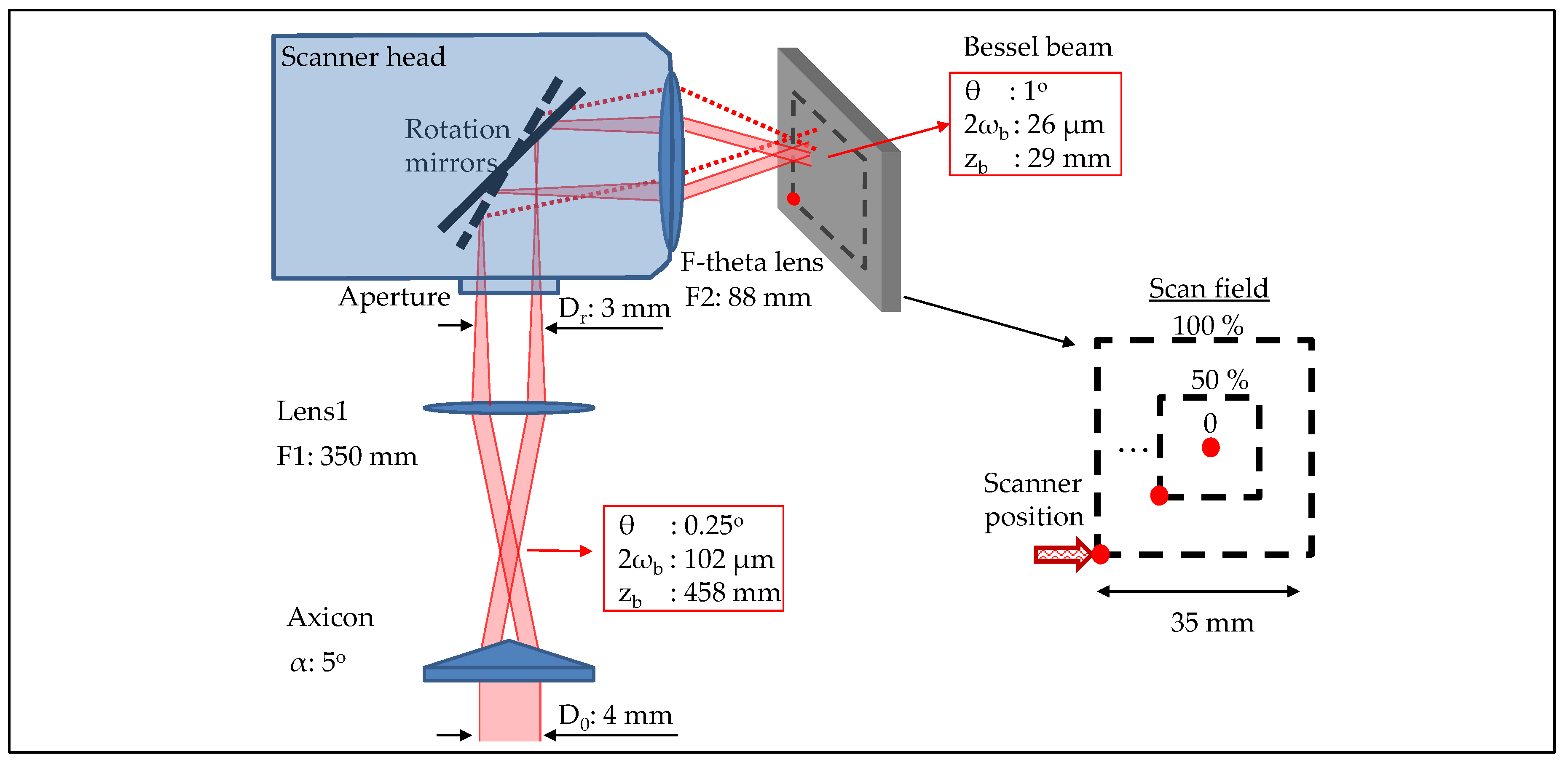
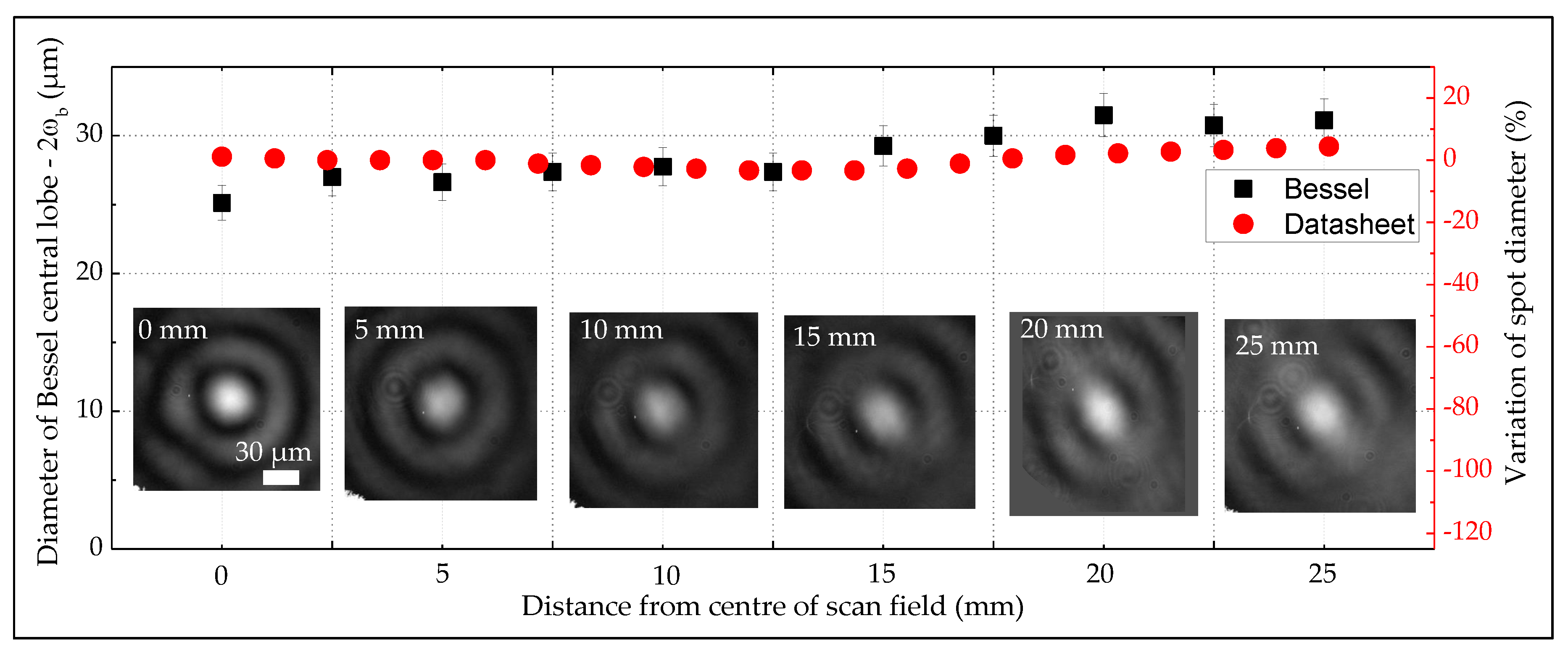
2.2. Bessel Beam Scanning Platform
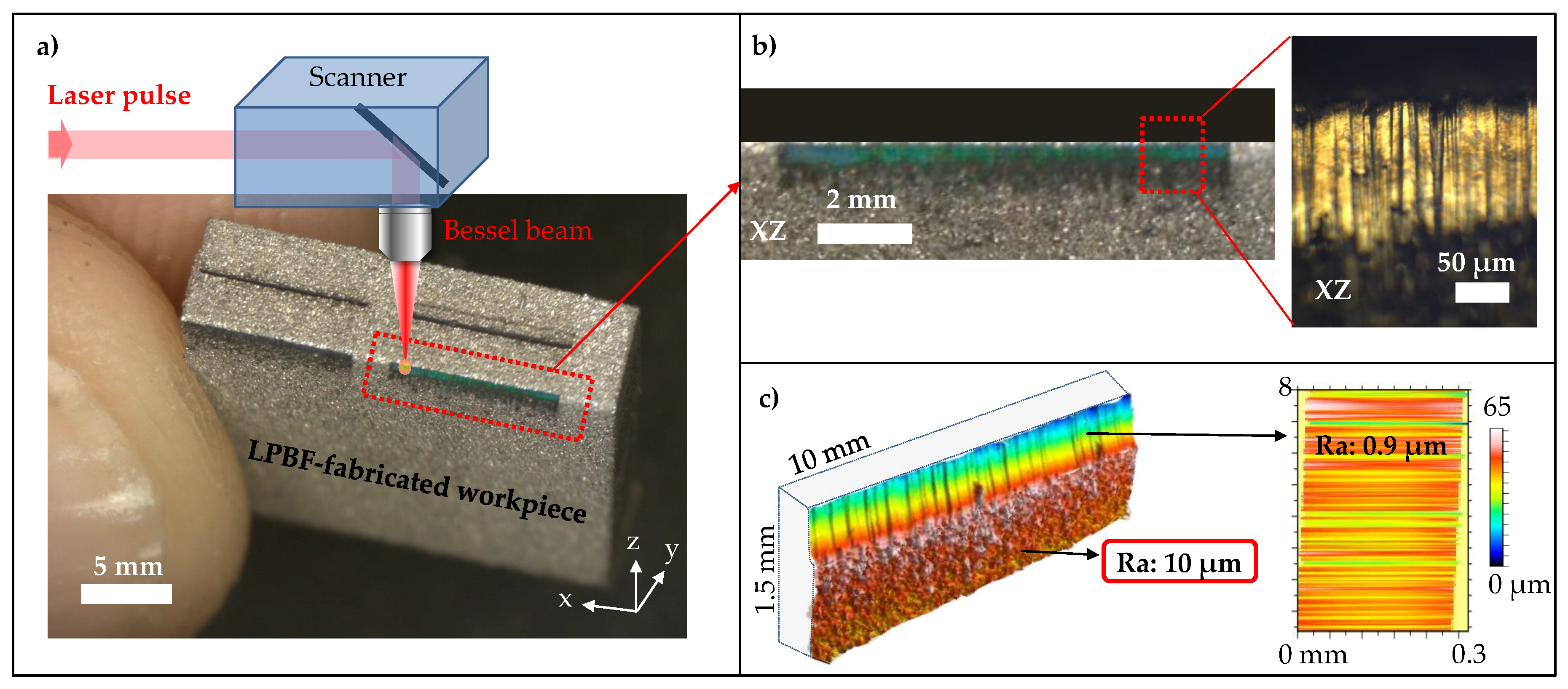
2.3. Side-Wall Polishing with Bessel Beam
3. Materials and Methods
4. Conclusions
Author Contributions
Funding
Acknowledgments
Conflicts of Interest
Abbreviations
| AM | Additive manufacturing |
| 3D | 3-dimensional |
| LPBF | Laser powder bed fusion |
| SLM | Selective laser melting |
| CNC | Computer numerical control |
| CW | Continuous-wave |
| BG | Bessel-Gaussian |
Appendix A


References
- Gasser, A.; Backes, G.; Kelbassa, I.; Weisheit, A.; Wissenbach, K. Laser Additive Manufacturing: Laser Metal Deposition (LMD) and Selective Laser Melting (SLM) in Turbo-Engine Applications. Laser Tech. J. 2010, 7, 58–63. [Google Scholar] [CrossRef]
- Gibson, I.; Rosen, D.W.; Stucker, B. Additive Manufacturing Technologies; Springer: Boston, MA, USA, 2010. [Google Scholar]
- Herzog, D.; Seyda, V.; Wycisk, E.; Emmelmann, C. Additive manufacturing of metals. Acta Mater. 2016, 117, 371–392. [Google Scholar] [CrossRef]
- Frazier, W.E. Metal Additive Manufacturing: A Review. J. Mater. Eng. Perform. 2014, 23, 1917–1928. [Google Scholar] [CrossRef]
- Suryawanshi, J.; Prashanth, K.G.; Ramamurty, U. Mechanical behavior of selective laser melted 316L stainless steel. Mater. Sci. Eng. A 2017, 696, 113–121. [Google Scholar] [CrossRef]
- Prashanth, K.G.; Scudino, S.; Klauss, H.J.; Surreddi, K.B.; Löber, L.; Wang, Z.; Chaubey, A.K.; Kühn, U.; Eckert, J. Microstructure and mechanical properties of Al–12Si produced by selective laser melting: Effect of heat treatment. Mater. Sci. Eng. A 2014, 590, 153–160. [Google Scholar] [CrossRef]
- Schwab, H.; Prashanth, K.; Löber, L.; Kühn, U.; Eckert, J. Selective Laser Melting of Ti-45Nb Alloy. Metals 2015, 5, 686–694. [Google Scholar] [CrossRef]
- Scudino, S.; Unterdörfer, C.; Prashanth, K.G.; Attar, H.; Ellendt, N.; Uhlenwinkel, V.; Eckert, J. Additive manufacturing of Cu–10Sn bronze. Mater. Lett. 2015, 156, 202–204. [Google Scholar] [CrossRef]
- Ren, D.C.; Zhang, H.B.; Liu, Y.J.; Li, S.J.; Jin, W.; Yang, R.; Zhang, L.C. Microstructure and properties of equiatomic Ti–Ni alloy fabricated by selective laser melting. Mater. Sci. Eng. A 2020, 771, 138586. [Google Scholar] [CrossRef]
- Tonelli, L.; Fortunato, A.; Ceschini, L. CoCr alloy processed by Selective Laser Melting (SLM): Effect of Laser Energy Density on microstructure, surface morphology, and hardness. J. Manuf. Process. 2020, 52, 106–119. [Google Scholar] [CrossRef]
- Townsend, A.; Senin, N.; Blunt, L.; Leach, R.K.; Taylor, J.S. Surface texture metrology for metal additive manufacturing: A review. Precis. Eng. 2016, 46, 34–47. [Google Scholar] [CrossRef]
- Yasa, E.; Deckers, J.; Kruth, J.P. The investigation of the influence of laser re-melting on density, surface quality and microstructure of selective laser melting parts. Rapid Prototyp. J. 2011, 17, 312–327. [Google Scholar] [CrossRef]
- Kumbhar, N.N.; Mulay, A.V. Post Processing Methods used to Improve Surface Finish of Products which are Manufactured by Additive Manufacturing Technologies: A Review. J. Inst. Eng. India Ser. C 2018, 99, 481–487. [Google Scholar] [CrossRef]
- de Formanoir, C.; Suard, M.; Dendievel, R.; Martin, G.; Godet, S. Improving the mechanical efficiency of electron beam melted titanium lattice structures by chemical etching. Addit. Manuf. 2016, 11, 71–76. [Google Scholar] [CrossRef]
- Gora, W.S.; Tian, Y.; Cabo, A.P.; Ardron, M.; Maier, R.R.; Prangnell, P.; Weston, N.J.; Hand, D.P. Enhancing Surface Finish of Additively Manufactured Titanium and Cobalt Chrome Elements Using Laser Based Finishing. Phys. Procedia 2016, 83, 258–263. [Google Scholar] [CrossRef]
- Baubeau, E.; Missemer, F.; Bertrand, F. System and Method for Additively Manufacturing by Laser Melting of a Powder Bed. U.S. Patent US20180272473A1, 22 March 2018. [Google Scholar]
- Ghosh, A.; Wang, X.; Kietzig, A.-M.; Brochu, M. Layer-by-layer combination of laser powder bed fusion (LPBF) and femtosecond laser surface machining of fabricated stainless steel components. J. Manuf. Process. 2018, 35, 327–336. [Google Scholar] [CrossRef]
- Dubey, A.K.; Yadava, V. Laser beam machining—A review. Int. J. Mach. Tools Manuf. 2008, 48, 609–628. [Google Scholar] [CrossRef]
- Chicbkov, B.N.; Momma, C.; Nolte, S.; von Alvensleben, F.; Tünnermann, A. Femtosecond, picosecond and nanosecond laser ablation of solids. Appl. Phys. A 1996, 63, 109–115. [Google Scholar] [CrossRef]
- Lopez, J.; Faucon, M.; Devillard, R.; Zaouter, Y.; Honninger, C.; Mottay, E.; Kling, R. Parameters of Influence in Surface Ablation and Texturing of Metals Using High-power. J. Laser Micro Nanoeng. 2015, 10, 1–10. [Google Scholar] [CrossRef]
- Stoian, R.; Colombier, J.P.; Mauclair, C.; Cheng, G.; Bhuyan, M.K.; Velpula, P.K.; Srisungsitthisunti, P. Spatial and temporal laser pulse design for material processing on ultrafast scales. Appl. Phys. A 2014, 114, 119–127. [Google Scholar] [CrossRef]
- Mishchik, K.; d’Amico, C.; Velpula, P.K.; Mauclair, C.; Boukenter, A.; Ouerdane, Y.; Stoian, R. Ultrafast laser induced electronic and structural modifications in bulk fused silica. J. Appl. Phys. 2013, 114, 133502. [Google Scholar] [CrossRef]
- Nolte, S.; Momma, C.; Jacobs, H.; Chichkov, B.N.; Wellegehausen, B.; Welling, H. Ablation of metals by ultrashort laser pulses. J. Opt. Soc. Am. B 1997, 14, 2716–2722. [Google Scholar] [CrossRef]
- Neuenschwander, B.; Jaeggi, B.; Schmid, M. From fs to Sub-ns: Dependence of the Material Removal Rate on the Pulse Duration for Metals. Phys. Procedia 2013, 41, 794–801. [Google Scholar] [CrossRef]
- Leitz, K.-H.; Redlingshöfer, B.; Reg, Y.; Otto, A.; Schmidt, M. Metal Ablation with Short and Ultrashort Laser Pulses. Phys. Procedia 2011, 12, 230–238. [Google Scholar] [CrossRef]
- Dausinger, F.; Hugel, H.; Konov, V.I. Micromachining with ultrashort laser pulses: From basic understanding to technical applications. In Proceedings of the ALT’02 International Conference on Advanced Laser Technologies, Silsoe, UK, 14 November 2003; Weber, H.P., Konov, V.I., Graf, T., Eds.; International Society for Optics and Photonics: London, UK, 2003; pp. 106–115. [Google Scholar]
- Neuenschwander, B.; Jaeggi, B.; Schmid, M.; Hennig, G. Surface Structuring with Ultra-short Laser Pulses: Basics, Limitations and Needs for High Throughput. Phys. Procedia 2014, 56, 1047–1058. [Google Scholar] [CrossRef]
- Stoian, R.; Bhuyan, M.K.; Zhang, G.; Cheng, G.; Meyer, R.; Courvoisier, F. Ultrafast Bessel beams: Advanced tools for laser materials processing. Adv. Opt. Technol. 2018, 7, 165–174. [Google Scholar] [CrossRef]
- Lamperti, M.; Jukna, V.; Jedrkiewicz, O.; Di Trapani, P.; Stoian, R.; Itina, T.E.; Xie, C.; Courvoisier, F.; Couairon, A. Invited Article: Filamentary deposition of laser energy in glasses with Bessel beams. APL Photonics 2018, 3, 120805. [Google Scholar] [CrossRef]
- Courvoisier, F.; Stoian, R.; Couairon, A. [INVITED] Ultrafast laser micro- and nano-processing with nondiffracting and curved beams. Opt. Laser Technol. 2016, 80, 125–137. [Google Scholar] [CrossRef]
- Arnold, C.L.; Akturk, S.; Mysyrowicz, A.; Jukna, V.; Couairon, A.; Itina, T.; Stoian, R.; Xie, C.; Dudley, J.M.; Courvoisier, F.; et al. Nonlinear Bessel vortex beams for applications. J. Phys. B At. Mol. Opt. Phys. 2015, 48, 094006. [Google Scholar] [CrossRef]
- Velpula, P.K.; Bhuyan, M.K.; Mauclair, C.; Colombier, J.-P.; Stoian, R. Role of free carriers excited by ultrafast Bessel beams for submicron structuring applications. Opt. Eng. 2014, 53, 076108. [Google Scholar] [CrossRef]
- Bhuyan, M.K.; Velpula, P.K.; Colombier, J.P.; Olivier, T.; Faure, N.; Stoian, R. Single-shot high aspect ratio bulk nanostructuring of fused silica using chirp-controlled ultrafast laser Bessel beams. Appl. Phys. Lett. 2014, 104, 021107. [Google Scholar] [CrossRef]
- Bhuyan, M.K.; Courvoisier, F.; Phing, H.S.; Jedrkiewicz, O.; Recchia, S.; Di Trapani, P.; Dudley, J.M. Laser micro- and nanostructuring using femtosecond Bessel beams. Eur. Phys. J. Spec. Top. 2011, 199, 101–110. [Google Scholar] [CrossRef]
- Duocastella, M.; Arnold, C.B. Bessel and annular beams for materials processing. Laser Photonics Rev. 2012, 6, 607–621. [Google Scholar] [CrossRef]
- Bhuyan, M.K.; Somayaji, M.; Mermillod-Blondin, A.; Bourquard, F.; Colombier, J.P.; Stoian, R. Ultrafast laser nanostructuring in bulk silica, a “slow” microexplosion. Optica 2017, 4, 951. [Google Scholar] [CrossRef]
- McGloin, D.; Dholakia, K. Bessel beams: Diffraction in a new light. Contemp. Phys. 2005, 46, 15–28. [Google Scholar] [CrossRef]
- Simon, D.S. A Guided Tour of Light Beams: From Lasers to Optical Knots; Morgan & Claypool Publishers: San Rafael, CA, USA, 2016. [Google Scholar]
- Durnin, J.; Miceli, J.J.; Eberly, J.H. Diffraction-free beams. Phys. Rev. Lett. 1987, 58, 1499–1501. [Google Scholar] [CrossRef] [PubMed]
- Courvoisier, F.; Lacourt, P.-A.; Jacquot, M.; Bhuyan, M.K.; Furfaro, L.; Dudley, J.M. Surface nanoprocessing with nondiffracting femtosecond Bessel beams. Opt. Lett. 2009, 34, 3163. [Google Scholar] [CrossRef]
- Davis, J.A.; Carcole, E.; Cottrell, D.M. Nondiffracting interference patterns generated with programmable spatial light modulators. Appl. Opt. 1996, 35, 599. [Google Scholar] [CrossRef]
- Zhu, X.; Schülzgen, A.; Li, L.; Peyghambarian, N. Generation of controllable nondiffracting beams using multimode optical fibers. Appl. Phys. Lett. 2009, 94, 201102. [Google Scholar] [CrossRef]
- Kim, J.K.; Kim, J.; Jung, Y.; Ha, W.; Jeong, Y.S.; Lee, S.; Tünnermann, A.; Oh, K. Compact all-fiber Bessel beam generator based on hollow optical fiber combined with a hybrid polymer fiber lens. Opt. Lett. 2009, 34, 2973. [Google Scholar] [CrossRef]
- McLeod, J.H. The Axicon: A New Type of Optical Element. J. Opt. Soc. Am. 1954, 44, 592. [Google Scholar] [CrossRef]
- Litvin, I.A.; McLaren, M.G.; Forbes, A. Propagation of obstructed Bessel and Bessel-Gauss beams. Proc. SPIE 2008, 7062, 706218. [Google Scholar]
- Zhao, S.; Zhang, W.; Wang, L.; Li, W.; Gong, L.; Cheng, W.; Chen, H.; Gruska, J. Propagation and Self-Healing Properties of Bessel-Gaussian Beam Carrying Orbital Angular Momentum in an Underwater Environment. Sci. Rep. 2019, 9, 2025. [Google Scholar] [CrossRef] [PubMed]
- Litvin, I.; Burger, L.; Forbes, A. Self-Healing of Bessel-like Beams with Longitudinally Dependent Cone Angles. J. Opt. 2015, 17, 105614. [Google Scholar] [CrossRef]
- Li, P.; Zhang, Y.; Liu, S.; Cheng, H.; Han, L.; Wu, D.; Zhao, J. Generation and Self-Healing of Vector Bessel-Gauss Beams with Variant State of Polarizations upon Propagation. Opt. Express 2017, 25, 5821. [Google Scholar] [CrossRef] [PubMed]
- Sokolovskii, G.S.; Dudelev, V.V.; Losev, S.N.; Soboleva, K.K.; Deryagin, A.G.; Fedorova, K.A.; Kuchinskii, V.I.; Sibbett, W.; Rafailov, E.U. Bessel Beams from Semiconductor Light Sources. Prog. Quantum. Electron. 2014, 38, 157–188. [Google Scholar] [CrossRef]
- Nguyen, H.D.; Sedao; Mauclair, C.; Rudenko, A.; Colombier, J.P.; Faure, N.; Stoian, R. Efficient drilling of stainless steel with ultrafast non-diffractive Bessel beams. Sci. Rep. 2020. In Preparation. [Google Scholar]
- Theriault, G.; Cottet, M.; Castonguay, A.; McCarthy, N.; De Koninck, Y. Extended Two-Photon Microscopy in Live Samples with Bessel Beams: Steadier Focus, Faster Volume Scans, and Simpler Stereoscopic Imaging. Front. Cell. Neurosci. 2014, 8, 00139. [Google Scholar]
- Chen, B.; Huang, X.; Gou, D.; Zeng, J.; Chen, G.; Pang, M.; Hu, Y.; Zhao, Z.; Zhang, Y.; Zhou, Z.; et al. Rapid Volumetric Imaging with Bessel-Beam Three-Photon Microscopy. Biomed. Opt. Express 1992, 9, 001992. [Google Scholar] [CrossRef]
- Huot, N.; Sanner, N.; Audouard, E. Optimization of the Focal Volume in Programmable Spatial Beam Shaping. J. Opt. Soc. Am. B 2007, 24, 2814. [Google Scholar] [CrossRef]


Publisher’s Note: MDPI stays neutral with regard to jurisdictional claims in published maps and institutional affiliations. |
© 2020 by the authors. Licensee MDPI, Basel, Switzerland. This article is an open access article distributed under the terms and conditions of the Creative Commons Attribution (CC BY) license (http://creativecommons.org/licenses/by/4.0/).
Share and Cite
Nguyen, H.D.; Sedao, X.; Mauclair, C.; Bidron, G.; Faure, N.; Moreno, E.; Colombier, J.-P.; Stoian, R. Non-Diffractive Bessel Beams for Ultrafast Laser Scanning Platform and Proof-Of-Concept Side-Wall Polishing of Additively Manufactured Parts. Micromachines 2020, 11, 974. https://doi.org/10.3390/mi11110974
Nguyen HD, Sedao X, Mauclair C, Bidron G, Faure N, Moreno E, Colombier J-P, Stoian R. Non-Diffractive Bessel Beams for Ultrafast Laser Scanning Platform and Proof-Of-Concept Side-Wall Polishing of Additively Manufactured Parts. Micromachines. 2020; 11(11):974. https://doi.org/10.3390/mi11110974
Chicago/Turabian StyleNguyen, Huu Dat, Xxx Sedao, Cyril Mauclair, Guillaume Bidron, Nicolas Faure, Enrique Moreno, Jean-Philippe Colombier, and Razvan Stoian. 2020. "Non-Diffractive Bessel Beams for Ultrafast Laser Scanning Platform and Proof-Of-Concept Side-Wall Polishing of Additively Manufactured Parts" Micromachines 11, no. 11: 974. https://doi.org/10.3390/mi11110974
APA StyleNguyen, H. D., Sedao, X., Mauclair, C., Bidron, G., Faure, N., Moreno, E., Colombier, J.-P., & Stoian, R. (2020). Non-Diffractive Bessel Beams for Ultrafast Laser Scanning Platform and Proof-Of-Concept Side-Wall Polishing of Additively Manufactured Parts. Micromachines, 11(11), 974. https://doi.org/10.3390/mi11110974