Surface Tension-Based Alignment of Microfibers on Hydrophilic–Superhydrophobic Grooved Surfaces


Abstract
1. Introduction
2. Materials and Methods
2.1. Alignment Strategy
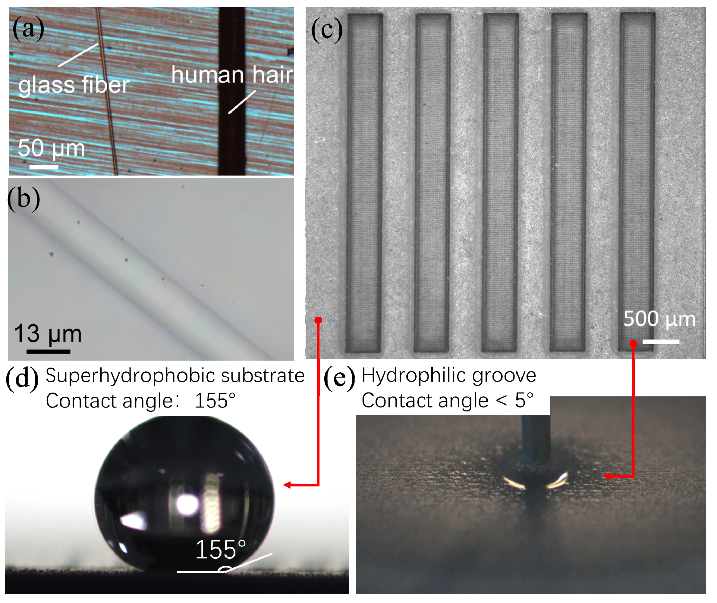
2.2. Fabrication of Hydrophilic–Superhydrophobic Grooved Surfaces
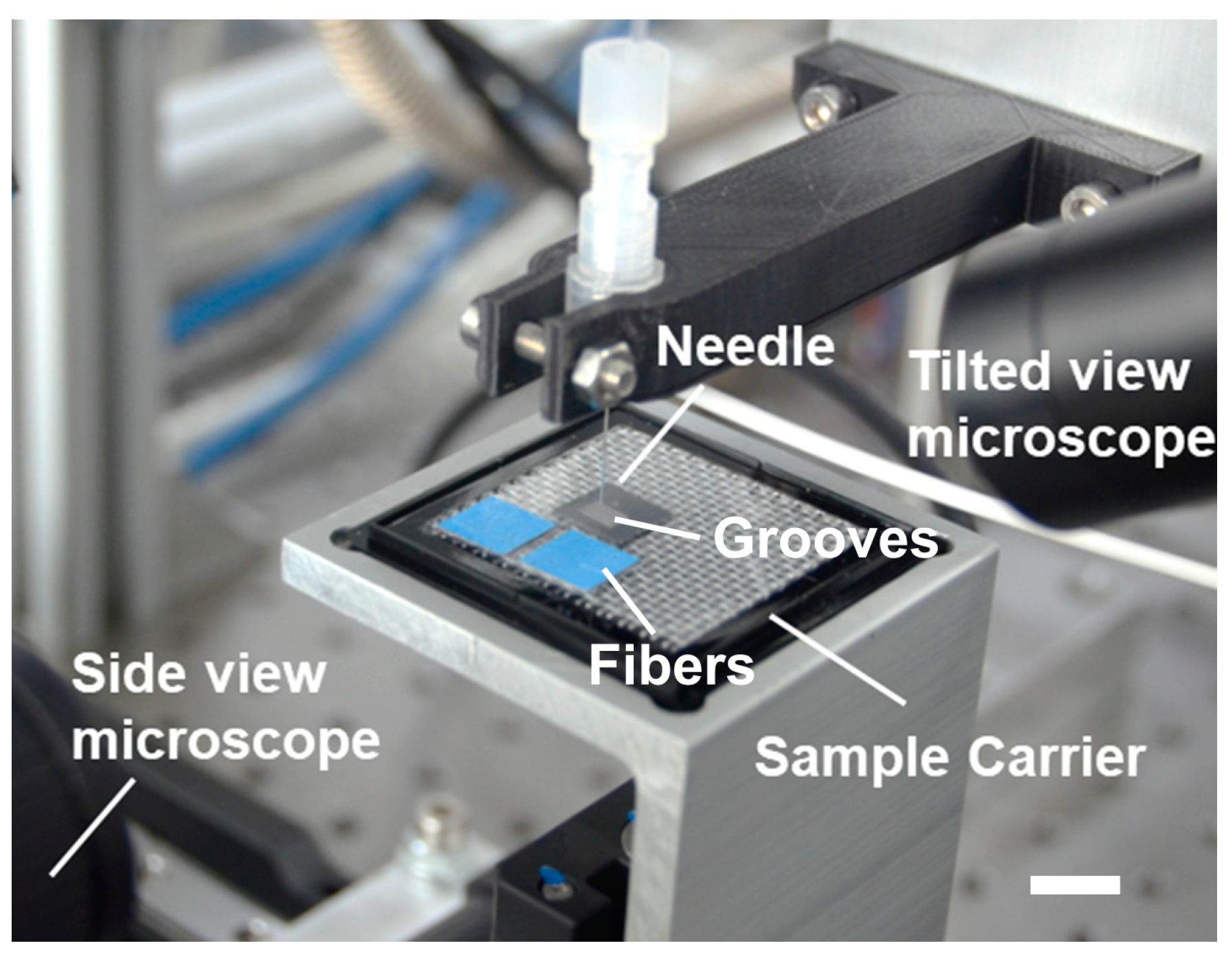
2.3. Experimental Setup
3. Results
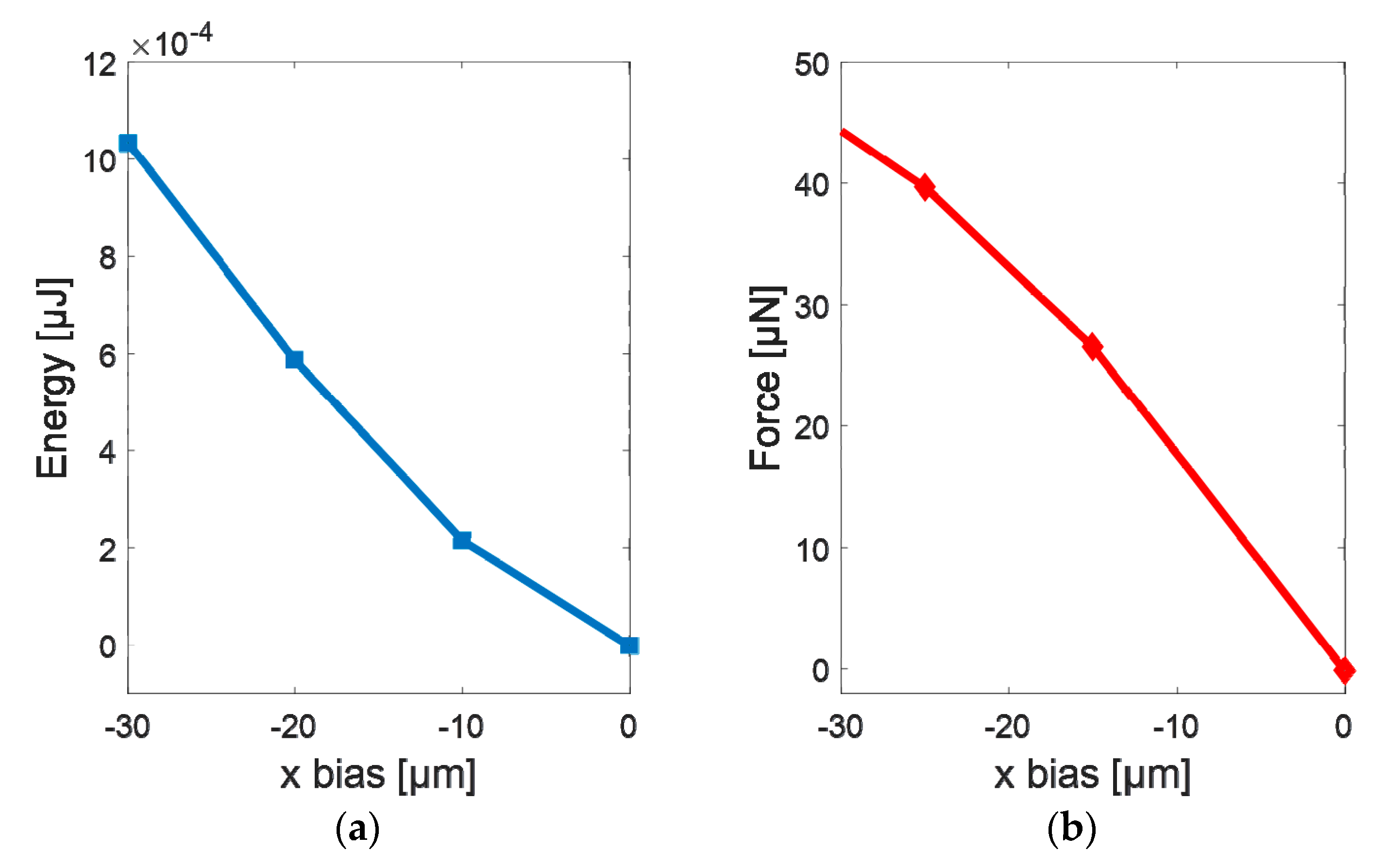
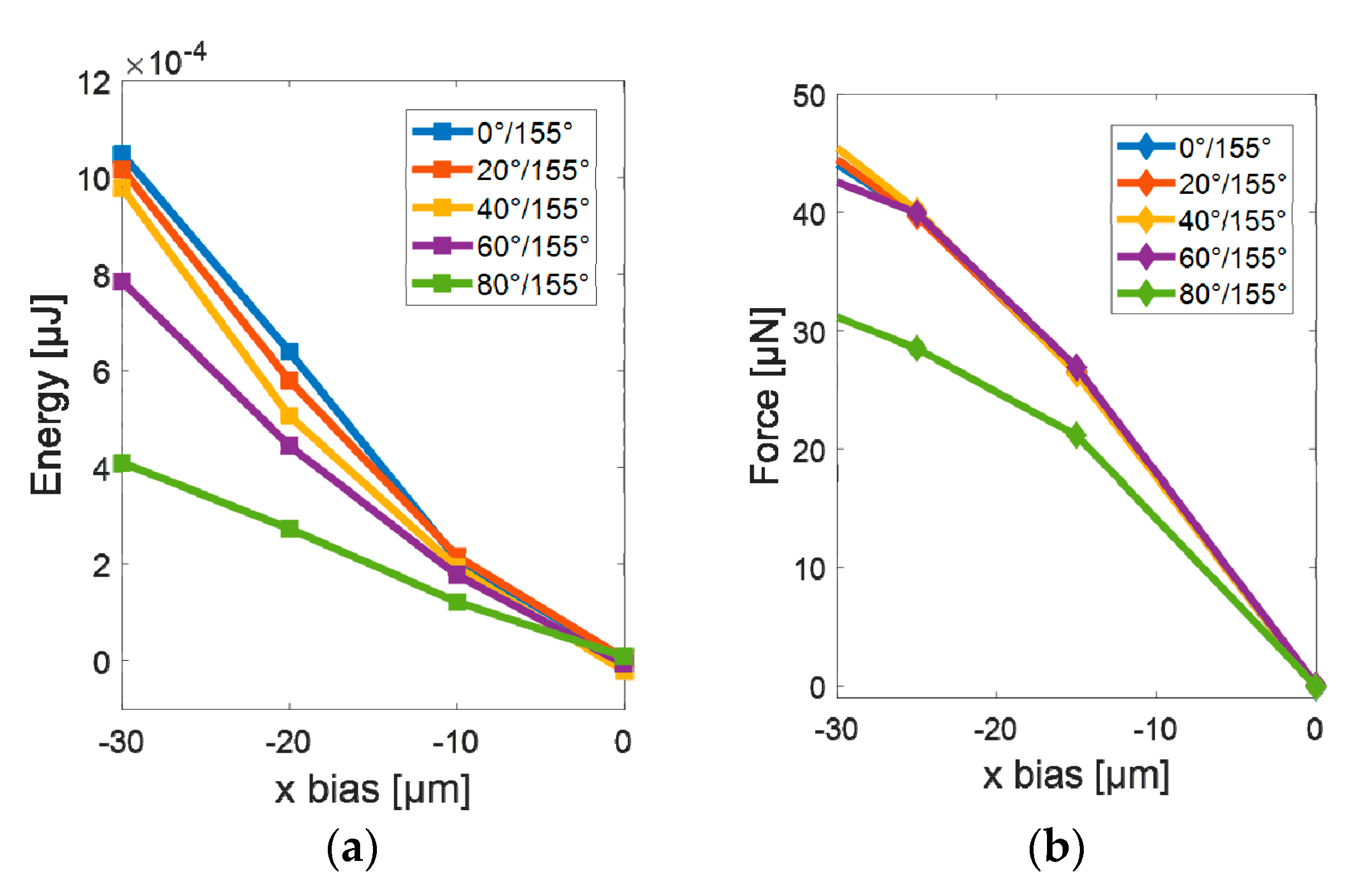
3.1. Simulations
3.2. Experimental Results
4. Discussions and Conclusions
Supplementary Materials
Author Contributions
Funding
Acknowledgments
Conflicts of Interest
References
- Greenhall, J.; Guevara Vasquez, F.; Raeymaekers, B. Ultrasound directed self-assembly of user-specified patterns of nanoparticles dispersed in a fluid medium. Appl. Phys. Lett. 2016, 108, 103103. [Google Scholar] [CrossRef]
- Gupta, P.; Rajput, M.; Singla, N.; Kumar, V.; Lahiri, D. Electric field and current assisted alignment of CNT inside polymer matrix and its effects on electrical and mechanical properties. Polymer 2016, 89, 119–127. [Google Scholar] [CrossRef]
- Fischer, J.E.; Zhou, W.; Vavro, J.; Llaguno, M.C.; Guthy, C.; Haggenmueller, R.; Casavant, M.J.; Walters, D.E.; Smalley, R.E. Magnetically aligned single wall carbon nanotube films: Preferred orientation and anisotropic transport properties. J. Appl. Phys. 2003, 93, 2157–2163. [Google Scholar] [CrossRef]
- Manoj Kumar, R.; Sharma, S.K.; Manoj Kumar, B.V.; Lahiri, D. Effects of carbon nanotube aspect ratio on strengthening and tribological behavior of ultra high molecular weight polyethylene composite. Compos. Part A Appl. Sci. Manuf. 2015, 76, 62–72. [Google Scholar] [CrossRef]
- Wang, Q.; Dai, J.; Li, W.; Wei, Z.; Jiang, J. The effects of CNT alignment on electrical conductivity and mechanical properties of SWNT/epoxy nanocomposites. Compos. Sci. Technol. 2008, 68, 1644–1648. [Google Scholar] [CrossRef]
- Ramos, J.A.; Esposito, L.; Kortaberria, G.; D’Arlas, B.F.; Zalakain, I.; Goyanes, S.; Mondragon, I. Electric field alignment of multi-walled carbon nanotubes through curing of an epoxy matrix. J. Nanostruct. Polym. Nanocompos. 2012, 8, 89–93. [Google Scholar]
- Pang, C.; Lee, G.Y.; Kim, T.I.; Kim, S.M.; Kim, H.N.; Ahn, S.H.; Suh, K.Y. A flexible and highly sensitive strain-gauge sensor using reversible interlocking of nanofibres. Nat. Mater. 2012, 11, 795–801. [Google Scholar] [CrossRef]
- Li, D.; Wang, Y.; Xia, Y. Electrospinning of polymeric and ceramic nanofibers as uniaxially aligned arrays. Nano Lett. 2003, 3, 1167–1171. [Google Scholar] [CrossRef]
- Liu, Y.; Zhang, X.; Xia, Y.; Yang, H. Magnetic-field-assisted electrospinning of aligned straight and wavy polymeric nanofibers. Adv. Mater. 2010, 22, 2454–2457. [Google Scholar] [CrossRef]
- Arras, M.M.L.; Grasl, C.; Bergmeister, H.; Schima, H. Electrospinning of aligned fibers with adjustable orientation using auxiliary electrodes. Sci. Technol. Adv. Mater. 2012, 13, 035008. [Google Scholar] [CrossRef]
- Subramanian, A.; Krishnan, U.M.; Sethuraman, S. Fabrication of uniaxially aligned 3D electrospun scaffolds for neural regeneration. Biomed. Mater. 2011, 6, 025004. [Google Scholar] [CrossRef]
- Brown, T.D.; Dalton, P.D.; Hutmacher, D.W. Direct writing by way of melt electrospinning. Adv. Mater. 2011, 23, 5651–5657. [Google Scholar] [CrossRef]
- Yu, Y.; Hua, S.; Yang, M.; Fu, Z.; Teng, S.; Niu, K.; Zhao, Q.; Yi, C. Fabrication and characterization of electrospinning/3D printing bone tissue engineering scaffold. RSC Adv. 2016, 6, 110557–110565. [Google Scholar] [CrossRef]
- Costantini, M.; Testa, S.; Mozetic, P.; Barbetta, A.; Fuoco, C.; Fornetti, E.; Tamiro, F.; Bernardini, S.; Jaroszewicz, J.; Święszkowski, W.; et al. Microfluidic-enhanced 3D bioprinting of aligned myoblast-laden hydrogels leads to functionally organized myofibers in vitro and in vivo. Biomaterials 2017, 131, 98–110. [Google Scholar] [CrossRef] [PubMed]
- Saketi, P.; Treimanis, A.; Fardim, P.; Ronkanen, P.; Kallio, P.; Hirvonen, J.; Kallio, P.; Sun, T.; Li, X.; Shi, Q.; et al. Electrospinning and electrospun nanofibers: Methods, materials, and applications. Materials 2019, 6, 2611. [Google Scholar]
- Hirvonen, J.; Von Essen, M.; Kallio, P. Automated microrobotic manipulation of paper fiber bonds. In Proceedings of the IEEE International Conference on Intelligent Robots and Systems, Hamburg, Germany, 17 December 2015. [Google Scholar]
- Von Essen, M.; Hirvonen, J.; Kuikka, S.; Kallio, P. Towards fully automated pick and place operations of individual natural fibers. In Proceedings of the 2013 International Conference on Manipulation, Manufacturing and Measurement on the Nanoscale, 3M-NANO 2013—Conference Proceedings, Suzhou, China, 26–30 August 2013. [Google Scholar]
- Sun, T.; Li, X.; Shi, Q.; Wang, H.; Huang, Q.; Fukuda, T. Microfluidic Spun Alginate Hydrogel Microfibers and Their Application in Tissue Engineering. Gels 2018, 4, 38. [Google Scholar] [CrossRef]
- Zhang, X.; Weng, L.; Liu, Q.; Li, D.; Deng, B. Facile fabrication and characterization on alginate microfibres with grooved structure via microfluidic spinning. R. Soc. Open Sci. 2019, 6, 181928. [Google Scholar] [CrossRef] [PubMed]
- Jeong, Y.H.; Lee, J. Fabrication of microfiber patterns with ivy shoot-like geometries using improved electrospinning. Materials 2016, 9, 266. [Google Scholar] [CrossRef] [PubMed]
- Chang, B.; Zhou, Q.; Wu, Z.; Liu, Z.; Ras, R.; Hjort, K. Capillary Self-Alignment of Microchips on Soft Substrates. Micromachines 2016, 7, 41. [Google Scholar] [CrossRef]
- Chang, B.; Sariola, V.; Jääskeläinen, M.; Zhou, Q. Self-alignment in the stacking of microchips with mist-induced water droplets. J. Micromech. Microeng. 2011, 21, 015016. [Google Scholar] [CrossRef]
- Sariola, V.; Jääskeläinen, M.; Zhou, Q. Hybrid microassembly combining robotics and water droplet self-alignment. IEEE Trans. Robot. 2010, 26, 965–977. [Google Scholar] [CrossRef]
- Chang, B.; Liu, H.; Ras, R.H.A.; Zhou, Q. Capillary Transport of Miniature Soft Ribbons. Micromachines 2019, 10, 684. [Google Scholar] [CrossRef]
- Chang, B.; Zhu, Z.; Koverola, M.; Zhou, Q. Laser-Assisted Mist Capillary Self-Alignment. Micromachines 2017, 8, 361. [Google Scholar] [CrossRef] [PubMed]
- Mastrangeli, M.; Zhou, Q.; Sariola, V.; Lambert, P. Surface tension-driven self-alignment. Soft Matter 2017, 13, 304–327. [Google Scholar] [CrossRef] [PubMed]
- Ito, Y.; Fukushima, T.; Lee, K.W.; Tanaka, T.; Koyanagi, M. Capillary Self-Assembly for 3D Heterogeneous System Integration and Packaging. MRS Adv. 2016, 1, 2355–2366. [Google Scholar] [CrossRef]
- Ito, Y.; Fukushima, T.; Kino, H.; Lee, K.W.; Tanaka, T.; Koyanagi, M. Impact of Chip-Edge Structures on Alignment Accuracies of Self-Assembled Dies for Microelectronic System Integration. J. Microelectromech. Syst. 2016, 25, 91–100. [Google Scholar] [CrossRef]
- Lambert, P.; Mastrangeli, M.; Valsamis, J.B.; Degrez, G. Spectral analysis and experimental study of lateral capillary dynamics for flip-chip applications. Microfluid. Nanofluid. 2010, 9, 797–807. [Google Scholar] [CrossRef]
- Arutinov, G.; Smits, E.C.P.; Albert, P.; Lambert, P.; Mastrangeli, M. In-plane mode dynamics of capillary self-alignment. Langmuir 2014, 30, 13092–13102. [Google Scholar] [CrossRef]
- Zhou, Q.; Sariola, V.; Chang, B. Towards hybrid assembly of RFIDs. In Proceedings of the Smart Systems Integration 2010—4th European Conference and Exhibition on Integration Issues of Miniaturized Systems—MEMS, MOEMS, ICs and Electronic Components, Como, Italy, 23–24 March 2010. [Google Scholar]
- Brakke, K.A. The Surface Evolver. Exp. Math. 1992, 1, 141–165. [Google Scholar] [CrossRef]


| Volume [nL] | Success Rate |
|---|---|
| 40 | 100% |
| 30 | 100% |
| 20 | 100% |
| 10 | 100% |
| 5 | 80% |
| 1 | 0% |
| Bias [µm] | Success Rate |
|---|---|
| 250 | 100% |
| 200 | 100% |
| 150 | 100% |
| 100 | 100% |
| 50 | 100% |
Publisher’s Note: MDPI stays neutral with regard to jurisdictional claims in published maps and institutional affiliations. |
© 2020 by the authors. Licensee MDPI, Basel, Switzerland. This article is an open access article distributed under the terms and conditions of the Creative Commons Attribution (CC BY) license (http://creativecommons.org/licenses/by/4.0/).
Share and Cite
Chang, B.; Jin, J.; Zhou, Q. Surface Tension-Based Alignment of Microfibers on Hydrophilic–Superhydrophobic Grooved Surfaces. Micromachines 2020, 11, 973. https://doi.org/10.3390/mi11110973
Chang B, Jin J, Zhou Q. Surface Tension-Based Alignment of Microfibers on Hydrophilic–Superhydrophobic Grooved Surfaces. Micromachines. 2020; 11(11):973. https://doi.org/10.3390/mi11110973
Chicago/Turabian StyleChang, Bo, Jialong Jin, and Quan Zhou. 2020. "Surface Tension-Based Alignment of Microfibers on Hydrophilic–Superhydrophobic Grooved Surfaces" Micromachines 11, no. 11: 973. https://doi.org/10.3390/mi11110973
APA StyleChang, B., Jin, J., & Zhou, Q. (2020). Surface Tension-Based Alignment of Microfibers on Hydrophilic–Superhydrophobic Grooved Surfaces. Micromachines, 11(11), 973. https://doi.org/10.3390/mi11110973