1. Introduction
Micro gyroscopes are widely used in inertial navigation and guidance systems. However the error and disturbances existing in micro gyroscopes may decrease the accuracy and sensitivity of the system. With the advancement of microelectromechanical system (MEMS) technology, it is possible to produce chip-based sensors such as accelerometers, gyroscopes, and magnetometers, in combination with the miniaturization of electronic devices. Micro gyroscopes are small, lightweight, have low energy consumption, long service life, and are extremely low cost.
Many control strategies have been investigated to compensate the error and disturbance from micro gyroscopes [
1,
2,
3,
4,
5,
6,
7]. Some intelligent controllers are widely used in dynamic systems because of their good capacity to approximate any unknown smooth functions [
8,
9,
10,
11,
12]. Adaptive sliding mode controllers are combined with intelligent controllers for dynamic systems [
13,
14,
15,
16,
17]. Thee backstepping method is widely used in dynamic systems with pure feedback or strict feedback forms. The backstepping adaptive fuzzy control method has received great interest in recent years [
18]. Neural control and fuzzy control have the capacity to approximate unknown smooth functions and have been widely used in identification and control [
19,
20,
21,
22,
23,
24,
25,
26,
27,
28,
29,
30].
The universal approximation theorem indicates that the fuzzy system is a new universal approximator in addition to polynomial function approximators and neural network approximators. As the universal approximation theory of fuzzy system can approximate any nonlinear model and realize arbitrary nonlinear control law, it is widely used in control systems. Adaptive sliding mode control with a neural estimator and adaptive control with fuzzy compensator for a micro gyroscope was investigated in [
31,
32]. In [
33], a fuzzy system was used to approximate the system nonlinearities and a finite time convergent sliding mode controller was designed. Backstepping design is a powerful tool for dynamic systems with pure or strict feedback forms. In recent years, the backstepping control techniques have received great attention due to their systematic and recursive design methodology for nonlinear feedback control. The key idea of the backstepping technique is to recursively select some appropriate functions of state variables as fictitious control inputs for lower dimension subsystems of the overall system. Lin et al. [
34] and Lee et al. [
35] introduced an adaptive fuzzy backstepping control method for uncertain nonlinear systems. Lin et al. [
36] proposed an adaptive fuzzy sliding-mode control for linear ultrasonic servomotor systems.
However, the fuzzy control strategy is not combined with an adaptive backstepping controller in the application of micro gyroscope and a backstepping controller has not been incorporated into a fuzzy sliding mode control system for a micro gyroscope. As such, the adaptive backstepping fuzzy sliding mode control approach has not been proposed in the control of a micro gyroscope. Motivated by the above research, this paper presents an adaptive backstepping fuzzy sliding controller to adjust the fuzzy parameters with self-learning ability and reject the system nonlinearities. Comparing other existing methods, the main contributions of this article can be summarized as follows:
(1) Backstepping is a nonlinear control approach by means of the recursion process. A major advantage of a backstepping controller is its flexibility to avoid cancellations of useful nonlinearities and achieve regulation and tracking properties. The gyroscope equations are transformed into an analogically cascade system where the backstepping approach can be implanted.
(2) Backstepping design and adaptive fuzzy sliding mode control were applied to a micro gyroscope. The proposed adaptive fuzzy controller not only does not rely on the system model, but also makes the algorithm adjust the fuzzy parameters with self-learning ability.
(3) The proposed sliding mode control adds additional compensators to improve the stability, hence obtaining desired system characteristics. Thus, the entire closed-loop system meets the dynamic and static performance indicators and achieves accurate tracking performance.
2. Dynamics of Micro Gyroscope
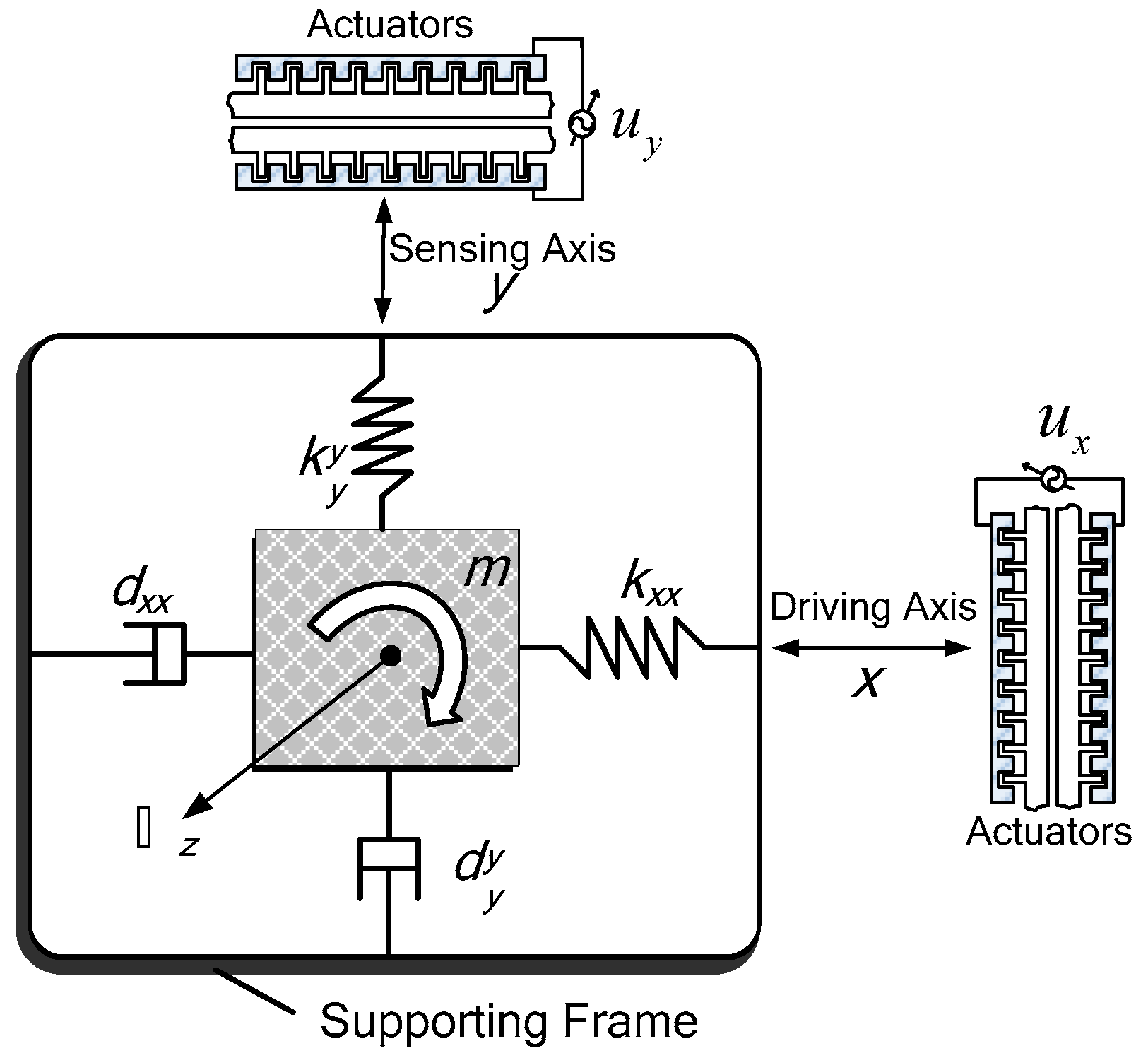
In this section, the dynamic model of a micro gyroscope is presented. The characteristics of micro gyroscopes are similar to traditional gyroscopes, mainly through the Coriolis force to achieve the miniaturization of equipment. The dynamics model of the micro gyroscope can be regarded as a damping-spring-mass system, as shown in
Figure 1.
The driving electrode generates electrostatic force to drive the base mass block back and forth to maintain stable oscillatory momentum. The induction device is used to sense the movement of the base mass block in the vertical driving direction, and to extract the external angular velocity from the vibration information. Referring to Park [
1], with some assumptions, the dynamic model of gyroscope can be expressed as
The asymmetric spring and damping terms, and , are generated from fabrication imperfections. , , , and are the and axes spring and damping terms. and are the control forces.
Dividing both sides of Equation (1) by the mass
, reference length
, and the square of the resonance frequency
yields
Define
, Equation (1) can be rewritten as
where the dimensionless quantities are
Taking into account the system nonlinearities, Equation (2) can be expressed as:
where
are the model uncertainties; and
is external disturbances of micro gyroscope.
includes lumped system nonlinearities,
. We assume
is bounded by a positive constant
.
3. Adaptive Backstepping Control Design
Motivated by the research results in [
17,
18,
19,
20,
21,
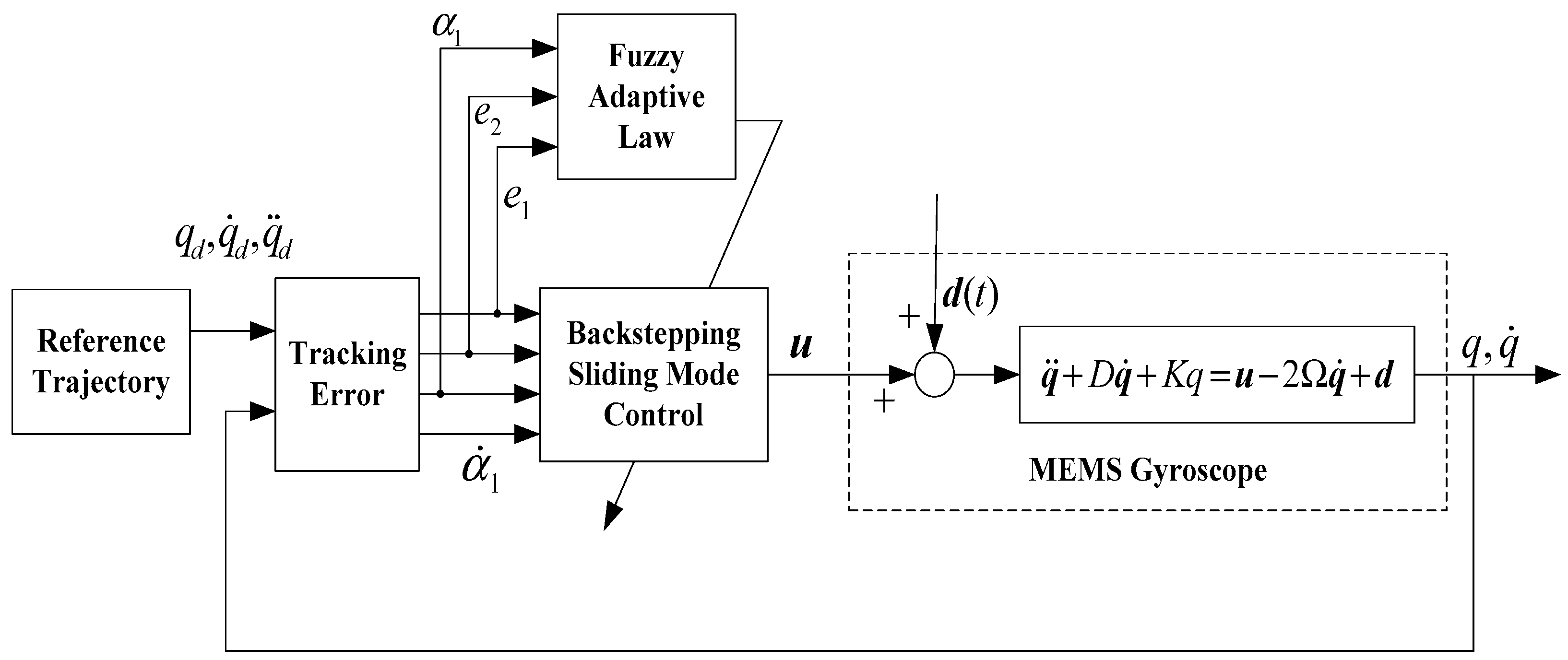
28], in this section, a backstepping controller was designed to meet the objective of tracking and stabilization by a recursive design procedure. The schematic block diagram of the proposed approach of a micro gyroscope is described in
Figure 2. The target of ABFSMC is to achieve real-time compensation for fabrication imperfections.
The reference model is defined as
. The tracking error is defined as
where
is the trajectory of the reference model virtual control volume and
is the virtual control volume, defined as
In Equation (5), is a positive constant.
We selected the first Lyapunov function as:
The time derivative of the
is
when
, it is easy to see that
.
Define a function of sliding surface as
where
is a positive constant.
Define the second Lyapunov function as
From Equation (9), we can get
Then, substituting Equation (10) into the time derivative of
becomes
where
.
In the controller design, we used exponential reaching law as
where
.
By Equations (11) and (12), we designed a comprehensive controller as
Substituting Equation (13) into Equation (11) yields
However, since the system model is unknown in practical situations, the controller (13) cannot be implemented. Then, a fuzzy system is used to approximate the unknown model of the micro gyroscope.
The singleton fuzzifier mapping was used, where
and
have the same member functions as Gaussian membership functions
where
and
are the center and width of the
th fuzzy set
, respectively.
The output of the fuzzy system is written by a center-average defuzzifier, product inference, and singleton fuzzifier as:
where
is the membership function value of the fuzzy variable
;
is the point at which the membership function of
achieves its maximum value;
is the adaptive parameter, and
are the fuzzy basis functions.
We defined the optimal approximation constant
. We made an assumption that for a given small arbitrarily positive constant
, the following inequality expression (17) holds.
Since the system model
is unknown, a fuzzy controller can be proposed as
where a fuzzy system
is used to approximate the
in (13).
4. Adaptive Estimator
In this section, the stability analysis of the proposed control system is discussed. First, we chose a Lyapunov function candidate as
where
,
.
Then, the time derivative of
becomes
From the derivation in (11),
Substituting (18) into (21) yields
Since
is bounded by a positive constant
, and making using of
and (17), (22) becomes
To make
, we chose a parameter updating law
Substituting Equation (24) into Equation (23) yields
According to the Inequality
, we can get
. Substituting this condition into Equation (25) yields
According to the inequality
, that is
, we can get
Substituting Equation (27) into Equation (26) yields
where
.
Define
, Equation (28) becomes
where
.
Solving Equation (29) yields
where
is the initial value of
. If we define a closely collection as
, we can get
.
is a negative semi-definite that ensures that
,
,
,
are all bounded. Then, the stability of the designed closed-loop control system can be guaranteed.
Remark 1. In order to overcome this problem, a proper adaptation law can be proposed to estimator the upper boundto realize the adaptive upper bound control, weakening the chattering and ensuring the stability of the control system.
Remark 2. Since there is a switching functions sign in the proposed controller (13), we can use saturation function or hyperbolic function to replace sign function to decrease chattering.
5. Simulation Study
In this section, the proposed ABFSMC scheme was evaluated on the lumped model of a micro gyroscope sensor. The simulation experiment of the proposed scheme was carried out on a MATLAB/SIMULINK software platform. Meanwhile, the superiority of the proposed can be further confirmed by comparing it with the adaptive backstepping controller [
7].
The parameters of the micro gyroscope were selected as in
Table 1.
The angular velocity of micro gyroscope was assumed to be . The dimensionless procedure was implemented. The reference length and frequency were chosen as and . The unknown angular velocity was assumed to be , and the dimensionless parameters can be calculated. The reference trajectory , , was close to their natural frequencies. Random variable signal with zero mean and unity variance was regarded as external disturbance . As for model uncertainties, we assumed there existed ±30% parameter variations for the spring and damping coefficients, and ±30% magnitude changes held in the coupling terms with respect to their nominal values.
Initial conditions were
, other parameters were selected as
,
,
,
,
,
. The membership functions were selected as
where
is the amplitude of the reference trajectory as
.
Figure 3,
Figure 4,
Figure 5,
Figure 6,
Figure 7 and
Figure 8 show the simulation results using the proposed ABFSMC approach.
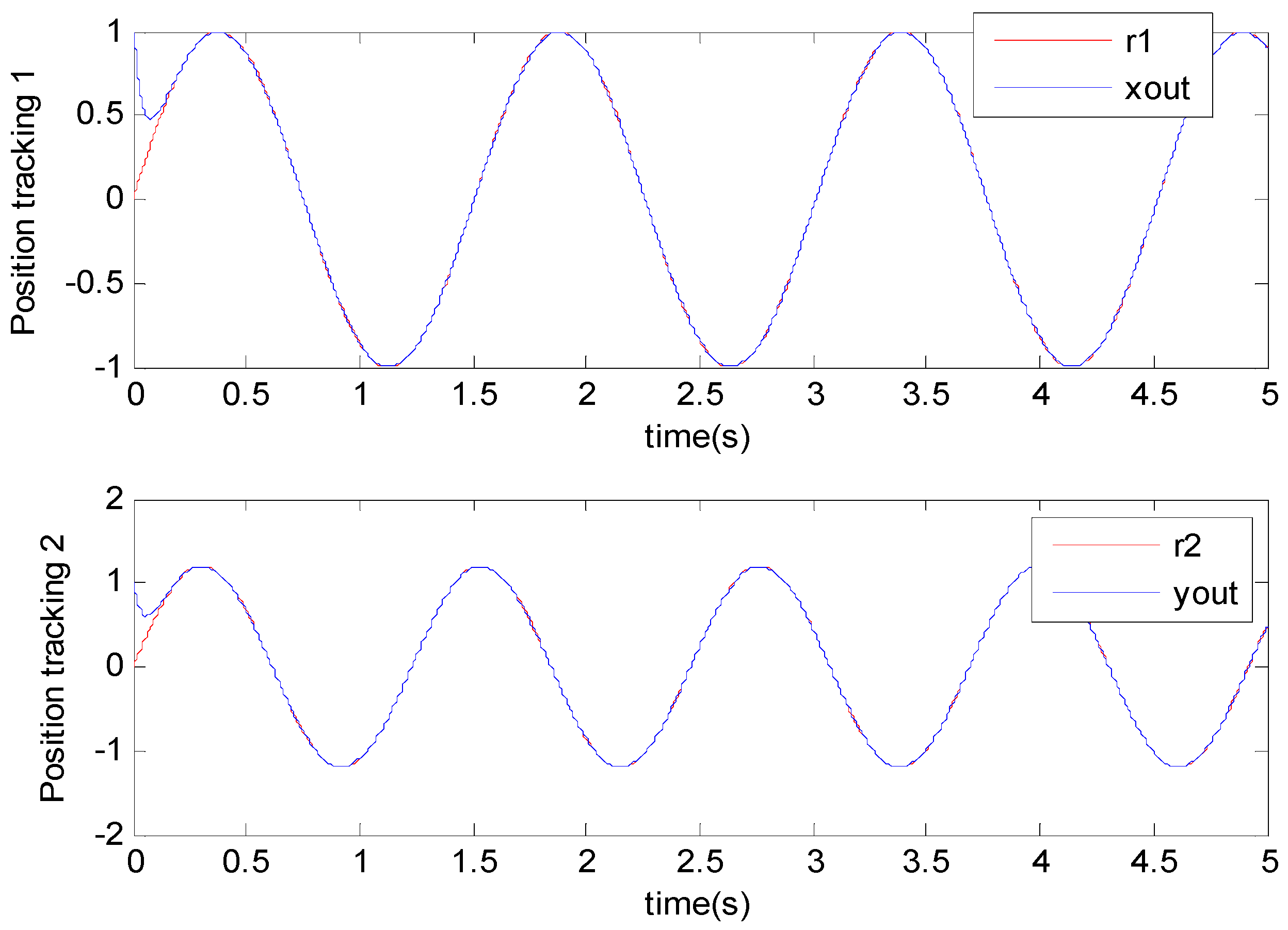
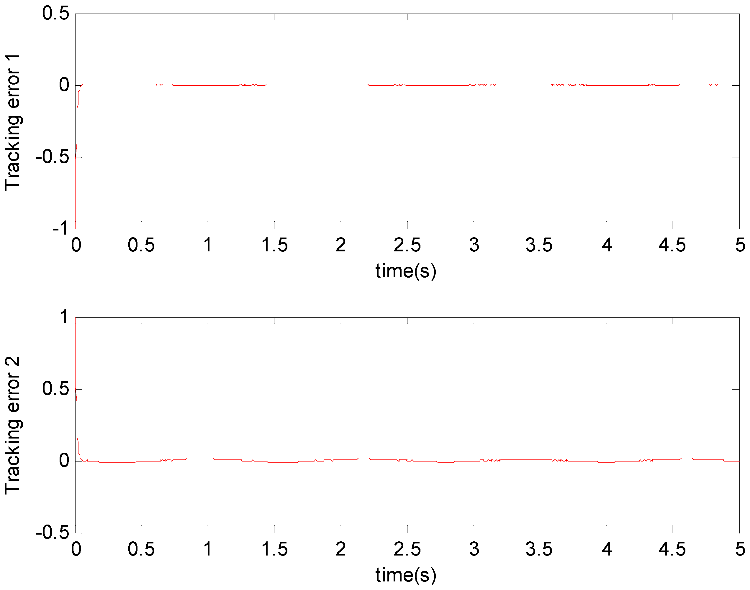
Figure 3 shows the output of micro gyroscope in the
axis to track the trajectory.
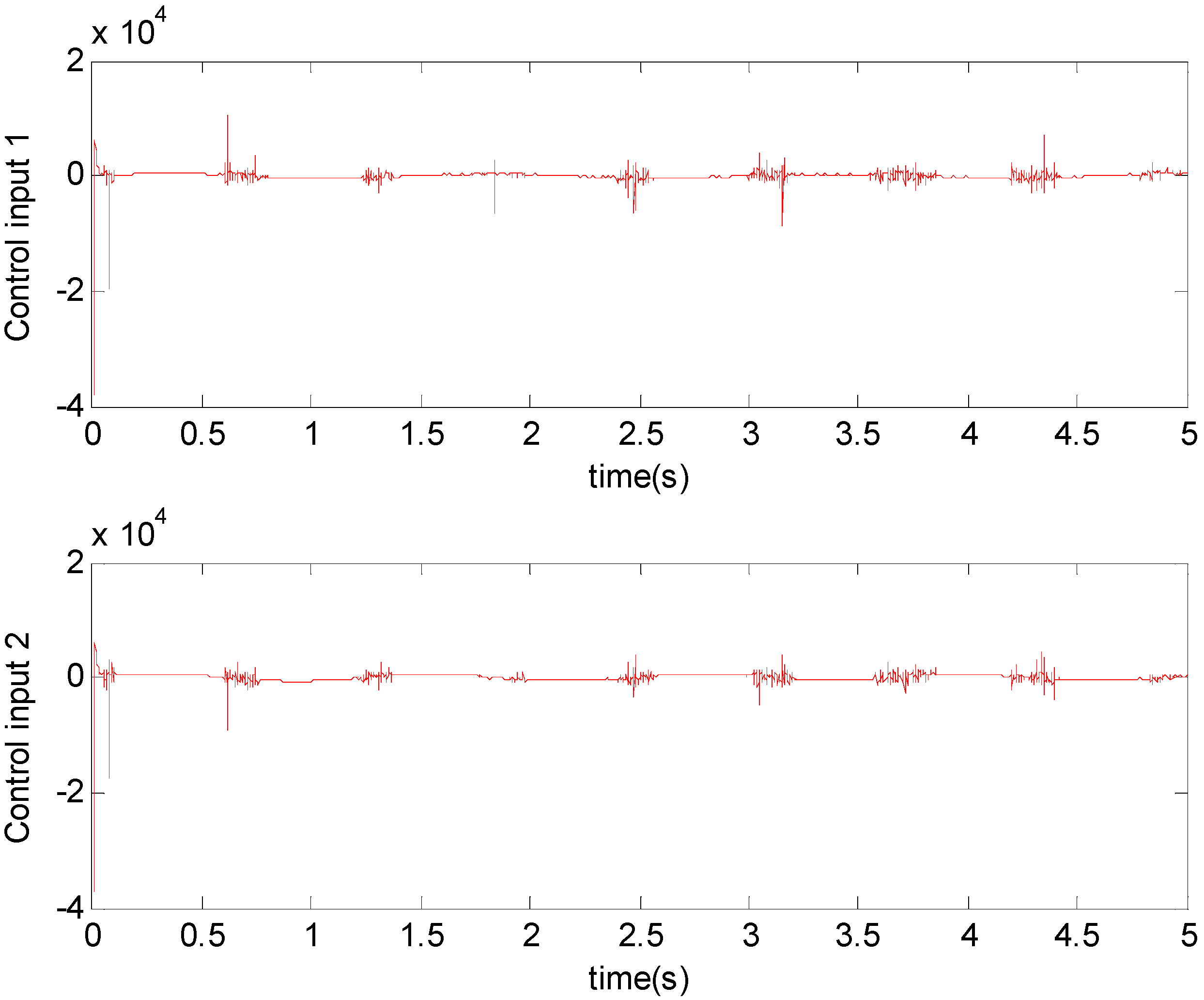
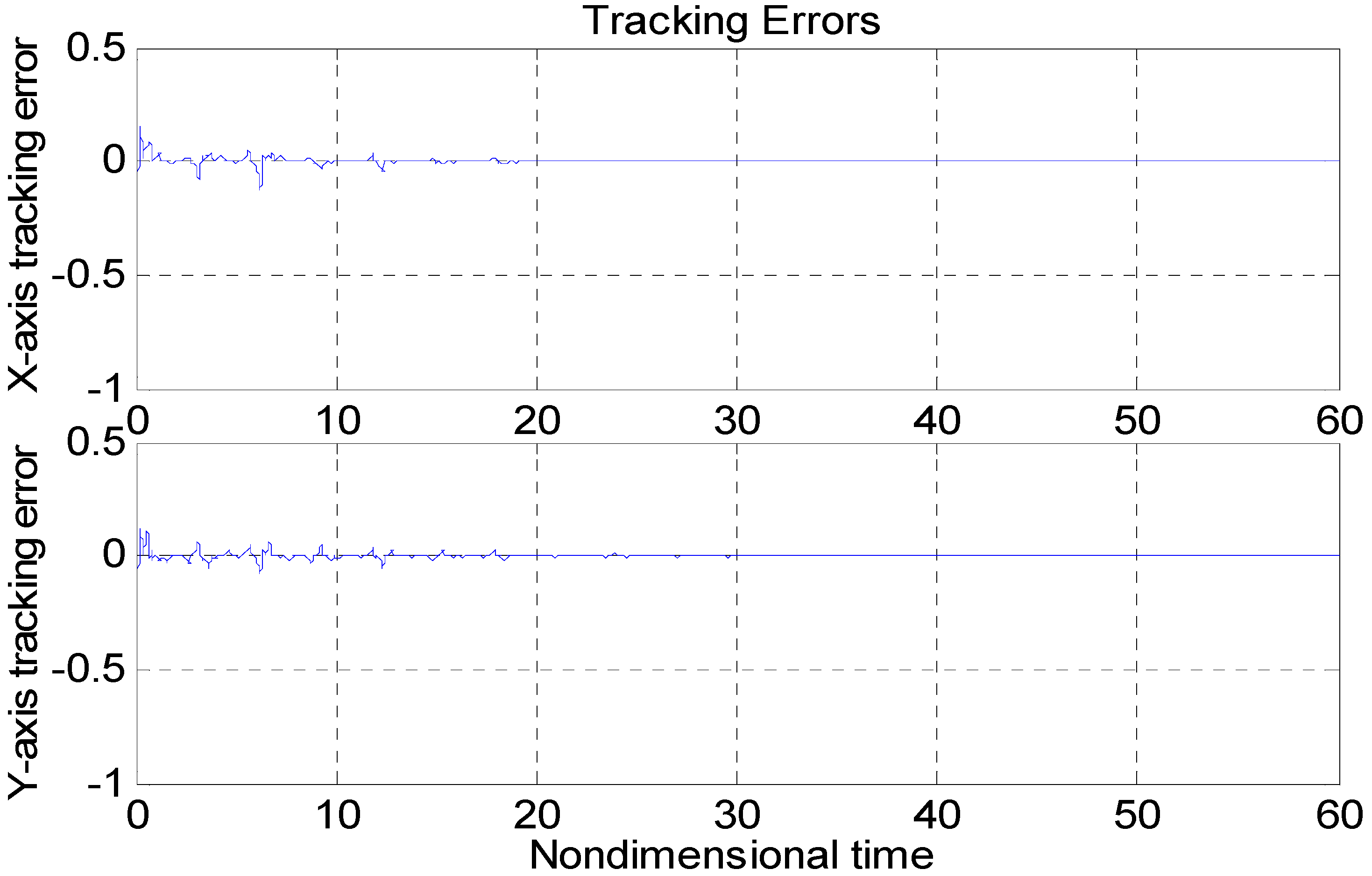
Figure 4 shows the tracking error. It was demonstrated that the trajectory of the control system could track the reference trajectory in 0.2 s. The control input using the ABFSMC approach is drawn in
Figure 5. It shows that the control input was stable between −1000 and 1000.
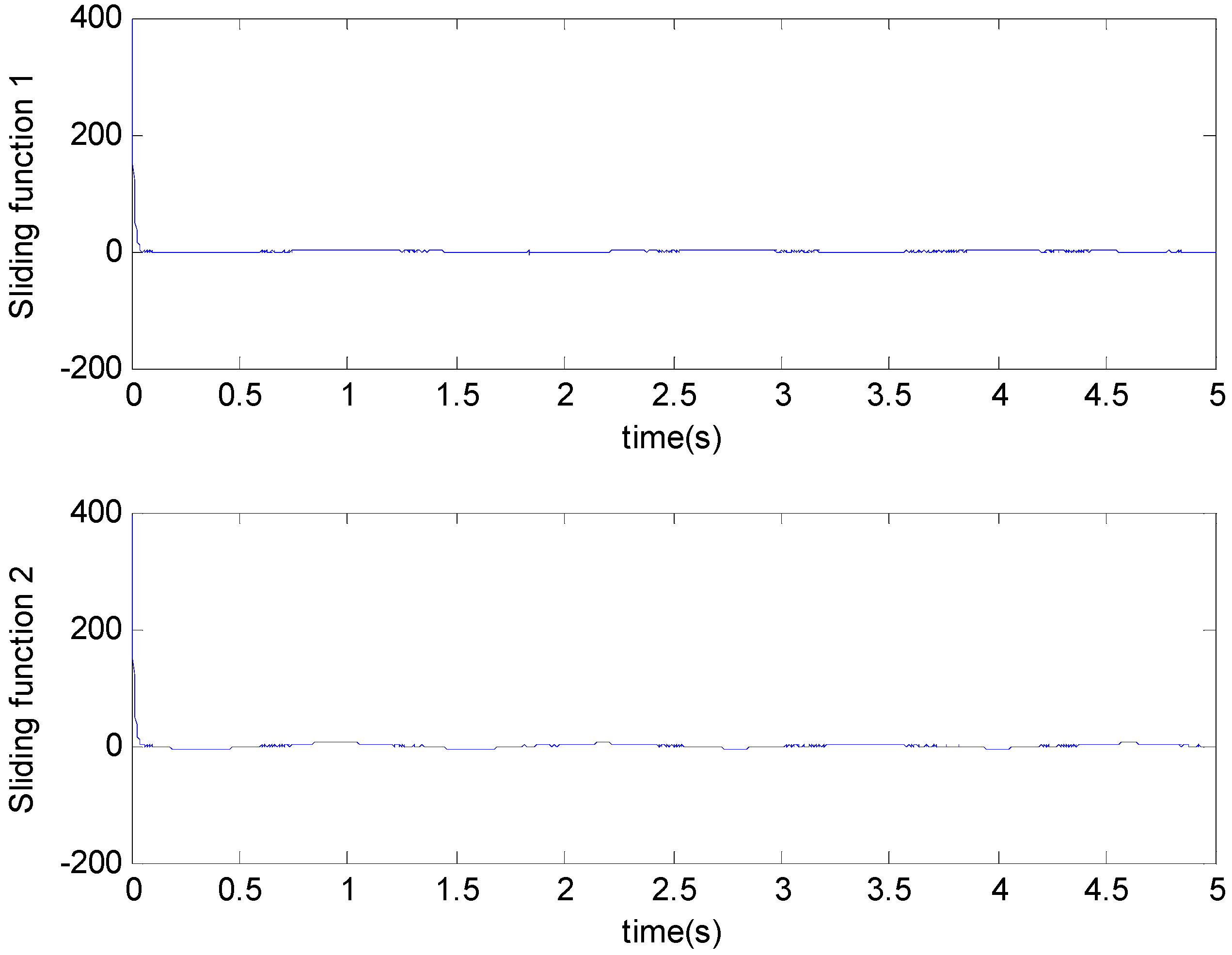
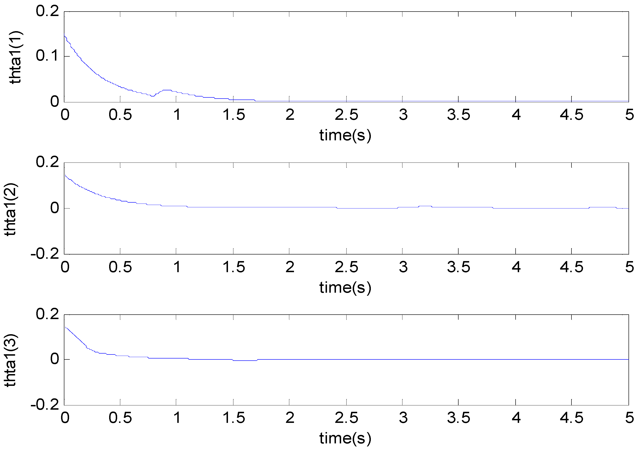
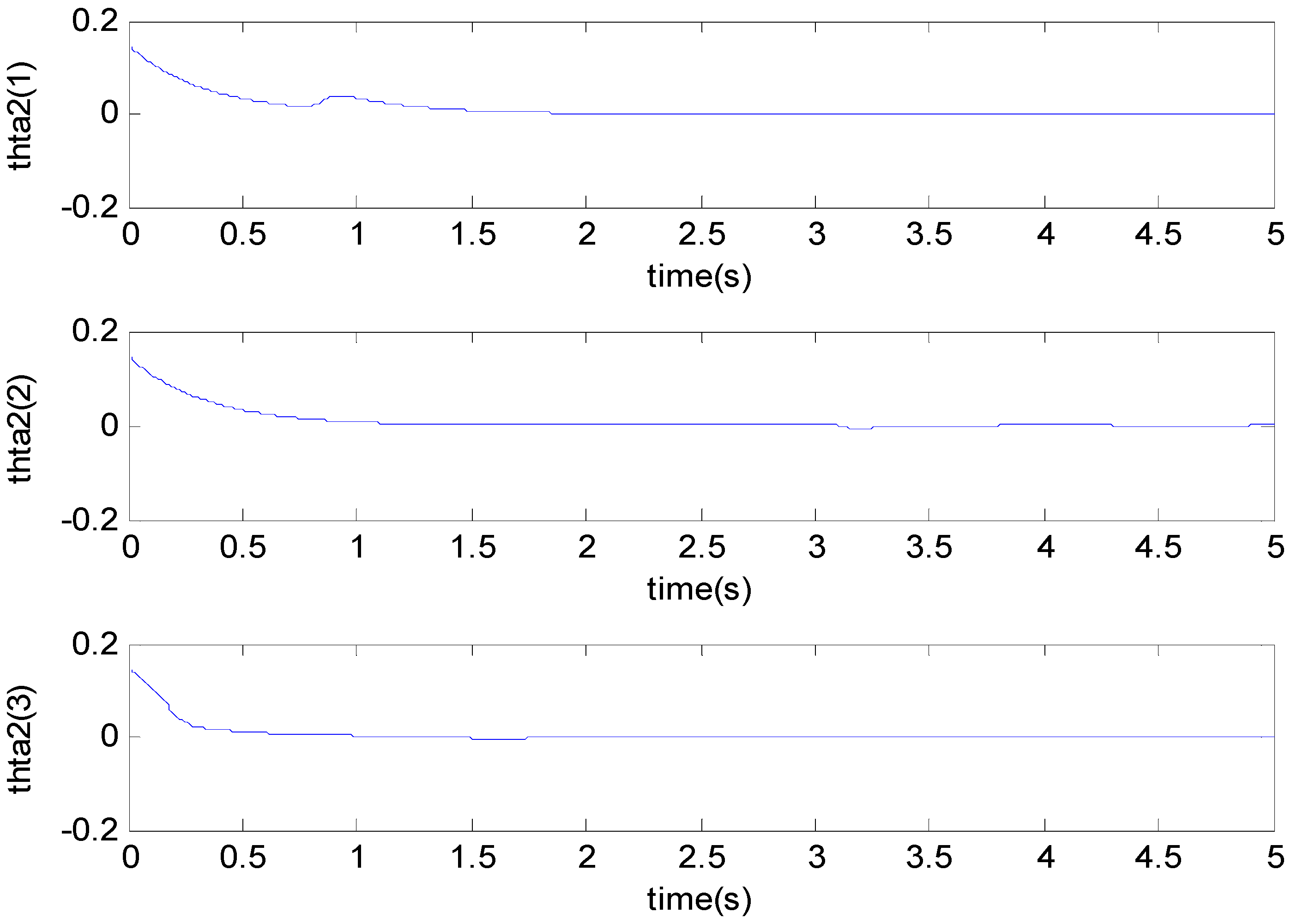
Figure 6 shows the function of the sliding mode surface. The parameters of the fuzzy adaptive control are plotted in
Figure 7 and
Figure 8, showing that the fuzzy control method combined with the adaptive control method has the ability to learn and adjust the fuzzy parameters. It is observed that the fuzzy parameters can be adjusted to the optimal value quickly and keep stable, which shows that the self-regulation fuzzy system has better stability and self-tuning performance.
An adaptive backstepping control (ABC) technique for a microscope was presented in [
7]. In order to more clearly demonstrate the advantages of the proposed method, the performance of our proposed ABFSMC strategy was compared with the ABC method in [
7] and the case without a controller.
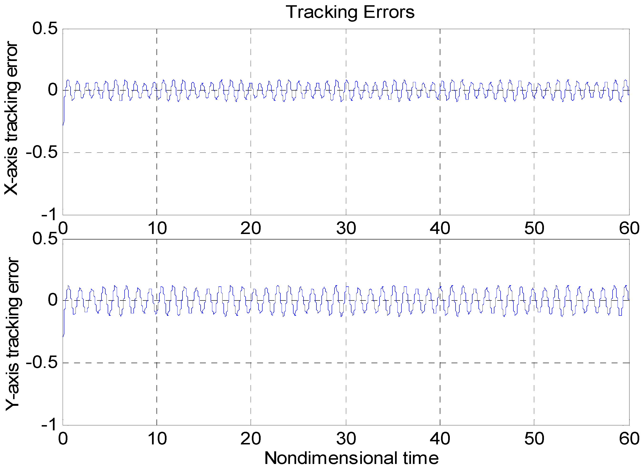
Figure 9 and
Figure 10 show the tracking property using the adaptive controller in [
7] and without using the controller, with the same nominal gyroscope parameters under the same model uncertainties. From
Figure 10, due to the modeling error, the “dull” controller relied on the nominal parameters, which led to a stable system, but the tracking errors were obvious. The tracking errors with the adaptive backstepping controller displayed quite a large overshoot at the beginning, as did the control efforts. The settling time of the tracking errors was also worse than our proposed ABFSMC controller. The advantages of our proposed controller over the adaptive backstepping controller and the case without controller were obvious.
For the quantity discussion, the root mean square errors (RMSE) of the tracking error of the two axes of the micro gyroscope using these three difference controllers are compared in
Table 2.
In summary, the introduction of the ABFSMC approach can adapt to the changes in the external disturbance and model parameters and maintain a satisfactory performance in tracking and approximation.
6. Conclusions
The ABFSMC strategy was investigated in a micro gyroscope through theoretical discussion and numerical simulation. The mathematical model of the micro gyroscope was transformed for the handiness of the backstepping control design. A backstepping approach was adopted to deal with the model uncertainties, disturbances, and unknown parameters of the micro gyroscope. The fuzzy parameters were updated online to approximate the nonlinear dynamics in the micro gyroscope. Simulation studies were investigated to demonstrate the advantages of the proposed ABFSMC strategy in tracking and approximation performance.
Author Contributions
Conceptualization, J.F.; Methodology, Y.F. and J.F.; Software, Z.Y.; Validation, Z.Y.; Formal Analysis, Y.F.; Investigation, Z.Y.; Resources, Z.Y.; Data Curation, Z.Y.; Writing—Original Draft Preparation, J.F.; Writing—Review & Editing, J.F.; Visualization, Y.F.; Supervision, J.F.; Project Administration, J.F.; Funding Acquisition, J.F. All authors have read and agreed to the published version of the manuscript.
Funding
This work was partially supported by the National Science Foundation of China under grant No. 61873085.
Acknowledgments
The authors thank the anonymous reviewers for their useful comments that improved the quality of the paper.
Conflicts of Interest
The authors declare no conflict of interest.
References
- Fei, J.; Yang, Y. Comparative Study of System Identification Approaches for Adaptive Tracking of Mems Gyroscope. Int. J. Robot. Autom. 2012, 27, 322–329. [Google Scholar] [CrossRef]
- Park, S.; Horowitz, R.; Hong, S.-K.; Nam, Y. Trajectory-Switching Algorithm for a MEMS Gyroscope. IEEE Trans. Instrum. Meas. 2007, 56, 2561–2569. [Google Scholar] [CrossRef]
- Leland, R. Adaptive control of a MEMS gyroscope using Lyapunov methods. IEEE Trans. Control. Syst. Technol. 2006, 14, 278–283. [Google Scholar] [CrossRef]
- Fei, J.; Batur, C. A novel adaptive sliding mode control with application to MEMS gyroscope. ISA Trans. 2009, 48, 73–78. [Google Scholar] [CrossRef] [PubMed]
- Wang, W.; Lv, X.; Sun, F. Design of micro machined vibratory gyroscope with two degree-of-freedom drive-mode and sense-mode. IEEE Sens. J. 2012, 12, 2460–2464. [Google Scholar] [CrossRef]
- Chen, F.; Yuan, W.; Chang, H.; Yuan, G.; Xie, J.; Kraft, M. Design and Implementation of an Optimized Double Closed-Loop Control System for MEMS Vibratory Gyroscope. IEEE Sens. J. 2013, 14, 184–196. [Google Scholar] [CrossRef]
- Fang, Y.; Fei, J.; Yang, Y. Adaptive Backstepping Design of a Microgyroscope. Micromachines 2018, 9, 338. [Google Scholar] [CrossRef] [PubMed]
- Ma, L.; Wang, C.; Ding, S.; Dong, L. Integral sliding mode control for stochastic Markovian jump system with time-varying delay. Neurocomputing 2016, 179, 118–125. [Google Scholar] [CrossRef]
- Wang, H.; Liu, P.X.; Zhao, X.; Liu, X. Adaptive Fuzzy Finite-Time Control of Nonlinear Systems with Actuator Faults. IEEE Trans. Cybern. 2019, 50, 1786–1797. [Google Scholar] [CrossRef]
- Wang, H.; Liu, P.X.; Xie, X.-J.; Liu, X.; Hayat, T.; Alsaadi, F.E. Adaptive fuzzy asymptotical tracking control of nonlinear systems with unmodeled dynamics and quantized actuator. Inf. Sci. 2018. [Google Scholar] [CrossRef]
- Wang, H.; Liu, P.X.; Bao, J.; Xie, X.-J.; Li, S. Adaptive Neural Output-Feedback Decentralized Control for Large-Scale Nonlinear Systems with Stochastic Disturbances. IEEE Trans. Neural Netw. Learn. Syst. 2019, 31, 972–983. [Google Scholar] [CrossRef]
- Zhao, X.; Wang, X.; Zong, G.; Li, H. Fuzzy-Approximation-Based Adaptive Output-Feedback Control for Uncertain Nonsmooth Nonlinear Systems. IEEE Trans. Fuzzy Syst. 2018, 26, 3847–3859. [Google Scholar] [CrossRef]
- Zhu, L.; Wang, Z.; Zhou, Y.; Liu, Y. Adaptive Neural Network Saturated Control for MDF Continuous Hot Pressing Hydraulic System with Uncertainties. IEEE Access 2018, 6, 2266–2273. [Google Scholar] [CrossRef]
- Fei, J.; Lu, C. Adaptive Sliding Mode Control of Dynamic Systems Using Double Loop Recurrent Neural Network Structure. IEEE Trans. Neural Netw. Learn. Syst. 2018, 29, 1275–1286. [Google Scholar] [CrossRef]
- Ho, T.H.; Ahn, K.K. Speed Control of a Hydraulic Pressure Coupling Drive Using an Adaptive Fuzzy Sliding-Mode Control. IEEE/ASME Trans. Mechatron. 2011, 17, 976–986. [Google Scholar] [CrossRef]
- Wang, X.; Li, X.; Wang, J.; Fang, X.; Zhu, X. Data-driven model-free adaptive sliding mode control for the multi degree-of-freedom robotic exoskeleton. Inf. Sci. 2016, 327, 246–257. [Google Scholar] [CrossRef]
- Precup, R.-E.; Radac, M.-B.; Roman, R.-C.; Petriu, E.M. Model-free sliding mode control of nonlinear systems: Algorithms and experiments. Inf. Sci. 2017, 381, 176–192. [Google Scholar] [CrossRef]
- Fei, J.; Wang, T. Adaptive fuzzy-neural-network based on RBFNN control for active power filter. Int. J. Mach. Learn. Cybern. 2018, 10, 1139–1150. [Google Scholar] [CrossRef]
- Zhao, D.; Zou, T.; Li, S.; Zhu, Q. Adaptive backstepping sliding mode control for leader–follower multi-agent systems. IET Control Theory Appl. 2012, 6, 1109–1117. [Google Scholar] [CrossRef]
- Zhu, Y.; Fei, J. Disturbance Observer Based Fuzzy Sliding Mode Control of PV Grid Connected Inverter. IEEE Access 2018, 6, 21202–21211. [Google Scholar] [CrossRef]
- Fei, J.; Wang, H. Experimental Investigation of Recurrent Neural Network Fractional-order Sliding Mode Control for Active Power Filter. IEEE Trans. Circuits Syst. II-Express Briefs 2019. [Google Scholar] [CrossRef]
- Fang, Y.; Fei, J.; Cao, D. Adaptive Fuzzy-Neural Fractional-Order Current Control of Active Power Filter with Finite-Time Sliding Controller. Int. J. Fuzzy Syst. 2019, 21, 1533–1543. [Google Scholar] [CrossRef]
- Fei, J.; Feng, Z. Adaptive Fuzzy Super-Twisting Sliding Mode Control for Microgyroscope. Complexity 2019, 2019, 1–13. [Google Scholar] [CrossRef]
- Chu, Y.; Fei, J.; Hou, S. Adaptive Global Sliding-Mode Control for Dynamic Systems Using Double Hidden Layer Recurrent Neural Network Structure. IEEE Trans. Neural Netw. Learn. Syst. 2019, 31, 1297–1309. [Google Scholar] [CrossRef] [PubMed]
- Fang, Y.; Fei, J.; Hu, T. Adaptive Backstepping Fuzzy Sliding Mode Vibration Control of Flexible Structure. J. Low Freq. Noise Vib. Act. Control 2018, 37, 1079–2096. [Google Scholar] [CrossRef]
- Fei, J.; Chu, Y. Double Hidden Layer Recurrent Neural Adaptive Global Sliding Mode Control of Active Power Filter. IEEE Trans. Power Electron. 2019. [Google Scholar] [CrossRef]
- Fei, J.; Ding, H. Adaptive sliding mode control of dynamic system using RBF neural network. Nonlinear Dyn. 2012, 70, 1563–1573. [Google Scholar] [CrossRef]
- Fei, J.; Chen, Y. Fuzzy Double Hidden Layer Recurrent Neural Terminal Sliding Mode Control of Single-Phase Active Power Filter. IEEE Trans. Fuzzy Syst. 2020. [Google Scholar] [CrossRef]
- Fei, J.; Chen, Y. Dynamic Terminal Sliding Mode Control for Single-Phase Active Power Filter Using Double Hidden Layer Recurrent Neural Network. IEEE Trans. Power Electron. 2020, 35, 9906–9924. [Google Scholar] [CrossRef]
- Fei, J.; Feng, Z. Fractional-Order Finite-Time Super-Twisting Sliding Mode Control of Micro Gyroscope Based on Double-Loop Fuzzy Neural Network. IEEE Trans. Syst. Man Cybern. Syst. 2020, 1–15. [Google Scholar] [CrossRef]
- Fei, J.; Lu, C. Adaptive fractional order sliding mode controller with neural estimator. J. Frankl. Inst. 2018, 355, 2369–2391. [Google Scholar] [CrossRef]
- Fei, J.; Zhou, J. Robust Adaptive Control of MEMS Triaxial Gyroscope Using Fuzzy Compensator. IEEE Trans. Syst. Man Cybern. Part B (Cybern.) 2012, 42, 1599–1607. [Google Scholar] [CrossRef]
- Ren, J.; Zhang, R.; Xu, B. Adaptive Fuzzy Sliding Mode Control of MEMS Gyroscope with Finite Time Convergence. J. Sens. 2016, 2016, 267–273. [Google Scholar] [CrossRef]
- Lin, C.-M.; Li, H.-Y. TSK Fuzzy CMAC-Based Robust Adaptive Backstepping Control for Uncertain Nonlinear Systems. IEEE Trans. Fuzzy Syst. 2012, 20, 1147–1154. [Google Scholar] [CrossRef]
- Lee, H. Robust Adaptive Fuzzy Control by Backstepping for a Class of MIMO Nonlinear Systems. IEEE Trans. Fuzzy Syst. 2010, 19, 265–275. [Google Scholar] [CrossRef]
- Lin, F.-J.; Shieh, P.-H.; Chou, P.-H. Robust Adaptive Backstepping Motion Control of Linear Ultrasonic Motors Using Fuzzy Neural Network. IEEE Trans. Fuzzy Syst. 2008, 16, 676–692. [Google Scholar] [CrossRef]
| Publisher’s Note: MDPI stays neutral with regard to jurisdictional claims in published maps and institutional affiliations. |
© 2020 by the authors. Licensee MDPI, Basel, Switzerland. This article is an open access article distributed under the terms and conditions of the Creative Commons Attribution (CC BY) license (http://creativecommons.org/licenses/by/4.0/).


