Eight Element Side Edged Framed MIMO Antenna Array for Future 5G Smart Phones

 ,
,  ,
,  , , , and
Abstract
1. Introduction
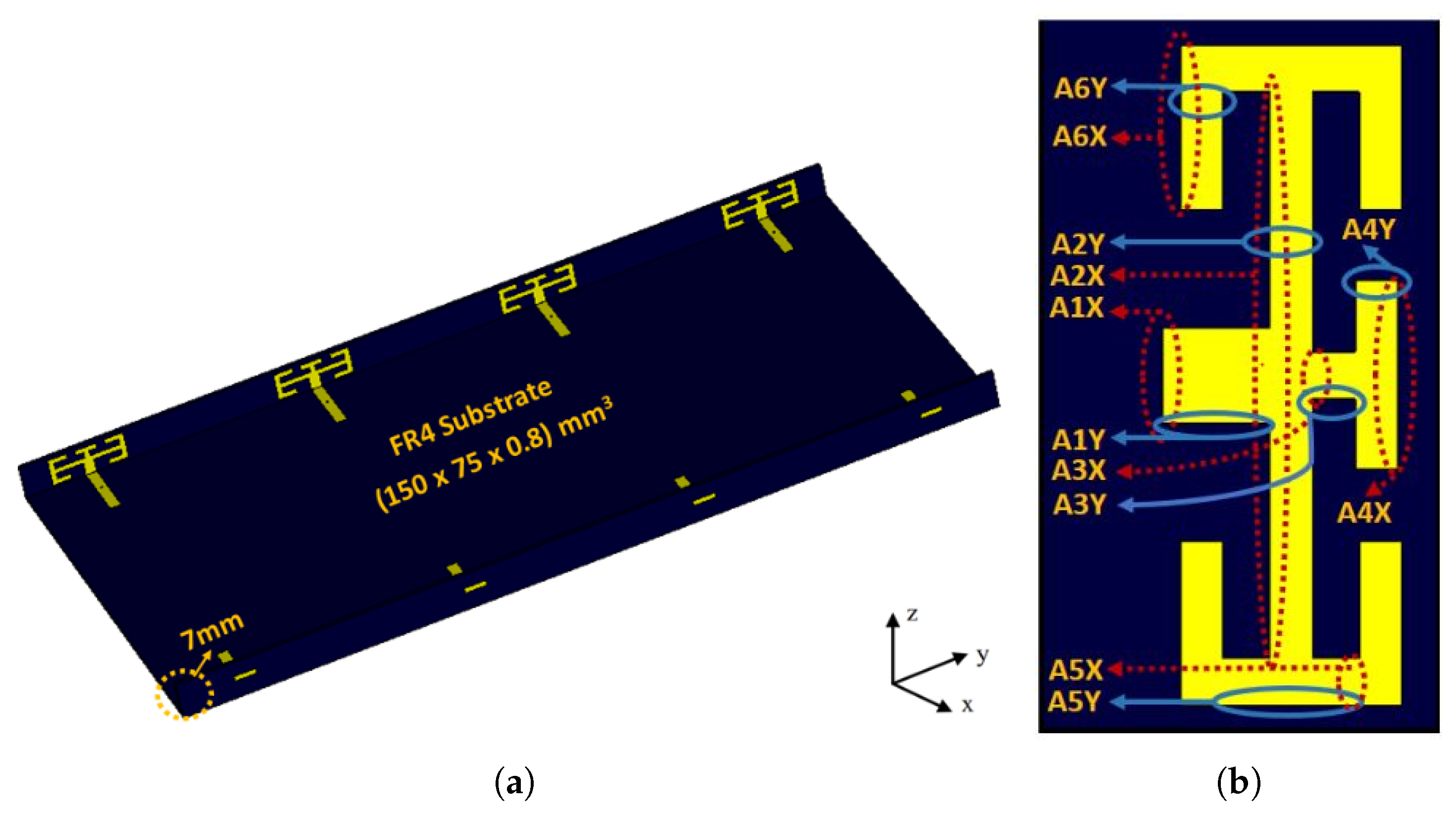
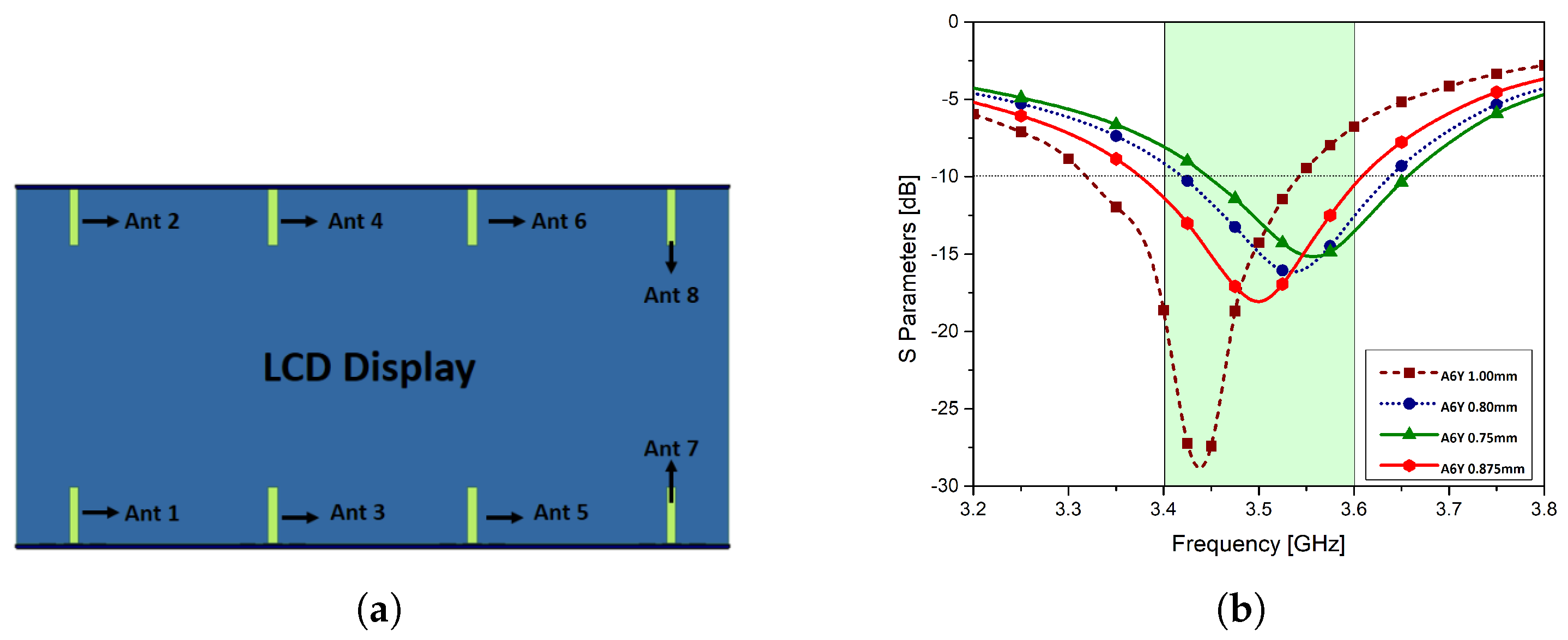
2. Antenna Design
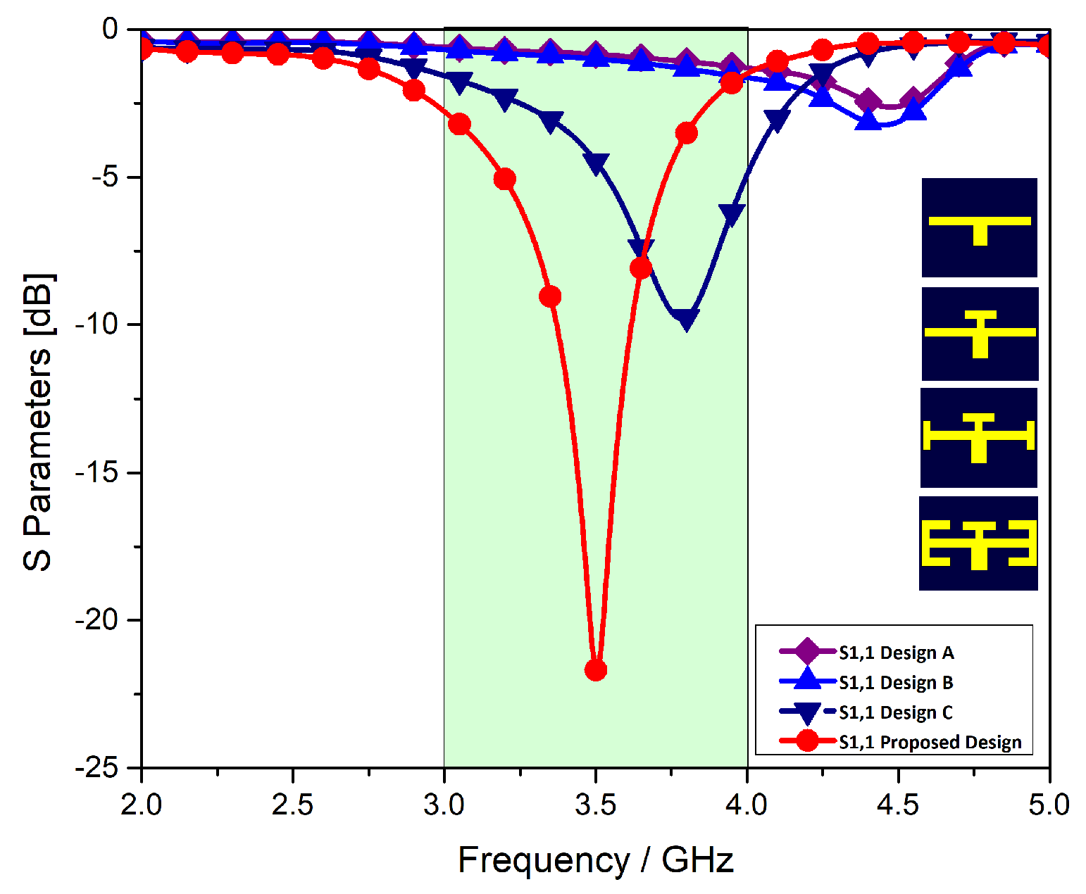
Design Evolution
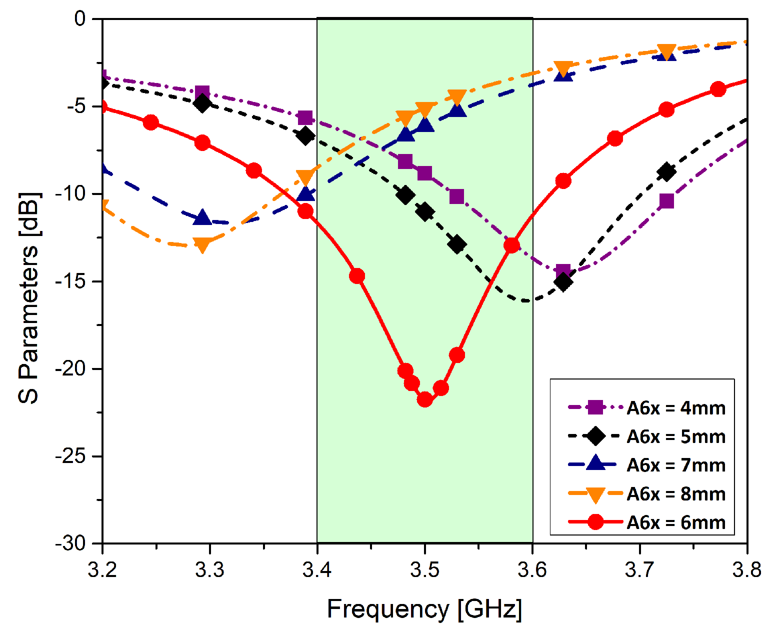
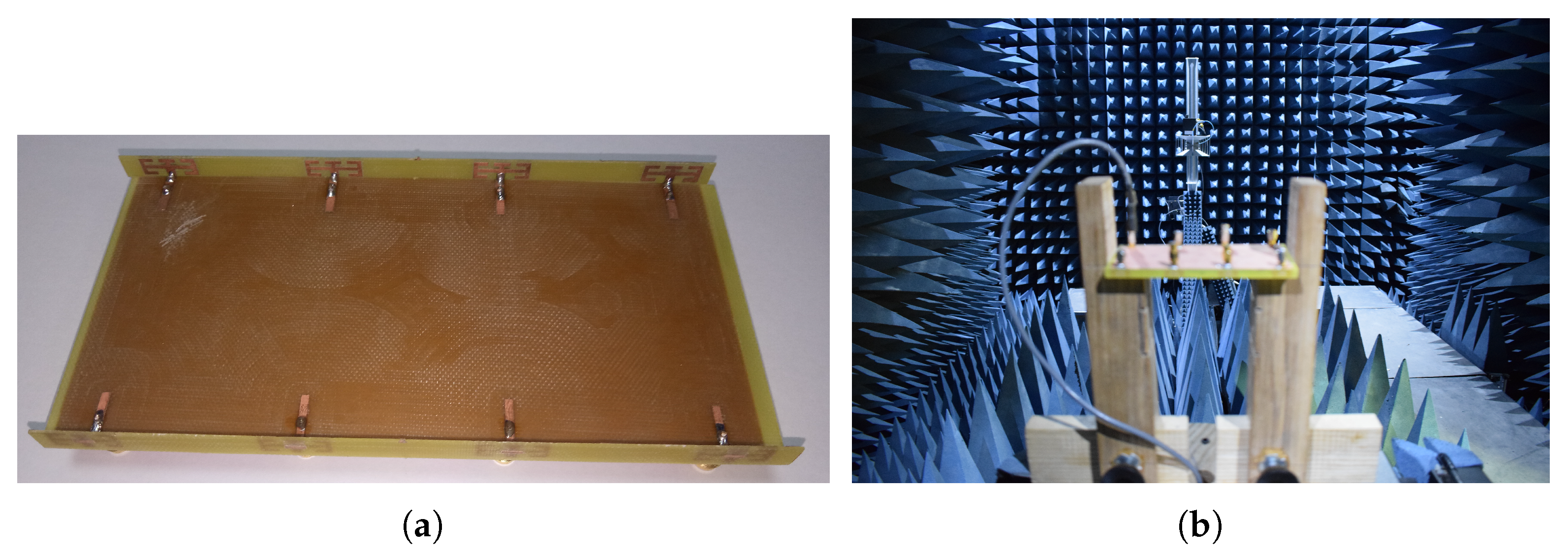
3. Results and Discussion
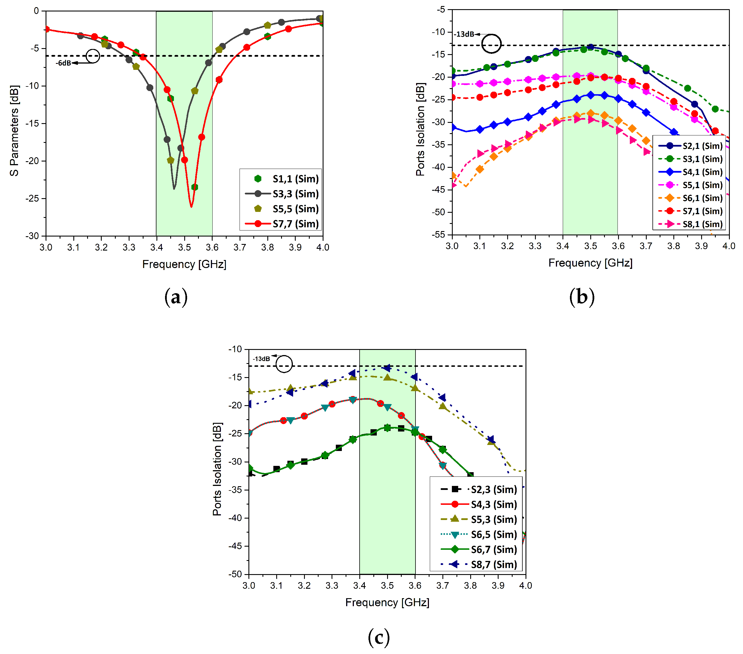
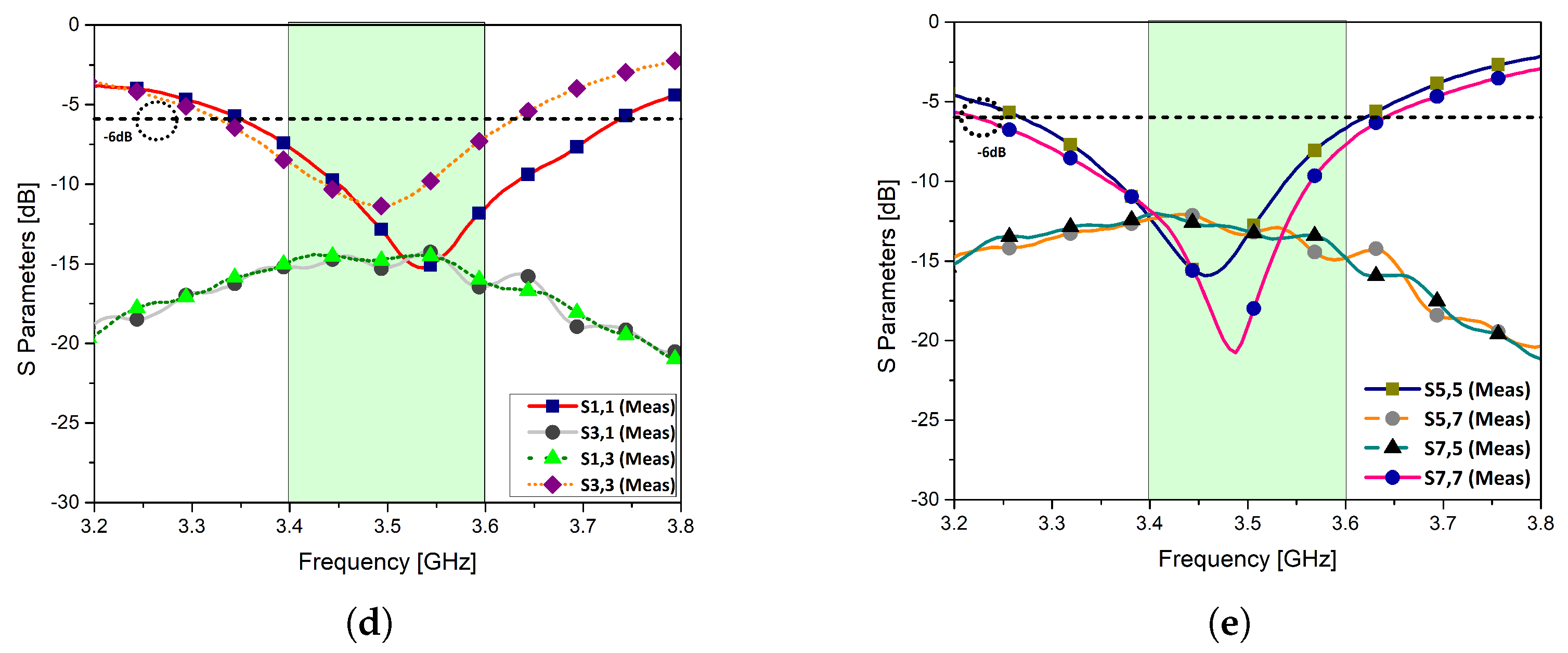
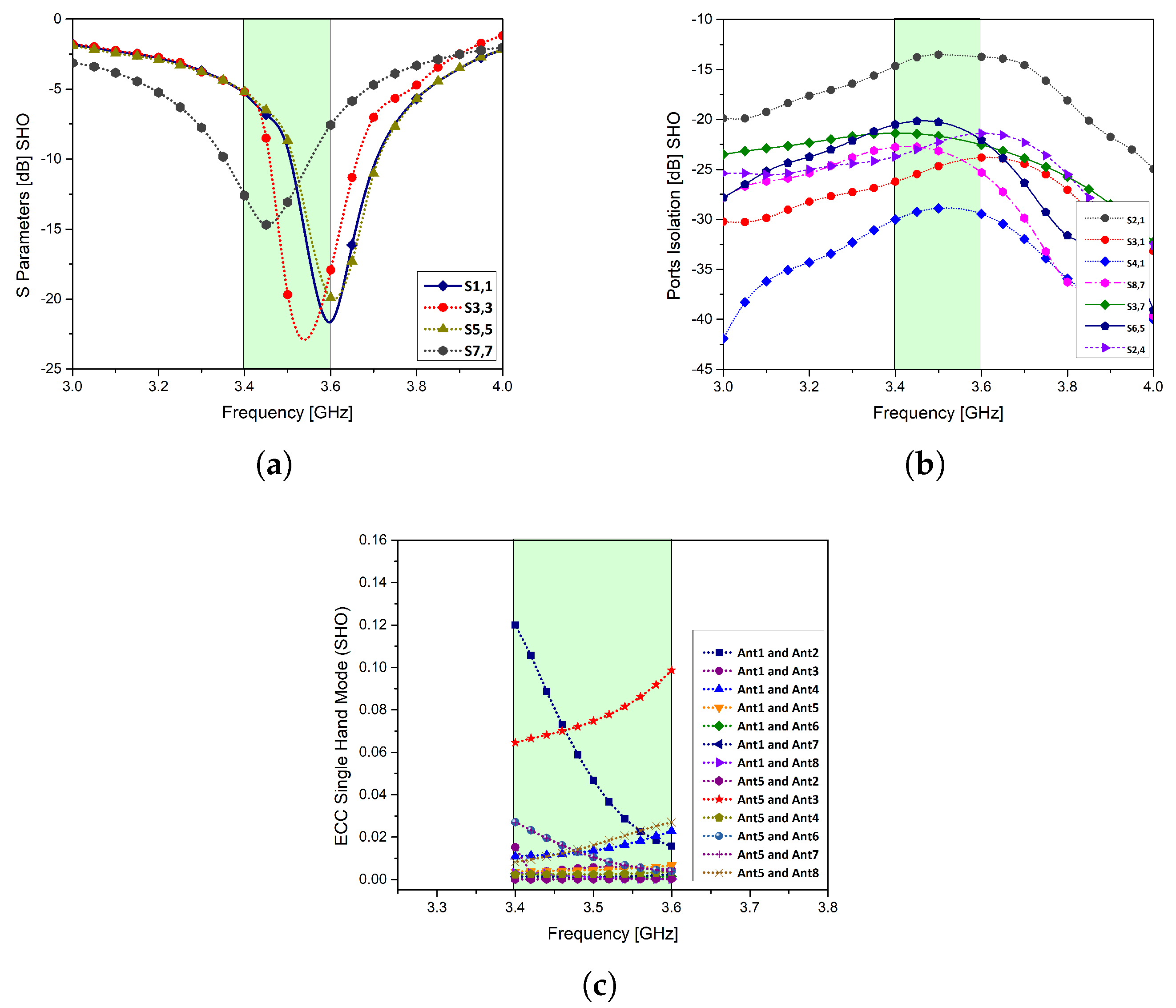
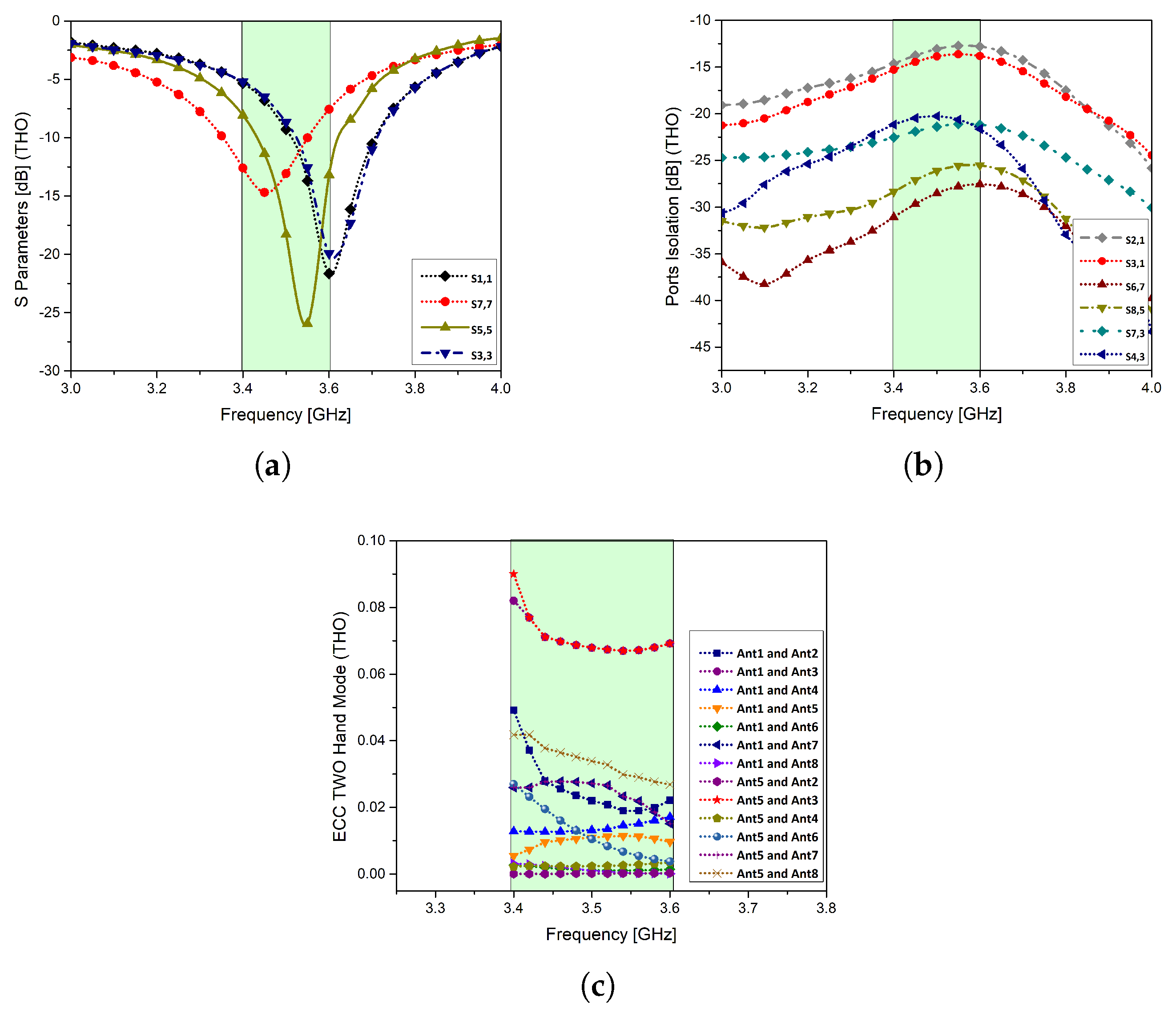
3.1. S Parameter Analysis
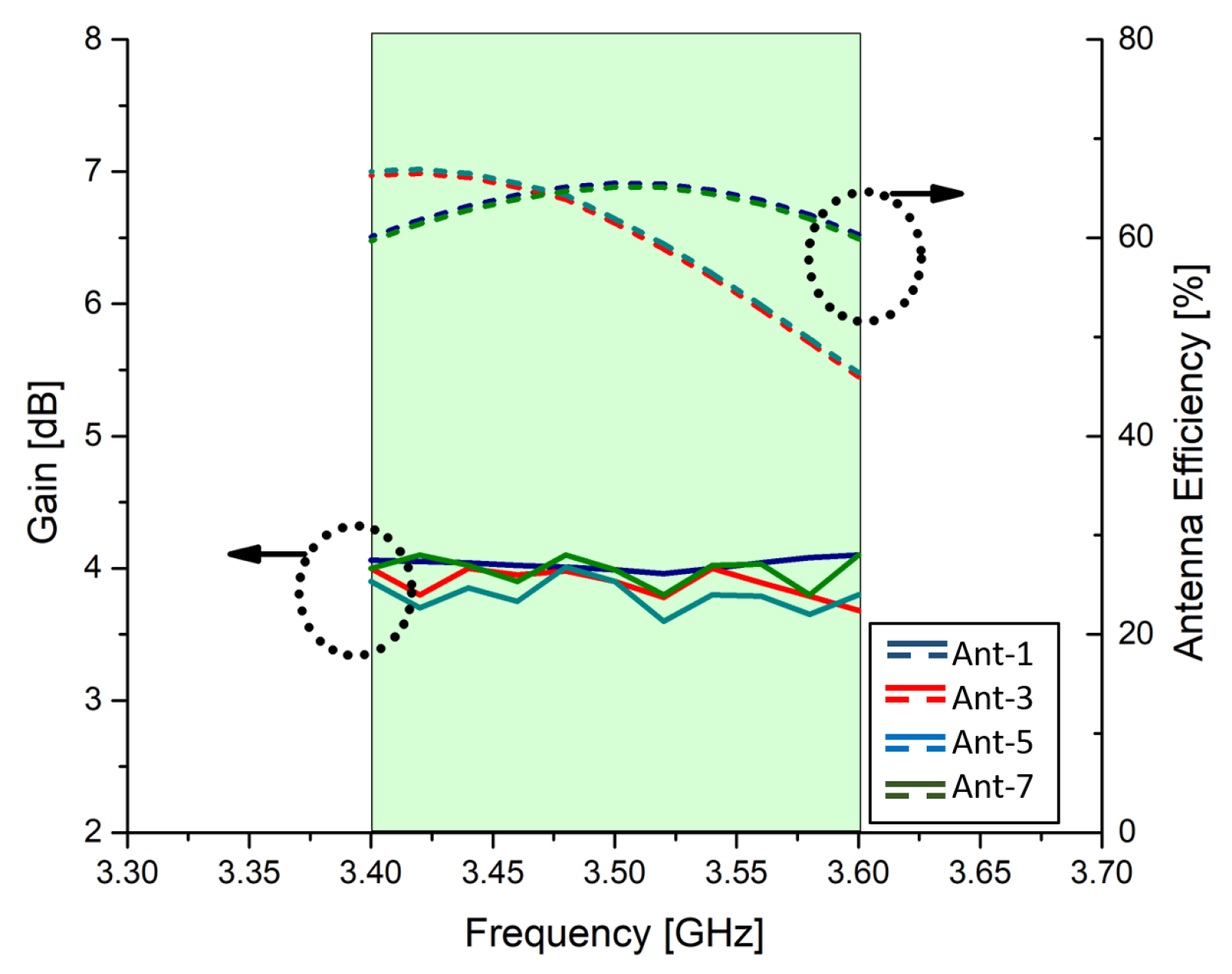
3.2. Efficiencies
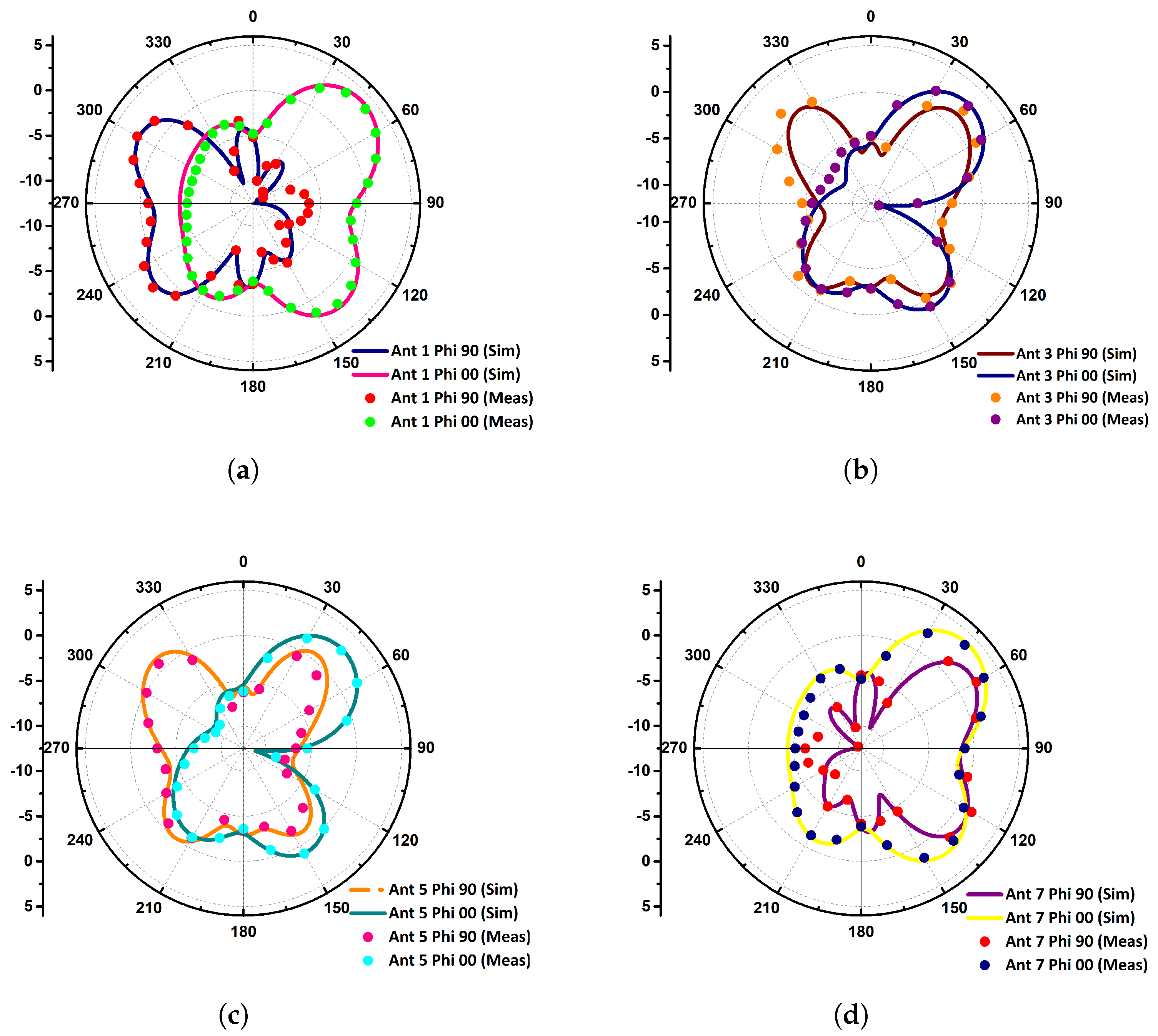
3.3. Radiation Pattern
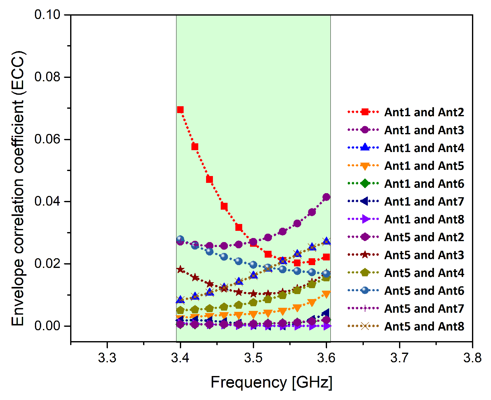
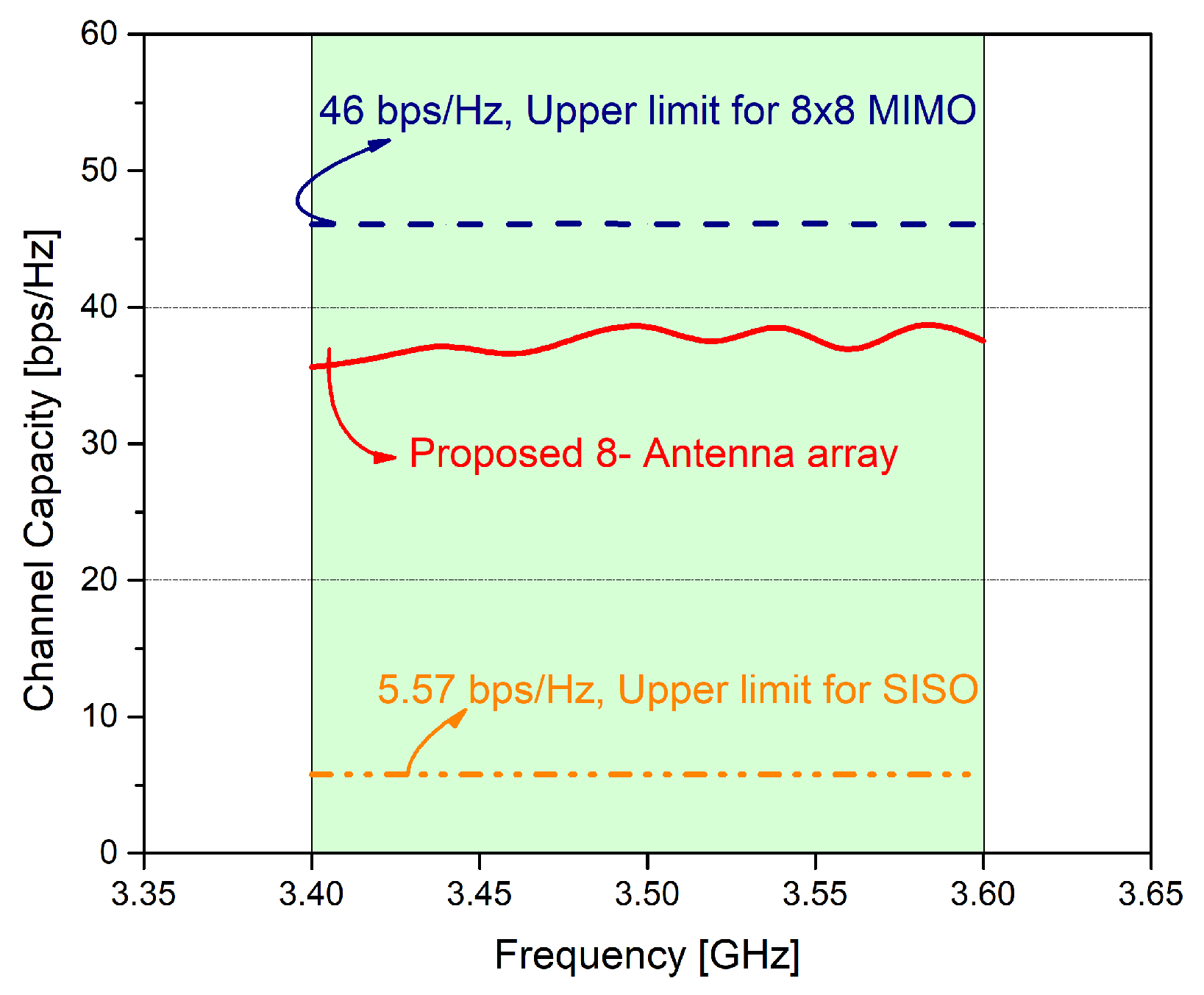
3.4. MIMO Parameters
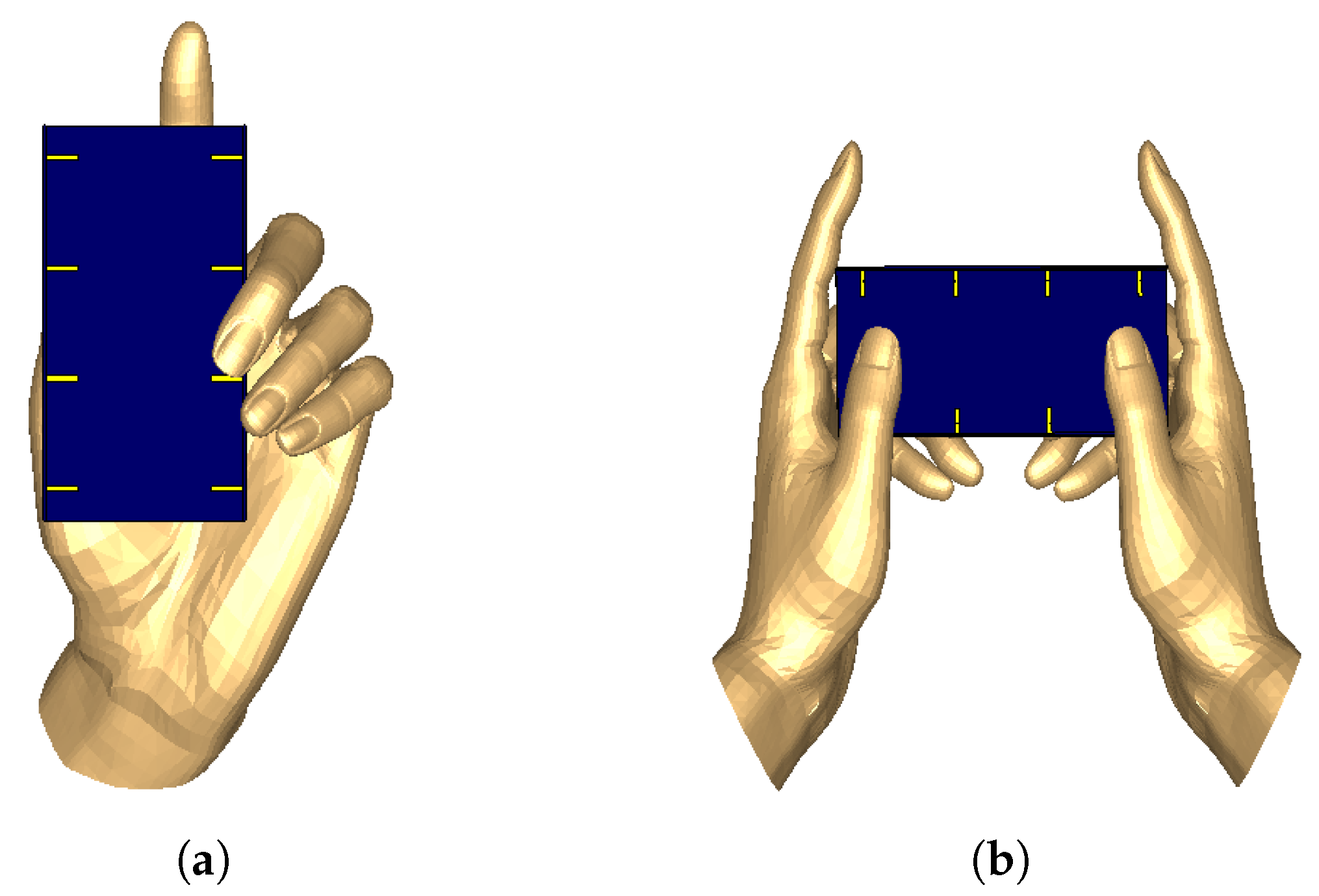
3.5. User Hand Effects
3.6. Liquid Crystal Display (LCD)
4. Conclusions
Author Contributions
Funding
Conflicts of Interest
References
- Ejaz, W.; Anpalagan, A.; Imran, M.A.; Jo, M.; Naeem, M.; Qaisar, S.B.; Wang, W. Internet of Things (IoT) in 5G Wireless Communications. IEEE Access 2016, 4, 10310–10314. [Google Scholar] [CrossRef]
- Minoli, D.; Occhiogrosso, B. Practical Aspects for the Integration of 5G Networks and IoT Applications in Smart Cities Environments. Wirel. Commun. Mob. Comput. 2019, 2019, 5710834. [Google Scholar] [CrossRef]
- Abdullah, M.; Kiani, S.H.; Abdulrazak, L.F.; Iqbal, A.; Bashir, M.; Khan, S.; Kim, S. High-performance multiple-input multiple-output antenna system for 5G mobile terminals. Electronics 2019, 8, 1090. [Google Scholar] [CrossRef]
- Hussain, R.; Alreshaid, A.T.; Podilchak, S.K.; Sharawi, M.S. Compact 4G MIMO antenna integrated with a 5G array for current and future mobile handsets. IET Microw. Antennas Propag. 2017, 11, 271–279. [Google Scholar] [CrossRef]
- Sehrai, D.A.; Abdullah, M.; Altaf, A.; Kiani, S.H.; Muhammad, F.; Tufail, M.; Irfan, M.; Glowacz, A.; Rahman, S. A Novel High Gain Wideband MIMO Antenna for 5G Millimeter Wave Applications. Electronics 2020, 9, 1031. [Google Scholar] [CrossRef]
- Altaf, A.; Alsunaidi, M.A.; Arvas, E. A novel EBG structure to improve isolation in MIMO antenna. In Proceedings of the 2017 USNC-URSI Radio Science Meeting (Joint with AP-S Symposium), San Diego, CA, USA, 9–14 July 2017; pp. 105–106. [Google Scholar]
- Lu, J.Y.; Chang, H.J.; Wong, K.L. 10-antenna array in the smartphone for the 3.6-GHz MIMO operation. In Proceedings of the 2015 IEEE International Symposium on Antennas and Propagation & USNC/URSI National Radio Science Meeting, Vancouver, BC, Canada, 19–24 July 2015; pp. 1220–1221. [Google Scholar]
- Deng, J.Y.; Yao, J.; Sun, D.Q.; Guo, L.X. Ten-element MIMO antenna for 5G terminals. Microw. Opt. Technol. Lett. 2018, 60, 3045–3049. [Google Scholar] [CrossRef]
- Li, M.Y.; Ban, Y.L.; Xu, Z.Q.; Guo, J.; Yu, Z.F. Tri-polarized 12-antenna MIMO array for future 5G smartphone applications. IEEE Access 2017, 6, 6160–6170. [Google Scholar] [CrossRef]
- Elshirkasi, A.M.; Al-Hadi, A.A.; Soh, P.J.; Mansor, M.F.; Khan, R.; Chen, X.; Akkaraekthalin, P. Performance Study of a MIMO Mobile Terminal with Upto 18 Elements Operating in the Sub-6 GHz 5G Band with User Hand. IEEE Access 2020, 8, 28164–28177. [Google Scholar] [CrossRef]
- Ali, T.; Alwadie, A.S.; Rizwan, A.R.; Sajid, A.; Irfan, M.; Awais, M. Moving towards IoT Based Digital Communication: An Efficient Utilization of Power Spectrum Density for Smart Cities. Sensors 2020, 20, 2856. [Google Scholar] [CrossRef]
- Li, R.; Mo, Z.; Sun, H.; Sun, X.; Du, G. A Low-Profile and High-isolated MIMO Antenna for 5G Mobile Terminal. Micromachines 2020, 11, 360. [Google Scholar] [CrossRef]
- Plonis, D.; Katkevičius, A.; Gurskas, A.; Urbanavičius, V.; Maskeliūnas, R.; Damaševičius, R. Prediction of Meander Delay System Parameters for Internet-of-Things Devices Using Pareto-Optimal Artificial Neural Network and Multiple Linear Regression. IEEE Access 2020, 8, 39525–39535. [Google Scholar] [CrossRef]
- Plonis, D.; Katkevičius, A.; Krukonis, A.; Šlegerytė, V.; Maskeliūnas, R.; Damaševičius, R. Predicting the frequency characteristics of hybrid meander systems using a feed-forward backpropagation network. Electronics 2019, 8, 85. [Google Scholar] [CrossRef]
- Li, Y.; Sim, C.Y.D.; Luo, Y.; Yang, G. High-Isolation 3.5 GHz Eight-Antenna MIMO Array Using Balanced Open-Slot Antenna Element for 5G Smartphones. IEEE Trans. Antennas Propag. 2019, 67, 3820–3830. [Google Scholar] [CrossRef]
- Huang, D.; Du, Z.; Wang, Y. Slot antenna array for fifth generation metal frame mobile phone applications. Int. J. Microw. Comput.-Aided Eng. 2019, 29, e21841. [Google Scholar] [CrossRef]
- Ren, A.; Liu, Y. A compact building block with two shared-aperture antennas for eight-antenna MIMO array in metal-rimmed smartphone. IEEE Trans. Antennas Propag. 2019, 67, 6430–6438. [Google Scholar] [CrossRef]
- Ojaroudi Parchin, N.; Jahanbakhsh Basherlou, H.; Alibakhshikenari, M.; Ojaroudi Parchin, Y.; Al-Yasir, Y.I.; Abd-Alhameed, R.A.; Limiti, E. Mobile-phone antenna array with diamond-ring slot elements for 5G massive MIMO systems. Electronics 2019, 8, 521. [Google Scholar] [CrossRef]
- Ojaroudi Parchin, N.; Jahanbakhsh Basherlou, H.; Al-Yasir, Y.I.; Abdulkhaleq, A.M.; Patwary, M.; Abd-Alhameed, R.A. A new CPW-Fed diversity antenna for MIMO 5G smartphones. Electronics 2020, 9, 261. [Google Scholar] [CrossRef]
- Sun, L.; Feng, H.; Li, Y.; Zhang, Z. Tightly arranged orthogonal mode antenna for 5G MIMO mobile terminal. Microw. Opt. Technol. Lett. 2018, 60, 1751–1756. [Google Scholar] [CrossRef]
- Zhao, A.; Ren, Z.; Wu, S. Broadband MIMO antenna system for 5G operations in mobile phones. Int. J. Microw. Comput.-Aided Eng. 2019, 29, e21857. [Google Scholar] [CrossRef]
- Wong, K.L.; Lu, J.Y.; Chen, L.Y.; Li, W.Y.; Ban, Y.L. 8-antenna and 16-antenna arrays using the quad-antenna linear array as a building block for the 3.5-GHz LTE MIMO operation in the smartphone. Microw. Opt. Technol. Lett. 2016, 58, 174–181. [Google Scholar] [CrossRef]
- Abdullah, M.; Ban, Y.L.; Kang, K.; Li, M.Y.; Amin, M. Eight-element antenna array at 3.5 GHz for MIMO wireless application. Prog. Electromagn. Res. 2017, 78, 209–216. [Google Scholar] [CrossRef]
- Iqbal, A.; A Saraereh, O.; Bouazizi, A.; Basir, A. Metamaterial-based highly isolated MIMO antenna for portable wireless applications. Electronics 2018, 7, 267. [Google Scholar] [CrossRef]
- Ding, Y.; Du, Z.; Gong, K.; Feng, Z. A novel dual-band printed diversity antenna for mobile terminals. IEEE Trans. Antennas Propag. 2007, 55, 2088–2096. [Google Scholar] [CrossRef]
- Kildal, P.S.; Rosengren, K. Correlation and capacity of MIMO systems and mutual coupling, radiation efficiency, and diversity gain of their antennas: Simulations and measurements in a reverberation chamber. IEEE Commun. Mag. 2004, 42, 104–112. [Google Scholar] [CrossRef]
- Wong, K.L.; Tsai, C.Y.; Lu, J.Y. Two asymmetrically mirrored gap-coupled loop antennas as a compact building block for eight-antenna MIMO array in the future smartphone. IEEE Trans. Antennas Propag. 2017, 65, 1765–1778. [Google Scholar] [CrossRef]
- Al-Hadi, A.A.; Ilvonen, J.; Valkonen, R.; Viikari, V. Eight-element antenna array for diversity and MIMO mobile terminal in LTE 3500 MHz band. Microw. Opt. Technol. Lett. 2014, 56, 1323–1327. [Google Scholar] [CrossRef]
- Jiang, W.; Liu, B.; Cui, Y.; Hu, W. High-isolation eight-element MIMO array for 5G smartphone applications. IEEE Access 2019, 7, 34104–34112. [Google Scholar] [CrossRef]
- Rao, L.Y.; Tsai, C.J. 8-Loop antenna array in the 5 inches size smartphone for 5G communication the 3.4 GHz–3.6 GHz band MIMO operation. In Proceedings of the 2018 Progress in Electromagnetics Research Symposium (PIERS-Toyama), Toyama, Japan, 1–4 August 2018; pp. 1995–1999. [Google Scholar]
- Zhao, A.; Ren, Z. Size reduction of self-isolated MIMO antenna system for 5G mobile phone applications. IEEE Antennas Wirel. Propag. Lett. 2018, 18, 152–156. [Google Scholar] [CrossRef]


| Component | Value (mm) | Component | Value (mm) |
|---|---|---|---|
| A1X | 2 | A1Y | 2.5 |
| A2X | 1 | A2Y | 14 |
| A3X | 1 | A3Y | 1.1 |
| A4X | 1 | A4Y | 4 |
| A5X | 1 | A5Y | 6 |
| A6X | 6 | A6Y | 1 |
| Frequency | MEG1 | MEG2 | MEG3 | MEG4 | MEG5 | MEG6 | MEG7 | MEG8 |
|---|---|---|---|---|---|---|---|---|
| 3.5GHz | −2.96 | −2.98 | −3.02 | −3.13 | −3.09 | −2.84 | −2.73 | −2.80 |
| Indoor | −4.98 | −5.02 | −5.45 | −5.89 | −6.23 | −6.15 | −5.43 | −6.31 |
| Refs | Bandwidth | Elements | Unit Size | Antenna | Channel | ECC |
|---|---|---|---|---|---|---|
| (GHz) | in mm (LxW) | Efficiency | Capacity | |||
| [18] | 3.4–3.6 | 8 | 5.25 × 3.9 | 60–80 | NA | 0.1 |
| (−10 dB) | (Planar) | |||||
| [23] | 3.4–3.6 | 8 | 10 × 2.5 | 40–60 | 37 | 0.2 |
| (−10 dB) | (Planar) | |||||
| [22] | 3.4–3.6 | 8 | 3 × 8 | 30–52 | 37 | 0.3 |
| (−6 dB) | (Planar) | |||||
| [27] | 3.4–3.6 | 8 | 16 × 5 | 40–52 | 35 | 0.15 |
| (−6 dB) | (Side-Edged) | |||||
| [28] | 3.4–3.6 | 8 | 12 × 12.5 | 58–72 | 15 | NA |
| (−6 dB) | (Planar) | |||||
| [29] | 3.3–3.6 | 8 | 10 × 4.3 | 40–60 | 37 | 0.1 |
| (−10 dB) | (Side-Edged) | |||||
| [30] | 3.4–3.6 | 8 | 14.2 × 9.4 | 30–50 | NA | 0.2 |
| (−6 dB) | (Planar) | |||||
| [31] | 3.4–3.6 | 8 | 17.4 × 6 | 50–60 | NA | 0.15 |
| (−10 dB) | (Side-Edged) | |||||
| Proposed | 3.25–3.65 | 8 | 14 × 6 | 58–72 | 38.5 | 0.1 |
| (−6 dB) | (Side-Edged) |
Publisher’s Note: MDPI stays neutral with regard to jurisdictional claims in published maps and institutional affiliations. |
© 2020 by the authors. Licensee MDPI, Basel, Switzerland. This article is an open access article distributed under the terms and conditions of the Creative Commons Attribution (CC BY) license (http://creativecommons.org/licenses/by/4.0/).
Share and Cite
Kiani, S.H.; Altaf, A.; Abdullah, M.; Muhammad, F.; Shoaib, N.; Anjum, M.R.; Damaševičius, R.; Blažauskas, T. Eight Element Side Edged Framed MIMO Antenna Array for Future 5G Smart Phones. Micromachines 2020, 11, 956. https://doi.org/10.3390/mi11110956
Kiani SH, Altaf A, Abdullah M, Muhammad F, Shoaib N, Anjum MR, Damaševičius R, Blažauskas T. Eight Element Side Edged Framed MIMO Antenna Array for Future 5G Smart Phones. Micromachines. 2020; 11(11):956. https://doi.org/10.3390/mi11110956
Chicago/Turabian StyleKiani, Saad Hassan, Ahsan Altaf, Mujeeb Abdullah, Fazal Muhammad, Nosherwan Shoaib, Muhammad Rizwan Anjum, Robertas Damaševičius, and Tomas Blažauskas. 2020. "Eight Element Side Edged Framed MIMO Antenna Array for Future 5G Smart Phones" Micromachines 11, no. 11: 956. https://doi.org/10.3390/mi11110956
APA StyleKiani, S. H., Altaf, A., Abdullah, M., Muhammad, F., Shoaib, N., Anjum, M. R., Damaševičius, R., & Blažauskas, T. (2020). Eight Element Side Edged Framed MIMO Antenna Array for Future 5G Smart Phones. Micromachines, 11(11), 956. https://doi.org/10.3390/mi11110956