Article

Liquid Refractive Index Measurement System Based on Electrowetting Lens

1
School of Instrumentation and Optoelectronic Engineering, Beihang University, Beijing 100191, China
2
College of Physics and Optoelectronics, Taiyuan University of Technology, Taiyuan 030024, China
3
Beijing Advanced Innovation Center for Big Data-based Precision Medicine, Beihang University, Beijing 100191, China
*
Author to whom correspondence should be addressed.
Micromachines 2019, 10(8), 515; https://doi.org/10.3390/mi10080515
Submission received: 30 June 2019 / Revised: 24 July 2019 / Accepted: 28 July 2019 / Published: 1 August 2019
(This article belongs to the Special Issue IMCO 2019)

Abstract

:
In this paper, a liquid refractive index (LRI) measurement system based on an electrowetting lens was proposed. The system is composed of a light source, a collimating lens, a liquid measurement chamber (LMC), an electrowetting lens and an image sensor, which is integrated into a cylindrical cavity. The refractive index of the LMC changes with the addition of the measured liquid, and the incident light cannot be focused on the image plane. By adjusting the driving voltage of the electrowetting lens, the curvature of the liquid-liquid interface changes to focus the incident light onto the image plane. The refractive index of the liquid could be measured according to the voltage value. The proposed LRI measurement system has no mechanical moving parts, and the imaging surface remains stationary, which can make the measurement simply and correctly. The experiments show that the refractive index measurement range of the system can be turned from ~1.3300 to ~1.4040, and the measurement accuracy is 10−4. The system can be used to measure the optical properties of liquids and has broad potential applications in chemical reagent detection and pharmaceutical testing.

1. Introduction

A refractive index is an important optical parameter of liquids. With the refractive index, the optical properties, the purity, dispersion and diffusion coefficient of the fluids can be analyzed [1,2]. Conventional liquid refractive index (LRI) measurement systems can be classified into refractometers and interferometers, according to measurement methods [3,4,5,6]. The principle of the refractometer is based on the phenomenon of refraction or reflection generated by light passing through the surface of the liquid. Then the refractive index is measured according to the law of refraction or reflection. The grazing incidence method and laser irradiation method [7] are the typical methods. These measurement methods are relatively simple. However, the liquid in the measurement system is usually in contact with air, and is not suitable for measuring volatile and toxic liquids [7,8,9,10,11]. The most common refractometer is the Abbe refractometer (AR) [8], which is based upon the principle of total reflection. The advantages of AR are high precision, and it can read the value of the refractive index directly from the dial screen. However, AR has a large volume and complex operation. The interferometer employs the wave property of light to interfere or diffract with the determinant in order to measure the refractive index. Representative measurement methods are fiber, Young’s interferometry [9] and CCD measurement methods [10]. Unfortunately, the instruments based on the wave measurement methods are generally complicated. The operating system is usually cumbersome, and it also needs more liquids usage [7,8,9,10,11]. Thus, it is not suitable for the measurement of precious liquids.
Based on the above discussion, an LRI measurement system, which is economical, simple to operate, accurate in measurement, and not limited by the characteristics of the liquid, is highly desired.
In recent years, liquid optical devices have attracted the wide attention of researchers because of the unique advantages of small size, low cost, fast response time and high light transmittance. Some methods for measuring the refractive index of liquids using optical flow control devices have also been studied [12,13,14,15,16,17]. Among them, liquid lenses are widely used in measurement systems, due to the performance of adaptive zoom than the conventional solid lenses, such as the adaptive optical zoom system and the imaging system [18,19,20,21,22,23,24,25]. As far as we know, there are currently only two research groups that use liquid lenses to measure the refractive index. In 2012, Calixto et al. proposed a refractive index measurement through image analysis with an optofluidic lens [26]. The test solution is injected into a hollow lens made of Polydimethylsiloxane (PDMS). The light passing through the hollow lens forms a bright line on the image surface. The LRI can be tested by analyzing the visibility of the image. However, the hollow lens made of PDMS has not designed an inlet or outlet, which is not conducive to measure the refractive index of the liquid continuously. Moreover, the texture of PDMS is soft, and can be deformed or broken easily. In 2014, Cheng et al. also proposed a refractive index measurement by prism auto collimation [27], which can measure the refractive index of solids and liquids. However, the measurement system is complicated by the use of more optical components.
In this paper, a novel LRI measurement system based on an electrowetting lens was proposed. When different measured liquids are injected into the measuring cavity, the image planes will show the unfocused light spots. By adjusting the external driving voltage of the electrowetting lens, the spot will focus on the image plane, and the refractive index of the liquid can be calculated according to the applied voltage value. Compared with the previous works, the liquid measurement chamber (LMC) in the proposed system is small in volume and sealed by a cavity. Thus, both a precious liquid and a volatile liquid can be measured. Besides, the electrowetting lens has the advantages of small volume and adjustable focus. The proposed system does not need to move any mechanical component during the measurement. Moreover, the proposed system is simple to operate and can directly derive the LRI using the values of the driving voltage. In summary, the proposed system has the advantages of small size, high integration, convenient carrying, simple operation, no restriction on liquid characteristics, and no mechanical moving parts.

2. Structure and Operating Principle

2.1. Structure and Mechanism of the System

Figure 1 shows the structure and mechanism of the proposed system. The light emitting diode (LED) light source, the collimating lens, the LMC, the electrowetting lens and the image sensor are assembled in a cavity, wherein the LMC has two channels for convenience to inject liquids and clean the cavity, as shown in Figure 1a. In the initial state, the measured liquid is injected into the LMC, and the LED light passing through the collimator lens becomes a parallel beam. The parallel beam is deflected by the LMC, and the deflected light passes through the electrowetting lens to reach the image sensor to form a divergent light spot. Then, the light is focused on the image plane by adjusting the drive voltage of the electrowetting lens, as shown in Figure 1b,c. We can get the curvature of the electrowetting lens by the voltage value, and calculate the LRI according to the ‘yun’ ray-tracing method.

2.2. Theory of the Proposed System

As shown in Figure 2, the distance between the two optical lenses constituting the LMC is t, the refractive indices are n1 and n2, and the radii of curvature are C1 and C2, respectively. The refractive indices of the two filling liquids of the electrowetting lens are n3 and n4. The radius of curvature of the liquid contact surface is C3. The distance between the center of the liquid measurement chamber and the center of the electrowetting lens is d. The back focal length of the entire measurement system is B. According to the ‘yun’ ray-tracing method in geometric optics, it can be deduced that the liquid measurement cavity power φa and the electrowetting lens power φb can be calculated by Equations (1) and (2), respectively.
φa = 1/fa = (nxn1) C1 + (n2nx) C2 − [(nxn1) (n2nx) tC1C2]/nx
φb = 1/fb = (n4n3) C3
The back focal length of the entire measurement system is B, which can be expressed as:
B = (1 − a)/(φa + φbφaφbd)
In summary, the refractive index nx of the measured liquid is a function of the following parameters, namely:
nx = f (t, d, B, n1, n2, n3, n4, C1, C2, C3)
Among them, C1, C2, n1, n2, n3 and n4 are known quantities; t, d and B can be directly measured, C3 can be measured according to the curvature of the electrowetting lens and the values of the driving voltage. Through the above formulas, the refractive index of the measured liquid can be calculated.

2.3. Fabrication of the Proposed System

The cavity of the LRI measurement instrument and other implements are fabricated by a 3D printer. The outer diameter and the inner diameter of the cavity are 18 mm and 10 mm, respectively, and the length is about 70 mm. The inlet and outlet with the same diameter of 1 mm are symmetrically distributed on the LMC. The collimating lens is made of BK7 optical glass with a radius of curvature of 50 mm. The LMC consists of two flat-concave lenses. The lenses are made of K9 optical glass with a radius of curvature of 150 mm, the center thickness of each convex lens is 1.5 mm, and the distance between the two convex lenses is 4 mm. The electrowetting lens is an Arctic-39N0 developed by Corning Inc. (New York, NY, USA) The distances between the LED, the collimating lens, the liquid measurement chamber, the electrowetting lens and the image sensor are 7 mm, 10 mm, 25 mm, 25 mm, respectively. The components of the LRI measurement system are shown in Figure 3.

3. Experiments and Discussion

3.1. Experiment of the Proposed System

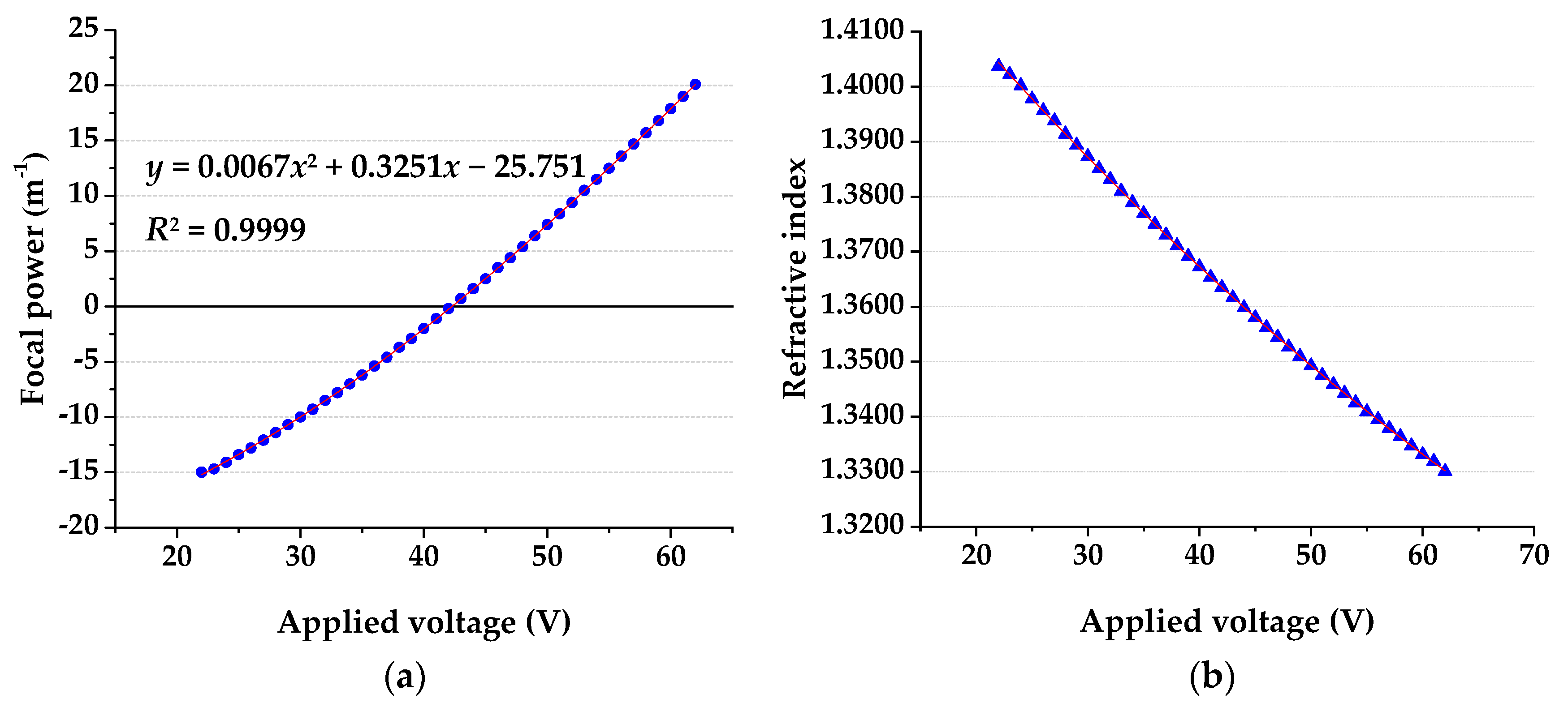
The electrowetting lens is an essential component of the liquid refractive index meter system. It should be noted that the external driving voltage adjustment of the electrowetting lens is realized by a computer software operating a driving board connected to the computer. The values of the focal power corresponding to the different driving voltages of the electrowetting lens is shown in Figure 4a. At the same time, the relation is also fitted to the curve: y = 0.0067x2 + 0.3251x − 25.751 (R2 = 0.9999).
According to the formula in Section 2.2, the relationship between the driving voltage and the refractive index is calculated, as shown in Figure 4b.
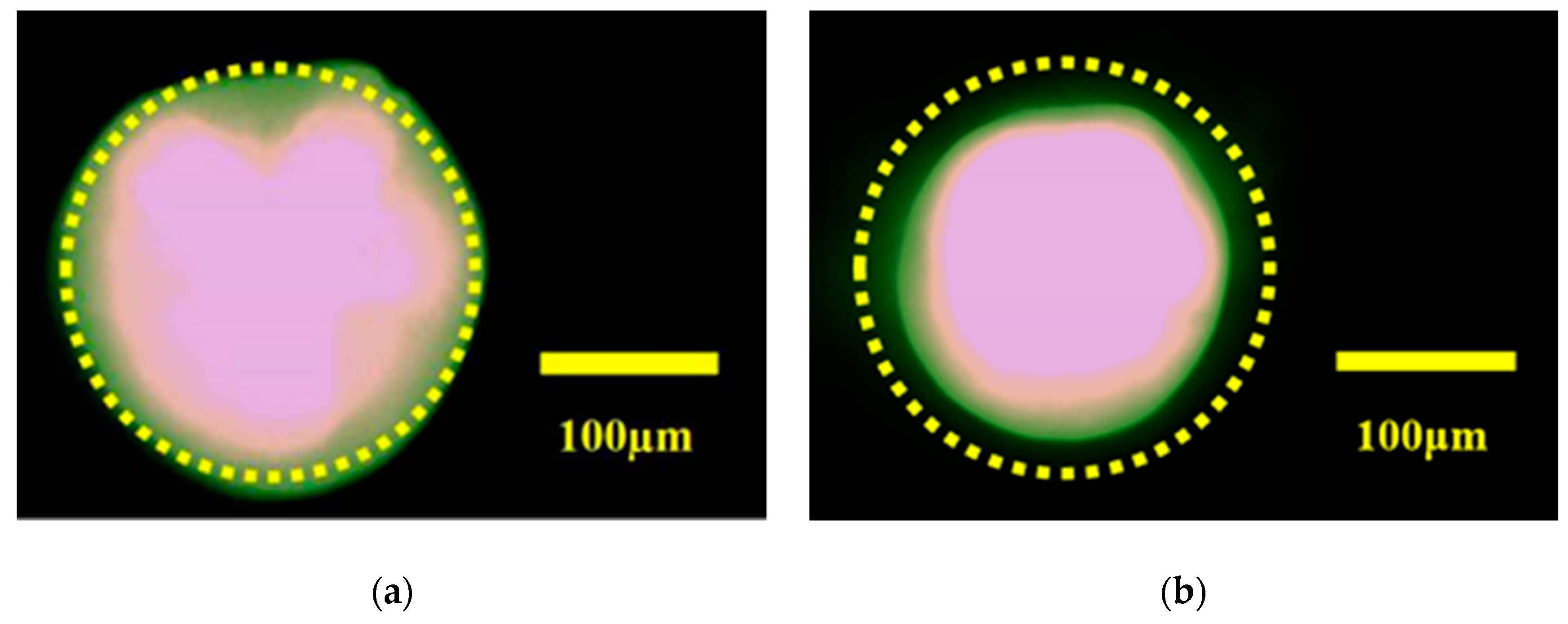
We assembled the components and set up the measurement system according to Section 2.3, and measured the refractive index of a 10% NaCl solution. First, a 10% NaCl solution is injected into the LMC. The light from the LED passes through the collimating lens, the LMC and the electrowetting lens, and reaches the image plane to form a divergent spot, as shown in Figure 5a. Then, we adjust the applied driving voltage of the electrowetting lens. When the applied voltage is increased from 0 V to 49 V, the spot diameter gradually becomes smaller. When the driving voltage reaches 50 V, the spot becomes larger than before. Therefore, when the applied driving voltage is 49 V, the spot is minimized on the image plane, as shown in Figure 5b. According to the data of Figure 4b, the refractive index of 10% NaCl is 1.3509. Compared with the reported value 1.3515, the error is −0.0444. The experimental results show that the LRI measurement system can measure the refractive index of the liquid correctly, and its measurement accuracy is 104.
Based on the above experiments, the refractive indices of different concentrations of NaCl solution were measured according to the above experimental procedures. The measurement results are shown in Table 1.
The experimental results show that the refractive index of the NaCl solution becomes larger as the concentration increases, and the applied driving voltages of the electrowetting lens decrease as the refractive indices increase. The average error of the theoretical and practical measurements is −0.0207.
Besides, we have characterized the proposed liquid refractive index measurement system using the Brix standard. The concentration of sucrose solutions was measured, as shown in Table 2. As can be seen, when the sucrose solution concentration is 42%, the applied driving voltage of the electrowetting lens reaches the limit value of 22 V. So, the system can measure the concentration of the sucrose solution in the range from ~0% to ~42%, that is, the range of Brix is ~0% to ~42%, and the corresponding refractive index range is ~1.3300 to ~1.4040.
To further analyze the error of the system, we also measured the refractive index of distilled water (DW), ethanol and isopropanol with a known refractive index. The measurement results and errors are shown in Table 3. From the measurement results, the proposed system can measure the refractive index of a liquid correctly.
According to the experimental results, the liquid refractive index (LRI) measurement system based on the electrowetting lens can provide a reliable method to measure the refractive index of liquid correctly, and its accuracy is 10−4.

3.2. Discussion

The key novelty of the LRI measurement system is that it can easily measure the LRI directly by adjusting the applied voltage without any moving mechanical parts. The system can be used within areas where it is necessary to measure the refractive index of liquids simply and quickly. However, some of the performance of this system can also be improved. As can be seen from Figure 4b, the LRI measurement range of the system herein is about 1.3300~1.4040, which is smaller than that of the conventional method using the Abbe refractometer (1.3300–1.7000).
The reason may be that the LMC used in the system consists of two planoconvex lenses, which we can consider as cylindrical lenses. When a liquid with a broad refractive index is measured, the focal length of the cylindrical lens is significantly increased, thereby exceeding the zooming ability of the electrowetting lens.
To solve this issue, we can change the structure of the LMC to expand the range of the refractive index of the liquid. As shown in Figure 6, the LMC is composed of a convex lens and a flat glass, which are 4 mm apart and are made of K9 optical glass. The two surfaces of the convex lens have curvatures of 15 and −30, respectively. The center thickness of the convex lens is 1.5 mm. The thickness of the flat glass is 1.5 mm. Under this structure, the liquid measurement range can be extended to 1.3300–1.7000.
Besides, the accuracy of the LRI measurement system proposed in this paper is 10−4, which is lower than the accuracy of the prism-based refractive index measurement system by 10−6. One of the reasons is that the applied driving voltage of the electrowetting lens is incremented by 1 V. The relationship between the driving voltage and the refractive index is nonlinear, which affects the measurement accuracy of the system and causes measurement errors. But if the drive voltage increment could be reduced to 0.5 V, the accuracy of the liquid refractive index would be significantly improved, and the measurement errors would also be reduced accordingly.
At last, another error source of the LRI measurement system was analyzed, and the corresponding solutions were proposed. When a plurality of sample liquids is continuously measured for their respective refractive indices, the fluids may remain in the LMC, so that mixing with different liquids may cause an inaccurate refractive index measurement. However, when processing the LMC, we can spin-coat a layer of Teflon hydrophobic coating on the inner wall which can significantly reduce the possibility of liquid residue in the LMC and improve the accuracy of the measurement.

4. Conclusions

In this paper, an LRI measurement system based on an electrowetting lens was proposed. The system can measure the refractive index of different liquids continuously by adjusting the applied driving voltage of the electrowetting lens without moving any mechanical components. The proposed LRI measurement system has the advantages of simple operation, small size and portability. The system can be used to measure the optical properties of liquids, and has the potential to be widely used in the fields of the chemical and the food industries. Experimental results show that the measurement range of the system can be turned from ~1.3300 to ~1.4040, and the system measurement accuracy is 10−4. In later work, we will further optimize the structure of the system, expand the measurement range of the liquid refractive index, and improve the measurement accuracy.

Author Contributions

Conceptualization, C.L. and S.-L.L.; methodology, Z.-Q.N.; data curation, Y.-T.T.; writing—original draft preparation, S.-L.L.; writing—review and editing, C.L. and Z.-Q.N.

Funding

This research was funded by the National Natural Science Foundation of China under Grant No. 61805169, 61805130 and 51602213; China Postdoctoral Science Foundation under Grant No. 2019M650421 and 2019M650422.

Conflicts of Interest

The authors declare no conflict of interest. The funders had no role in the design of the study; in the collection, analyses, or interpretation of data; in the writing of the manuscript, or in the decision to publish the results.

References

  1. Yan, X.; Li, B.; Cheng, T.L.; Li, S.G. Analysis of high sensitivity photonic crystal fiber sensor based on surface plasmon resonance of refractive indexes of liquids. Sensors 2018, 18, 2922. [Google Scholar] [CrossRef] [PubMed]
  2. Syed, M.B. Analysis of biodiesel by high performance liquid chromatography using refractive index detector. Methods X 2017, 4C, 256–259. [Google Scholar] [CrossRef] [PubMed]
  3. Rheims, J.; Köser, J.; Wriedt, T. Refractive-index measurements in the near-IR using an Abbe refractometer. Meas. Sci. Technol. 1999, 8, 601. [Google Scholar] [CrossRef]
  4. Takeo, T.; Hattori, H. Optical fiber sensor for measuring refractive index. Jpn. J. Appl. Phys. 1982, 21, 1509. [Google Scholar] [CrossRef]
  5. Tai, Y.H.; Wei, P.K. Sensitive liquid refractive index sensors using tapered optical fiber tips. Opt. Lett. 2010, 35, 944–946. [Google Scholar] [CrossRef] [PubMed]
  6. Roth, N.; Klaus, A.; Arnold, F. Refractive-index measurements for the correction of particle sizing methods. Appl. Opt. 1991, 30, 4960–4965. [Google Scholar] [CrossRef] [PubMed]
  7. Singh, S. Measuring the refractive index of a liquid using a laser. Phys. Educ. 2002, 37, 152–153. [Google Scholar] [CrossRef]
  8. Wenzel, R.G.; Arnold, G.P. Measurement of refractive index of small liquid specimens in capillaries. Rev. Sci. Inst. 1969, 40, 1355–1360. [Google Scholar] [CrossRef]
  9. Sun, J.H.; Wang, M. Measuring the refractive index of liquid by optical fiber Young’s interference experiment. Phys. Exp. Coll. 2005, 18, 8–10. [Google Scholar]
  10. Deng, G.A.; Cai, Z.; Zhang, Y.; Xu, Y.; Wu, S.; Zhou, J. Refraction index measurement of transparent materials by using diffraction grating and CCD. Acta Opt. Sin. 2004, 24, 99–103. [Google Scholar]
  11. Shyam, S. Diffraction method measures refractive indices of liquids. Phys. Educ. 2004, 39, 235. [Google Scholar]
  12. Domachuk, P.; Littler, I.C.M.; Golomb, M.C.; Eggleton, B.J. Compact resonant integrated microfluidic refractometer. Appl. Phys. Lett. 2006, 88, 093513. [Google Scholar] [CrossRef]
  13. Campopiano, S.; Bernini, R.; Zeni, L.; Sarro, P.M. Microfluidic sensor based on integrated optical hollow waveguides. Opt. Lett. 2004, 29, 1894–1896. [Google Scholar] [CrossRef] [PubMed]
  14. Polynkin, P.; Polynkin, A.; Peyghambarian, N.; Mansuripur, M. Evanescent field-based optical fiber sensing device for measuring the refractive index of liquids in microfluidic channels. Opt. Lett. 2007, 30, 1273–1275. [Google Scholar] [CrossRef] [PubMed]
  15. Xu, F.; Horak, P.; Brambilla, G. Optical microfiber coil resonator refractometric sensor. Opt. Express 2007, 15, 7888–7893. [Google Scholar] [CrossRef] [PubMed]
  16. Calixto, S.; Aguilar, M.R.; Hernandez, D.M.; Minkovich, V.P. Capillary refractometer integrated in a microfluidic configuration. Appl. Opt. 2008, 47, 843–848. [Google Scholar] [CrossRef] [PubMed]
  17. Chen, M.H.; Jia, W.Y.; He, J.T.; Martial, G.; Zheng, G. A miniaturized system for measurement of the refractive index of sub-microliter liquid. Chin. Opt. Lett. 2019, 17, 51–55. [Google Scholar]
  18. Liu, C.; Wang, D.; Wang, Q.H. Variable aperture with graded attenuation combined with adjustable focal length lens. Opt. Express 2019, 27, 14075–14084. [Google Scholar] [CrossRef]
  19. Murade, C.U.; Oh, J.M.; Ende, D.V.D.; Mugele, F. Electrowetting driven optical switch and tunable aperture. Opt. Express 2011, 19, 15525–15531. [Google Scholar] [CrossRef]
  20. Ren, H.; Xu, S.; Ren, D.; Wu, S.T. Novel optical switch with a reconfigurable dielectric liquid droplet. Opt. Express 2011, 19, 1985–1990. [Google Scholar] [CrossRef]
  21. Ren, H.; Xu, S.; Liu, Y.F.; Wu, S.T. Liquid-based infrared optical switch. Appl. Phys. Lett. 2012, 101, 041104. [Google Scholar] [CrossRef]
  22. Liu, C.; Li, L.; Wang, D.; Yao, L.X.; Wang, Q.H. Liquid optical switch based on total internal reflection. IEEE Photonics Technol. Lett. 2015, 27, 2091–2094. [Google Scholar] [CrossRef]
  23. Liu, C.; Wang, Q.H.; Wang, M.H.; Yao, L.X. Optical switch matrix based on a liquid-actuated mirror reflector. Opt. Eng. 2014, 53, 117107. [Google Scholar] [CrossRef]
  24. Liu, C.; Wang, D.; Wang, Q.H.; Fang, J.C. Electrowetting-actuated multifunctional optofluidic lens to improve the quality of computer-generated holography. Opt. Express 2019, 27, 12963–12975. [Google Scholar] [CrossRef] [PubMed]
  25. Wang, D.; Wang, Q.H.; Shen, C.; Zhou, X.; Liu, C.M. Active optical zoom system. Appl. Opt. 2014, 53, 7402. [Google Scholar] [CrossRef]
  26. Calixto, S.; Aguilar, M.R.; Marin, F.J.S.; Solano, M.C.; Mariscal, C.L. Refractive index measurement through image analysis with an optofluidic device. Opt. Express 2012, 20, 2073–2080. [Google Scholar] [CrossRef]
  27. Cheng, C.C. Refractive index measurement by prism autocollimation. Am. J. Phys. 2014, 82, 214–216. [Google Scholar] [CrossRef]
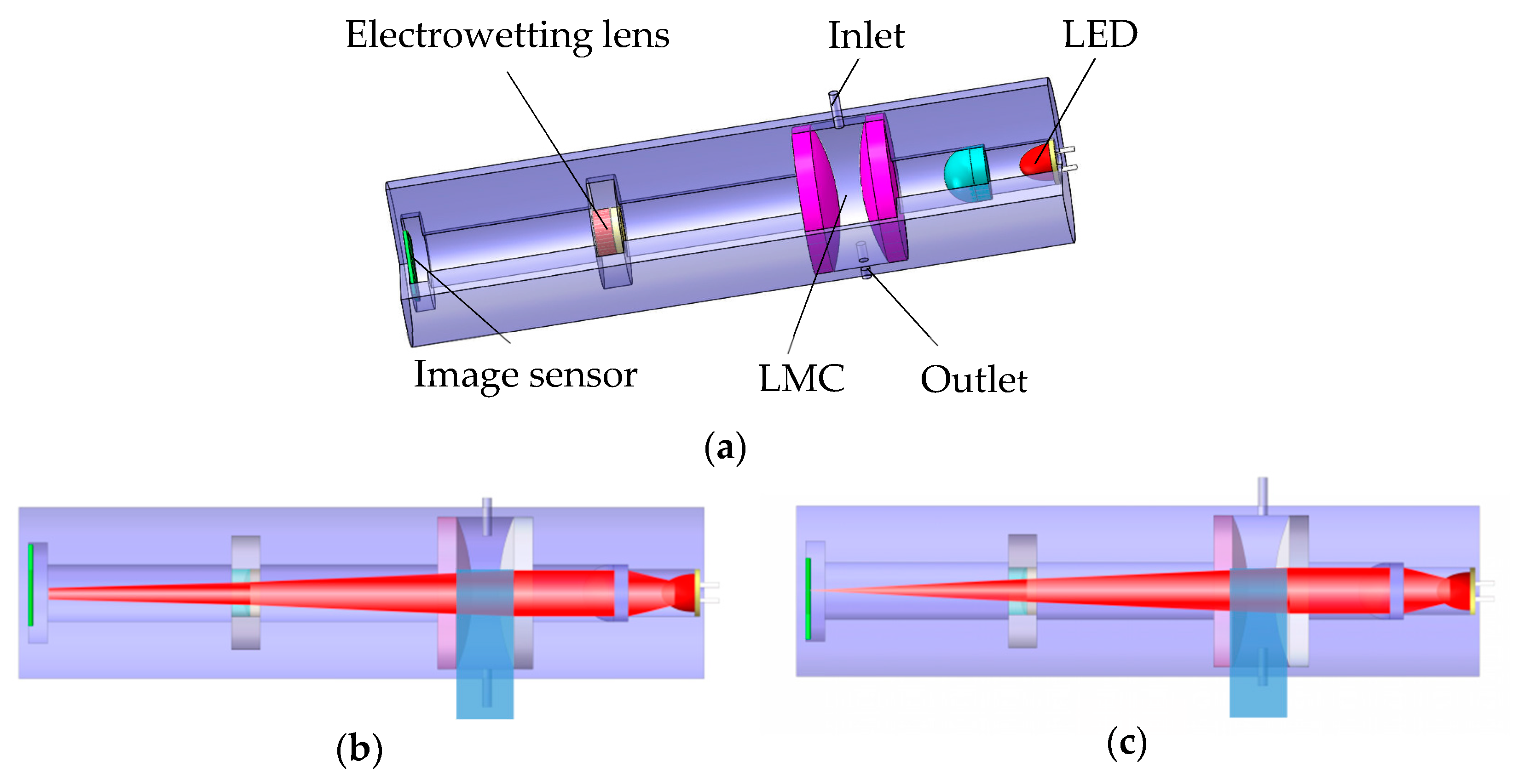
Figure 1. Structure and mechanism of the proposed system. (a) Cross-section of the system. (b) State of voltage off. (c) State of voltage on. (Where LMC is the liquid measurement chamber and LED refers to the light emitting diode).
Micromachines 10 00515 g001
Figure 2. Mathematical model of the system.
Micromachines 10 00515 g002
Figure 3. Components of the proposed system.
Micromachines 10 00515 g003
Figure 4. (a) Focal power of an electrowetting lens under different applied voltages. (b) Refractive index under different applied voltages.
Micromachines 10 00515 g004
Figure 5. (a) Light spot under the state of voltage off. (b) Light spot under the state of voltage on.
Micromachines 10 00515 g005
Figure 6. Structural simulation with different refractive indices. (a) Refractive index 1.3300 @ voltages of 62 V. (b) Refractive index 1.7000 @ voltages of 22 V.
Micromachines 10 00515 g006
Table 1. Refractive index and error measurement with different concentrations of NaCl solution.
Concentration of NaCl Solution (%)Refractive Index in the LiteratureMeasured Refractive IndexError (%)Applied Voltage (V)
11.33471.3346−0.007559
51.34281.3425−0.022354
101.35151.3509−0.044449
151.36031.3598−0.036844
201.37091.37100.007338
Table 2. Refractive index with different concentrations of sucrose solution.
Sucrose Solution Concentration (%)Measured Refractive IndexApplied Voltage (V)
51.340955
101.347551
201.363542
301.383132
401.400224
411.402223
421.404022
Table 3. Refractive index and error measured with different liquids.
LiquidDWEthanol (50%)IsopropanolAlcohol
Refractive index in the literature1.33301.35901.37501.3900
Measured refractive index1.33301.35981.37491.3893
Error (%)0.00980.05930.00010.0464
Applied voltage (V)62443629