Two-Dimensional Manipulation in Mid-Air Using a Single Transducer Acoustic Levitator


Abstract
1. Introduction
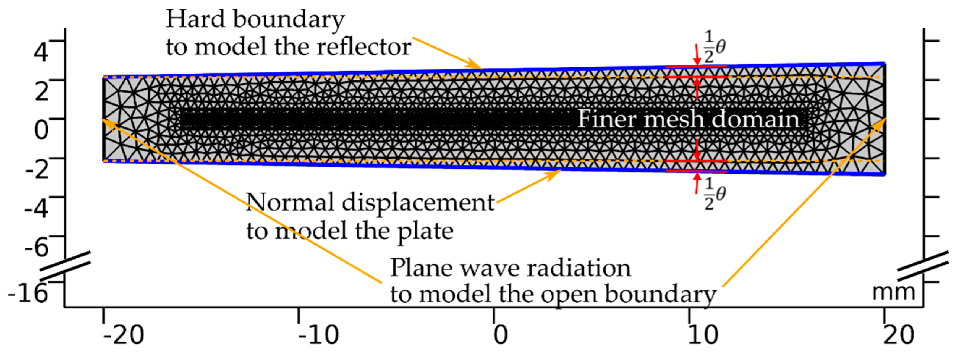
2. Methods
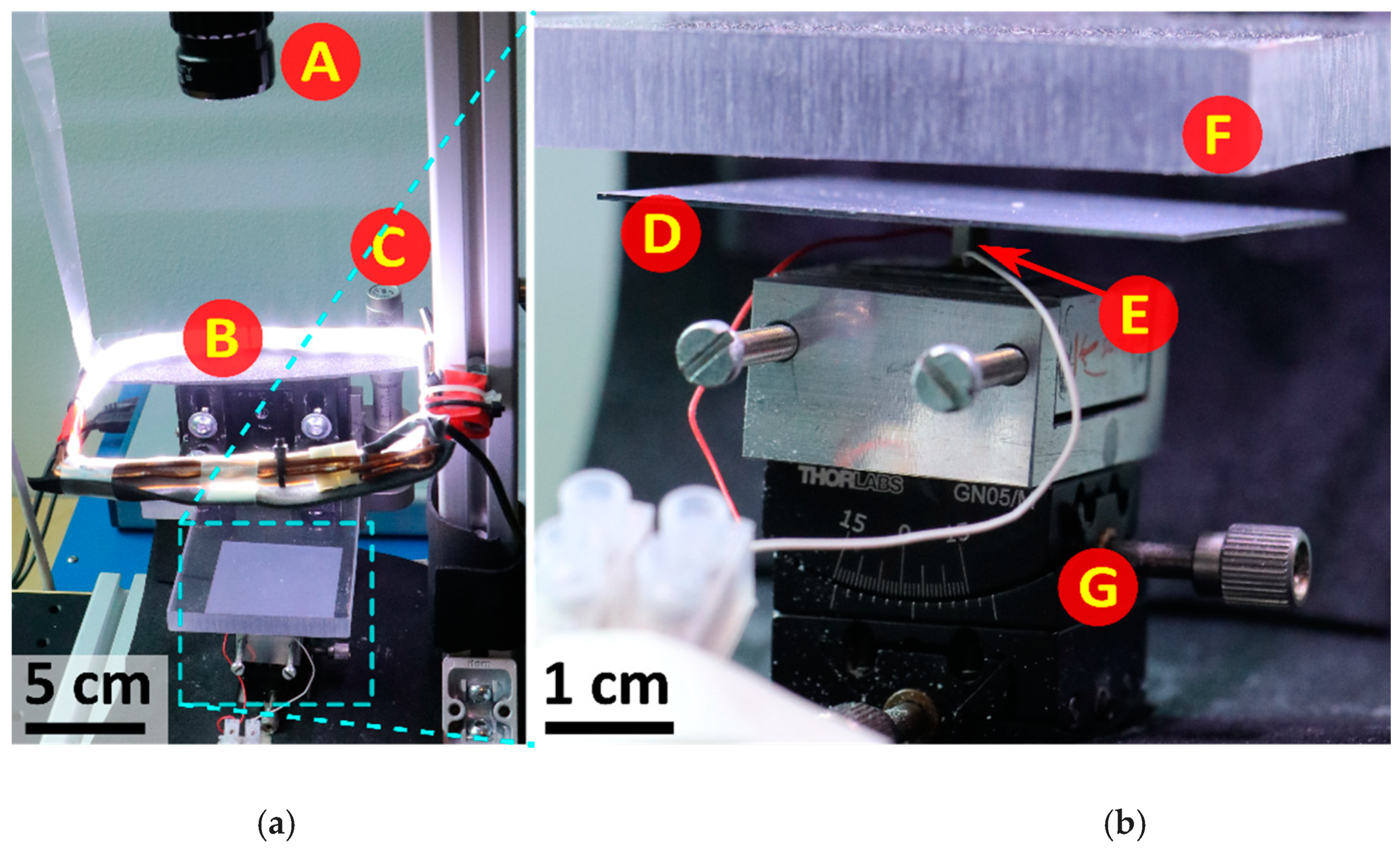
2.1. Experimental Setup and Material
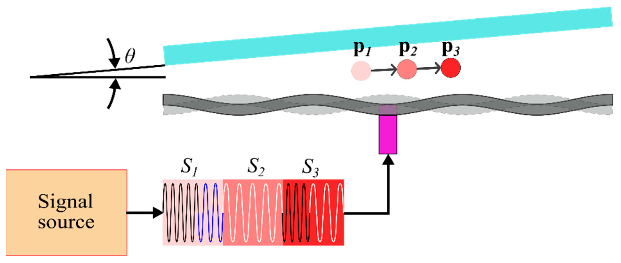
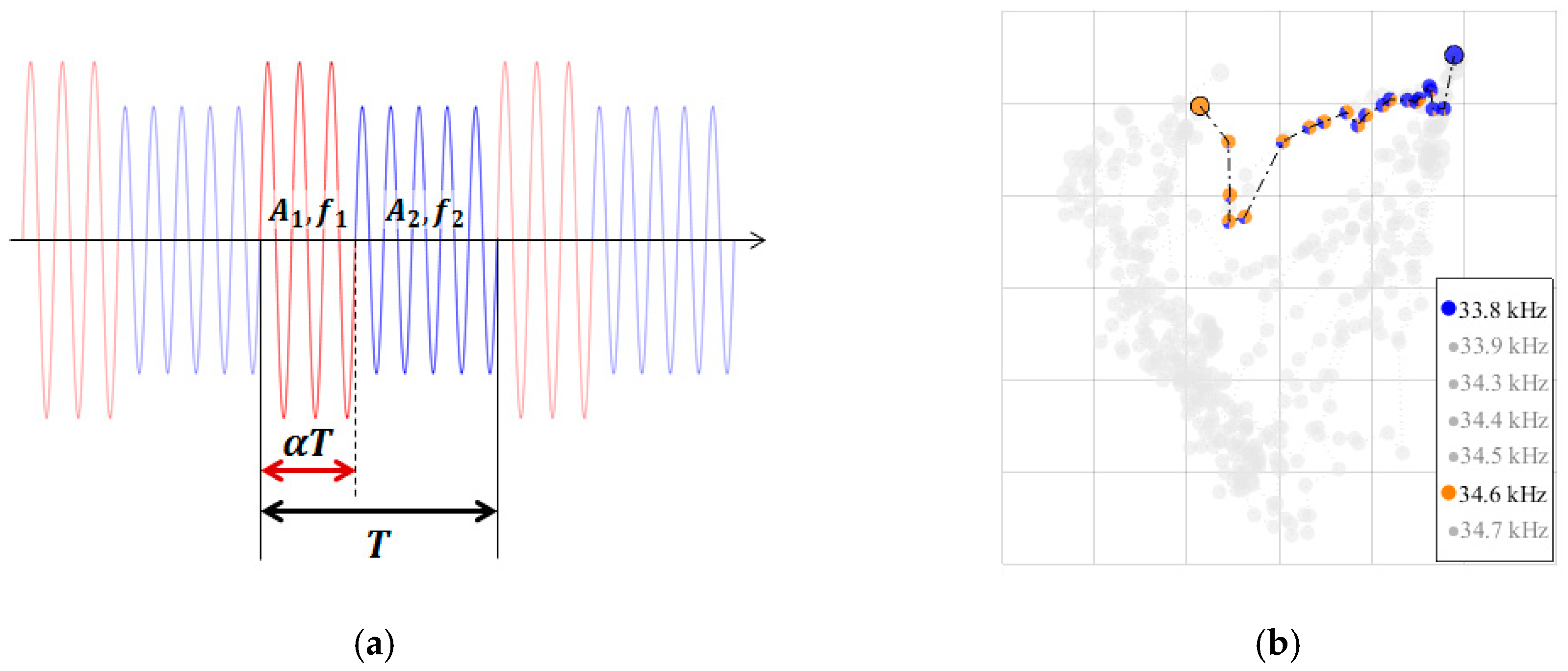
2.2. Manipulation Method
3. Results and Discussion
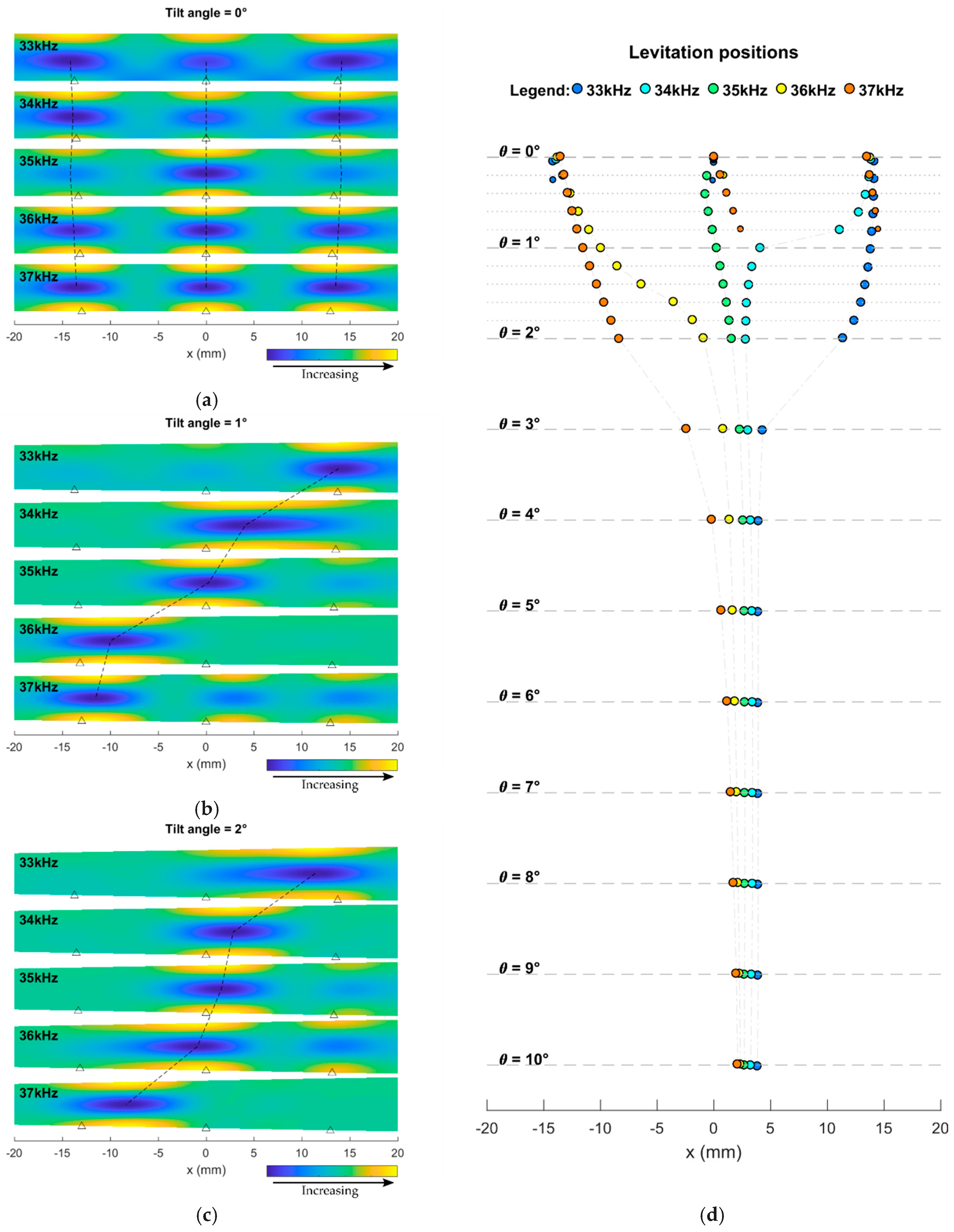
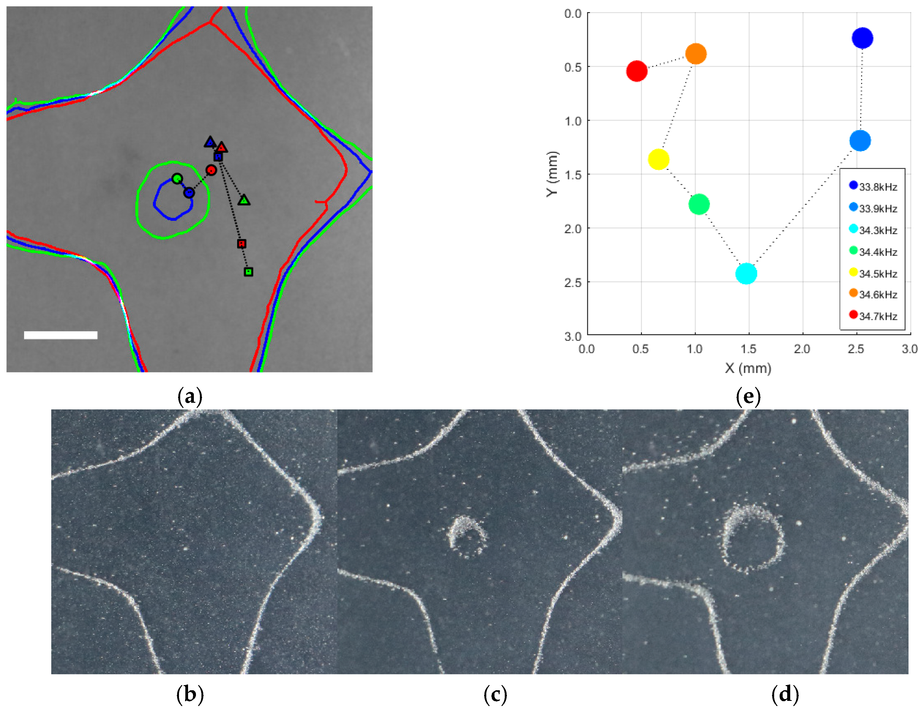
3.1. Maps of Levitation Position versus Vibrating Frequency
3.2. Establish New Levitation Positions by Frequency-Switching
3.3. Trajectory Following Demonstration
4. Conclusions
Supplementary Materials
Author Contributions
Acknowledgments
Conflicts of Interest
References
- Jonnalagadda, U.S.; Hill, M.; Messaoudi, W.; Cook, R.B.; Oreffo, R.O.C.; Glynne-Jones, P.; Tare, R.S. Acoustically modulated biomechanical stimulation for human cartilage tissue engineering. Lab Chip 2018, 18, 473–485. [Google Scholar] [CrossRef] [PubMed]
- Bouyer, C.; Chen, P.; Güven, S.; Demirtaş, T.T.; Nieland, T.J.F.; Padilla, F.; Demirci, U. A Bio-Acoustic Levitational (BAL) Assembly Method for Engineering of Multilayered, 3D Brain-Like Constructs, Using Human Embryonic Stem Cell Derived Neuro-Progenitors. Adv. Mater. 2016, 28, 161–167. [Google Scholar] [CrossRef]
- Chen, Z.; Zang, D.; Zhao, L.; Qu, M.; Li, X.; Li, X.; Li, L.; Geng, X. Liquid Marble Coalescence and Triggered Microreaction Driven by Acoustic Levitation. Langmuir 2017, 33, 6232–6239. [Google Scholar] [CrossRef]
- Crawford, E.A.; Esen, C.; Volmer, D.A. Real Time Monitoring of Containerless Microreactions in Acoustically Levitated Droplets via Ambient Ionization Mass Spectrometry. Anal. Chem. 2016, 88, 8396–8403. [Google Scholar] [CrossRef] [PubMed]
- Alghane, M.; Chen, B.X.; Fu, Y.Q.; Li, Y.; Luo, J.K.; Walton, A.J. Experimental and numerical investigation of acoustic streaming excited by using a surface acoustic wave device on a 128° YX-LiNbO3 substrate. J. Micromech. Microeng. 2011, 21, 015005. [Google Scholar] [CrossRef]
- Zhou, Q.; Sariola, V.; Latifi, K.; Liimatainen, V. Controlling the motion of multiple objects on a Chladni plate. Nat. Commun. 2016, 7, 12764. [Google Scholar] [CrossRef]
- Latifi, K.; Wijaya, H.; Zhou, Q. Multi-particle acoustic manipulation on a Chladni plate. In Proceedings of the 2017 International Conference on Manipulation, Automation and Robotics at Small Scales (MARSS), Montreal, QC, Canada, 17–21 July 2017. [Google Scholar]
- Collins, D.J.; Khoo, B.L.; Ma, Z.; Winkler, A.; Weser, R.; Schmidt, H.; Han, J.; Ai, Y. Selective particle and cell capture in a continuous flow using micro-vortex acoustic streaming. Lab Chip 2017, 17, 1769–1777. [Google Scholar] [CrossRef]
- Zhang, S.P.; Lata, J.; Chen, C.; Mai, J.; Guo, F.; Tian, Z.; Ren, L.; Mao, Z.; Huang, P.H.; Li, P.; et al. Digital acoustofluidics enables contactless and programmable liquid handling. Nat. Commun. 2018, 9, 1–11. [Google Scholar] [CrossRef] [PubMed]
- Goldowsky, J.; Mastrangeli, M.; Jacot-Descombes, L.; Gullo, M.R.; Mermoud, G.; Brugger, J.; Martinoli, A.; Nelson, B.J.; Knapp, H.F. Acousto-fluidic system assisting in-liquid self-assembly of microcomponents. J. Micromech. Microeng. 2013, 23, 125026. [Google Scholar] [CrossRef]
- Marzo, A.; Drinkwater, B.W. Holographic acoustic tweezers. Proc. Natl. Acad. Sci. 2018, 116, 84–89. [Google Scholar] [CrossRef]
- Watanabe, A.; Hasegawa, K.; Abe, Y. Contactless Fluid Manipulation in Air: Droplet Coalescence and Active Mixing by Acoustic Levitation. Sci. Rep. 2018, 8, 10221. [Google Scholar] [CrossRef]
- Foresti, D.; Nabavi, M.; Klingauf, M.; Ferrari, A.; Poulikakos, D. Acoustophoretic contactless transport and handling of matter in air. Proc. Natl. Acad. Sci. USA 2013, 110, 12549–12554. [Google Scholar] [CrossRef]
- Marzo, A.; Seah, S.A.; Drinkwater, B.W.; Sahoo, D.R.; Long, B.; Subramanian, S. Holographic acoustic elements for manipulation of levitated objects. Nat. Commun. 2015, 6, 8661. [Google Scholar] [CrossRef]
- Chen, X.; Lam, K.H.; Chen, R.; Chen, Z.; Qian, X.; Zhang, J.; Yu, P.; Zhou, Q. Acoustic levitation and manipulation by a high-frequency focused ring ultrasonic transducer. Appl. Phys. Lett. 2019, 114, 54103. [Google Scholar] [CrossRef]
- Drinkwater, B. Dynamic-field devices for the ultrasonic manipulation of microparticles. Lab Chip 2016, 16, 2360–2375. [Google Scholar] [CrossRef]
- Foresti, D.; Sambatakakis, G.; Bottan, S.; Poulikakos, D. Morphing Surfaces Enable Acoustophoretic Contactless Transport of Ultrahigh-Density Matter in Air. Sci. Rep. 2013, 3, 3176. [Google Scholar] [CrossRef]
- Bjelobrk, N.; Foresti, D.; Dorrestijn, M.; Nabavi, M.; Poulikakos, D. Contactless transport of acoustically levitated particles. Appl. Phys. Lett. 2010, 97, 1–4. [Google Scholar] [CrossRef]
- Koyama, D.; Nakamura, K. Noncontact ultrasonic transportation of small objects over long distances in air using a bending vibrator and a reflector. IEEE Trans. Ultrason. Ferroelectr. Freq. Control 2010, 57, 1152–1159. [Google Scholar] [CrossRef]
- Thomas, G.P.L.; Andrade, M.A.B.; Adamowski, J.C.; Silva, E.C.N. Development of an Acoustic Levitation Linear Transportation System Based on a Ring-Type Structure. IEEE Trans. Ultrason. Ferroelectr. Freq. Control 2017, 64, 839–846. [Google Scholar] [CrossRef]
- Kashima, R.; Koyama, D.; Matsukawa, M. Two-dimensional noncontact transportation of small objects in air using flexural vibration of a plate. IEEE Trans. Ultrason. Ferroelectr. Freq. Control 2015, 62, 2161–2168. [Google Scholar] [CrossRef] [PubMed]
- Ochiai, Y.; Hoshi, T.; Rekimoto, J. Three-dimensional mid-air acoustic manipulation by ultrasonic phased arrays. PLoS ONE 2014, 9, e97590. [Google Scholar] [CrossRef] [PubMed]
- Franklin, A.; Marzo, A.; Malkin, R.; Drinkwater, B.W. Three-dimensional ultrasonic trapping of micro-particles in water with a simple and compact two-element transducer. Appl. Phys. Lett. 2017, 111, 094101. [Google Scholar] [CrossRef]
- Glynne-Jones, P.; Boltryk, R.J.; Harris, N.R.; Cranny, A.W.J.; Hill, M. Mode-switching: A new technique for electronically varying the agglomeration position in an acoustic particle manipulator. Ultrasonics 2010, 50, 68–75. [Google Scholar] [CrossRef] [PubMed]
- Youssefi, O.; Diller, E. Contactless Robotic Micromanipulation in Air Using a Magneto-Acoustic System. IEEE Robot. Autom. Lett. 2019, 4, 1580–1586. [Google Scholar] [CrossRef]
- Seddon, A.M.; Richardson, S.J.; Rastogi, K.; Plivelic, T.S.; Squires, A.M.; Pfrang, C. Control of Nanomaterial Self-Assembly in Ultrasonically Levitated Droplets. J. Phys. Chem. Lett. 2016, 7, 1341–1345. [Google Scholar] [CrossRef]
- Yudong, L.; Yongkun, G.; Jiangqing, W.; Shichao, G.; Chuangjian, S.; Quangui, P. Nucleation mechanism of nanofluid drops under acoustic levitation. Appl. Therm. Eng. 2018, 130, 40–48. [Google Scholar] [CrossRef]
- Tsujino, S.; Tomizaki, T. Ultrasonic acoustic levitation for fast frame rate X-ray protein crystallography at room temperature. Sci. Rep. 2016, 6, 25558. [Google Scholar] [CrossRef]
- Cristiglio, V.; Grillo, I.; Fomina, M.; Wien, F.; Shalaev, E.; Novikov, A.; Brassamin, S.; Réfrégiers, M.; Pérez, J.; Hennet, L. Combination of acoustic levitation with small angle scattering techniques and synchrotron radiation circular dichroism. Application to the study of protein solutions. Biochim. Biophys. Acta Gen. Subj. 2017, 1861, 3693–3699. [Google Scholar] [CrossRef]
- Vasileiou, T.; Foresti, D.; Bayram, A.; Poulikakos, D.; Ferrari, A. Toward Contactless Biology: Acoustophoretic DNA Transfection. Sci. Rep. 2016, 6, 1–10. [Google Scholar] [CrossRef]


© 2019 by the authors. Licensee MDPI, Basel, Switzerland. This article is an open access article distributed under the terms and conditions of the Creative Commons Attribution (CC BY) license (http://creativecommons.org/licenses/by/4.0/).
Share and Cite
Wijaya, H.; Latifi, K.; Zhou, Q. Two-Dimensional Manipulation in Mid-Air Using a Single Transducer Acoustic Levitator. Micromachines 2019, 10, 257. https://doi.org/10.3390/mi10040257
Wijaya H, Latifi K, Zhou Q. Two-Dimensional Manipulation in Mid-Air Using a Single Transducer Acoustic Levitator. Micromachines. 2019; 10(4):257. https://doi.org/10.3390/mi10040257
Chicago/Turabian StyleWijaya, Harri, Kourosh Latifi, and Quan Zhou. 2019. "Two-Dimensional Manipulation in Mid-Air Using a Single Transducer Acoustic Levitator" Micromachines 10, no. 4: 257. https://doi.org/10.3390/mi10040257
APA StyleWijaya, H., Latifi, K., & Zhou, Q. (2019). Two-Dimensional Manipulation in Mid-Air Using a Single Transducer Acoustic Levitator. Micromachines, 10(4), 257. https://doi.org/10.3390/mi10040257