1. Introduction
The manipulation of the microcomponents building micro-electromechanical systems (MEMS) is an area, which attracts the interest of many researchers globally. In the MEMS industry, these procedures are implemented serially with microgrippers [
1,
2,
3], microtweezers [
4,
5], and microrobots [
6,
7], techniques which are not suitable for low cost parallelization of the production. According to many statistical analyses that have been presented in the relevant bibliography, these methods considerably increase the cycle-time production in the microfactories [
8,
9,
10]. The contactless micromanipulation with forces that overcome the weight of the microcomponents in the micro world is an upcoming solution promising to make the microparts handling more autonomous.
Boheringer et al. [
11] proposed a sensorless technique for the contactless micromanipulation fields of nonsymmetric microparts with programmable force on an array with mechanical micro-actuators. The mathematical formula of three particular force fields for the serial centralization, alignment, and transfer of two microcomponents in order to be assembled was presented [
12]. These force fields were applied to convex and nonconvex micropart on a mechanical micro-actuator system [
13]. A platform with mechanical actuators has also been used for the handling of a convex microcomponent with programmable force fields trapping the micropart in regions of the field’s local minimum [
14]. The formula of the programmable force fields is specified considering the geometry of the microparts, their start position, and their start orientation [
11,
14]. But, the status of the force fields that are applied in the whole handling region has to change for each micromanipulation step in order to be customized in the shape and the configuration of a single micropart. This constraint complicates the parallel manipulation of multiple different-shaped, randomly-oriented microcomponents.
Thus, more efficient contactless microhandling methods for the simultaneous manipulation of the components is needed. The parallel trapping of conductive [
15] and polymer [
16] mili objects on vibrating plates with electrostatic forces has been proposed. Sun et al. [
17] simulated the 3D motion of paramagnetic spheres in regions with magnetic fields while in [
18] the levitation and micromanipulation of solid and liquid micromaterials that are enclosed in paramagnetic droplets and handled in magnetic fields, was presented.
Methods for the microparts contactless manipulation in special designed platforms have also been proposed. Techniques have been developed for the planar motion of the micropart due to the micro air-injectors that are placed underneath the manipulation surface of the platform [
19,
20]. On this device, the micropart is pushed by the air and it is driven to a new equilibrium position with low accuracy due to the high magnitude of the applied force. Dkhil et al. [
21] introduced a platform for the quick traverse of the microparts on an air/liquid surface with magnetic fields. The discrete motion of a magnetic microrobot on a platform with embedded microcoils was validated in [
22]. However, when a second microrobot starts its parallel motion on the platform, the intensity of the magnetic forces that are applied to the robots gets increased, trapping them on the activated coils.
The microprocessors [
23], the microgenerators [
24] etc., that compose the MEMS are integrated circuits in plastic/insulating materials. Kritikou et al. [
25] proposed a “smart platform” (SP) with embedded conductive electrodes and visual sensors for the handling of multiple plastic/plexiglass microcomponents with electrostatic forces. The motion of the centralized and aligned microparts between two equilibrium positions was implemented due to the activation of specified SP electrodes [
26]. But, the microparts that are going to be manipulated on the SP are transmitted to it with transfer lines [
8]. As a result, after their initial positioning on the SP, the micro objects are not centralized and aligned (randomly positioned). A path computation method for the parallel motion of multiple microparts on the simulated SP for centralized and aligned microparts has been proposed [
25], neglecting how the microparts left their random start configuration. According to the authors’ knowledge, there are no works including activation methods for the motion of the randomly positioned microparts between two equilibrium positions and for their parallel centralization and aligning on the SP. But, in order to be considered the SP as an autonomous–flexible device, the handling of the randomly positioned microcomponent on it is needed.
In this work, the demanding issue of the micromanipulation of non-centralized and non-aligned (randomly positioned) microparts on the SP is studied. Firstly, the static analysis of a randomly positioned micropart on the SP is performed and the forces and torques that are applied to its center of mass (COM) due to a single activation of a SP electrode are determined. Two new algorithms are introduced: the single electrode activation (SEA) and the multiple electrodes activation (MEA). The algorithms compute all the activation combinations that can be applied to the SP electrodes and specify the motion that can implement the micropart due to them. The translation of a randomly positioned micropart between two equilibrium positions applying the activations that result from SEA and MEA algorithms is simulated. A new method for the simultaneous centralization and alignment of multiple static randomly positioned microparts avoiding the collision between them is proposed.
The remaining of the paper is organized as follows: In the following section, the contribution of the paper is presented, in
Section 3 a brief description of the smart platform and the layout of the electrodes are presented and the statics analysis of the microparts due to a single SP electrode activation is studied. In
Section 4, the single electrode activation (SEA) and the multiple electrodes activation (MEA) algorithms are presented in details. A method for the automated centralization and aligning of the microparts is presented in
Section 5. The results of the algorithms and the methods that the authors introduced in this paper are discussed in
Section 6, where their future work is also included. In
Table 1 is shown the description of the symbols that are going to be used in the rest of the paper.
3. The Smart Platform and the Microparts
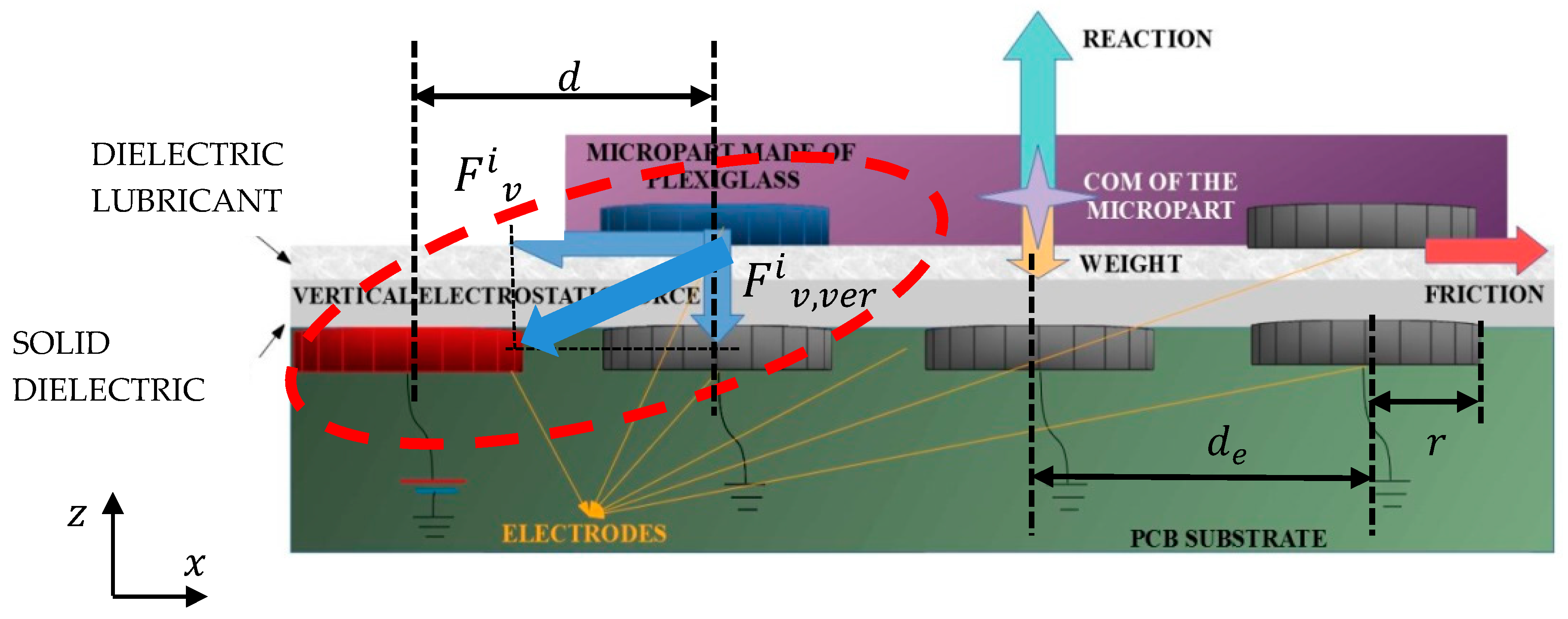
The “smart platform” (SP) is a Printed Circuit Board (PCB) with circular grounded conductive electrodes and two dielectric layers on top that are positioned according to the cross-section shown in
Figure 1 [
23]. On the top of this microelectromechanical system (MEMS), the insulating glass-type material microparts with circular conductive underneath, can be manipulated due to the electrostatic forces that are presented between the adjacent charged SP and micropart electrodes. The position of the microparts are detected with the aid of the vision system. Then, as it is shown in
Figure 1, the SP electrodes get charged, when a constant positive potential is applied to them. As a result, the micropart’s electrodes that are positioned close to the charged area, get charged negatively due to the polarization of the dielectric layers. Finally, the micropart electrode is attracted by the corresponding charged SP electrode, and in the case that the electrostatic forces between them are strong enough, the micropart leaves its current equilibrium position and moves to reach a new one. The electrostatic force between a charged SP electrode and a corresponding micropart electrode were studied and semi-empirical models for the force function with respect to their centers planar distance (
is presented in [
25,
26,
27].
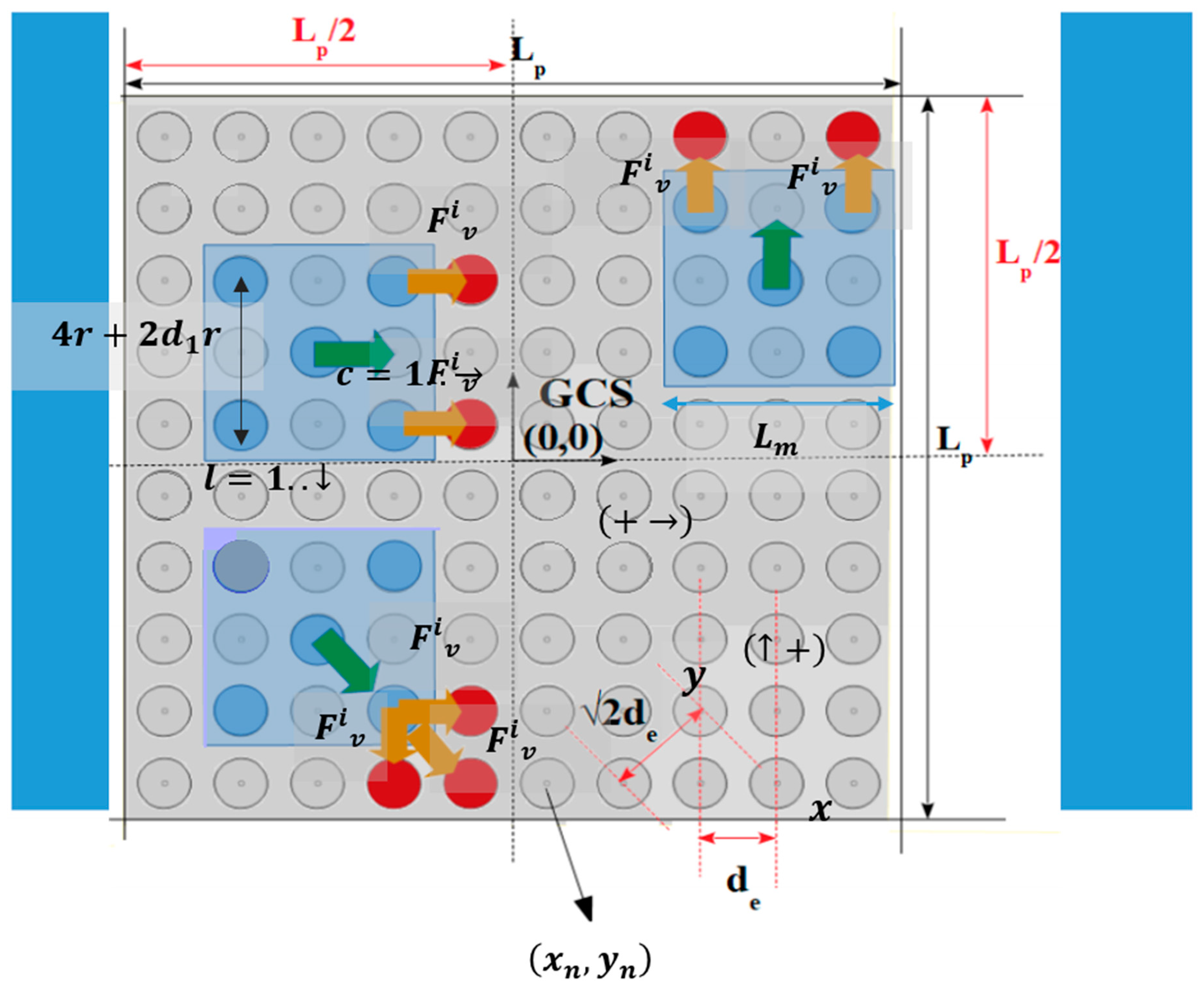
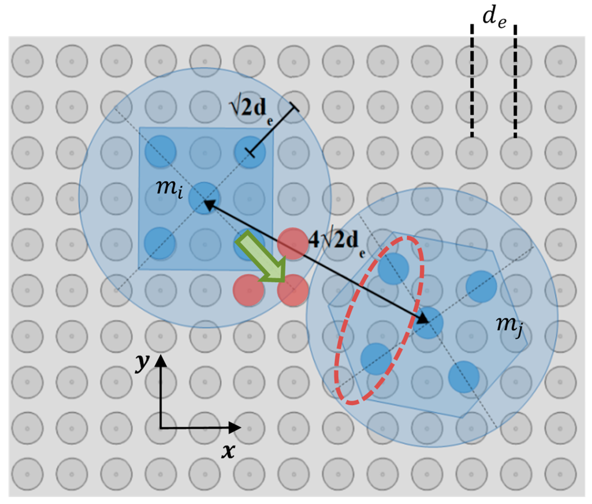
As is shown in
Figure 2, the SP has a square form with a side length equal to
where the Global Coordinate System (GCS) coincides with the SP’s center of symmetry. The conductive electrodes create a grid where,
the coordinates of the
SP electrode, which is defined according to the columns and lines counting method for a two dimensional array:
where
is the column and the
l line, respectively [
28]. The electrodes are placed on the SP following a layout so that their centers’ horizontal/vertical Euclidean distance [
29]
is equal to
where
is the radius of the electrodes. The
is a coefficient to adjust the distance between the centers of electrodes so that the amplitude of the electrostatic forces is enough for moving the microparts, while the undesirable arc phenomenon to be avoided [
30]. The value of distance
is determined so that
. The value of
is selected considering the dimensions of the micropart in order to limit the drag forces that are presented between the liquid dielectric layer and the micropart. The SP is used for the contactless micromanipulation exclusively with electrostatic forces without mechanical vibrations as in [
15,
16,
31]. Thus, the limitation of the magnitude of the adhesive forces, which are more intense when the size of the microparts gets increased [
32], is achieved when the length
is less than
. So, t the microparts and the SP electrode radius have to be ranged between: 1
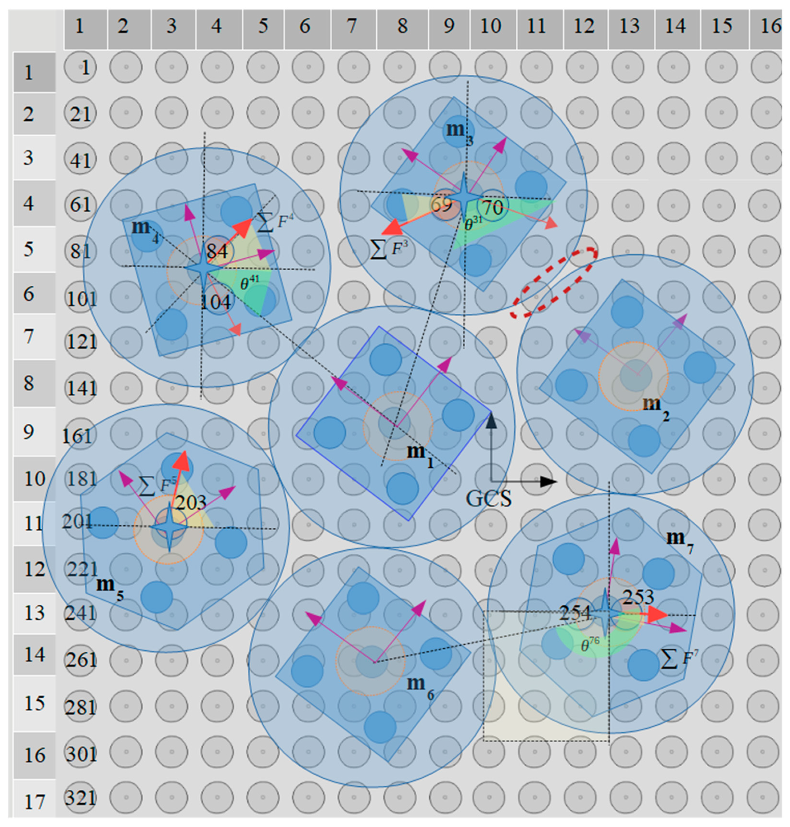
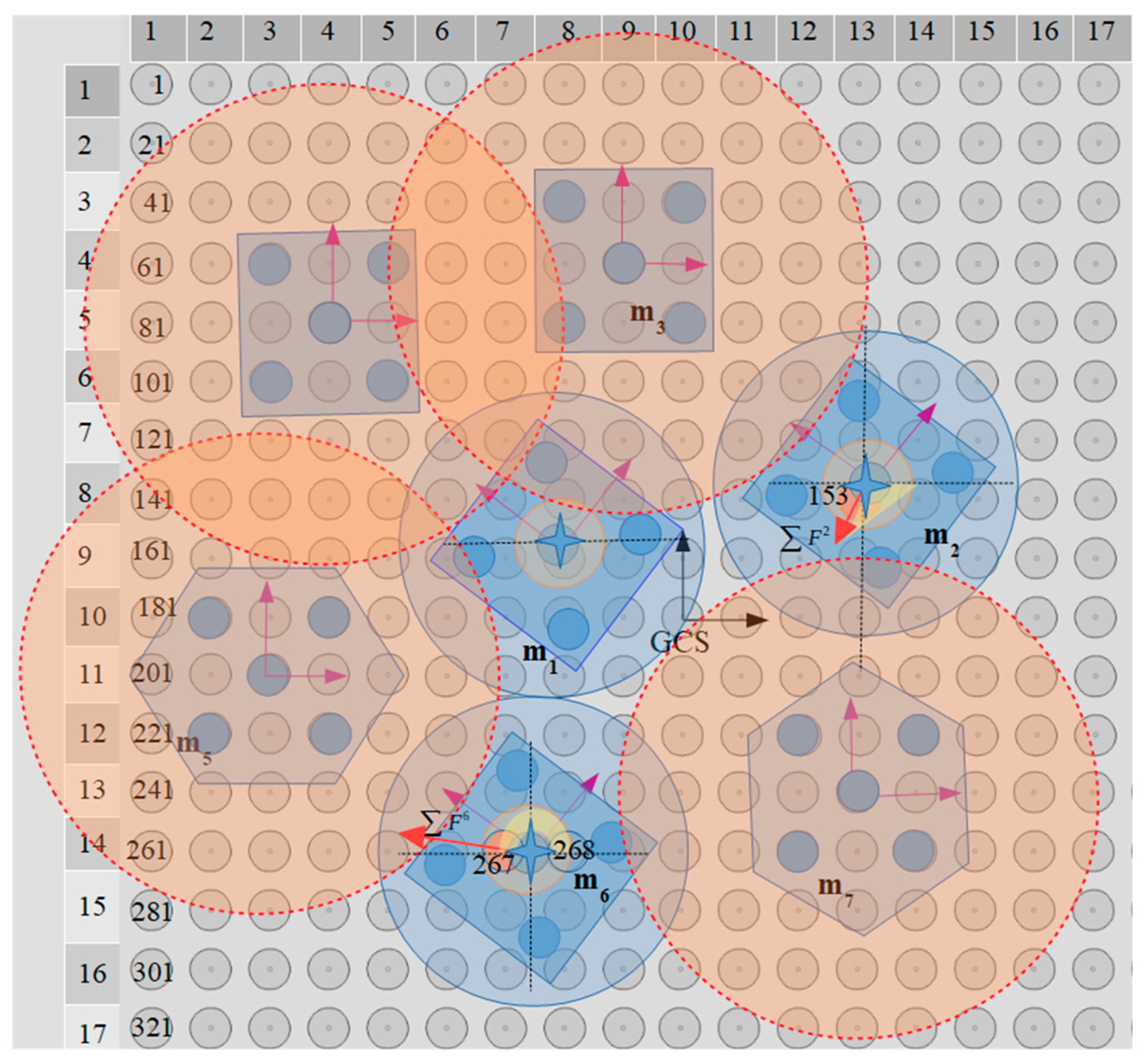
The five circular conductive electrodes are placed underneath the hexagonal and square plastic/plexiglass microparts formatting the square corners layout, which is proposed in [
26]. The planar forces that are presented between the micropart and the SP activated electrodes, resulting in its motion are the outgrowth of the successive activation of the micropart’s adjacent SP electrodes. In
Figure 2, the activation methods for the horizontal, vertical, and diagonal motion of the centralized and aligned static microparts between two equilibrium positions are illustrated [
25,
26].
The total attractive electrostatic force between the electrodes is the sum of the
and
vectors shown in
Figure 1, where the
represents the planar electrostatic force and the
the vertical, respectively. The
and
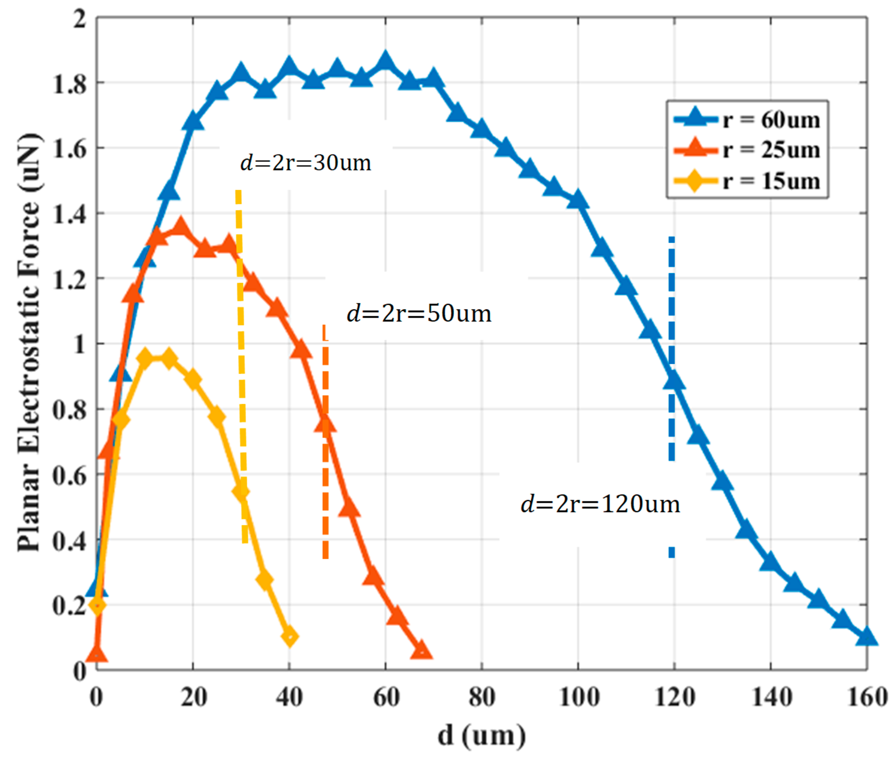
with respect to the charged SP electrode and micropart’s electrode centers horizontal distance (
(interaction in the red ellipse in
Figure 1), is studied using FEM analysis for three different radiuses of the electrodes. The radius of the SP and micropart electrodes is equal to
and
so that
and
and the voltage that is applied to each is equal to 50, 50, and 75 V, respectively [
25]. The solid dielectric
with
and the oil lubricant with dielectric properties due to the
nanoparticles oil additives [
33] with dielectric constant equal to
[
34] and static force coefficient
[
35] are used. In
Figure 3, the determinations of the planar electrostatic force between the charged SP electrode and the micropart electrode with respect to
are shown.
The micropart leaves its static condition when:
where
is the total number of the simultaneously activated SP electrodes,
the activated SP electrode that interacts with the
electrode of the
micropart
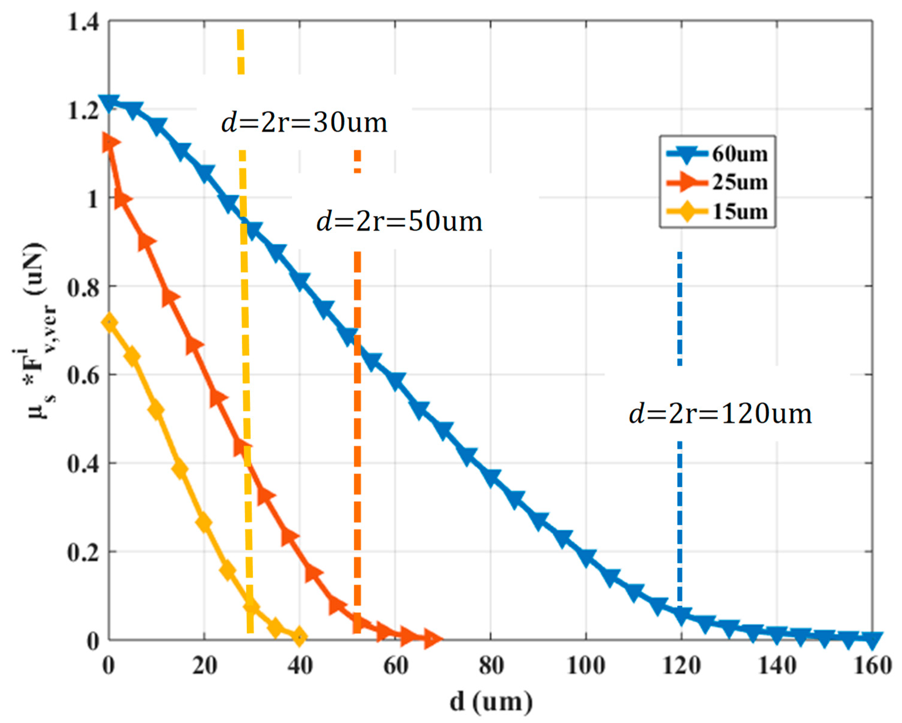
is the static friction force between the micropart and the dielectric lubricant that is equal to
where
is the weight of the micropart. Considering that the weight
of the micropart is a negligible value the contribution of the
is compared to
In
Figure 4, the vertical electrostatic force determinations multiplied by
with respect to
is shown.
Considering the graphs in
Figure 3 and
Figure 4, the mode of the planar electrostatic force with respect to the electrodes distance differs significantly from the corresponding function of
vs.
The overlapping between the microparts and SP electrodes starts when
where as it is shown in
Figure 3 and
Figure 4, the planar electrostatic force is significantly greater than the
for
Specifically, when the overlapping between the electrodes is bigger than
the
and
decreases and increases significantly, respectively. But, the intensity of the vertical electrostatic contributes in the increase of the adhesive forces that trap the micropart on the SP [
36]. However, the micropart and the activated SP electrodes are a couple of positively and negatively charged plates with two dielectrics which temp to be self-assembled and centralized since their overlapping is bigger than 0% [
37]. So, the micropart electrode can be centralized on an activated SP electrode when
In the case that the overlapping between the electrodes is bigger than 95%, the micropart electrode is considered as centralized on the activated SP electrode. However, the micropart can be displaced due to a single SP electrode activation leaving its static condition when
The
and the
are described by a 6th grade and 3rd grade polynomial fitting function, respectively, which are used for the computations in the following Sections.
A demanding issue is the activation methods that are applied to the SP electrodes for the motion of the microparts between two equilibrium positions when they are not centralized (the micropart electrode underneath the COM of the micropart does not coincide with a SP electrode) and non-aligned with the GCS (randomly positioned microparts). The position of the microparts on the SP is detected by the vision system and its orientation is described with the template matching method [
38]. In
Section 3, the static analysis of a randomly positioned micropart is described in order to be used in the activation methods computation which will be discussed in the following sections.
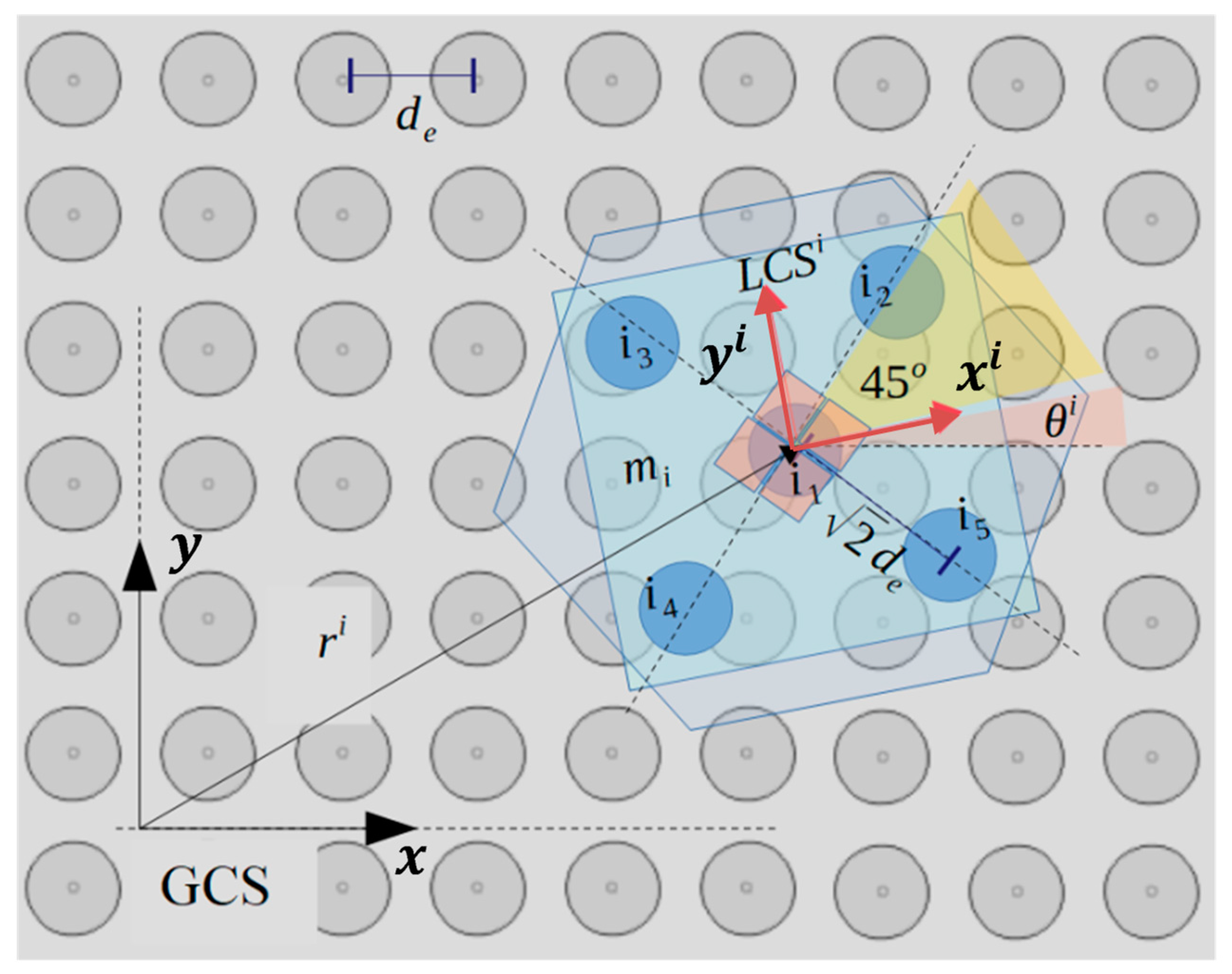
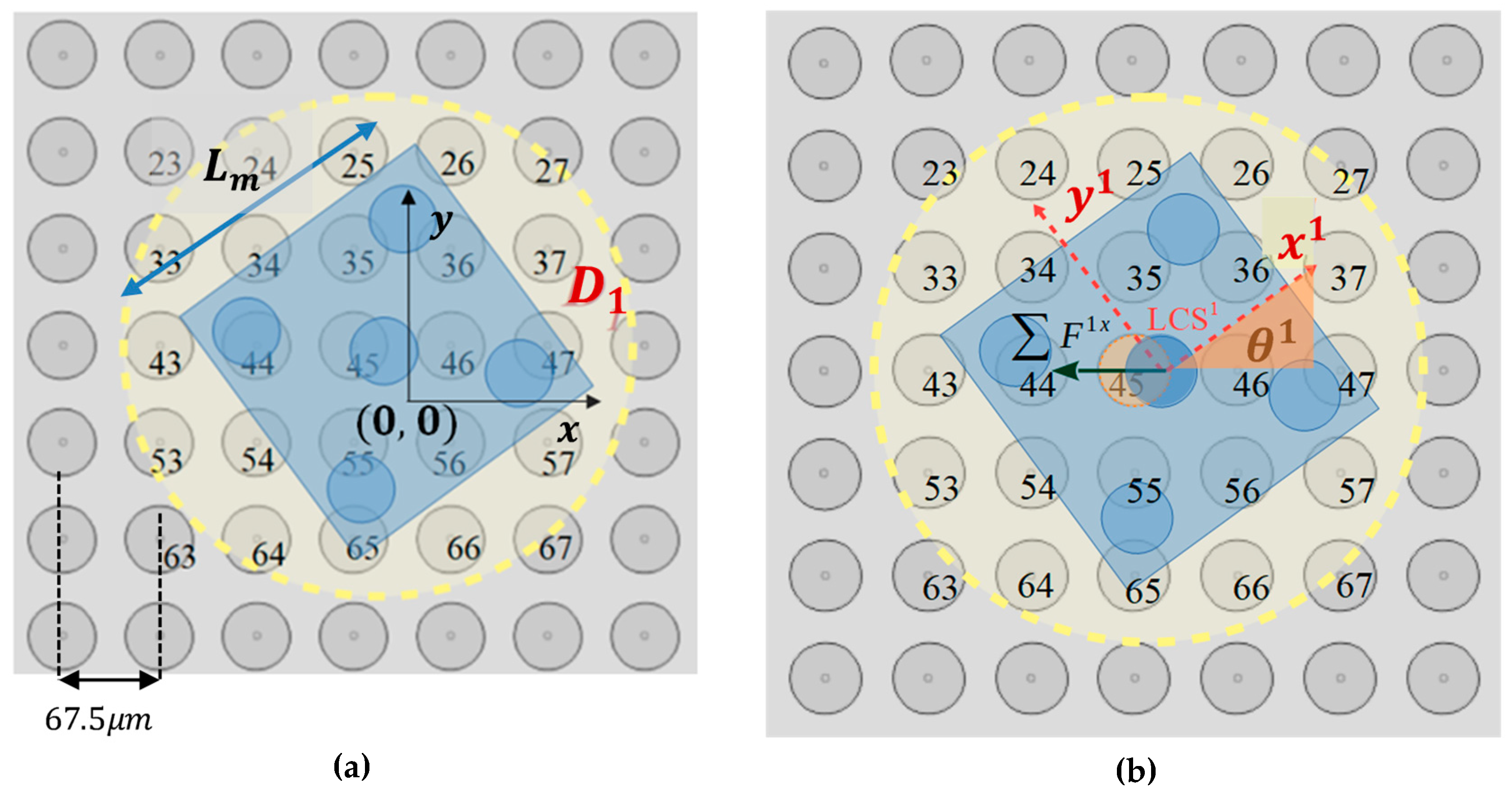
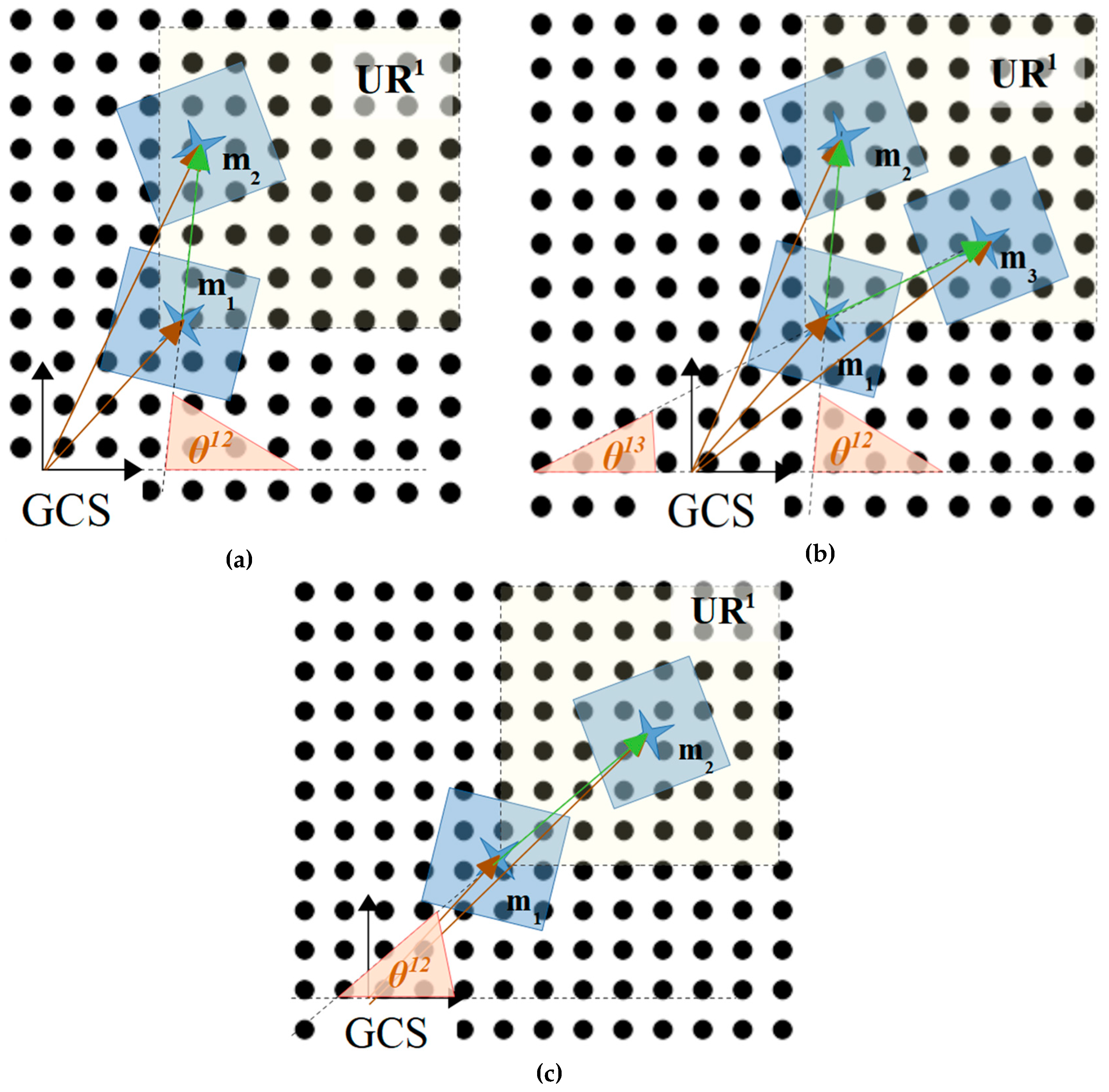
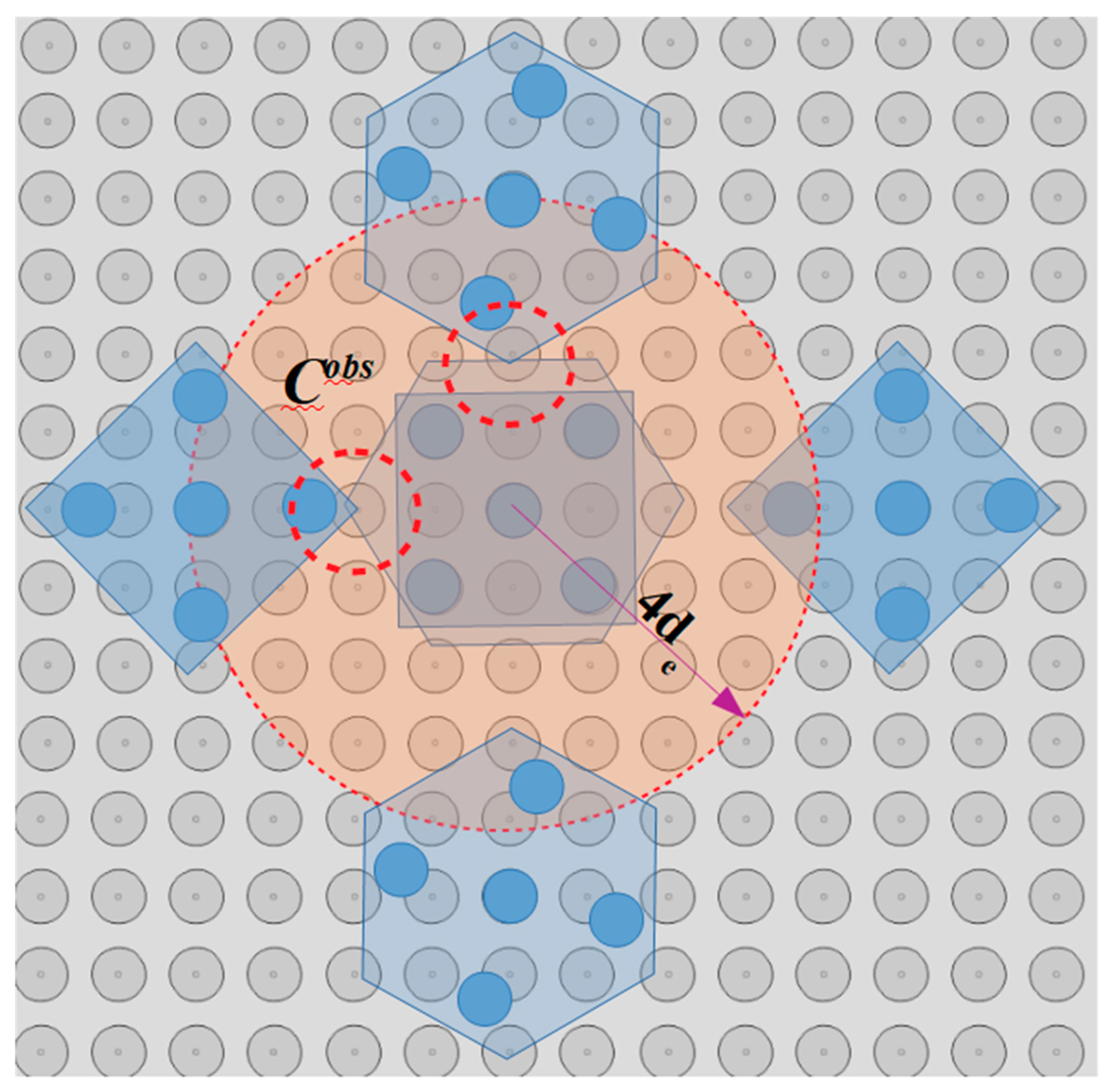
In
Figure 5, a part of the SP region and the square corners layout underneath the
randomly positioned micropart is illustrated. Each electrode’s configuration
is computed considering the vector
and the angle
that define the COM’s position and the micropart’s orientation with respect to the GCS, respectively. The micropart can reach any position on the SP apart from these at the edges of the SP, since it is driven out of the SP. Thus, the coordinates of the
have to satisfy the constraints:
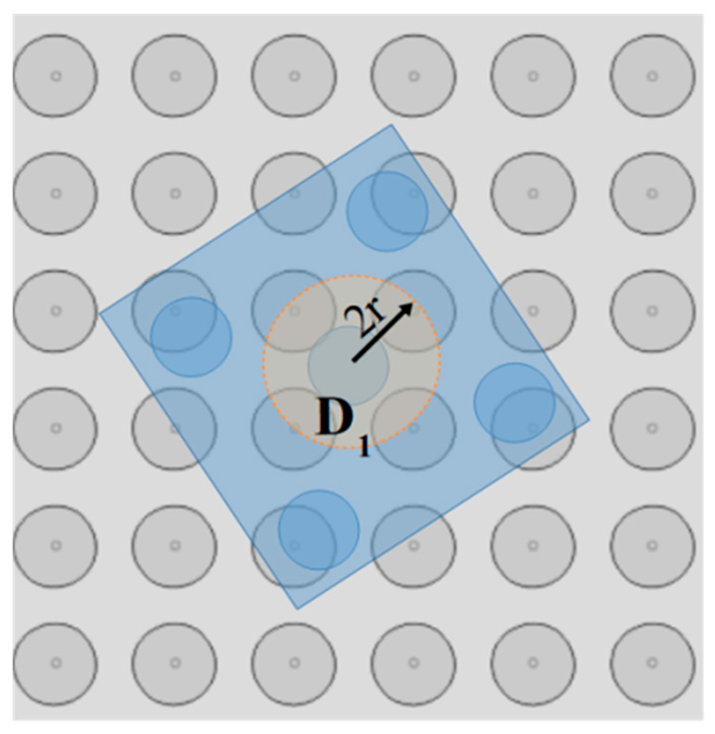
The five electrodes are positioned on the diagonals of their square corners layout so that when the COM of the micropart coincides with the center of a SP electrode and
all the micropart electrodes to coincide with a SP electrode, respectively. The position of the center of the
micropart electrodeis given by:
where the value of each
is included in
Table 2.
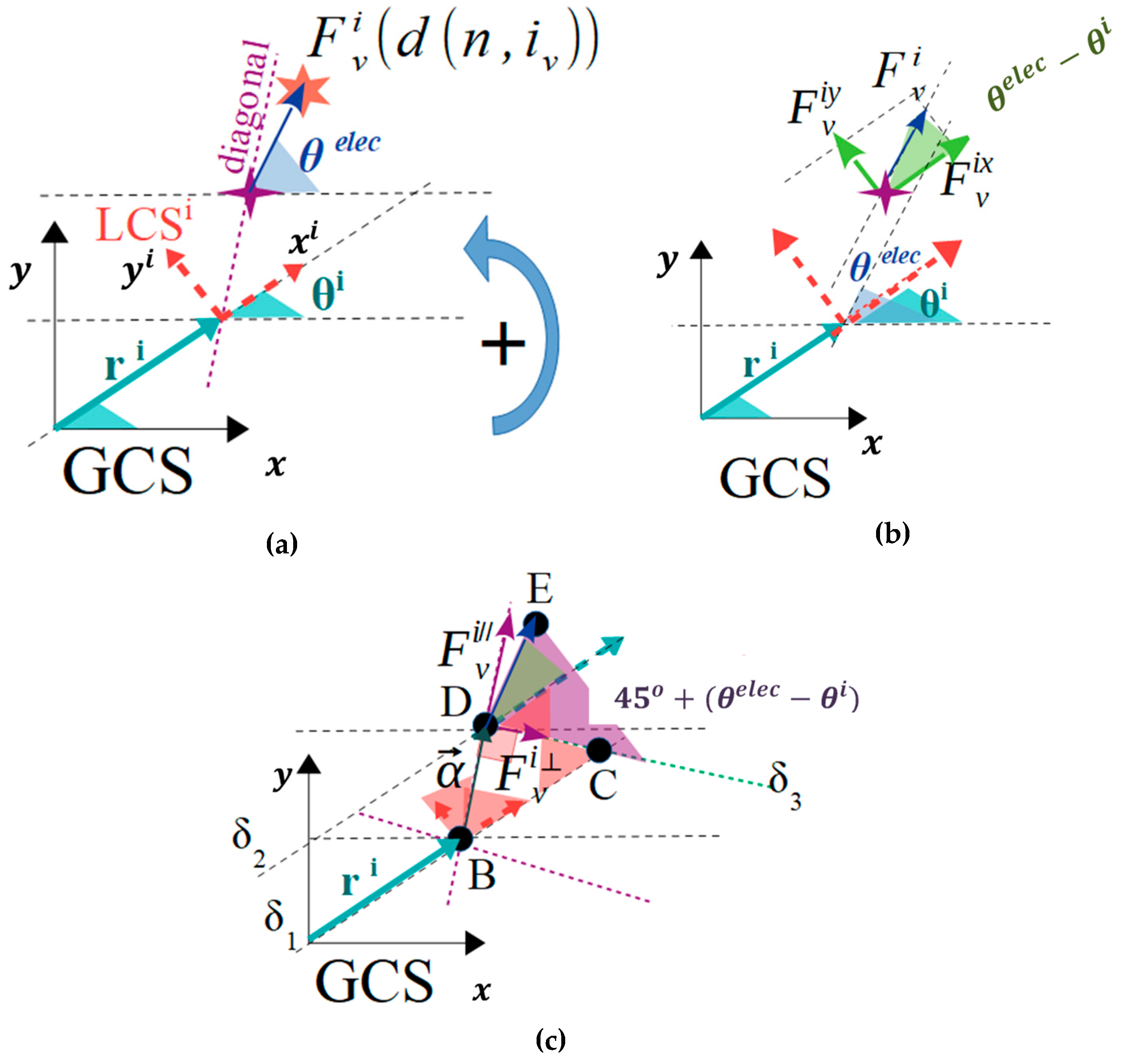
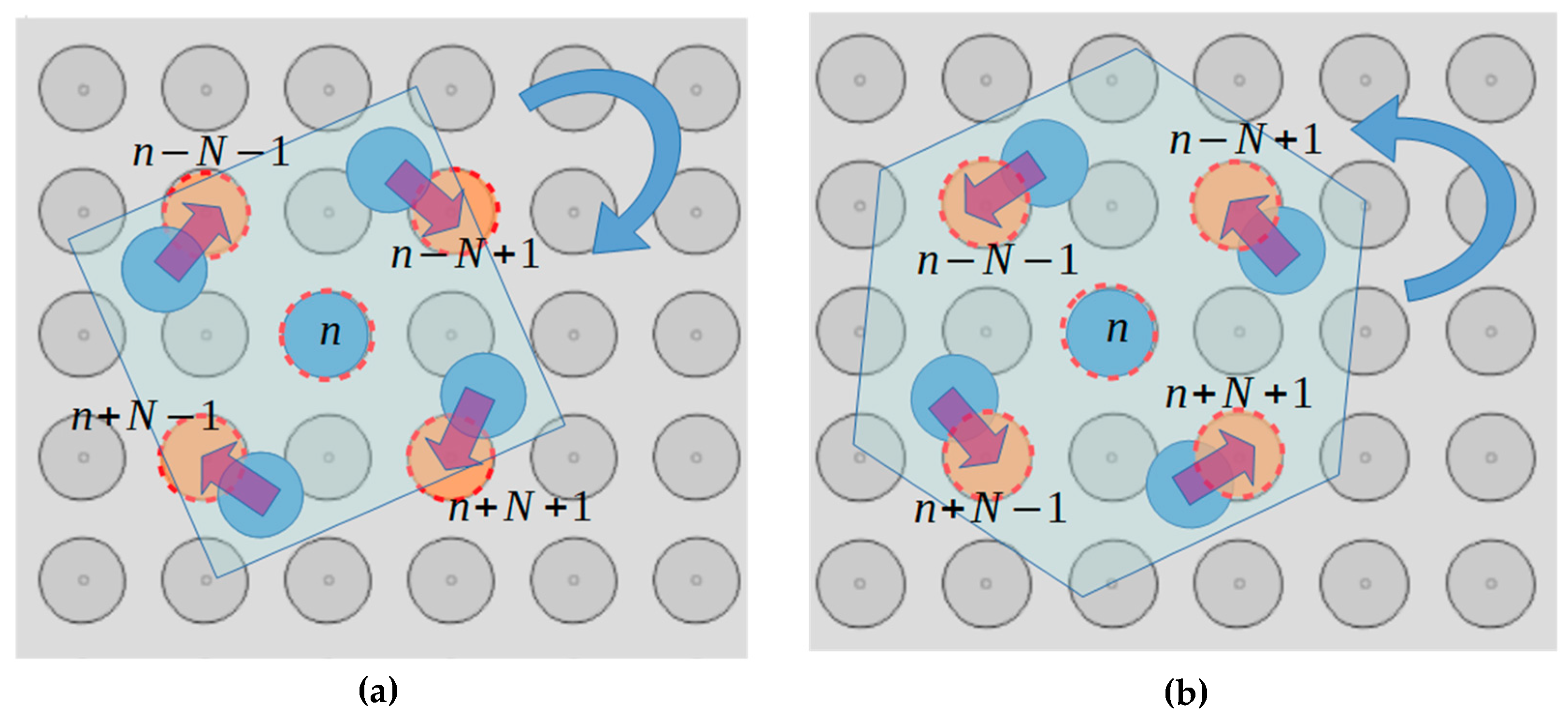
The planar forces and torques that are applied to a micropart with the square corners layout, due to the single interaction between an activated SP electrode and an adjacent micropart electrode, is studied in this section. A horizontal single interaction is shown in
Figure 6a, where the local coordinate system
of the micropart is represented with the red dashed vectors, the purple dashed line corresponds to one of the two diagonals of the square corners layout, and the purple star represents the center of the
micropart electrode. The pink star is the center of an activated SP electrode (
), which has sufficient distance from the micropart electrode so to interact with it, with an electrostatic force
(blue vector–symbol
in
Figure 6b,c. The statics analysis of the micropart and the contribution of the
in its translation is shown in
Figure 6b, where the
is analyzed to its components that are determined by:
As it is shown in
Figure 6c, the
vector is analyzed in two components where the
is parallel and the
is perpendicular to the diagonal. The
contributes in the rotation of the micropart and the torque is computed by:
where
a vector with magnitude equal to the distance between the COM of the micropart and the center of the micropart electrode parallel to the diagonal of the micropart. The value
for the analysis of the
component is computed considering the straight lines
and
which are parallel to the
vector crossing the
and the diagonal. The straight line
is parallel to the
and its cross-section with
and
results in the DCB triangle. The diagonal is also the bisectrix of the
thus
and since the DCB is an orthogonal triangle
the angle
is equal to
(the sum of the angles of a triangle theorem). The angles
and
are equal as the inside alternate angles, thus
and as it is shown in
Figure 6c, the remaining is the
angle between
and


