On-Chip Construction of Multilayered Hydrogel Microtubes for Engineered Vascular-Like Microstructures

 ,
, 
 and
and 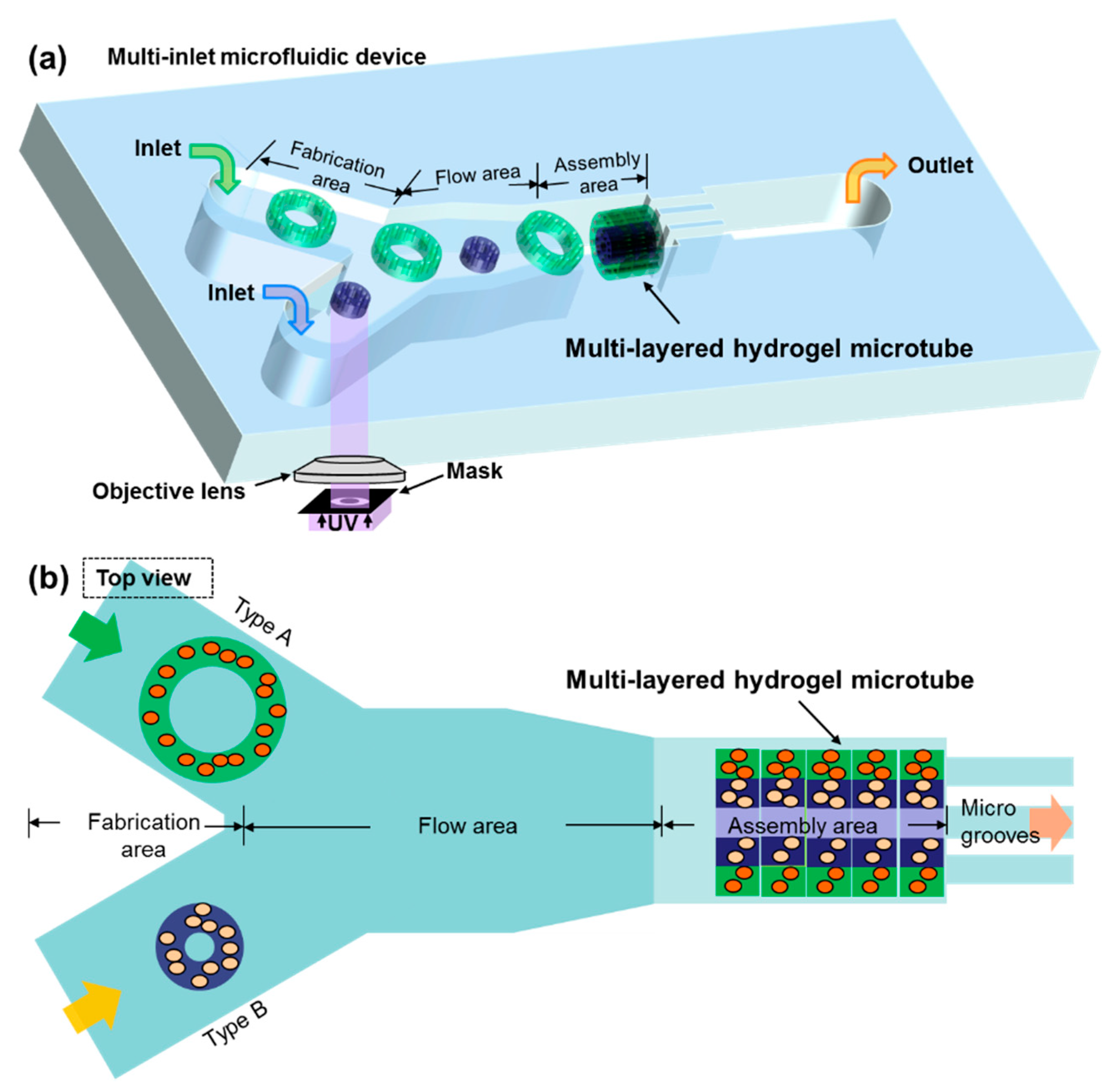
Abstract
1. Introduction
2. Materials and Methods
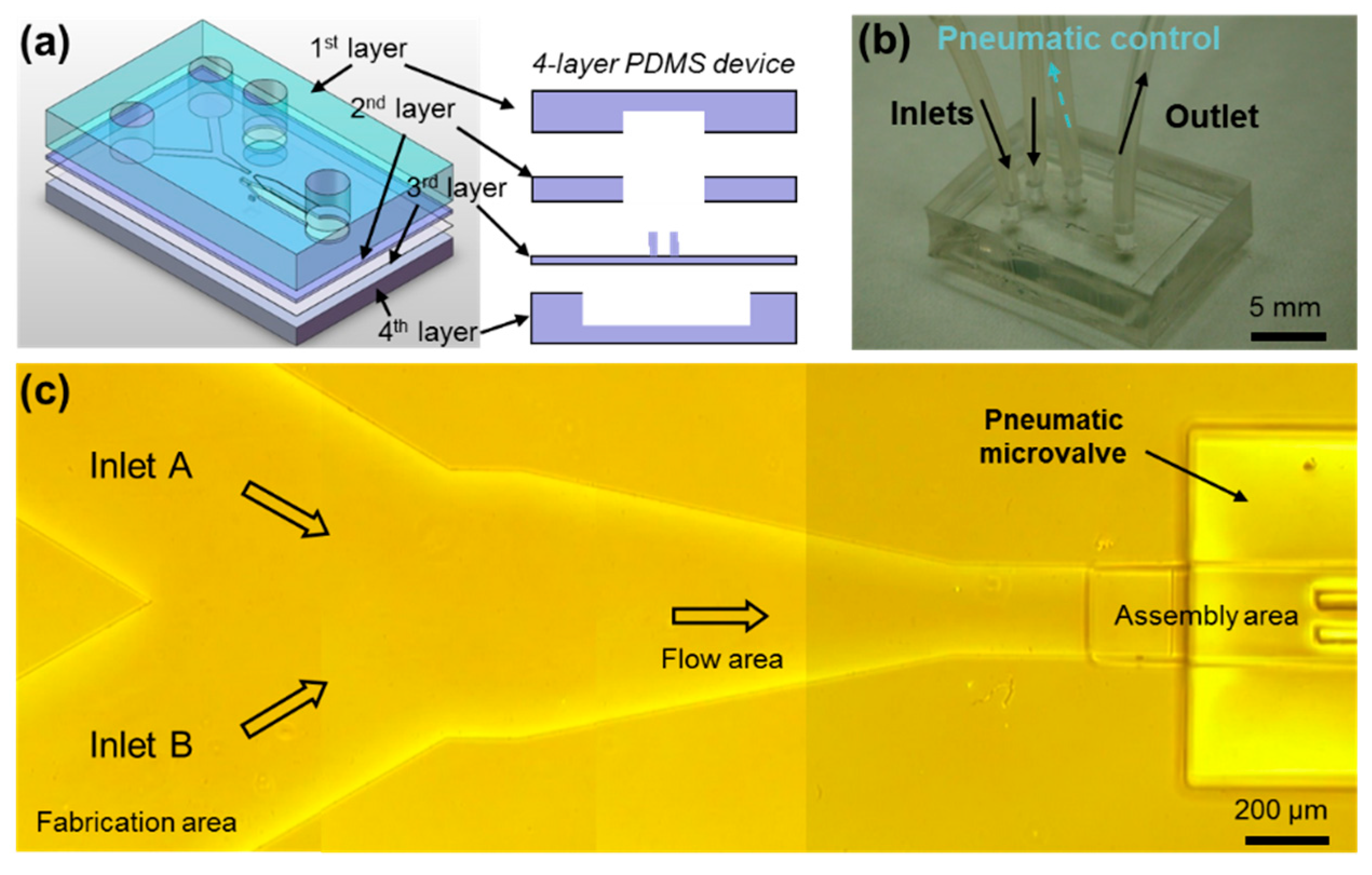
2.1. A Four-Layer Microfluidic Device With Two Inlets for Introducing Multiple Solutions
2.2. Prepolymer Solution of Photo-Crosslinkable Hydrogels
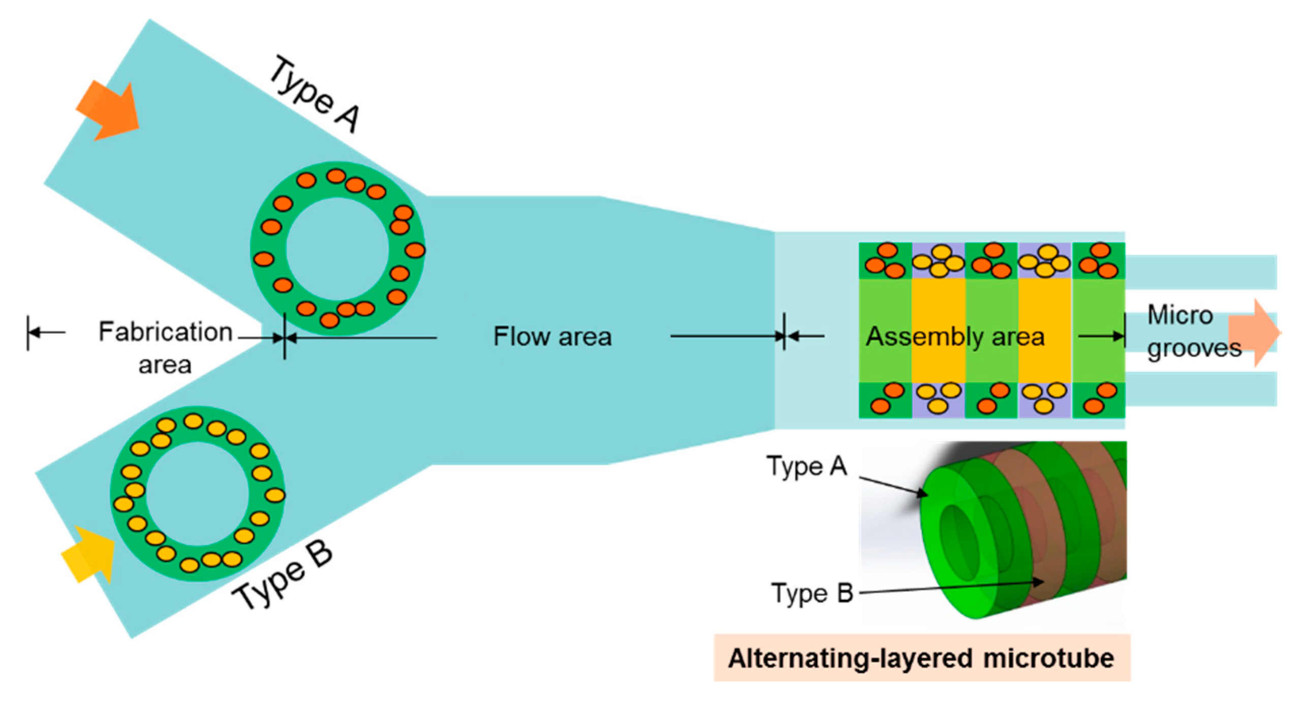
2.3. Assembly of Alternating-Layered Microtubes
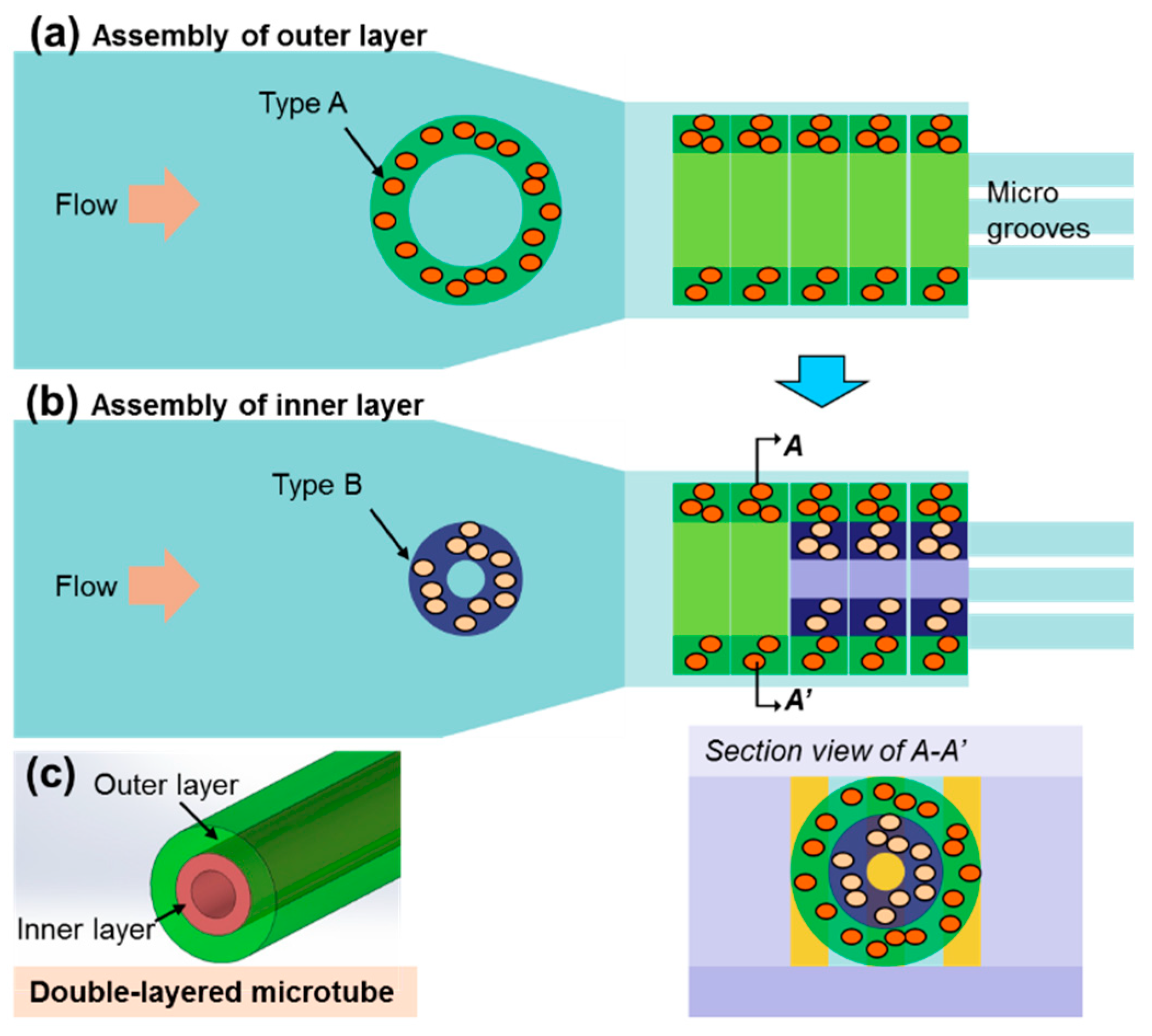
2.4. Assembly of Double-Layered Microtubes
2.5. Viability Evaluation of Cells Encapsulated Inside Microstructures
2.6. Data Acquisition and Analysis
3. Results and Discussion
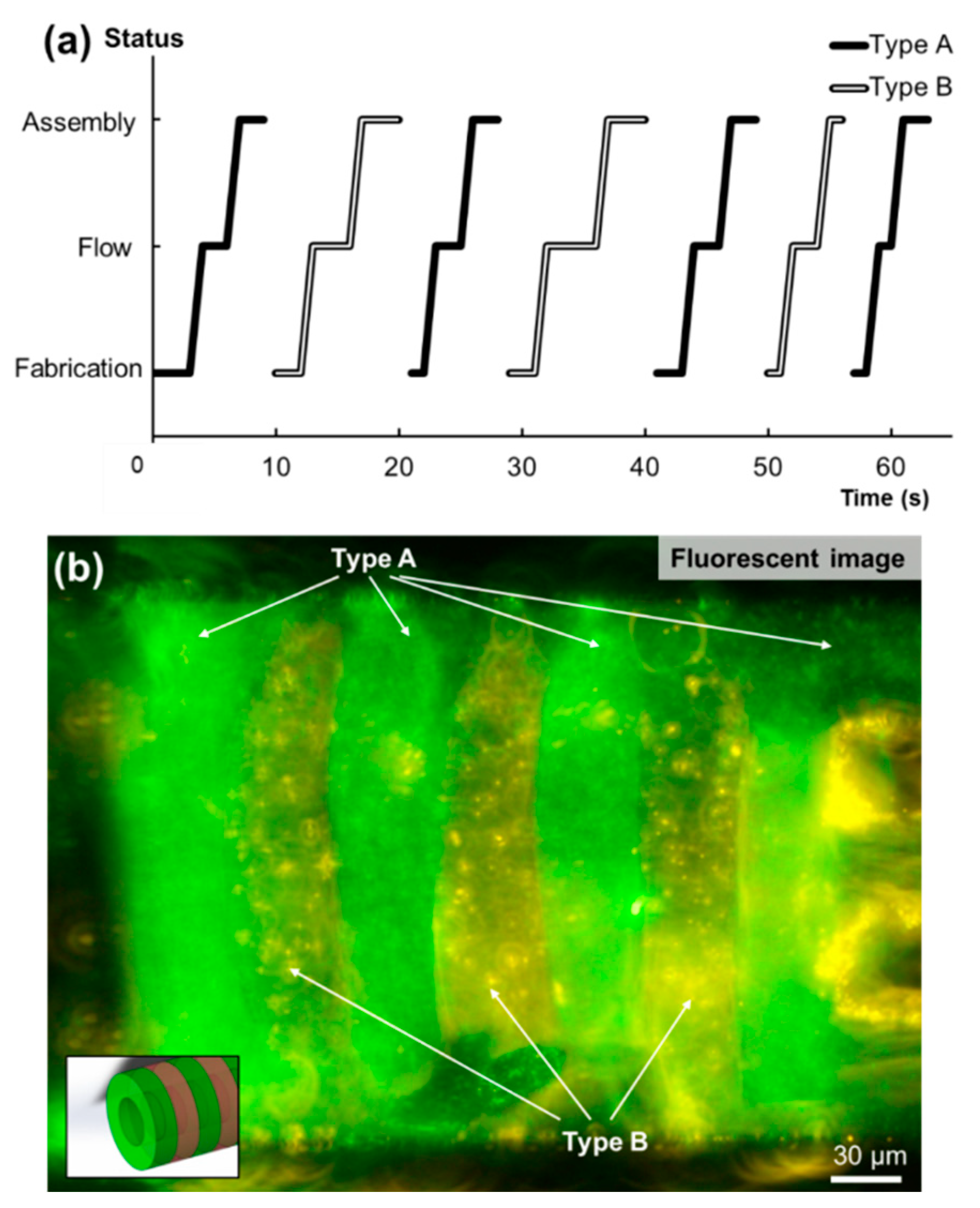
3.1. Alternating-Layered Microtubes are Assembled by Controlling the Fabrication, Flow, and Assembling Sequences On-Chip
3.2. Optimized Diameter of Inner Layer Structures was Obtained for Assembling Double-Layered Microtubes
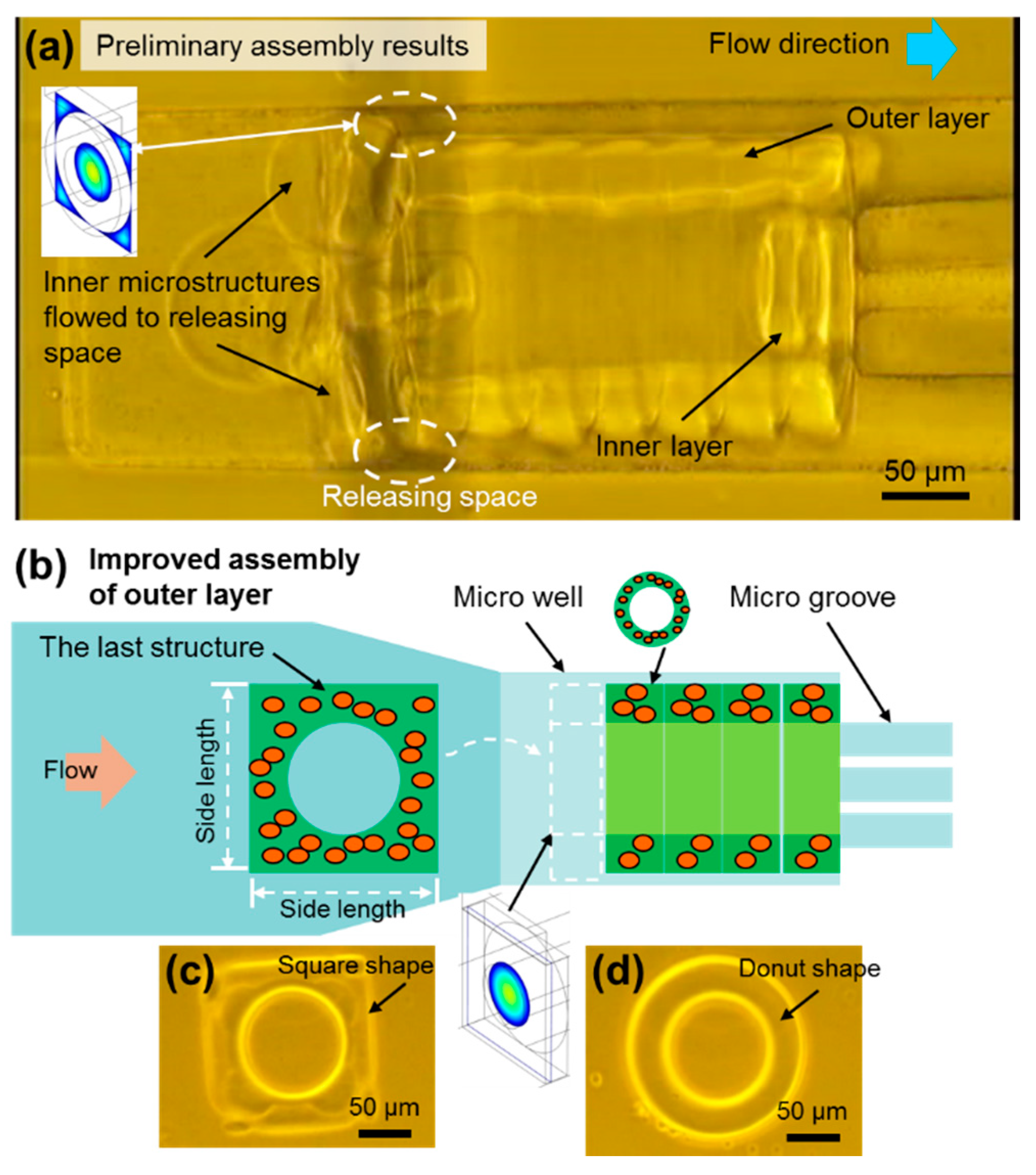
3.3. Square-Shaped Outer Layer Microstructures were UtiLized to Modify the Flow Conditions for Improving the Assembly of Double-Layered Microtubes
3.4. High-Efficient Assembly of Double-Layered Microtubes as Engineered Vascular-Like Microstructures
4. Conclusions
Supplementary Materials
Author Contributions
Funding
Conflicts of Interest
References
- Suuronen, E.J.; Sheardown, H.; Newman, K.D.; McLaughlin, C.R.; Griffith, M. Building In Vitro Models of Organs. In International Review of Cytology; Kwang, W.J., Ed.; Academic Press: Cambridge, MA, USA, 2005; Volume 244, pp. 137–173. [Google Scholar]
- Chen, S.; Nakamoto, T.; Kawazoe, N.; Chen, G. Engineering multi-layered skeletal muscle tissue by using 3D microgrooved collagen scaffolds. Biomaterials 2015, 73, 23–31. [Google Scholar] [CrossRef] [PubMed]
- Harrison, R.H.; St-Pierre, J.-P.; Stevens, M.M. Tissue Engineering and Regenerative Medicine: A Year in Review. Tissue Eng. Part B Rev. 2014, 20, 1–16. [Google Scholar] [CrossRef] [PubMed]
- Onoe, H.; Takeuchi, S. Cell-laden microfibers for bottom-up tissue engineering. Drug Discov. Today 2015, 20, 236–246. [Google Scholar] [CrossRef] [PubMed]
- Gao, Q.; He, Y.; Fu, J.-Z.; Liu, A.; Ma, L. Coaxial nozzle-assisted 3D bioprinting with built-in microchannels for nutrients delivery. Biomaterials 2015, 61, 203–215. [Google Scholar] [CrossRef]
- Hasan, A.; Paul, A.; Memic, A.; Khademhosseini, A. A multilayered microfluidic blood vessel-like structure. Biomed. Microdevices 2015, 17, 88. [Google Scholar] [CrossRef]
- Chung, B.G.; Kang, L.F.; Khademhosseini, A. Micro- and nanoscale technologies for tissue engineering and drug discovery applications. Expert Opin. Drug Discov. 2007, 2, 1653–1668. [Google Scholar] [CrossRef]
- Liu, Y.; Zhang, Y.; Jiang, W.; Peng, Y.; Luo, J.; Xie, S.; Zhong, S.; Pu, H.; Liu, N.; Yue, T. A Novel Biodegradable Multilayered Bioengineered Vascular Construct with a Curved Structure and Multi-Branches. Micromachines 2019, 10, 275. [Google Scholar] [CrossRef]
- Nichol, J.W.; Khademhosseini, A. Modular tissue engineering: Engineering biological tissues from the bottom up. Soft Matter 2009, 5, 1312–1319. [Google Scholar] [CrossRef]
- Du, Y.; Ghodousi, M.; Qi, H.; Haas, N.; Xiao, W.; Khademhosseini, A. Sequential assembly of cell-laden hydrogel constructs to engineer vascular-like microchannels. Biotechnol. Bioeng. 2011, 108, 1693–1703. [Google Scholar] [CrossRef]
- Tsutsui, H.; Yu, E.; Marquina, S.; Valamehr, B.; Wong, I.; Wu, H.; Ho, C.M. Efficient Dielectrophoretic Patterning of Embryonic Stem Cells in Energy Landscapes Defined by Hydrogel Geometries. Ann. Biomed. Eng. 2010, 38, 3777–3788. [Google Scholar] [CrossRef]
- Tixier-Mita, A.; Jun, J.; Ostrovidov, S.; Chiral, M.; Frenea, M.; Le Pioufle, B.; Fujita, H. A Silicon Micro-System for Parallel Gene Transfection into Arrayed Cells. In Proceedings of the 8th International Conference on Miniaturized Systems for Chemistry and Life Sciences, Malmo, Sweden, 26–30 September 2004; pp. 180–182. [Google Scholar]
- Cui, H.H.; Lim, K.M. Pillar Array Microtraps with Negative Dielectrophoresis. Langmuir 2009, 25, 3336–3339. [Google Scholar] [CrossRef] [PubMed][Green Version]
- Hu, S.; Chen, S.; Xu, G.; Sun, D. Automated Transportation of Multiple Cell Types Using a Robot-Aided Cell Manipulation System with Holographic Optical Tweezers. IEEE/ASME Trans. Mechatron. 2016, 22, 804–814. [Google Scholar] [CrossRef]
- Hagiwara, M.; Kawahara, T.; Yamanishi, Y.; Masuda, T.; Feng, L.; Arai, F. On-chip magnetically actuated robot with ultrasonic vibration for single cell manipulations. Lab Chip 2011, 11, 2049–2054. [Google Scholar] [CrossRef] [PubMed]
- Di Carlo, D.; Aghdam, N.; Lee, L.P. Single-cell enzyme concentrations, kinetics, and inhibition analysis using high-density hydrodynamic cell isolation arrays. Anal. Chem. 2006, 78, 4925–4930. [Google Scholar] [CrossRef] [PubMed]
- Yue, K.; Trujillo-de Santiago, G.; Alvarez, M.M.; Tamayol, A.; Annabi, N.; Khademhosseini, A. Synthesis, properties, and biomedical applications of gelatin methacryloyl (GelMA) hydrogels. Biomaterials 2015, 73, 254–271. [Google Scholar] [CrossRef] [PubMed]
- Yue, T.; Nakajima, M.; Takeuchi, M.; Fukuda, T. Improved Laser Manipulation for On-chip Fabricated Microstructures Based on Solution Replacement and Its Application in Single Cell Analysis. Int. J. Adv. Robot. Syst. 2014, 11, 11. [Google Scholar] [CrossRef]
- Yue, T.; Nakajima, M.; Tajima, H.; Fukuda, T. Fabrication of Microstructures Embedding Controllable Particles Inside Dielectrophoretic Microfluidic Devices. Int. J. Adv. Robot. Syst. 2013, 10, 132. [Google Scholar] [CrossRef]
- Du, Y.; Lo, E.; Ali, S.; Khademhosseini, A. Directed assembly of cell-laden microgels for fabrication of 3D tissue constructs. Proc. Natl. Acad. Sci. USA 2008, 105, 9522–9527. [Google Scholar] [CrossRef]
- Jakab, K.; Norotte, C.; Marga, F.; Murphy, K.; Vunjak-Novakovic, G.; Forgacs, G. Tissue engineering by self-assembly and bio-printing of living cells. Biofabrication 2010, 2, 022001. [Google Scholar] [CrossRef]
- Kolesky, D.B.; Homan, K.A.; Skylar-Scott, M.A.; Lewis, J.A. Three-dimensional bioprinting of thick vascularized tissues. Proc. Natl. Acad. Sci. USA 2016, 113, 3179. [Google Scholar] [CrossRef]
- Homan, K.A.; Kolesky, D.B.; Skylar-Scott, M.A.; Herrmann, J.; Obuobi, H.; Moisan, A.; Lewis, J.A. Bioprinting of 3D Convoluted Renal Proximal Tubules on Perfusable Chips. Sci. Rep. 2016, 6, 34845. [Google Scholar] [CrossRef] [PubMed]
- Skylar-Scott, M.A.; Uzel, S.G.M.; Nam, L.L.; Ahrens, J.H.; Truby, R.L.; Damaraju, S.; Lewis, J.A. Biomanufacturing of organ-specific tissues with high cellular density and embedded vascular channels. Sci. Adv. 2019, 5, eaaw2459. [Google Scholar] [CrossRef] [PubMed]
- Noor, N.; Shapira, A.; Edri, R.; Gal, I.; Wertheim, L.; Dvir, T. 3D Printing of Personalized Thick and Perfusable Cardiac Patches and Hearts. Adv. Sci. 2019, 6, 1900344. [Google Scholar] [CrossRef] [PubMed]
- Bischel, L.L.; Young, E.W.K.; Mader, B.R.; Beebe, D.J. Tubeless microfluidic angiogenesis assay with three-dimensional endothelial-lined microvessels. Biomaterials 2013, 34, 1471–1477. [Google Scholar] [CrossRef]
- Xi, W.; Sonam, S.; Beng Saw, T.; Ladoux, B.; Teck Lim, C. Emergent patterns of collective cell migration under tubular confinement. Nat. Commun. 2017, 8, 1517. [Google Scholar] [CrossRef]
- Whitesides, G.M.; Grzybowski, B. Self-assembly at all scales. Science 2002, 295, 2418–2421. [Google Scholar] [CrossRef]
- Zheng, W.; Jacobs, H.O. Fabrication of multicomponent microsystems by directed three-dimensional self-assembly. Adv. Funct. Mater. 2005, 15, 732–738. [Google Scholar] [CrossRef]
- Kato-Negishi, M.; Morimoto, Y.; Onoe, H.; Takeuchi, S. Millimeter-Sized Neural Building Blocks for 3D Heterogeneous Neural Network Assembly. Adv. Healthc. Mater. 2013, 2, 1564–1570. [Google Scholar] [CrossRef]
- Jakab, K.; Neagu, A.; Mironov, V.; Markwald, R.R.; Forgacs, G. Engineering biological structures of prescribed shape using self-assembling multicellular systems. Proc. Natl. Acad. Sci. USA 2004, 101, 2864–2869. [Google Scholar] [CrossRef]
- Liu, N.; Du, P.; Xiao, X.; Liu, Y.; Peng, Y.; Yang, C.; Yue, T. Microfluidic-Based Mechanical Phenotyping of Androgen-Sensitive and Non-sensitive Prostate Cancer Cells Lines. Micromachines 2019, 10, 602. [Google Scholar] [CrossRef]
- Kuribayashi-Shigetomi, K.; Onoe, H.; Takeuchi, S. Cell Origami: Self-Folding of Three-Dimensional Cell-Laden Microstructures Driven by Cell Traction Force. PLoS ONE 2012, 7, e51085. [Google Scholar] [CrossRef] [PubMed]
- Gauvin, R.; Ahsan, T.; Larouche, D.; Levesque, P.; Dube, J.; Auger, F.A.; Nerem, R.M.; Germain, L. A Novel Single-Step Self-Assembly Approach for the Fabrication of Tissue-Engineered Vascular Constructs. Tissue Eng. Part A 2010, 16, 1737–1747. [Google Scholar] [CrossRef] [PubMed]
- Khoo, H.S.; Lin, C.; Huang, S.-H.; Tseng, F.-G. Self-Assembly in Micro- and Nanofluidic Devices: A Review of Recent Efforts. Micromachines 2011, 2, 17–48. [Google Scholar] [CrossRef]
- Gruene, M.; Pflaum, M.; Hess, C.; Diamantouros, S.; Schlie, S.; Deiwick, A.; Koch, L.; Wilhelmi, M.; Jockenhoevel, S.; Haverich, A.; et al. Laser Printing of Three-Dimensional Multicellular Arrays for Studies of Cell-Cell and Cell-Environment Interactions. Tissue Eng. Part C Methods 2011, 17, 973–982. [Google Scholar] [CrossRef]
- Quante, M.; Wang, T.C. Stem cells in gastroenterology and hepatology. Nat. Rev. Gastroenterol. Hepatol. 2009, 6, 724–737. [Google Scholar] [CrossRef]
- Matsusaki, M.; Case, C.P.; Akashi, M. Three-dimensional cell culture technique and pathophysiology. Adv. Drug Deliv. Rev. 2014, 74, 95–103. [Google Scholar] [CrossRef]
- Liu, Y.; Wu, C.; Lai, H.S.S.; Liu, Y.T.; Li, W.J.; Shen, Y.J. Three-Dimensional Calcium Alginate Hydrogel Assembly via TiOPc-Based Light-Induced Controllable Electrodeposition. Micromachines 2017, 8, 192. [Google Scholar] [CrossRef]
- Emmert, M.Y.; Hitchcock, R.W.; Hoerstrup, S.P. Cell therapy, 3D culture systems and tissue engineering for cardiac regeneration. Adv. Drug Deliv. Rev. 2014, 69–70, 254–269. [Google Scholar] [CrossRef]
- Krawiec, J.T.; Vorp, D.A. Adult stem cell-based tissue engineered blood vessels: A review. Biomaterials 2012, 33, 3388–3400. [Google Scholar] [CrossRef]
- L Berg, E.; Hsu, Y.-C.; Lee, J.A. Consideration of the cellular microenvironment: Physiologically relevant co-culture systems in drug discovery. Adv. Drug Deliv. Rev. 2014, 69–70, 190–204. [Google Scholar] [CrossRef]
- Yue, T.; Nakajima, M.; Takeuchi, M.; Hu, C.; Huang, Q.; Fukuda, T. On-chip self-assembly of cell embedded microstructures to vascular-like microtubes. Lab Chip 2014, 14, 1151–1161. [Google Scholar] [CrossRef] [PubMed]
- Roh, J.D.; Sawh-Martinez, R.; Brennan, M.P.; Jay, S.M.; Devine, L.; Rao, D.A.; Yi, T.; Mirensky, T.L.; Nalbandian, A.; Udelsman, B.; et al. Tissue-engineered vascular grafts transform into mature blood vessels via an inflammation-mediated process of vascular remodeling. Proc. Natl. Acad. Sci. USA 2010, 107, 4669–4674. [Google Scholar] [CrossRef] [PubMed]


© 2019 by the authors. Licensee MDPI, Basel, Switzerland. This article is an open access article distributed under the terms and conditions of the Creative Commons Attribution (CC BY) license (http://creativecommons.org/licenses/by/4.0/).
Share and Cite
Yue, T.; Liu, N.; Liu, Y.; Peng, Y.; Xie, S.; Luo, J.; Huang, Q.; Takeuchi, M.; Fukuda, T. On-Chip Construction of Multilayered Hydrogel Microtubes for Engineered Vascular-Like Microstructures. Micromachines 2019, 10, 840. https://doi.org/10.3390/mi10120840
Yue T, Liu N, Liu Y, Peng Y, Xie S, Luo J, Huang Q, Takeuchi M, Fukuda T. On-Chip Construction of Multilayered Hydrogel Microtubes for Engineered Vascular-Like Microstructures. Micromachines. 2019; 10(12):840. https://doi.org/10.3390/mi10120840
Chicago/Turabian StyleYue, Tao, Na Liu, Yuanyuan Liu, Yan Peng, Shaorong Xie, Jun Luo, Qiang Huang, Masaru Takeuchi, and Toshio Fukuda. 2019. "On-Chip Construction of Multilayered Hydrogel Microtubes for Engineered Vascular-Like Microstructures" Micromachines 10, no. 12: 840. https://doi.org/10.3390/mi10120840
APA StyleYue, T., Liu, N., Liu, Y., Peng, Y., Xie, S., Luo, J., Huang, Q., Takeuchi, M., & Fukuda, T. (2019). On-Chip Construction of Multilayered Hydrogel Microtubes for Engineered Vascular-Like Microstructures. Micromachines, 10(12), 840. https://doi.org/10.3390/mi10120840