A Novel Expanding Mechanism of Gastrointestinal Microrobot: Design, Analysis and Optimization

 ,
,
Abstract
1. Introduction
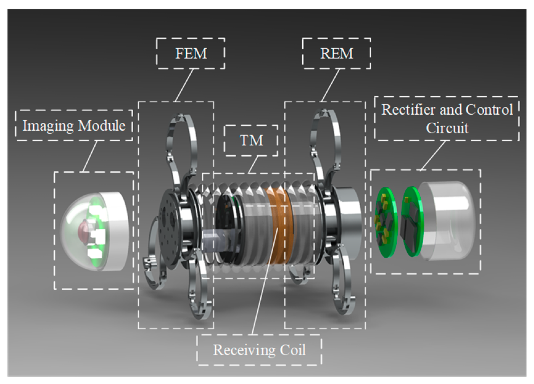
2. Robot System
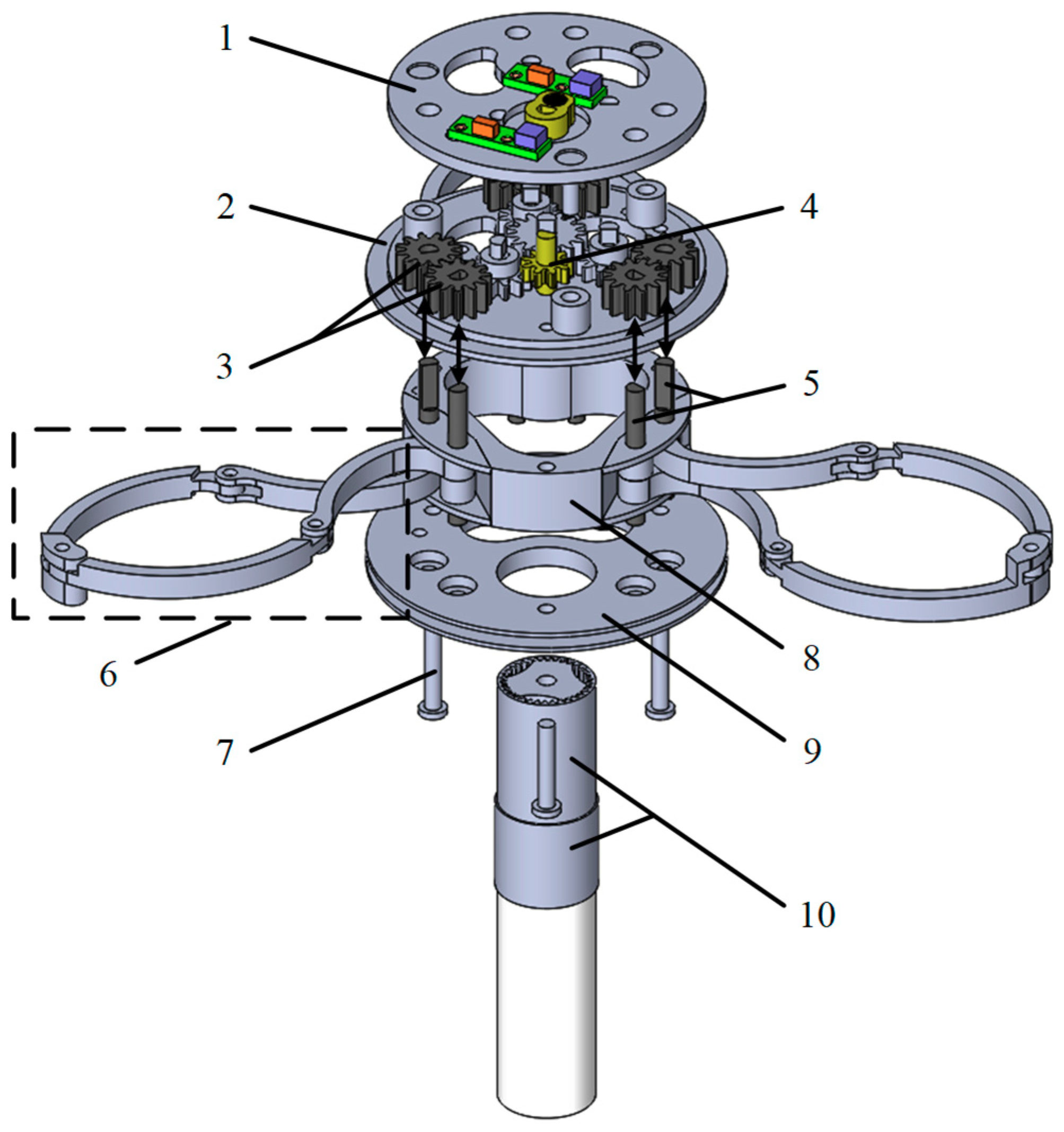
2.1. Structure of the Mechanism
2.2. Locomotion Principle
3. Kinematics and Mechanics Analysis of the Expanding Arm
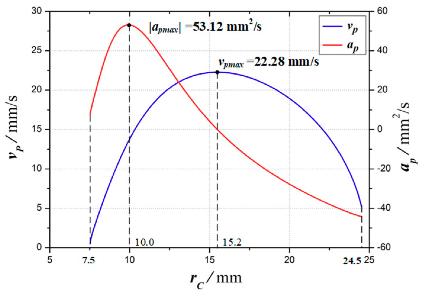
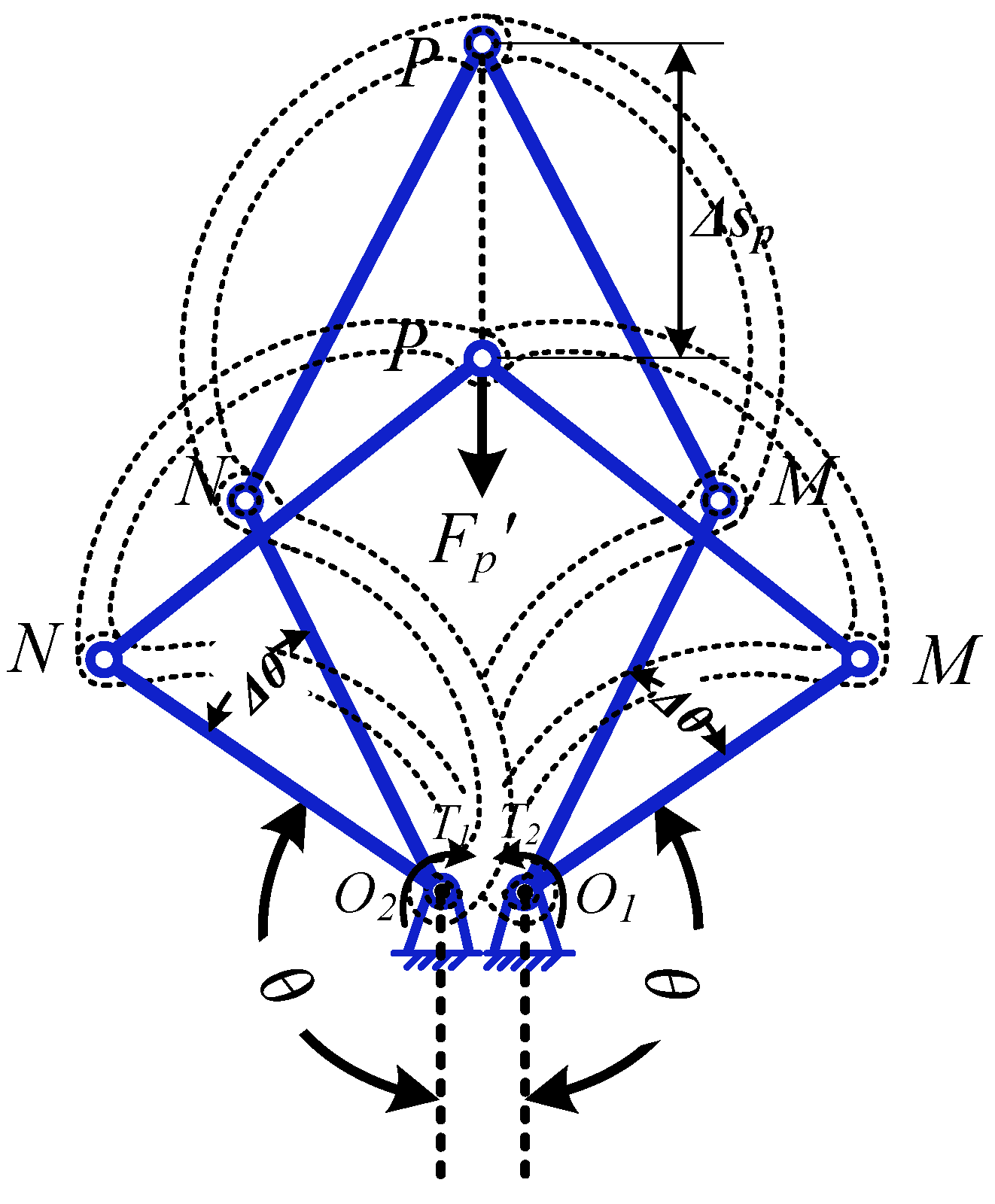
3.1. Kinematics Analysis
3.2. Expanding Force Analysis
4. Elastodynamic Analysis and Optimization
4.1. Elastodynamic Model
4.2. Elastodynamic Analysis by FEA
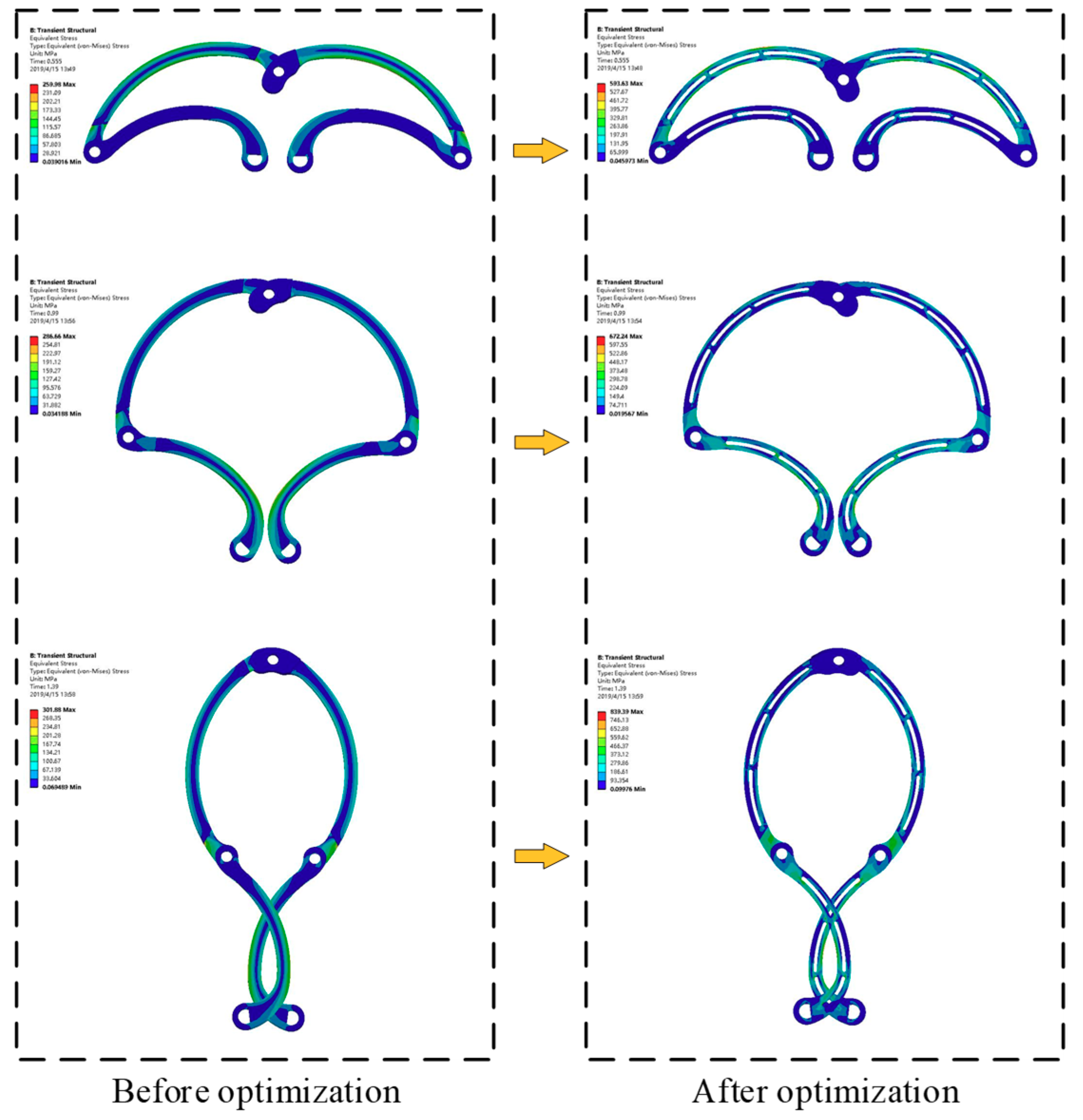
4.3. Structure Optimization of the Expanding Arm
5. Experiment
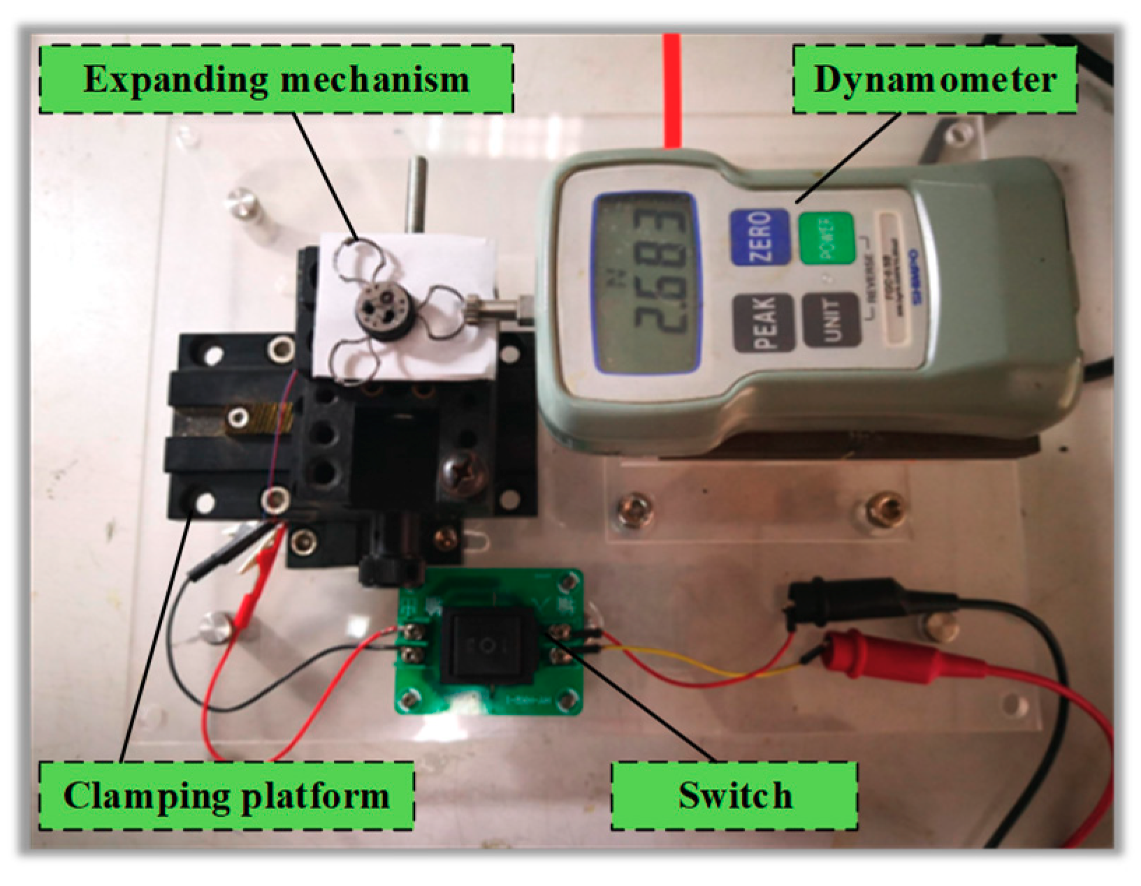
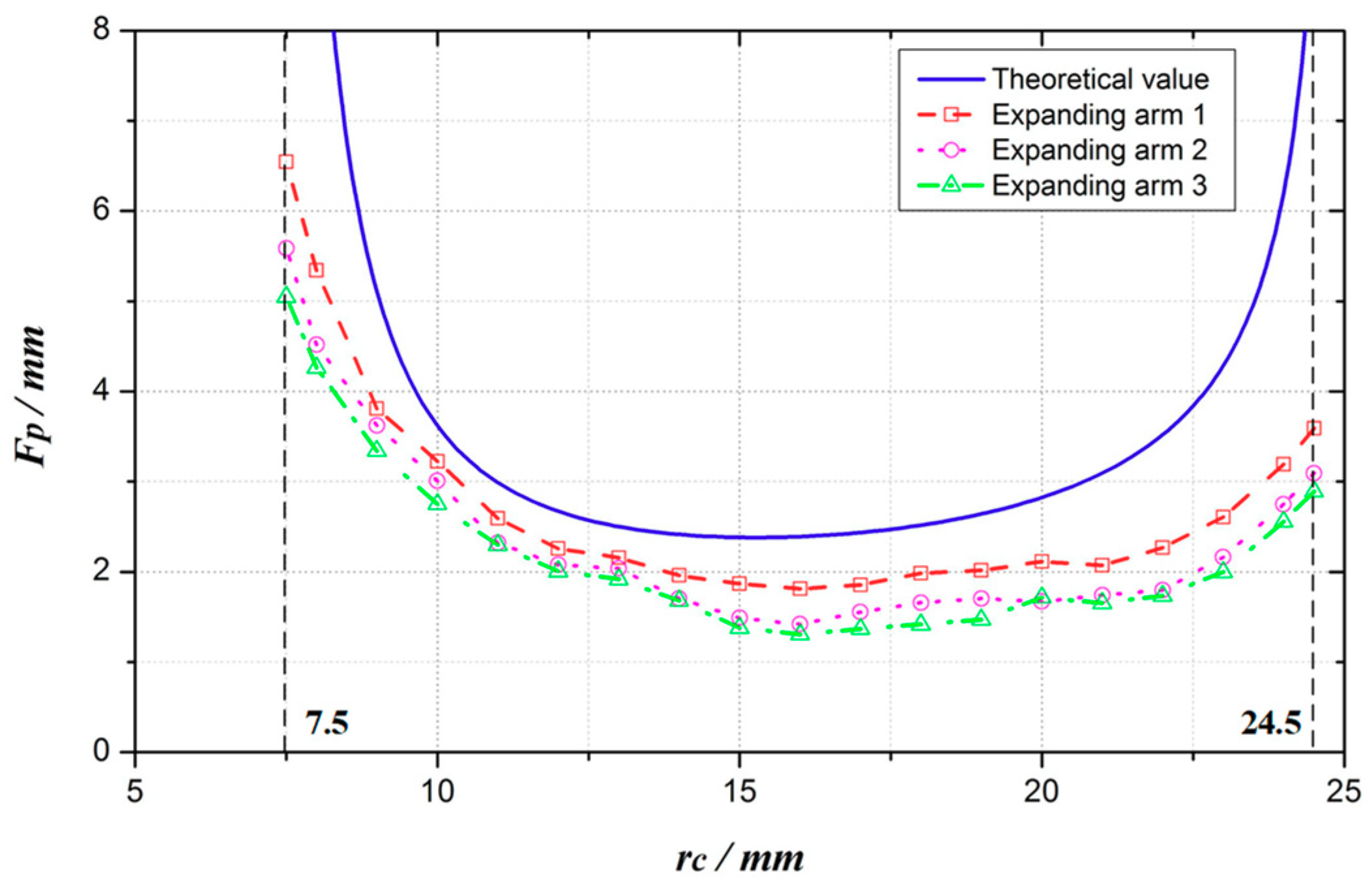
5.1. Expanding Force Test
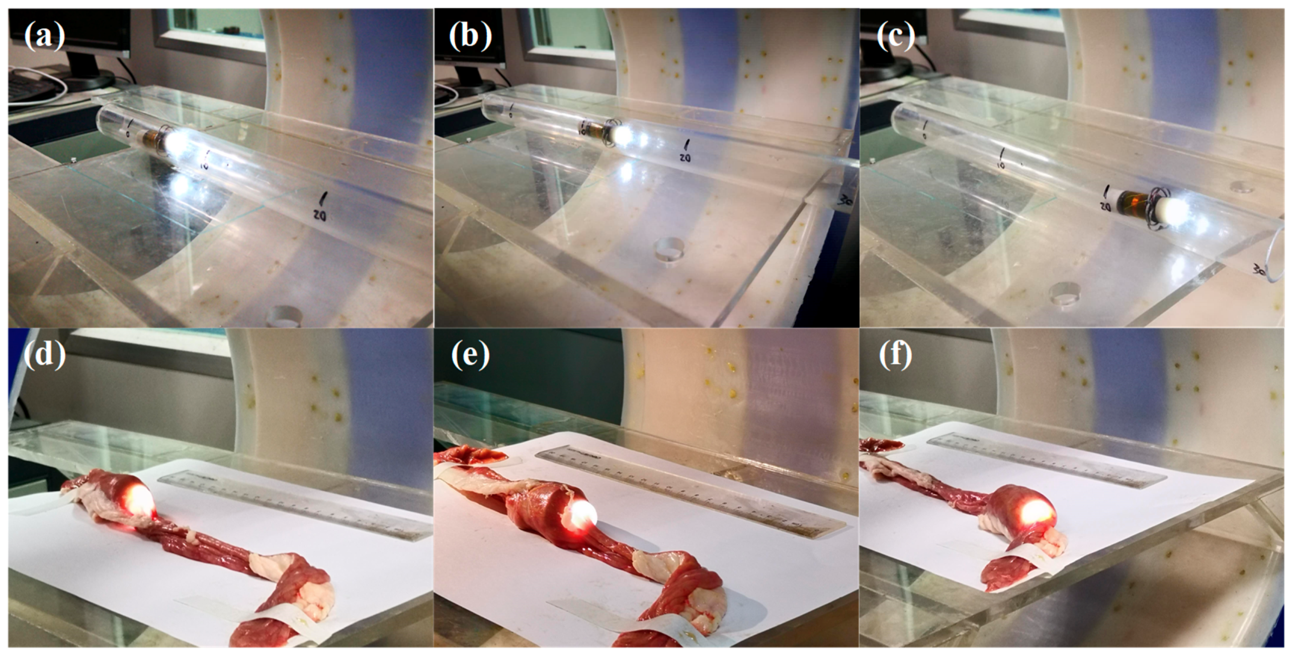
5.2. Locomotion Experiment
6. Conclusion
Author Contributions
Funding
Acknowledgments
Conflicts of Interest
References
- Siegel, R.L.; Miller, K.D.; Jemal, A. Cancer statistics 2019. CA A Cancer J. Clin. 2019, 69, 7–34. [Google Scholar] [CrossRef] [PubMed]
- Chen, W.; Zheng, R.; Baade, P.D.; Zhang, S.; Zeng, H.; Bray, F.; Jamel, A.; Yu, X.Q.; He, J. Cancer Statistics in China 2015. CA A Cancer J. Clin. 2016, 66, 115–132. [Google Scholar] [CrossRef] [PubMed]
- Stein, D.J.; Shaker, R. Complications of upper gastrointestinal endoscopy. Gastrointest. Emerg. 2016, 16, 43–50. [Google Scholar]
- Park, H.; Park, S.; Yoon, E.; Kim, B.; Park, J.; Park, S. Paddling based microrobot for capsule endoscopes. In Proceedings of the 2007 IEEE International Conference on Robotics and Automation, Roma, Italy, 10–14 April 2007; pp. 3377–3382. [Google Scholar]
- Kim, H.M.; Yang, S.; Kim, J.; Park, S.; Cho, J.H.; Park, J.Y.; Kim, T.S.; Yoon, E.-S.; Song, S.Y.; Bang, S. Active locomotion of a paddling-based capsule endoscope in an in vitro and in vivo experiment (with videos). Gastrointest. Endosc. 2010, 72, 381–387. [Google Scholar] [CrossRef] [PubMed]
- Zarrouk, D.; Shoham, M. Analysis and Design of One Degree of Freedom Worm Robots for Locomotion on Rigid and Compliant Terrain. J. Mech. Des. 2012, 134, 021010. [Google Scholar] [CrossRef]
- Kim, B.; Lee, S.; Park, J.; Park, J.-O. Design and Fabrication of a Locomotive Mechanism for Capsule-Type Endoscopes Using Shape Memory Alloys (SMAs). IEEE/ASME Trans. Mechatronics 2005, 10, 77–86. [Google Scholar] [CrossRef]
- Gorini, S.; Quirini, M.; Menciassi, A.; Pernorio, G.; Stefanini, C.; Dario, P. A Novel SMA-Based Actuator for a Legged Endoscopic Capsule. In Proceedings of the IEEE/RAS-EMBS International Conference on Biomedical Robotics and Biomechatronics, Pisa, Italy, 20–22 February 2006. [Google Scholar]
- Wang, W.; Yan, G.Z.; Wang, Z.W.; Gao, J.Y.; Jiang, P.P.; Liu, D.S.; Zhao, K. Design and optimization of expanding mechanism of intestinal robot. Opt. Precis. Eng. 2017, 25, 1815–1824. [Google Scholar]
- Simi, M.; Valdastri, P.; Quaglia, C.; Menciassi, A.; Dario, P. Design, Fabrication, and Testing of a Capsule With Hybrid Locomotion for Gastrointestinal Tract Exploration. IEEE/ASME Trans. Mechatron. 2010, 15, 170–180. [Google Scholar] [CrossRef]
- Yim, S.; Sitti, M. Design and rolling locomotion of a magnetically actuated soft capsule endoscope. IEEE Trans. Robot. 2012, 28, 183–194. [Google Scholar] [CrossRef]
- Zhang, Y.; Jiang, S.; Zhang, X.; Ruan, X.; Guo, D. A variable-diameter capsule robot based on multiple wedge effects. IEEE/ASME Trans. Mechatron. 2011, 16, 241–254. [Google Scholar] [CrossRef]
- Kim, J.Y.; Kwon, Y.C.; Hong, Y.S. Automated alignment of rotating magnetic field for inducing a continuous spiral motion on a capsule endoscope with a twistable thread mechanism. Int. J. Precis. Eng. Manuf. 2012, 13, 371–377. [Google Scholar] [CrossRef]
- Zhou, H.; Alici, G.; Than, T.D.; Li, W. Modeling and experimental investigation of rotational resistance of a spiral-type robotic capsule inside a real intestine. IEEE/ASME Trans. Mechatron. 2013, 18, 1555–1562. [Google Scholar] [CrossRef]
- Wang, K.D.; Yan, G.Z.; Jiang, P.; Ye, D. A wireless robotic endoscope for gastrointestine. IEEE Trans. Robot. 2008, 24, 206–210. [Google Scholar] [CrossRef]
- Valdastri, P.; Webster III, R.J.; Quaglia, C.; Quirini, M.; Menciassi, A.; Dario, P. A new mechanism for mesoscale legged locomotion in compliant tubular environments. IEEE Trans. Rob. 2009, 25, 1047–1057. [Google Scholar] [CrossRef]
- Woods, P.; Constandinou, T.G. Wireless capsule endoscope for targeted drug delivery: mechanics and design considerations. IEEE Trans. Biomed. Eng. 2013, 60, 945–953. [Google Scholar] [CrossRef]
- Sliker, L.J.; Kern, M.D.; Rentschler, M.E. An automated traction measurement platform and empirical model for evaluation of rolling micropatterned wheels. IEEE/ASME Trans. Mechatron. 2015, 20, 1854–1862. [Google Scholar] [CrossRef]
- Prendergast, J.M.; Formosa, G.A.; Rentschler, M.E. A Platform for Developing Robotic Navigation Strategies in a Deformable, Dynamic Environment. IEEE Robot. Autom. Lett. 2018, 3, 2670–2677. [Google Scholar] [CrossRef]
- Chen, W.; Yang, G.; He, S.; Ke, Q. Clamping mechanism of capsule endoscopes in intestine. Opt. Precis. Eng. 2013, 21, 1553–1560. [Google Scholar] [CrossRef]
- Chen, W.; Yan, G.; Wang, Z.; Jiang, P.; Liu, H. A wireless capsule robot with spiral legs for human intestine. Int. J. Med Robot. Comput. Assist. Surg. 2014, 10, 147–161. [Google Scholar] [CrossRef]
- Gao, P.; Yan, G.; Wang, Z.; Wang, K.; Jiang, P.; Zhou, Y. A robotic endoscope based on minimally invasive locomotion and wireless techniques for human colon. Int. J. Med. Robot. Comput. Assist. Surg. 2011, 7, 256–267. [Google Scholar]
- Yan, L.; Wang, T.; Liu, D.; Peng, J.; Jiao, Z.; Chen, C.Y. Capsule robot for obesity treatment with wireless powering and communication. IEEE Trans. Ind. Electron. 2015, 62, 1125–1133. [Google Scholar] [CrossRef]
- He, S.; Yan, G.Z.; Ke, Q.; Wang, Z.W. Design and experiment of an intestinal anchoring mechanism. Opt. Precis. Eng. 2015, 23, 102–109. [Google Scholar]
- Gao, J.Y.; Yan, G.Z. Locomotion analysis of an inchworm-like capsule robot in the intestinal tract. IEEE Trans. Biomed. Eng. 2016, 63, 300–310. [Google Scholar] [CrossRef] [PubMed]
- Gao, J.; Yan, G.; Wang, Z.; He, S.; Xu, F.; Jiang, P.; Liu, D. Design and testing of a motor-based capsule robot powered by wireless power transmission. IEEE/ASME Trans. Mechatron. 2016, 21, 683–693. [Google Scholar] [CrossRef]
- Zhou, H.; Alici, G.; Munoz, F. A magnetically actuated anchoring system for a wireless endoscopic capsule. Biomed. Microdevices 2016, 18, 102. [Google Scholar] [CrossRef]
- Zhou, H.; Alici, G.; Munoz, F. Frictional and Viscous Characteristics of an Expanding-Extending Robotic Endoscope in the Intestinal Environment. Tribol. Lett. 2015, 58, 36. [Google Scholar]
- Buselli, E.; Valdastri, P.; Quirini, M.; Menciassi, A.; Dario, P. Superelastic leg design optimization for an endoscopic capsule with active locomotion. Smart Mater. Struct. 2009, 18, 015001. [Google Scholar] [CrossRef]


| Parameter | Value | |
|---|---|---|
| Expanding Mechanism | Size (folded) | Φ15 × 6.5 mm |
| Size (expanded) | Φ49 × 6.5 mm | |
| VDR | 3.3 | |
| Reducer & Motor | Φ4 × 19.8 mm | |
| Reduction ratio | 1024 | |
| Parameter | Value |
|---|---|
| l1/mm | 8.50 |
| l2/mm | 10.70 |
| r0/mm | 5.66 |
| c/mm | 1.20 |
| ω/rad/s | 1.70 |
| rc /(mm) | |Δv|max/(mm/s) | |Δa|max/(mm/s2) |
|---|---|---|
| 7.5 | 4.81 | 587.00 |
| 8.5–9.7 | 0.80 | 158.81 |
| 22.8–24.0 | 0.94 | 189.97 |
| hi/(mm) | σmax/(Mpa) | σ[s]/(Mpa) |
|---|---|---|
| 1.2 | 428.50 | 864 |
| 1.0 | 510.94 | 864 |
| 0.8 | 917.02 | 864 |
| rc /(mm) | |Δv|max/(mm/s) | |Δa|max/(mm/s2) |
|---|---|---|
| 7.5 | 10.56 | 1478.39 |
| 8.5–9.7 | 1.53 | 589.32 |
| 22.8–24.0 | 2.32 | 566.00 |
© 2019 by the authors. Licensee MDPI, Basel, Switzerland. This article is an open access article distributed under the terms and conditions of the Creative Commons Attribution (CC BY) license (http://creativecommons.org/licenses/by/4.0/).
Share and Cite
Wang, W.; Yan, G.; Wang, Z.; Jiang, P.; Meng, Y.; Chen, F.; Xue, R. A Novel Expanding Mechanism of Gastrointestinal Microrobot: Design, Analysis and Optimization. Micromachines 2019, 10, 724. https://doi.org/10.3390/mi10110724
Wang W, Yan G, Wang Z, Jiang P, Meng Y, Chen F, Xue R. A Novel Expanding Mechanism of Gastrointestinal Microrobot: Design, Analysis and Optimization. Micromachines. 2019; 10(11):724. https://doi.org/10.3390/mi10110724
Chicago/Turabian StyleWang, Wei, Guozheng Yan, Zhiwu Wang, Pingping Jiang, Yicun Meng, Fanji Chen, and Rongrong Xue. 2019. "A Novel Expanding Mechanism of Gastrointestinal Microrobot: Design, Analysis and Optimization" Micromachines 10, no. 11: 724. https://doi.org/10.3390/mi10110724
APA StyleWang, W., Yan, G., Wang, Z., Jiang, P., Meng, Y., Chen, F., & Xue, R. (2019). A Novel Expanding Mechanism of Gastrointestinal Microrobot: Design, Analysis and Optimization. Micromachines, 10(11), 724. https://doi.org/10.3390/mi10110724