Article

Multiangular Observation of Canopy Sun-Induced Chlorophyll Fluorescence by Combining Imaging Spectroscopy and Stereoscopy

1
Institute of Bio- and Geosciences, IBG-2: Plant Sciences, Forschungszentrum Jülich GmbH, 52428 Jülich, Germany
2
Global Wheat Program, International Maize and Wheat Improvement Center (CIMMYT), 56237 Texcoco, Mexico
3
INRES-Plant Breeding, University of Bonn, 53115 Bonn, Germany
4
Experimental Station of University of Bonn in Klein-Altendorf, 53359 Rheinbach, Germany
*
Author to whom correspondence should be addressed.
Remote Sens. 2017, 9(5), 415; https://doi.org/10.3390/rs9050415
Submission received: 16 February 2017 / Revised: 19 April 2017 / Accepted: 23 April 2017 / Published: 28 April 2017

Abstract

:
The effect that the canopy structure and the viewing geometry have on the intensity and the spatial distribution of passively measured sun-induced chlorophyll fluorescence at canopy scale is still not well understood. These uncertainties constrain the potential use of fluorescence to quantify photosynthesis at this level. Using a novel technique, we evaluated the diurnal changes in the spatial distribution of sun-induced fluorescence at 760 nm (F760) within the canopy as a consequence of the spatial disposition of the leaves and the viewing angle of the sensor. High resolution spectral and stereo images of a full sugar beet canopy were recorded simultaneously in the field to estimate maps of F760 and the surface angle distribution, respectively. A dedicated algorithm was used to align both maps in the post-processing and its accuracy was evaluated using a sensitivity test. The relative angle between sun and the leaf surfaces primarily determined the amount of incident Photosynthetic Active Radiation (PAR), which in turn was reflected in different values of F760, with the highest values occurring in leaf surfaces that are perpendicularly oriented to the sun. The viewing angle of the sensor also had an impact in the intensity of the recorded F760. Higher viewing angles generally resulted in higher values of F760. We attribute these changes to a direct effect of the vegetation directional reflectance response on fluorescence retrieval. Consequently, at leaf surface level, the spatio-temporal variations of F760 were mainly explained by the sun–leaf–sensor geometry rather than directionality of the fluorescence emission. At canopy scale, the diurnal patterns of F760 observed on the top-of-canopy were attributed to the complex interplay between the light penetration into the canopy as a function of the display of the various leaves and the fluorescence emission of each leaf which is modulated by the exposure of the individual leaf patch to the incoming light and the functional status of photosynthesis. We expect that forward modeling can help derive analytical simplified skeleton assumptions to scale canopy measurements to the leaf functional properties.

Graphical Abstract

1. Introduction

Understanding the dynamic changes of canopy photosynthesis is crucial for many scientific disciplines. However, the quantification of photosynthetic activity at this scale is typically constrained by the spatio-temporal variation of regulatory properties, such as light intensity and photosynthetic pigments. In recent years, the measurement of sun-induced chlorophyll fluorescence has been strongly developed as a promising tool to directly quantify photosynthesis over various scales [1,2,3,4]. Further, the use of imaging techniques for the retrieval of sun-induced fluorescence offers new possibilities to obtain spatial information on the distribution of photosynthetic activity while accounting for the variability of environmental factors and intrinsic properties of the vegetation.
Fluorescence is emitted by the photosynthetic apparatus under the prevailing light conditions and is directly linked to natural or stress-related changes of photosynthetic electron transport rate in green leaves [5,6,7]. Characterized by two peaks of emission around 685 nm (red fluorescence peak) and 740 nm (far-red fluorescence peak) [8,9], chlorophyll fluorescence can be passively retrieved using the Fraunhofer Line Depth (FLD) principle applied mainly in the O2-A and O2-B atmospheric absorption bands [10,11,12,13,14]. Reported measurements of sun-induced fluorescence from ground [15,16,17], airborne [18,19,20] and spaceborne [21,22,23] sensors have proven the feasibility of retrieving this signal on top-of-canopy (TOC), providing new insights on the spatial distribution of vegetation fluorescence across a wide range of spatial scales, ranging from single leaves to the ecosystem scales. Despite these achievements, there are still uncertainties related to the effect that canopy structure and the observation geometry may have on the intensity of fluorescence emission that is recorded at canopy level, limiting partly the capability to link large scale measurements with leaf photosynthesis and the actual physiological status of the vegetation [13,24,25]. Although it is generally accepted that fluorescence is emitted isotropically at the leaf surface, structural characteristics at leaf and canopy level can affect not only the directionality of the fluorescence emission at TOC but also the correct estimation of the parameters used in the FLD method for its retrieval. Consequently, understanding the effect of canopy structure on the distribution of light, plant photosynthesis and fluorescence emission within the canopy is a critical issue, particularly when sun-induced fluorescence is measured at coarse spatial resolution.
The canopy structure has a great impact on the light distribution within the canopy. While the sun position is the primary factor determining the irradiance at TOC, the orientation and the arrangement of the leaves determine the interception, distribution, and the quality of the radiation within the canopy [26,27]. This interaction results in heterogeneous light environments that lead to quick and unpredicted variations of photosynthetic activity, which in turn influence substantially the spatio-temporal distribution of fluorescence emission [27,28,29]. Furthermore, the spatial distribution of the canopy elements has an impact in the re-absorption, re-emission, and scattering of fluorescence within the canopy. This leads to a non-linear relation between the total fluorescence emitted by individual leaves and the fluorescence detected at TOC [30,31]. This multi scattering is wavelength dependent and thus affects the two fluorescence peaks differently. As a first approximation, it is assumed that the red fluorescence peak is strongly re-absorbed within the canopy, while the far-red fluorescence is mainly transmitted [7,32]. Available integrated leaf-canopy models such as the Fluorescence Model (FluorMOD) [33] and the Soil Canopy Observation, Photochemistry and Energy fluxes model (SCOPE) [34] can model these processes while considering the canopy structure. These models currently represent the only way to quantify the relationship between the detected signal at TOC and the factors that regulate its emission at leaf level. However, their schemes to integrate light environment, leaf display, fluorescence emission, and photosynthesis in this complex 3D matrix still have to be validated.
Spatially resolved measurements of sun-induced fluorescence over canopies can be of great help to understand the interplay between canopy structure and the distribution of fluorescence emission. However, only few studies have exploited this potential. For instance, Zarco-Tejada et al. [35] used fine resolution airborne images to evaluate the impact of pixel aggregation of different tree canopy components on the capacity of sun-induced fluorescence to predict stomata conductance at leaf level. Damm et al. [24] analyzed the level of retrieval errors in high resolution observations associated to heterogeneous illumination and inaccurate assumptions of direct and diffuse surface irradiance. Recently, Pinto et al. [15] were able to evaluate spatio-temporal variations of fluorescence emission for single elements of canopies under field condition using imaging spectroscopy. These studies highlight the importance of the canopy structure parameterization for improving the interpretations of passively retrieved sun-induced fluorescence into photochemistry and thus validate the existing models. They identify important aspects related to the canopy structure that constrain the actual retrieval of canopy sun-induced fluorescence. That is the case of the canopy anisotropy and proper estimations of surface irradiance, both determined partly by the relative angle between the sun, leaf surfaces and sensor position.
Integrating fluorescence measurements with detailed spatial information of the canopy structure has not yet been explored. The 3D reconstruction of a canopy is not straightforward, especially under field conditions. Irregularities of leaf surfaces and shapes, overlapping between neighboring plants and mechanical movements produced by wind are among the factors that make accurate 3D reconstructions challenging. In the past years few methodologies, including structured light approaches [36], stereo imaging [37,38] and laser scanning techniques [39,40], have become available to estimate plant structural traits including leaf angle distribution. In particular, stereo imaging has been referred as a rapid and easy approach to characterize the outer canopy leaves, providing a good compromise between accuracy and versatility in the field [38,41]. The integration of this kind of data with spectral information represents a potential tool to address issues related with the effect of canopy structure on canopy fluorescence emission and photosynthesis. However, this has not yet been explored.
In this study, we assess the feasibility and the potential of combining simultaneous measurements of ground-based imaging spectroscopy and stereo imaging to evaluate the diurnal spatio-temporal distribution of the fluorescence emission in a sugar beet outer canopy while taking into account the effect of varying leaf orientation. We aim to assess the impact that the leaf surface characteristics and the spatial distribution of leaves within the canopy have on the level of fluorescence detected on TOC. A novel approach is introduced, where detailed canopy fluorescence maps are aligned pixel-wise with maps containing information on the surface zenith and azimuth angles. Sun-induced fluorescence was retrieved at 760 nm using the FLD principle in the O2-A band, whereas for the 3D canopy reconstruction stereo images were acquired with two commercial DSLR cameras. The accuracy of the co-registration was evaluated visually and through a sensitivity test. The collected data allowed having information from a wide range of leaf surfaces and view angles, although the static nature of the setup did not cover all possible angle combinations existing within the canopy. Our results provide new insights on the directionality of fluorescence as a result of the interplay between the leaf surface, the inclination and orientation of the leaves, the angle of the solar beam and the angle of observation.

2. Materials and Methods

2.1. Plant Material

Diurnal changes in spatial distribution of sun-induced fluorescence emission were investigated in a fully developed sugar beet canopy (Beta vulgaris L. cv Pauletta). Plants were sown on 28 March 2012 with a density of 10 seeds/m2 and grown under normal field conditions. Measurements were performed on 25 July at the growing stage 39 of the extended BBCH scale [42]. The experiment took place at the Experimental Campus Klein-Altendorf (University of Bonn, Germany, 50°37′24.6″N 6°59′11.2″E) as part of the central experiment of the CropSense.net project (www.cropsense.uni-bonn.de).

2.2. Measuring Set Up and Data Acquisition

Two different imaging systems were used simultaneously to estimate the emission of fluorescence and to reconstruct the 3D structure of the canopy. The first one was an imaging spectroscopy system used to derive sun-induced fluorescence. It consisted of a commercial push broom hyperspectral camera for the visible/near infrared (VIS/NIR) part of the spectrum (PS V10E, Specim Inc., Oulu, Finland) with a full-width-half-maximum (FWHM) of approximately 3.8 nm in the NIR and a spectral sampling interval of 0.63 nm. The camera had a 23 mm focal length optics with a field of view (FOV) of 22.09° and a sensitive high-speed interlaced CCD detector with a full frame of 1392 spatial samples by 1040 spectral bands (for more details, see [15]). The camera was operated with a hardware spatial binning of 2 (694 pixels) in order to improve the signal-to-noise ratio. During acquisition the camera was pointing in nadir position and moved horizontally at constant speed using a motorized scanning bar of one meter length (BiSlideTM 40″, Velmex Inc., Bloomfield, NY, USA).
The second system was a stereo camera setup used to derive the 3D surface model of the canopy and to calculate the zenith and azimuth angles for each vegetation surface represented by a pixel. This system consisted of two commercial digital single-lens reflex cameras (Canon EOS 5DMark II) equipped with 50 mm lenses and aligned in a fixed geometry with a baseline of approximately 200 mm between them (for details, see [41]). Both cameras were pointing to the target in nadir direction. The auto-focus mode was used to focus the vegetation and then it was disabled during actual data acquisition to ensure simultaneous exposure of both cameras, which is essential to avoid effects from natural movements of the canopy. The cameras were triggered via a remote-control release.
Both imaging systems were mounted in a cherry picker to acquire data simultaneously from 3.5 m above the canopy (Figure 1). The use of this kind of platform enabled us to reach homogenous parts of the canopy. In order to avoid obstructions, the stereo rig was fixed approximately 10 cm behind and 20 cm below the hyperspectral camera and aligned to the middle of the scanning bar. The swath of the hyperspectral camera was about 1.4 m with a pixel size at target level of 2 mm whereas the stereo imaging setup covered a larger area with pixel size of 0.45 mm at target level. The acquisition time for one spectral image was approximately 40 s while a stereo image recording was instantaneous. Five stereo images were acquired for each spectral image and the best match was selected during the processing. The data were acquired over the same canopy spot in intervals of about 1 h for a period of 5 h centered around solar noon (1:30 p.m. local time) under clear sky conditions. To facilitate the co-registration of both systems in the post-processing, 8 pink markers were located at the top-of-canopy level and within the region covered by both sensors.

2.3. Pre-Processing of the Imaging Spectroscopy Data

Systematic offsets caused by the dark noise were corrected in the imaging spectroscopy data using pre-acquired dark current readings obtained by closing the camera shutter under actual measurement conditions. Pixels showing saturation at any wavelengths were masked out to avoid miscalculations in subsequent processing steps. Raw data values were then converted to radiance (mW m−2 sr−1 nm−1) using a linear radiometric calibration coefficient estimated for each pixel of the detector and provided by the camera manufacturer. The radiance data were used for the estimation of the irradiance of photosynthetic active radiation on top-of-canopy (PARTOC) and the fluorescence. PARTOC was quantified from the radiance measurements over a calibrated reflectance panel located in each scene (20% Spectralon®, Labsphere Inc., North Sutton, NH, USA). Assuming a Lambertian reflectance behavior of the panel, measured radiance values were multiplied by π to approximate hemispherical irradiance [43,44]. Finally, incoming PARTOC was calculated in W m−2 by integrating the irradiance between 400 and 700 nm.

2.4. Retrieval of Sun-Induced Chlorophyll Fluorescence

The passive retrieval of sun-induced fluorescence relies in the possibility to decouple this signal from the solar radiation that is reflected by the vegetation while taking into account the characteristics of the atmospheric path between vegetation and sensor. The methods based in the FLD principle achieve this by using spectral regions where the incoming solar radiation is strongly diminished by the oxygen in the atmosphere, particularly the O2A-band at 760 nm and the O2B-band at 687 nm. In these regions the contribution of fluorescence emission to the overall vegetation radiance increases, facilitating its detection [10,13,45]. In this study we used the imaging spectroscopy data and the improved version of the FLD method (iFLD) proposed by Alonso et al. [14] to quantify the sun-induced fluorescence at 760 nm (F760). We exploited the O2-A absorption feature, which is wide and deep enough for reliable remote quantification of fluorescence given our sensor spectral resolution [12,15,46].
The vegetation radiance detected by the sensor (L) for two wavelengths, inside (i) and outside (o) the O2A-band, can be expressed as:
L j = L j p + ( E j g ρ j π + F j ) T j 1 S j ρ j , j = i , o
where Lp accounts for the path scattered radiance, Eg is the global irradiance arriving on the surface (i.e., including direct and diffuse fluxes), ρ is the surface reflectance, F is the emitted sun-induced fluorescence, T is the upward atmospheric transmittance and S is the spherical albedo of the atmosphere. Assuming that ρ and F are Lambertian, and that Eg is isotropic, the atmospheric parameters (i.e., Eg, Lp, S, and T↑) can be calculated at canopy level using MODTRAN5® (Spectral Sciences, Inc., Burlington, MA, USA and the Air Force Research Laboratory, Wright-Patterson AFB, OH, USA) according to Guanter et al. [47]. Hence, the system in Equation (1) contains four unknowns: the spectral reflectance and fluorescence values, inside and outside of the absorption band (ρi, ρo, Fi, and Fo).
The terms ρ and F inside and outside the absorption feature are related by the coefficients A and B:
ρ o = A ρ i F o = B F i }
With A and B estimated according to Alonso et al. [14], the fluorescence inside the O2-A band can be calculated using Equations (1) and (2) as:
F i = A X i ( E o g + X o S o ) X o ( E i g + X i S i ) A ( E o g + X o S o ) B ( E i g + X i S i )
where
X j = ( L j L j p ) T j , j = i , o
and
E j g = 1 π ( E j g ) , j = i , o
The atmospheric parameters were simulated assuming middle latitude summer atmospheric conditions, rural aerosol model, and a visibility of 23 km. The irradiance was estimated for a flat surface. Given the short distance between sensor and target the product of S and ρ can be assumed as <1 and therefore S was set to zero. Furthermore, Lp was also assumed zero for the same reason. The rest of the simulated parameters were spectrally resampled to meet our sensor configuration taking into account the across-track spectral shift and FWHM [46,48]. Inaccuracies and uncertainties in the atmospheric and sensor characterization were compensated using the effective transmittance correction (ETC) method [49,50]. In this approach, values of T inside the O2-A are adjusted across-track using a simple correction coefficient that is calculated from pixels with known fluorescence (i.e., F760 = 0; for details, see [15]). In this study, we used pixels from the reference panel and a grey board that covered the whole across-track section and was located on one side of each scene.
Only the spectral subset of the data between 726 nm and 815 nm was used for the retrieval of F760. The values of all parameters outside the absorption band (i.e., subscript o) were calculated averaging 5 adjacent spectral bands outside the absorption feature to reduce sensor noise. The values for the subscript i were chosen from the band showing the lowest radiance inside the absorption feature.

2.5. Canopy 3D Reconstruction and Leaf Angle Estimation

The estimation of the orientation of a surface represented by a pixel in the F760 maps required the previous 3D reconstruction of the canopy. This was achieved using the stereo imaging data and the software toolbox developed by Müller-Linow et al. [41], which computes the surface of each leaf from a disparity map. The algorithm can be summarized in five basic steps: calibration of the stereo camera setup, correspondence analysis, 3D point cloud generation, leaf segmentation, and leaf surface reconstruction. In the following, we give a brief summary of these processing steps. A detailed description of this processing pipeline is given in [41].
In a first calibration step, camera geometries and the geometry of the stereo rig were estimated. Images were rectified based on the stereo calibration, and a correspondence analysis was applied on rectified images using a block statistics method based on Pearson correlation coefficients. A disparity map was obtained by calculating the relative position of the corresponding points. At this stage, a series of filters were applied in order to detect and eliminate pixels showing wrong disparity estimates. The disparity map was converted to a 3D point cloud, which was further processed by a series of segmentation and fitting steps that ultimately produced a 3D triangular leaf surface mesh. Finally, the orientation of each resulting leaf face was expressed in the spherical coordinate system by the zenith ( φ l ) and azimuth ( θ l ) of the leaf surface normal in respect to the nadir position. In essence, this procedure is robust and allows a surface reconstruction of the outer canopy with high spatial resolution.

2.6. Image to Image Registration

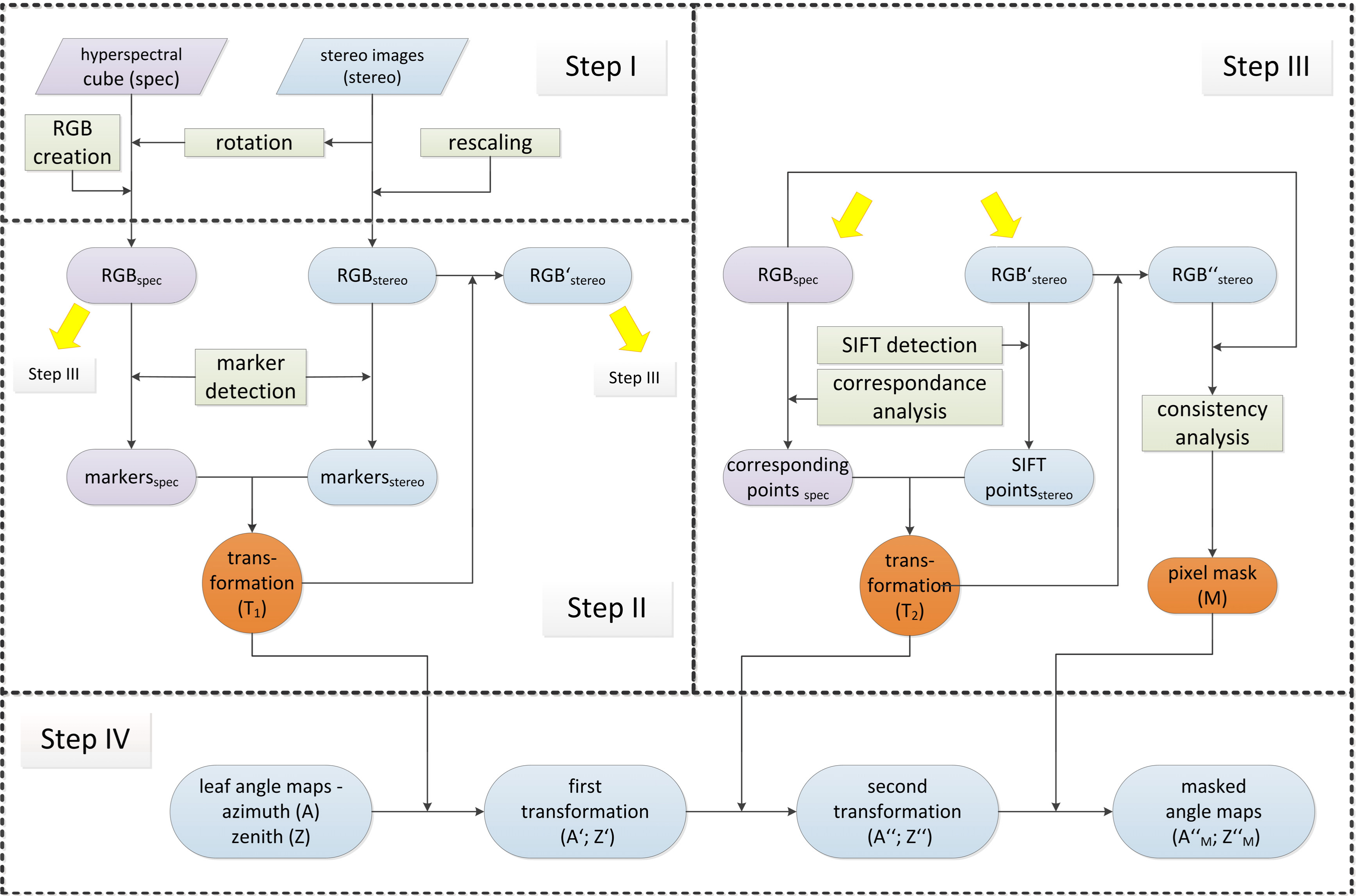
The two imaging systems had different viewing geometries resulting in spatial misalignment between their outputs. Conventional alignment methods, which use key point features such as SIFT, cannot be applied directly for the registration of both data types due to their different nature [51]. Therefore, a four-step alignment algorithm was developed to co-register the outputs of both sensors (Figure 2). This approach relied in a first rough alignment using field markers, which later allowed the registration via a combination of SIFT and block matching.

Step I: Selection of RGB images from stereo imaging and imaging spectroscopy data:

The alignment algorithm required a RGB representation of both datasets to facilitate a proper registration. These RGB images were used to compute the transformation matrices, which were then applied to the leaf angle maps (see step IV). The RGB image from the left camera of the stereo camera setup was selected (RGBstereo). In the case of the imaging spectroscopy data, the RGBspec was created using three bands at 638.8 nm (red), 549.5 nm (green), and 459.0 nm (blue). In the current acquisition setup, the hyperspectral camera produced flipped images in respect to the actual orientation of the scene. Taking the RGBstereo as reference, RGBspec images were first transformed applying image rotation and an axis mirroring. To facilitate the detection of the field markers in both images (markersstereo and markersspec) the RGBstereo was resized so that the resolution of RGBstereo and RGBspec were approximately the same. The same scaling factor was applied for all the set of images. The results were visually checked.

Step II: Projective image transformation of RGBstereo using field markers:

The pink color of the markers provided a good contrast against the dominantly green background and ensured homogeneous surfaces that could be detected automatically using the known marker size and image thresholding in the three channels of the HSV color space, which can easily be derived from RGB color values. A first step in the detection of the markers required 6 parameters defining a lower and upper threshold for each HSV channel (i.e., H-hue, S-saturation and V-value). Only pixels with values within these ranges were identified as potential marker pixels. The thresholds were adjusted manually and the results checked visually. Additionally, gaps were closed in the detected surfaces. Once the right thresholds were set for one of the images, the values were applied for the rest of the dataset. This last procedure showed to be consistent as long as the illumination conditions did not change substantially. A second step assumed that the markers were the largest objects displayed in both RGB images under the defined HSV properties. False positives—i.e., pixels or pixel clusters that did not belong to any marker but display similar HSV values—were removed if they were below a particular cluster size. Finally, the center of each marker was determined by the balance point of each pixel cluster and automatically labeled using the same order for both RGB images.
The position of the field markers was then used for the computation of a projective transformation (T1) of RGBstereo to RGB′stereo. The relative marker positions of the resulting image should be identical to those of the RGBspec.

Step III: Fine canopy alignment using image key points and block matching:

Fine alignment was accomplished by means of SIFT features [51] and resulting key points. SIFT points were only extracted from RGB′stereo and the corresponding key points in RGBspec were detected with block matching using correlation statistics on the value channel from the HSV color space [52]. Since both images were roughly aligned at this step, the searching range for block matching was reduced to a small region around each key point. A block size of 21 × 21 pixels was used to find the corresponding pixel in the RGBspec. Blocks from both RGB images were compared by applying correlation statistics. Those pixels with a block statistics showing a correlation coefficient >0.85 were considered as corresponding pixels. A fairly large amount of pixel pairs (>1000 pairs) were detected for each measuring time. Corresponding pixels were finally used to compute a new spatial transformation (T2) of RGB′stereo into RGB″stereo. We tried different transformation types. Based on visual inspections and a sensitivity test (see Section 3.1), a third degree polynomial transformation resulted in the best matching between RGBspec and RGB″stereo.

Step IV: Detection and masking out of non-matching pixels:

Despite the sequence of transformations applied in the previous steps, at this point images still showed substantial differences related to image content, perspective and leaf movement due to wind during the IS acquisition. Therefore, each pixel in the RGBspec was checked with an additional block filter, which defined a threshold for the correlation between corresponding blocks in the hue channel. We found that the computed correlation coefficients, even though they were very small, could be used for comparing both images. Hence, pixels showing a correlation coefficient below 0.15 were removed in both images.

2.7. Estimation of Sun and Camera Viewing Incidence Angles

The incidence angle of the solar radiation and the camera viewing vectors in respect to the leaf surface normal represented by a pixel ( φ s i n and φ c i n respectively), were calculated using:
φ v i n = arccos [ cos φ l cos φ v + sin φ l sin φ v cos ( θ l θ v ) ] , v = s , c
where φ s and θ s are the zenith and azimuth angle of the sun rays, respectively; and φ c and θ c are the zenith and azimuth of the camera viewing vector with respect to the ground normal, resectively. The sun position was calculated for each scene using the “sun position tool” implemented in MODO (ReSe Applications Schläpfer, Switzerland). The camera viewing angle with respect to the ground normal was calculated for each pixel in the across-track direction. For this, the instantaneous field of view of each pixel ( i F O V p i x e l = F O V / n r . o f   a c r o s s _ t r a c k   p i x e l s ) was used to estimate the camera viewing angle at a particular position. The central pixel was assumed to be at nadir position. Since the imaging spectroscopy system was oriented from north to south during the measurements, the θ c of half of the pixels across track was assumed to be 180° while for the other half was 0°.
The combined effect of φ s i n and φ c i n on the retrieved F760 was evaluated. Additionally, the φ s i n was used to parameterize MODTRAN5® and simulate the incident PAR for each vegetation pixel according to the surface inclination.

2.8. Sensitivity Test

Given the nature of our data, there was not a simple way to evaluate the accuracy of our co-registration approach. The visual inspection could only provide a general impression whether the co-registered maps correspond to each other. A more quantitative approach was achieved by observing the relationship between the pixels reflected radiance at a given wavelength ( L λ ) and φ s i n . A simplified version of Equation (1) can be used to model this relationship:
L λ = 1 π [ E λ d i f + E λ d i r cos ( φ s i n ) ] ρ λ T j
where Edif and Edir represent the diffuse and direct irradiance respectively. These variables were estimated using MODTRAN5®. The reflectance ( ρ ) was estimated from pixels with a φ l lower than 5°. The variables Lp, S, and F were neglected for simplification. It is worth noting that this model assumes Lambertian reflection of the vegetation and nadir observation.
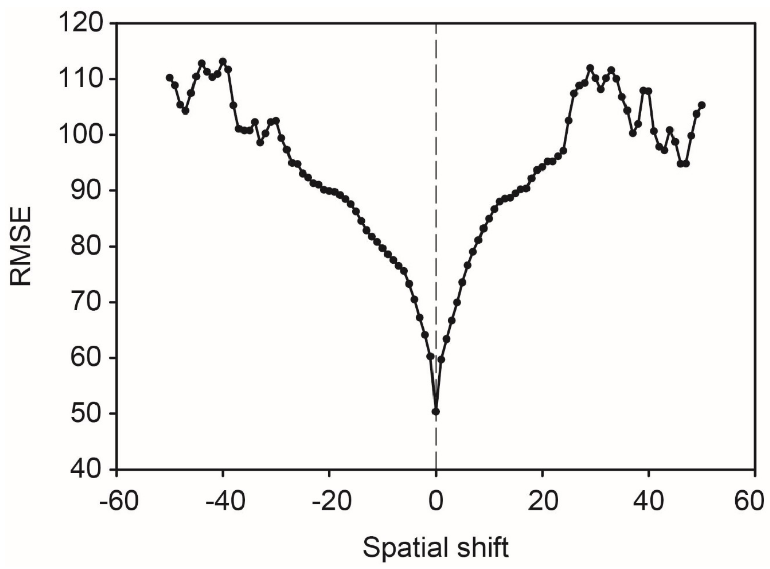
For a sensitivity test, the actual radiances at 757 nm were compared against modeled radiances at successive steps where spatial shifts were applied to the angle maps. The angle maps were shifted in the x- and y-axes by one pixel at a time. Higher accuracy in the co-registration should result in lower root-mean-squared error (RMSE) while disperse values would denote an inaccurate image to image registration.

2.9. Data Analysis

Canopy F760 was obtained by integrating the F760 values of all the vegetation pixels in each the hyperspectral images (i.e., including sunlit and shaded surfaces). On the other hand, the effect of the leaf orientation on the spatio-temporal patterns of F760 within the canopy could be evaluated only using the subset of pixels where the surface angle was available and that were not shaded by upper layers (for details on the selection of these pixels see Section 3.1). These pixels represented nearly 25% of all the pixels encompassing the canopy. For this multiangular analysis, F760 values were averaged using the median over 5° sampling intervals for both φ l and θ l . This reduced the amount of data and accounted for noise coming from the imaging systems and the data processing. Pixels with φ l higher than 80° were excluded since uncertainties are high in the 3D reconstruction for nearly vertical surfaces. Leaves borders were also removed from the analyses to avoid the effect of spectral mixing between vegetation and the background. Finally, pixels located under shadow conditions were masked out using a semi-automated classification based on brightness thresholds. To this end, RGBspec images were converted into the HSV color space and classification thresholds for the value channel were adjusted manually while inspecting visually the results.

3. Results

3.1. Assessment of the Image to Image Registration Approach

The rosette architecture of the sugar beet plants provided a canopy model without a complex multilayer structure and with a wide range of φ l and θ l . The roughness of the leaves surface contributed to increase the frequency and the range of angles of vegetation surfaces in relation to the sun, resulting in scenes with heterogeneous light conditions that demanded a precise co-registration.
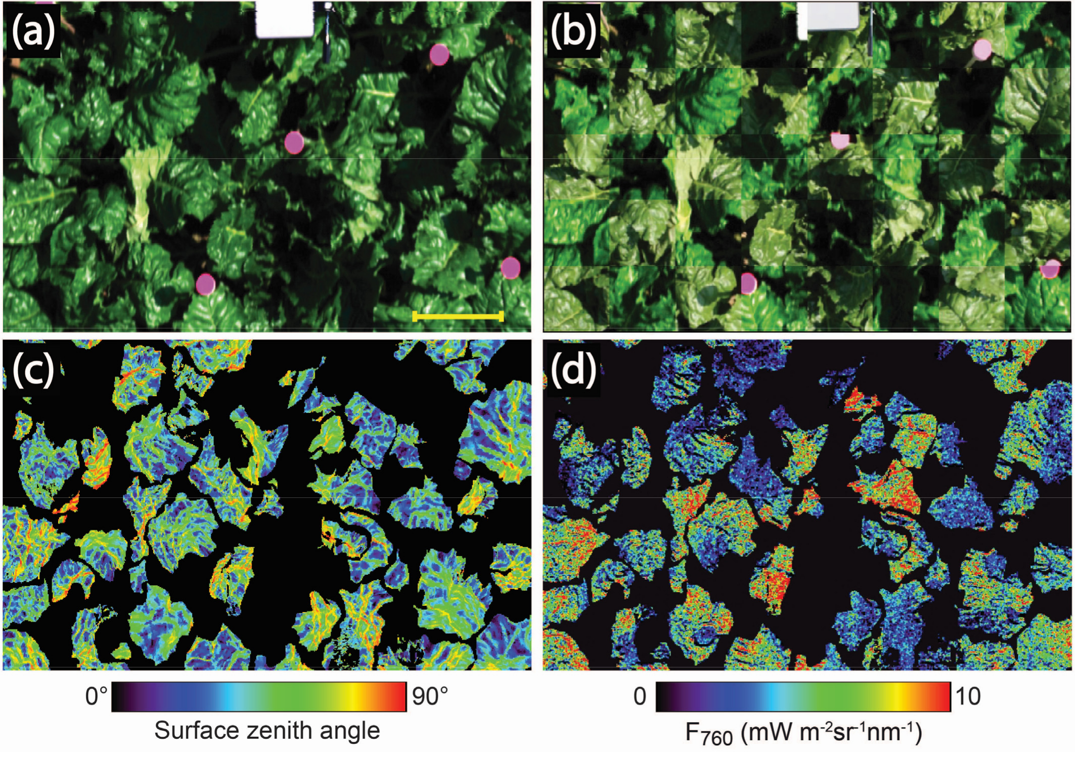
An example of an RGBspec and the corresponding F760 and φ l maps are given in Figure 3. The φ l and θ l could be retrieved for about 30% to 40% of the total pixels of each imaging spectroscopy data, from which approximately 80% to 90% showed a good correlation between the corresponding pixels of the two imaging systems. This was partly due to the series of filters, transformations, and segmentation to which the stereo imaging data were subjected. Despite this, the visual inspections showed a good alignment between the transformed RGB″stereo images from and the RGBspec (Figure 3b).
Within those vegetation pixels showing a good correlation between the two imaging systems, three different clusters could be distinguished when plotting the radiance as a function of the φ s i n (Figure 4a). At 757 nm, around 60% of the pixels showed a clear decrease of the reflected radiation with higher φ s i n (red class in Figure 4a). These pixels corresponded to surfaces where the incoming radiation is not affected by upper leaves. They were mostly sunlit leaf surfaces. However, this group also included surfaces exposed only to diffuse radiation as a consequence of their oblique angle to the solar beam (For the rest of this article we will refer to this group as pixels from class 1). A second group of pixels showed constant low radiances regardless of the leaf inclination (blue class in Figure 4a). They commonly corresponded to surfaces deeply shaded by other leaves. This group represented about 20% of the pixels. The third class corresponded to the rest of the pixels which showed no correlation between their radiance and their orientation to the sun (yellow class in Figure 4a). Interestingly, most of these pixels were found in leaf veins, where the high brightness hindered the 3D reconstruction. The segmentation of the pixels into the different classes was achieved by a simple manual selection of the clusters observed in the 2D scatter plot of Figure 4a. The second and third class of pixels were excluded from the analysis of the F760 distribution as a function of leaf orientation and inclination. However, they were considered for the estimation of F760 of the whole canopy.
The relationship observed between φ s i n and the reflected radiance in pixels from class 1 (i.e., red class) tended to disappear after applying successive spatial shifts to the angle maps as a sensitivity test (Figure 4). A shift of five pixels resulted already in an increase of the data dispersion (Figure 4b), whereas no relationship was observed after a 40 pixels shift. Figure 5 represents the variation of the RMSE between observed and predicted values of reflected radiance as a function of the spatial shift applied. It can be seen that the primary output of the image to image registration algorithm (i.e., spatial shift = 0) had actually the smallest RMSE. A rapid increase of the RMSE was observed after applying a shift of only one pixel. After a shift of approximately 30 pixels, the RMSE almost doubled the initial value.

3.2. Leaf Angle Distribution of the Canopy

The stereo images provided information on the leaf angle distribution of the studied canopy. Figure 6 shows the distribution of the inclination and orientation of all leaf surfaces that were possible to reconstruct from the stereo imaging, regardless of their correlation with RGBspec. The distribution of φ l and θ l did not show significant variations over the day (data not shown). Figure 6 represents the leaf angle distribution expressed in terms of leaf surface for the data recorded at midday. It can be observed that most of the surfaces had a φ l higher than 45° (Figure 6a). Surfaces with φ l between 60° and 70° represented the largest area of the outer canopy (~30%), while flat surfaces (i.e., φ l <20°) account for less than 12%. The polar plot in Figure 6b illustrates the two-dimensional histogram where the radial and angular axes represent φ l and θ l , respectively. This plot reveals that the surface distribution as a function of the θ l angle was not uniform. The largest proportion of leaf surfaces were facing in directions that coincided with the diurnal trajectory of the sun, especially towards the southeast and southwest (Figure 6b).

3.3. Variations of F760 as a Function of the Sun and Viewing Incidence Angle

Similar to the reflected radiation, the values of F760 showed a high dependency on the incident angle of the solar radiation. A significant linear correlation was observed between F760 and the cosine of φ s i n in leaf surfaces belonging to the class 1 (Figure 7). However, fluorescence was not zero when the angle between the solar radiation and the leaf surface was at minimum. This indicates a background flux of photons that is also observed in leaf surfaces under shadow conditions (i.e., pixels from class 2) where the correlation between F760 and φ s i n was not significant (Figure 7b). This background flux can have two sources. The first is some fluorescence signal coming from adjacent pixels and the second would result from a deficient characterization of the scatter path radiance ( L j p , Equation (1)). In both cases, improvements in the retrieval algorithm that are beyond the scope of this study are needed.
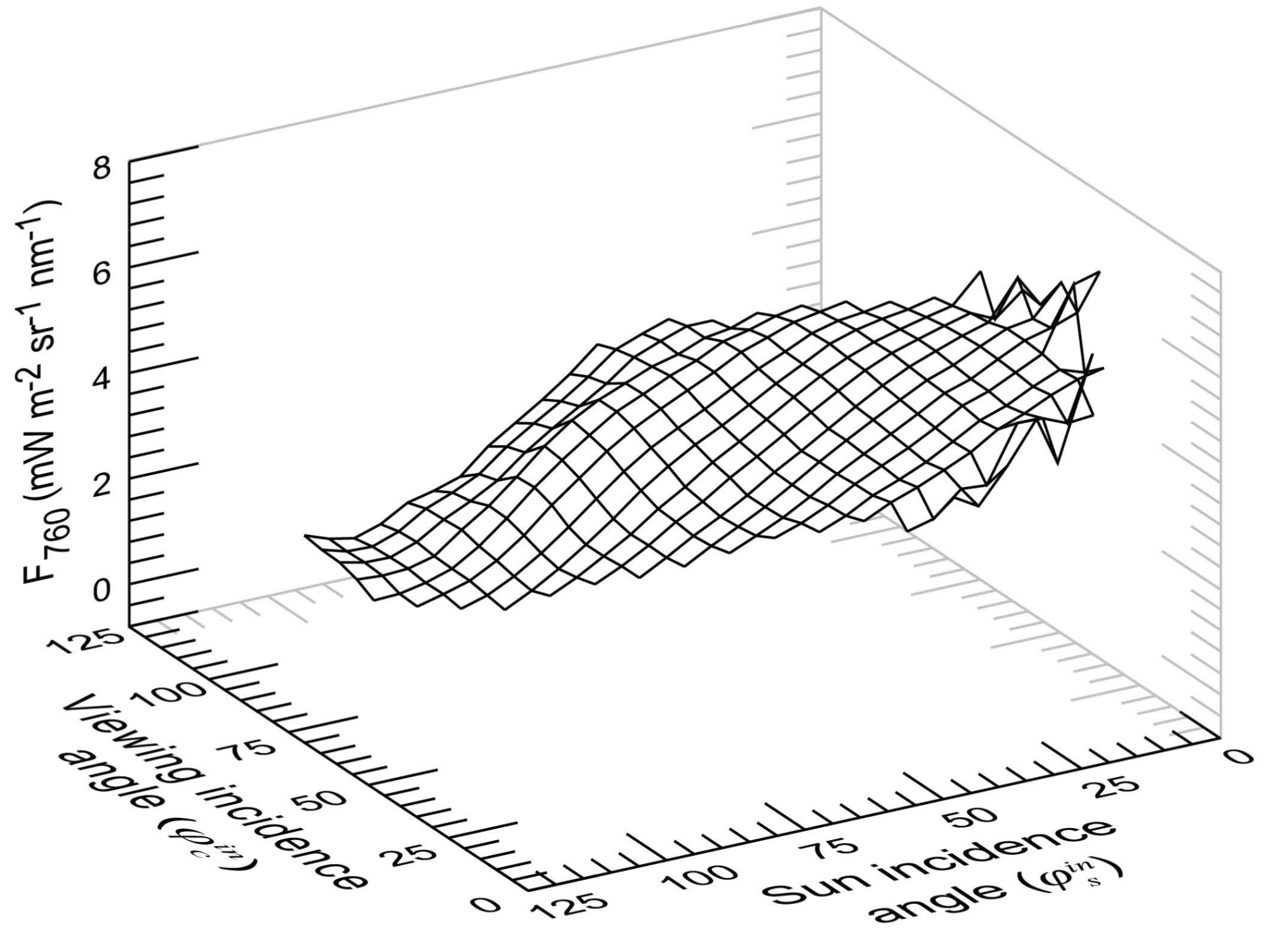
The variability observed among surfaces with a particular φ s i n in Figure 7a can be partly attributed to an effect of the viewing angle of the camera relative to the leaf surface. Figure 8 shows how F760 varied as a function of φ s i n and φ c i n during the midday measurement. In general, F760 tended to increase with higher viewing angles. However, an interdependency between φ c i n and φ s i n was observed. The increase of the viewing angle resulted in larger changes of F760 when φ s i n was between 35° and 100°. It is worth noting that the values in Figure 8 represent the F760 integrated over all azimuth angles at given φ s i n and φ c i n . This is because the narrow FOV of our hyperspectral camera and the static nature of the measurements limited the range of possible angle combinations for each scene. Consequently, it was not possible to analyze the changes of F760 as a function of the relative azimuth between the viewing and illumination incident vectors.

3.4. Diurnal Variations of Canopy F760

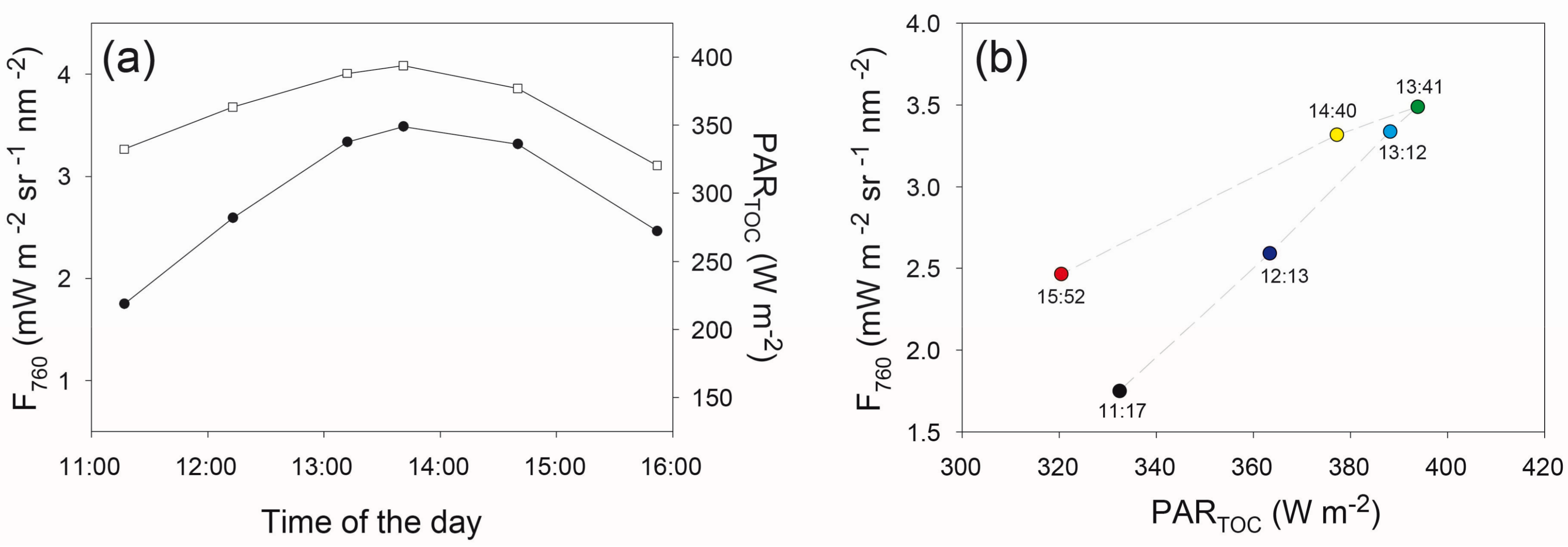
Diurnal variations of canopy F760 closely followed the changes of incoming PARTOC (Figure 9a). However, the rate of change of F760, and therefore its relationship with PARTOC, was different between the morning and the afternoon. In the morning, when light intensity increased, the relationship followed a different trajectory than in the afternoon under decreasing light intensities (Figure 9b). Starting from a median value of 1.75 mW m−2 sr−1 nm−1, F760 increased by two folds from morning to noon, where a peak of approximately 3.5 mW m−2 sr−1 nm−1 was detected. In the afternoon, F760 dropped down to 2.5 mW m−2 sr−1 nm−1, following the decrease of PARTOC. A similar trend, but with higher values of F760, was observed when using the mean of only pixels from class 1 (Figure S1). This suggests that the same factors could be affecting the temporal changes of this group of pixels and the integrated measurements over the whole canopy.

3.5. Effect of the Leaf Orientations on Diurnal Variations of F760//

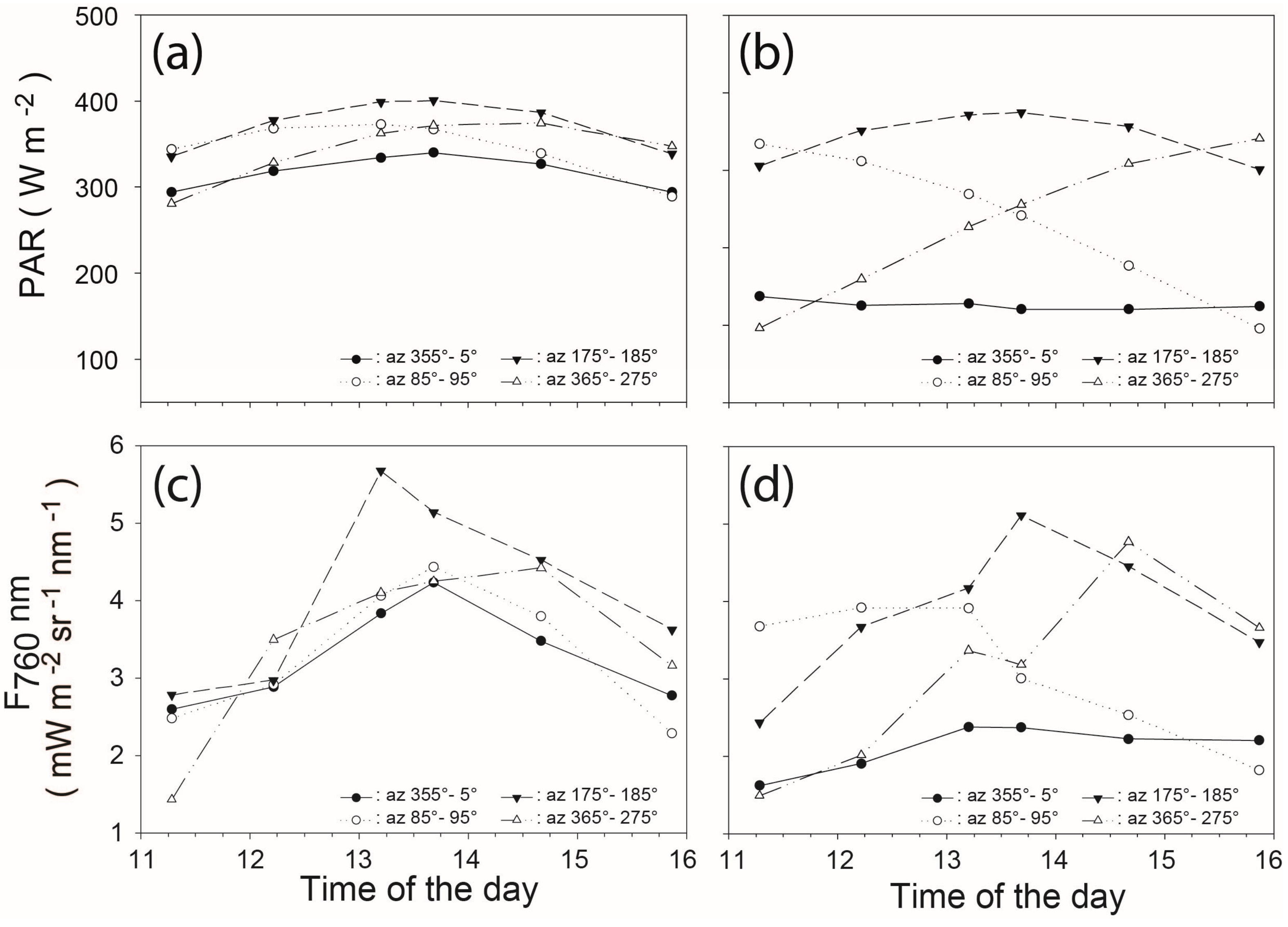
In order to evaluate the impact of leaf orientation in the diurnal patterns of canopy fluorescence, we analyzed the diurnal changes of F760 for different groups of pixels from class 1 classified according to their φ l and θ l . Figure 10c,d shows the diurnal course of F760 for flat ( φ l from 10° to 20°) and erected ( φ l from 60° to 70°) surfaces, respectively. For each group, surfaces oriented to the four cardinal points were evaluated separately (Figure 10). The incident PAR was simulated for each surface group and is shown in Figure 10a,b. F760 in flat surfaces facing to the north and east gradually increased from the morning and reached a peak at noon (Figure 10c, closed and open circles). Higher values of F760 were observed at noon in flat surfaces pointing to the south (Figure 10c, closed triangles). The peak of F760 in south and north facing surfaces coincided with the maximum incident PAR (Figure 10a, closed circles and triangles). That was not the case in east oriented flat surfaces, where the maximum PAR was estimated for the morning hours (Figure 10a, open circles). West oriented surfaces showed increasing values of F760 towards the afternoon (Figure 10c, open triangles) following the PAR pattern (Figure 10a, open triangles). In erected surfaces, diurnal variations of F760 and PAR were larger than in flat surfaces (Figure 10d). East facing surfaces reached their peak quickly in the morning and later decayed, coinciding with a strong reduction of the incident radiation (Figure 10b,d open circles). The inverse occurred in surfaces facing to the west (Figure 10b,d open triangles). The highest F760 was again observed at noon in south facing surfaces (Figure 10d, closed triangles), where the incident PAR was the highest (Figure 10b, closed triangles). Finally, a less pronounced diurnal course of F760 was observed in surfaces pointing north (Figure 10d closed circles), where the simulated incident radiation was low during the whole day (Figure 10b, closed circles).
Figure 11 provides a more complete view of the spatial distribution of F760 as a function of φ l and θ l at each time of the day. Diurnal variations of the F760 intensity and its spatial distribution were related to changes in light intensity and the sun position. For each scene, the highest F760 values were mostly measured in surfaces with a θ l close to θ s . This produced a clock-wise rotation of the F760 pattern from the morning to the afternoon following the movement of the sun from southeast to southwest. On the other hand, high values of F760 were observed at each time of the day in surfaces nearly perpendicular to the sun rays (i.e., φ s i n 0 ). Interestingly, the effect of larger φ s i n on the level of F760 varied depending on the inclination of the surfaces. In the solar principal plane (i.e., θ l θ s ), flatter surfaces showed a decrease of F760 with an increase of φ s i n (i.e., lower φ l ,). Conversely, the increase of φ s i n in erected surfaces (i.e., higher φ l ) resulted in higher F760 values (e.g., Figure 11, 12:13 p.m.).

4. Discussion

The importance of considering the effect of the canopy structure and the sun-canopy-sensor geometry in the retrieval and interpretation of the canopy sun-induced fluorescence has been stressed previously [13,15,24,25,30,33,35]. This study represents the first study to experimentally quantify this effect using an accurate parameterization of the canopy architecture in combination with highly detailed maps of canopy fluorescence estimated from field data. The novel technique introduced in this work allowed evaluating the link between the spatio-temporal variations of fluorescence emission at 760 nm and the leaf surface angles. In the following, we first discuss the performance of our approach, indicating the advantages and possible sources of error. Subsequently, we discuss the implications of our results in the interpretation of F760 at canopy level.

4.1. Performance of the Imaging Systems and the Image to Image Registration Algorithm

The two imaging systems used in this study provide a good trade-off between a good spatial resolution, adequate performance in the field and a reasonable price. Their sizes and portability contribute to the versatility of the measuring platform, which is enhanced by the flexibility of the cherry picker to reach different zones of the canopy. Additionally, the capability to adjust the orientation of the cameras and their distance to the vegetation permits to regulate the spatial resolution of the image, the time needed for the data acquisition and the homogeneity of the area to be measured.
Our approach takes advantage of the spatially resolved information given by the imaging spectroscopy and the stereo imaging data to derive the multi-angular variation of canopy radiance and F760. While in other approaches that use goniometers the sensor is moved around the target to create different sun-canopy-sensor geometries, our methodology achieve this in a single measurement combining the leaf angles with the different viewing angles of the pixels. This provides great flexibility and fast data acquisition. However, it also implies that both images must be accurately aligned. Such alignment is difficult to accomplish in real time given the differences in field of view, the nature of the data and recording time of the two cameras. Therefore, we suggest an approach that aligns both images during the post-processing based in features recognition. This permits the use of non-calibrated setups during the data acquisition, but, at the same time, it demands the detection of many key points for accuracy. The rough surface of the sugar beet leaves ensures the presence of many identifiable features in both images. However, this can also be a potential drawback when using high resolution imaging. A larger amount of spatial features increased the probability of errors in the alignment between RGBspec and RGBstereo, and thus biased the analysis.
Some of the factors that can affect the accuracy of the image to image registration include: the differences in acquisition time, data acquisition mode (i.e., linear scanning vs. snapshot) and the different optical paths of the two imaging systems. For instance, the longer recording time needed by the hyperspectral camera compared to the stereo camera setup resulted in some shape distortions caused by wind, which hampered the alignment in some areas. On the other hand, the two acquisition modes produced differences in viewing perspective. The best correspondence occurred when the imaging spectroscopy setup was scanning right over the stereo rig, which also minimized the occluded regions in the stereo images. Moreover, differences in perspective can derive in discrepancies of the coordinates for the same point in both images, especially in those surfaces which are at a different height than the field markers. Other sources of uncertainties can also bias the analysis of the data, such as the intrinsic noise of each sensor and the methodological constraints for the retrieval of their respective products.
The implementation of a block matching approach and the final selection of corresponding pixels based in their correlation proved to be a robust approach and the visual inspection and sensitivity test demonstrated that the algorithm produces coherent maps despite the variability within the experimental data. A clear relationship exists between the radiance at illuminated leaves and the inclination angles of their surfaces. As shown in Figure 4, this relationship is close to the model proposed in Equation (7). Additionally, the quick reduction of this relationship as a result of spatial shifts indicates a high sensitivity of the approach to subtle inaccuracies. Nevertheless, the results from the sensitivity analysis provide enough evidences that the output of our image to image registration is accurate enough for further analysis.

4.2. Challenges in Fluorescence Retrievals from High Spatial Resolution Imaging Spectroscopy Data

Some considerations must be taken into account when measuring canopy sun-induced fluorescence using high resolution imagery. Sources of uncertainties related to the sensor characteristics and the complex radiative transfer in the canopy can bias the interpretation of the results.
It has been reported that the sensor characteristics have an impact on the accuracy of fluorescence calculations [25,46,53,54]. Based on the simulations made by Damm et al. [46] our sensor meets the minimum requirements that enable reliable estimations of F760 in the O2-A band using the FLD principle (FWHM is <5 nm and SNR is >100). In fact, the same sensor was successfully used in a previous study to describe spatio-temporal distribution of F760 related to changes of photosynthetic activity [15].
Further uncertainties can result from the assumption of homogenous surface irradiance and of a Lambertian’ s surface reflectance [24]. This is critical at higher spatial resolutions, where the heterogeneity in the illumination conditions becomes more evident. Further, this heterogeneity results in differences between the fraction of diffuse and direct components of the solar irradiance which, together with the anisotropy of the surface, can cause spectral fluctuations of the surface reflectance around the O2-A band that may lead to large uncertainties in the calculation of F760 [24,33]. Although the information about the illumination geometry is provided in our data, more accurate estimations of the surface irradiance rely on improved characterizations of the atmosphere and the canopy radiative transfer. On the other hand, it is not possible to perform a full characterization of the surface anisotropy (BRDF) with the current dataset (see Figure 8). This can be potentially achieved by increasing the range of illumination and viewing angles. Nevertheless, the implementation of these improvements is beyond the scope of this study.
Despite the constraints mentioned above, the retrieval algorithm resulted in consistent maps of fluorescence at 760 nm (for example see Figure 3d) where integrated values over the vegetation were within the range of those reported in the literature (for review, see [13]).

4.3. Spatio-Temporal Variations of F760 as a Function of the Leaf Orientations and the Viewing Geometry

All our results indicate a close relationship between the level of PAR and the retrieved F760 at canopy as well as for leaf surface level (Figure 7, Figure 9 and Figure 10). Previous studies have acknowledged APAR as the main factor driving the emission of sun-induced fluorescence, especially under non-stressing conditions [16,17,29,55]. At the leaf level, we observed that the spatial variations of fluorescence emission were related to the relative angle between the surface and the solar radiation, which in turn determined the amount of PAR incident on a leaf surface. Interestingly, the variation of the F760 values demonstrated to be less dependent on φ s i n than the level of reflected radiances. While the sun incidence angle explained nearly 70% of the variability of the reflected radiance in sunlit surfaces, it only explained about 40% of the F760 variability (Figure 7). The non-linear relationship between PAR and F760 observed in some of the surfaces analyzed in the Figure 10 suggests that the level of fluorescence was not only driven by the incoming radiation. It has been reported that the linear relationship between PAR and F760 may become affected by additional factors such as local differences in leaf pigment composition and functional status of photosynthesis [6,56,57,58]. Major deviations can occur during the course of the day when non-photochemical mechanisms for energy dissipation are activated under high light conditions.
The view geometry also contributed to the variability of F760 measured at the leaf surface level. Higher viewing angles resulted in an increase of F760. Something similar was observed at canopy level by van der Tol et al. [34], who reported that increasing the viewing zenith angles increased the fraction of the sunlit vegetation that is visible to the sensor. Similarly, in a rough surface such as a sugar beet leaf, higher viewing angles increase the probability of observing a larger fraction of sunlit facets, which contribute most to the F760. Furthermore, it has been reported that this effect is accentuated at oblique solar incident angles [59,60,61].
At canopy level, we observed diurnal variations of the rate of change of F760 with respect to PAR. Our observations support the idea that this is partly determined by the proportion of leaf surfaces facing towards the sun at a specific time of the day (and the fraction of leaf surfaces under diffuse radiation). In this particular case, the studied canopy had a larger proportion of leaf surfaces pointing towards the east (Figure 6b) which could yield in higher canopy F760 in afternoon hours compared to the morning. Nevertheless, the effect of changes in the functional status of photosynthesis on the diurnal pattern of F760 at canopy level cannot be discarded. Although we did not measure photosynthesis directly, the relationship between diurnal changes in photochemistry and fluorescence has been previously reported. The fast increase of PAR in the morning activates the photosynthesis and reduces the quantum yield of photochemistry, resulting in a fast increase of fluorescence [6,62,63]. The activation of photoprotection mechanisms towards noon changes the relationship of PAR and fluorescence emission [6,58,64].

5. Conclusions

The novel approach presented in this study permitted for the first time a direct evaluation of the effect that canopy structure has in the spatio-temporal patterns of sun-induced fluorescence emission. We identified two major components that define the diurnal changes of spatial patterns of fluorescence measured on top-of-the-canopy: (i) the spatial disposition of leaves which determine the penetration of light and its distribution as a complex and fluctuating mosaic within the canopy; and (ii) the fluorescence emission at individual leaf surfaces which is modulated by the surface orientation and the functional status of the photosynthesis in that area. The architecture of the sugar beet canopy used in this study was rather simple and with large leaves that ensured a high proportion of leaf surfaces exposed to direct radiation. The relative orientation of the leaf surfaces with respect to the sun determined a wide range of sun incidence angles at a given time, causing variations in the illumination conditions. This effect was enhanced by the roughness of the sugar beet leaves. During the day, the dynamic changes in the illumination geometries contributed to the spatio-temporal variations of F760. This reveals the impact that the surface angle distribution has on the levels of F760 and remarks the importance of considering the canopy structure for the proper interpretation of the signal. Separating the structural from the functional effect in the fluorescence emission is challenging and we believe this work represent a first step in this direction.
The results of this study show the potential of integrated measurements of hyperspectral and stereo imaging data for studying the directional distribution of fluorescence emission within the canopy and validating the existing radiative transfer models. Our sensitivity test demonstrated the consistency of our approach despite some limitations regarding to the sensors characteristics and acquisition conditions. On the other hand, we observed variations of F760 related to the viewing incidence angle of the sensor. We attribute them to the reflectance anisotropy of the rough vegetation surface which can affect the retrieval of F760. However, the static nature of a single measurement reduced the number of possible angle combinations, not allowing a full analysis on the effect of the surface BRDF on F760. Given the flexibility of the setup, this problem can be solved by adding few extra measurements at different camera orientations. This approach is a simple but useful tool with a great potential to understand the effect of the plant architecture on sun-induced fluorescence measured TOC.

Supplementary Materials

The following are available online at www.mdpi.com/2072-4292/9/5/415/s1, Figure S1: Diurnal changes of canopy sun-induced chlorophyll fluorescence measured at 760 nm (F760) in sugar beet. Each data point representsthe median F760 at each measuring time for: all vegetation pixels including sunlit and shaded surfaces (closed squares), vegetation pixels classified as class 1 (closed circles), vegetation pixels classified as class 2 (open circles). The data was collected over a single day.

Acknowledgments

This work was supported by the scholarship program of CONICYT–DAAD and by the research program number 315309/CROP.SENSe.net funded by BMBF. The authors are grateful to: Kai Schmidt, Manfred Trimborn, Heiner Goldbach, Jens Leon and other members of the Agricultural Faculty of Bonn University who have enabled the measurements by providing the sugar beet experiments at Campus Klein-Altendorf.

Author Contributions

F.P., M.M.-L. and U.R. conceived the experiments; F.P. and M.M.-L. designed and performed the experiments; F.P. and M.M.-L. analyzed the data; A.S., M.P.C.-M., A.B. and U.R. participated in the interpretation of data patterns and study results and edited the paper; and F.P. wrote the paper.

Conflicts of Interest

The authors declare no conflict of interest.

References

  1. Meroni, M.; Colombo, R. Leaf level detection of solar induced chlorophyll fluorescence by means of a subnanometer resolution spectroradiometer. Remote Sens. Environ. 2006, 103, 438–448. [Google Scholar] [CrossRef]
  2. Meroni, M.; Rossini, M.; Picchi, V.; Panigada, C.; Cogliati, S.; Nali, C.; Colombo, R. Assessing steady-state fluorescence and PRI from hyperspectral proximal sensing as early indicators of plant stress: The case of ozone exposure. Sensors 2008, 8, 1740–1754. [Google Scholar] [CrossRef] [PubMed]
  3. Rossini, M.; Meroni, M.; Migliavacca, M.; Manca, G.; Cogliati, S.; Busetto, L.; Picchi, V.; Cescatti, A.; Seufert, G.; Colombo, R. High resolution field spectroscopy measurements for estimating gross ecosystem production in a rice field. Agric. For. Meteorol. 2010, 150, 1283–1296. [Google Scholar] [CrossRef]
  4. Zarco-Tejada, P.J.; Morales, A.; Testi, L.; Villalobos, F.J. Spatio-temporal patterns of chlorophyll fluorescence and physiological and structural indices acquired from hyperspectral imagery as compared with carbon fluxes measured with eddy covariance. Remote Sens. Environ. 2013, 133, 102–115. [Google Scholar] [CrossRef]
  5. Krause, G.H.; Weis, E. Chlorophyll fluorescence and photosynthesis—The basics. Annu. Rev. Plant Phys. 1991, 42, 313–349. [Google Scholar] [CrossRef]
  6. Van der Tol, C.; Verhoef, W.; Rosema, A. A model for chlorophyll fluorescence and photosynthesis at leaf scale. Agric. For. Meteorol. 2009, 149, 96–105. [Google Scholar] [CrossRef]
  7. Buschmann, C. Variability and application of the chlorophyll fluorescence emission ratio red/far-red of leaves. Photosynth. Res. 2007, 92, 261–271. [Google Scholar] [CrossRef] [PubMed]
  8. Lichtenthaler, H.K.; Rinderle, U. The role of chlorophyll fluorescence in the detection of stress conditions in plants. CRC Crit. Rev. Anal. Chem. 1988, 19, S29–S85. [Google Scholar] [CrossRef]
  9. Franck, F.; Juneau, P.; Popovic, R. Resolution of the photosystem I and photosystem II contributions to chlorophyll fluorescence of intact leaves at room temperature. Biochim. Biophys. Acta Bioenerg. 2002, 1556, 239–246. [Google Scholar] [CrossRef]
  10. Plascyk, J.A. MK II Fraunhofer line discriminator (FLD-II) for airborne and orbital remote-sensing of solar-stimulated luminescence. Opt. Eng. 1975, 14, 339–346. [Google Scholar] [CrossRef]
  11. Maier, S.W.; Günther, K.P.; Stellmes, M. Sun-induced fluorescence: A new tool for precision farming. In Digital Imaging and Spectral Techniques: Applications to Precision Agriculture and Crop Physiology; ASA Special Publication 66; VanToai, T., Ed.; American Society of Agronomy, Crop Science Society of America, Soil Science Society of America Madison: Madison, WI, USA, 2003; pp. 209–222. [Google Scholar]
  12. Moya, I.; Camenen, L.; Evain, S.; Goulas, Y.; Cerovic, Z.G.; Latouche, G.; Flexas, J.; Ounis, A. A new instrument for passive remote sensing 1. Measurements of sunlight-induced chlorophyll fluorescence. Remote Sens. Environ. 2004, 91, 186–197. [Google Scholar] [CrossRef]
  13. Meroni, M.; Rossini, M.; Guanter, L.; Alonso, L.; Rascher, U.; Colombo, R.; Moreno, J. Remote sensing of solar-induced chlorophyll fluorescence: Review of methods and applications. Remote Sens. Environ. 2009, 113, 2037–2051. [Google Scholar] [CrossRef]
  14. Alonso, L.; Gomez-Chova, L.; Vila-Frances, J.; Amoros-Lopez, J.; Guanter, L.; Calpe, J.; Moreno, J. Improved fraunhofer line discrimination method for vegetation fluorescence quantification. IEEE Geosci. Remote Sens. Lett. 2008, 5, 620–624. [Google Scholar] [CrossRef]
  15. Pinto, F.; Damm, A.; Schickling, A.; Panigada, C.; Cogliati, S.; Müller-Linow, M.; Balvora, A.; Rascher, U. Sun-induced chlorophyll fluorescence from high-resolution imaging spectroscopy data to quantify spatio-temporal patterns of photosynthetic function in crop canopies. Plant Cell Environ. 2016, 39, 1500. [Google Scholar] [CrossRef] [PubMed]
  16. Cogliati, S.; Rossini, M.; Julitta, T.; Meroni, M.; Schickling, A.; Burkart, A.; Pinto, F.; Rascher, U.; Colombo, R. Continuous and long-term measurements of reflectance and sun-induced chlorophyll fluorescence by using novel automated field spectroscopy systems. Remote Sens. Environ. 2015, 164, 270–281. [Google Scholar] [CrossRef]
  17. Daumard, F.; Goulas, Y.; Champagne, S.; Fournier, A.; Ounis, A.; Olioso, A.; Moya, I. Continuous monitoring of canopy level sun-induced chlorophyll fluorescence during the growth of a sorghum field. IEEE Trans. Geosci. Remote Sens. 2012, 50, 4292–4300. [Google Scholar] [CrossRef]
  18. Rascher, U.; Alonso, L.; Burkart, A.; Cilia, C.; Cogliati, S.; Colombo, R.; Damm, A.; Drusch, M.; Guanter, L.; Hanus, J.; et al. Sun-induced fluorescence—A new probe of photosynthesis: First maps from the imaging spectrometer hyplant. Glob. Chang. Biol. 2015, 21, 4673–4687. [Google Scholar] [CrossRef] [PubMed]
  19. Rossini, M.; Nedbal, L.; Guanter, L.; Ac, A.; Alonso, L.; Burkart, A.; Cogliati, S.; Colombo, R.; Damm, A.; Drusch, M.; et al. Red and far red sun-induced chlorophyll fluorescence as a measure of plant photosynthesis. Geophys. Res. Lett. 2015, 42, 1632–1639. [Google Scholar] [CrossRef]
  20. Simmer, C.; Thiele-Eich, I.; Masbou, M.; Amelung, W.; Bogena, H.; Crewell, S.; Diekkrüger, B.; Ewert, F.; Hendricks Franssen, H.-J.; Huisman, J.A. Monitoring and modeling the terrestrial system from pores to catchments: The transregional collaborative research center on patterns in the soil–vegetation–atmosphere system. Bull. Am. Meteorol. Soc. 2015, 96, 1765–1787. [Google Scholar] [CrossRef]
  21. Guanter, L.; Frankenberg, C.; Dudhia, A.; Lewis, P.E.; Gomez-Dans, J.; Kuze, A.; Suto, H.; Grainger, R.G. Retrieval and global assessment of terrestrial chlorophyll fluorescence from gosat space measurements. Remote Sens. Environ. 2012, 121, 236–251. [Google Scholar] [CrossRef]
  22. Guanter, L.; Zhang, Y.; Jung, M.; Joiner, J.; Voigt, M.; Berry, J.A.; Frankenberg, C.; Huete, A.R.; Zarco-Tejada, P.; Lee, J.-E.; et al. Global and time-resolved monitoring of crop photosynthesis with chlorophyll fluorescence. Proc. Natl. Acad. Sci. USA 2014, 111, E1327–E1333. [Google Scholar] [CrossRef] [PubMed]
  23. Joiner, J.; Guanter, L.; Lindstrot, R.; Voigt, M.; Vasilkov, A.P.; Middleton, E.M.; Huemmrich, K.F.; Yoshida, Y.; Frankenberg, C. Global monitoring of terrestrial chlorophyll fluorescence from moderate-spectral-resolution near-infrared satellite measurements: Methodology, simulations, and application to gome-2. Atmos. Meas. Tech. 2013, 6, 2803–2823. [Google Scholar] [CrossRef]
  24. Damm, A.; Guanter, L.; Verhoef, W.; Schläpfer, D.; Garbari, S.; Schaepman, M.E. Impact of varying irradiance on vegetation indices and chlorophyll fluorescence derived from spectroscopy data. Remote Sens. Environ. 2015, 156, 202–215. [Google Scholar] [CrossRef]
  25. Guanter, L.; Alonso, L.; Gomez-Chova, L.; Meroni, M.; Preusker, R.; Fischer, J.; Moreno, J. Developments for vegetation fluorescence retrieval from spaceborne high-resolution spectrometry in the O2-A and O2-B absorption bands. J. Geophys. Res. Atmos. 2010, 115, 1485–1490. [Google Scholar] [CrossRef]
  26. Kobayashi, H.; Iwabuchi, H. A coupled 1-D atmosphere and 3-D canopy radiative transfer model for canopy reflectance, light environment, and photosynthesis simulation in a heterogeneous landscape. Remote Sens. Environ. 2008, 112, 173–185. [Google Scholar] [CrossRef]
  27. Govind, A.; Guyon, D.; Roujean, J.-L.; Yauschew-Raguenes, N.; Kumari, J.; Pisek, J.; Wigneron, J.-P. Effects of canopy architectural parameterizations on the modeling of radiative transfer mechanism. Ecol. Model. 2013, 251, 114–126. [Google Scholar] [CrossRef]
  28. Rascher, U.; Nedbal, L. Dynamics of photosynthesis in fluctuating light. Curr. Opin. Plant Biol. 2006, 9, 671–678. [Google Scholar] [CrossRef] [PubMed]
  29. Malenovský, Z.; Mishra, K.B.; Zemek, F.; Rascher, U.; Nedbal, L. Scientific and technical challenges in remote sensing of plant canopy reflectance and fluorescence. J. Exp. Bot. 2009, 60, 2987–3004. [Google Scholar] [CrossRef] [PubMed]
  30. Fournier, A.; Daumard, F.; Champagne, S.; Ounis, A.; Goulas, Y.; Moya, I. Effect of canopy structure on sun-induced chlorophyll fluorescence. ISPRS J. Photogramm. Remote Sens. 2012, 68, 112–120. [Google Scholar] [CrossRef]
  31. Van Wittenberghe, S.; Alonso, L.; Verrelst, J.; Moreno, J.; Samson, R. Bidirectional sun-induced chlorophyll fluorescence emission is influenced by leaf structure and light scattering properties—A bottom-up approach. Remote Sens. Environ. 2015, 158, 169–179. [Google Scholar] [CrossRef]
  32. Gitelson, A.A.; Buschmann, C.; Lichtenthaler, H.K. Leaf chlorophyll fluorescence corrected for re-absorption by means of absorption and reflectance measurements. J. Plant Phys. 1998, 152, 283–296. [Google Scholar] [CrossRef]
  33. Miller, J.R.; Berger, M.; Goulas, Y.; Jacquemoud, S.; Louis, J.; Moise, N.; Mohammed, G.; Moreno, J.; Moya, I.; Pedrós, R.; et al. Development of a Vegetation Fluorescence Canopy Model; Final Report; European Space Research and Technology Centre (ESTEC): Noordwijk, The Netherlands, 2005. [Google Scholar]
  34. Van der Tol, C.; Verhoef, W.; Timmermans, J.; Verhoef, A.; Su, Z. An integrated model of soil-canopy spectral radiances, photosynthesis, fluorescence, temperature and energy balance. Biogeosciences 2009, 6, 3109–3129. [Google Scholar] [CrossRef]
  35. Zarco-Tejada, P.J.; Suarez, L.; Gonzalez-Dugo, V. Spatial resolution effects on chlorophyll fluorescence retrieval in a heterogeneous canopy using hyperspectral imagery and radiative transfer simulation. IEEE Geosci. Remote Sens. Lett. 2013, 10, 937–941. [Google Scholar] [CrossRef]
  36. Bellasio, C.; Olejníčková, J.; Tesař, R.; Šebela, D.; Nedbal, L. Computer reconstruction of plant growth and chlorophyll fluorescence emission in three spatial dimensions. Sensors 2012, 12, 1052–1071. [Google Scholar] [CrossRef] [PubMed]
  37. Biskup, B.; Küsters, R.; Scharr, H.; Walter, A.; Rascher, U. Quantification of plant surface structures from small baseline stereo images to measure the three-dimensional surface from the leaf to the canopy scale. Nova Acta Leopoldina 2009, 96, 31–47. [Google Scholar]
  38. Biskup, B.; Scharr, H.; Schurr, U.; Rascher, U. A stereo imaging system for measuring structural parameters of plant canopies. Plant Cell Environ. 2007, 30, 1299–1308. [Google Scholar] [CrossRef] [PubMed]
  39. Ehlert, D.; Heisig, M.; Adamek, R. Assessment of a laser scanner on agricultural machinery. In Proceedings of the Engineering for Rural Development-9th International Scientific Conference, Jelgava, Latvia, 27–28 May 2010; University of Agriculture: Jelgava, Latvia, 2010; pp. 32–36. [Google Scholar]
  40. Sanz-Cortiella, R.; Llorens-Calveras, J.; Arnó-Satorra, J.; Ribes-Dasi, M.; Masip-Vilalta, J.; Camp, F.; Gràcia-Aguilá, F.; Solanelles-Batlle, F.; Planas-DeMartí, S.; Pallejà-Cabré, T. Innovative Lidar 3d dynamic measurement system to estimate fruit-tree leaf area. Sensors 2011, 11, 5769–5791. [Google Scholar] [CrossRef] [PubMed]
  41. Müller-Linow, M.; Pinto, F.; Scharr, H.; Rascher, U. The leaf angle distribution of natural plant populations: Assessing the canopy with a novel software tool. Plant Methods 2015, 11. [Google Scholar] [CrossRef] [PubMed]
  42. Hack, H.; Bleiholder, H.; Buhr, L.; Meier, U.; Schnock-Fricke, U.; Weber, E.; Witzenberger, A. Einheitliche codierung der phänologischen entwicklungsstadien mono-und dikotyler pflanzen–erweiterte BBCH-Skala, Allgemein. Nachrichtenblatt Deutschen Pflanzenschutzd. 1992, 44, 265–270. [Google Scholar]
  43. Kimes, D.; Kirchner, J. Irradiance measurement errors due to the assumption of a lambertian reference panel. Remote Sens. Environ. 1982, 12, 141–149. [Google Scholar] [CrossRef]
  44. Doxaran, D.; Cherukuru, N.C.; Lavender, S.J.; Moore, G.F. Use of a spectralon panel to measure the downwelling irradiance signal: Case studies and recommendations. Appl. Opt. 2004, 43, 5981–5986. [Google Scholar] [CrossRef] [PubMed]
  45. Liu, L.Y.; Zhang, Y.J.; Wang, J.H.; Zhao, C.J. Detecting solar-induced chlorophyll fluorescence from field radiance spectra based on the fraunhofer line principle. IEEE Trans. Geosci. Remote Sens. 2005, 43, 827–832. [Google Scholar]
  46. Damm, A.; Erler, A.; Hillen, W.; Meroni, M.; Schaepman, M.E.; Verhoef, W.; Rascher, U. Modeling the impact of spectral sensor configurations on the FLD retrieval accuracy of sun-induced chlorophyll fluorescence. Remote Sens. Environ. 2011, 115, 1882–1892. [Google Scholar] [CrossRef]
  47. Guanter, L.; Richter, R.; Kaufmann, H. On the application of the modtran4 atmospheric radiative transfer code to optical remote sensing. Int. J. Remote Sens. 2009, 30, 1407–1424. [Google Scholar] [CrossRef]
  48. Meroni, M.; Busetto, L.; Guanter, L.; Cogliati, S.; Crosta, G.F.; Migliavacca, M.; Panigada, C.; Rossini, M.; Colombo, R. Characterization of fine resolution field spectrometers using solar fraunhofer lines and atmospheric absorption features. Appl. Opt. 2010, 49, 2858–2871. [Google Scholar] [CrossRef] [PubMed]
  49. Guanter, L. New Algorithms for Atmospheric Correction and Retrieval of Biophysical Parameters in Earth Observation. Application to Envisat/Meris Data; Department de Fisica de la Terra i Termodinàmica, Universitat de València: Valencia, Spain, 2007; p. 266. [Google Scholar]
  50. Damm, A.; Guanter, L.; Laurent, V.C.E.; Schaepman, M.E.; Schickling, A.; Rascher, U. Fld-based retrieval of sun-induced chlorophyll fluorescence from medium spectral resolution airborne spectroscopy data. Remote Sens. Environ. 2014, 147, 256–266. [Google Scholar] [CrossRef]
  51. Lowe, D.G. Distinctive image features from scale-invariant keypoints. Int. J. Comput. Vis. 2004, 60, 91–110. [Google Scholar] [CrossRef]
  52. Brown, M.Z.; Burschka, D.; Hager, G.D. Advances in computational stereo. IEEE Trans. Pattern Anal. Mach. Intell. 2003, 25, 993–1008. [Google Scholar] [CrossRef]
  53. Corp, L.A.; Middleton, E.M.; Cheng, Y.B.; Campbell, P.; Huemmrich, K.F. Impact of spectral resolution on solar induced fluorescence and reflectance indices for monitoring vegetation. In Proceedings of the IEEE International Geoscience and Remote Sensing Symposium, Boston, MA, USA, 7–11 July 2008; pp. IV-1387–IV-1390. [Google Scholar]
  54. Middleton, E.M.; Corp, L.A.; Campbell, P.K.E. Comparison of measurements and fluormod simulations for solar-induced chlorophyll fluorescence and reflectance of a corn crop under nitrogen treatments. Int. J. Remote Sens. 2008, 29, 5193–5213. [Google Scholar] [CrossRef]
  55. Flexas, J.; Briantais, J.M.; Cerovic, Z.; Medrano, H.; Moya, I. Steady-state and maximum chlorophyll fluorescence responses to water stress in grapevine leaves: A new remote sensing system. Remote Sens. Environ. 2000, 73, 283–297. [Google Scholar] [CrossRef]
  56. Flexas, J.; Escalona, J.M.; Evain, S.; Gulias, J.; Moya, I.; Osmond, C.B.; Medrano, H. Steady-state chlorophyll fluorescence (FS) measurements as a tool to follow variations of net CO2 assimilation and stomatal conductance during water-stress in C3 plants. Physiol. Plant. 2002, 114, 231–240. [Google Scholar] [CrossRef] [PubMed]
  57. Müller, P.; Li, X.-P.; Niyogi, K.K. Non-photochemical quenching. A response to excess light energy. Plant Physiol. 2001, 125, 1558–1566. [Google Scholar] [CrossRef] [PubMed]
  58. Amoros-Lopez, J.; Gomez-Chova, L.; Vila-Frances, J.; Alonso, L.; Calpe, J.; Moreno, J.; del Valle-Tascon, S. Evaluation of remote sensing of vegetation fluorescence by the analysis of diurnal cycles. Int. J. Remote Sens. 2008, 29, 5423–5436. [Google Scholar] [CrossRef]
  59. Bousquet, L.; Lachérade, S.; Jacquemoud, S.; Moya, I. Leaf BRDF measurements and model for specular and diffuse components differentiation. Remote Sens. Environ. 2005, 98, 201–211. [Google Scholar] [CrossRef]
  60. Torrance, K.E.; Sparrow, E.M. Theory for off-specular reflection from roughened surfaces. J. Opt. Soc. Am. 1967, 57, 1105–1114. [Google Scholar] [CrossRef]
  61. Walter-Shea, E.; Norman, J.; Blad, B. Leaf bidirectional reflectance and transmittance in corn and soybean. Remote Sens. Environ. 1989, 29, 161–174. [Google Scholar] [CrossRef]
  62. Schickling, A.; Matveeva, M.; Damm, A.; Schween, J.; Wahner, A.; Graf, A.; Crewell, S.; Rascher, U. Combining sun-induced chlorophyll fluorescence and photochemical reflectance index improves diurnal modeling of gross primary productivity. Remote Sens. 2016, 8, 574. [Google Scholar] [CrossRef]
  63. Damm, A.; Guanter, L.; Paul-Limoges, E.; Van der Tol, C.; Hueni, A.; Buchmann, N.; Eugster, W.; Ammann, C.; Schaepman, M. Far-red sun-induced chlorophyll fluorescence shows ecosystem-specific relationships to gross primary production: An assessment based on observational and modeling approaches. Remote Sens. Environ. 2015, 166, 91–105. [Google Scholar] [CrossRef]
  64. Amoros-Lopez, J.; Gomez-Chova, L.; Vila-Frances, J.; Calpe, J.; Alonso, L.; Moreno, J.; del Valle-Tascon, S. Study of the Diurnal Cycle of Stressed Vegetation for the Improvement of Fluorescence Remote Sensing. Proc. SPIE 2006. [Google Scholar] [CrossRef]
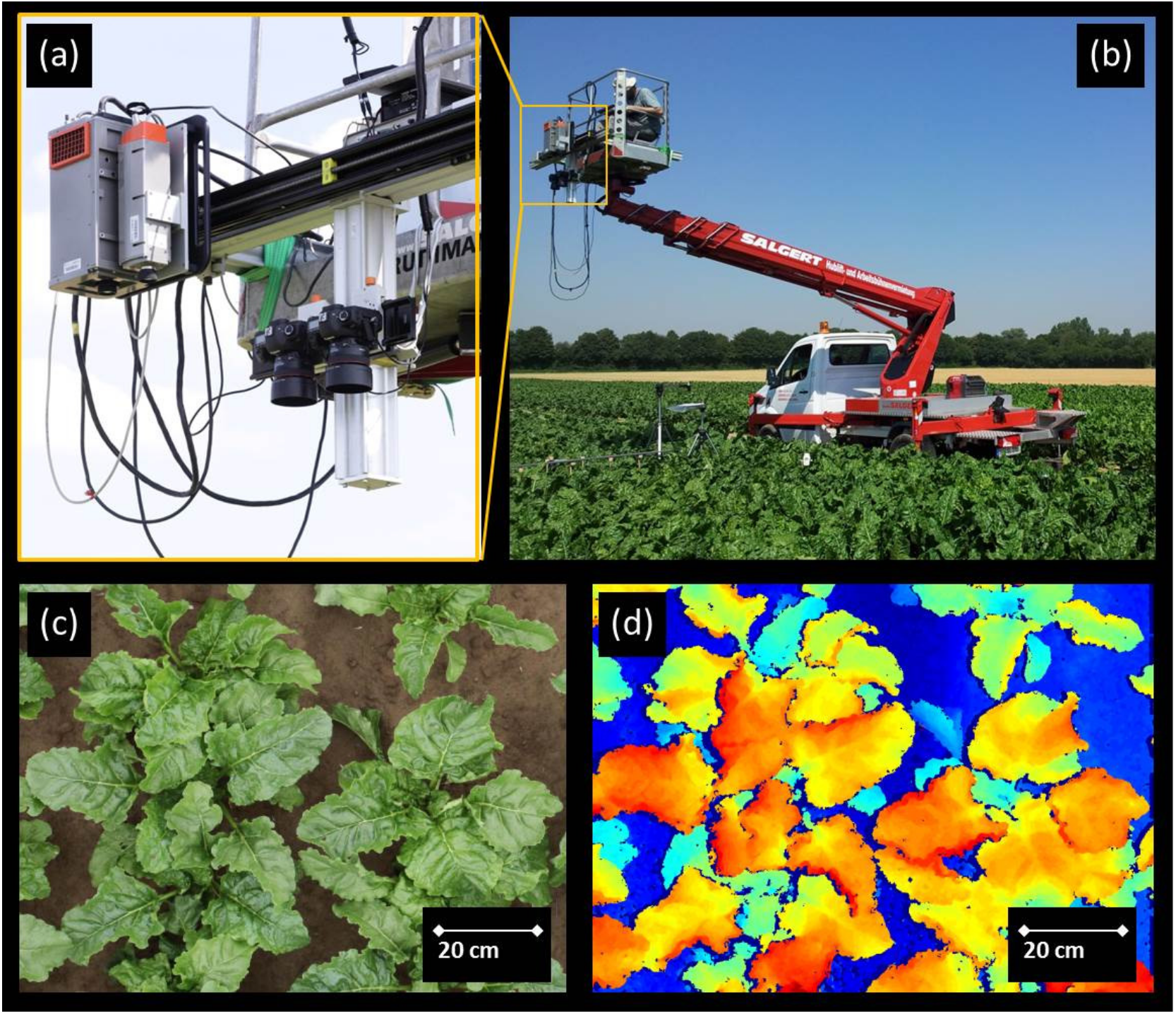
Figure 1. The measuring set up and the sugar beet (Beta vulgaris L. cv Pauletta) canopy used in the co-registration of imaging spectroscopy and stereo imaging data in the field. (a) The imaging spectroscopy system and the stereo camera setup were aligned for simultaneous data acquisition over a sugar beet canopy. (b) The measuring setup was mounted on a cherry picker for data acquisition 3.5 m top-of-canopy. (c) RGB (Red, Green, Blue) image of sugar beet plants used in this study acquired with one of the stereo cameras. (d) Disparity map of the sugar beet canopy obtained from the stereo imaging data and used for the leaf surface reconstruction. The color scale ranges from blue to red representing the largest and shortest distances between corresponding pixels, respectively.
Remotesensing 09 00415 g001
Figure 2. Processing scheme describing the steps for the image to image co-registration of sun-induced chlorophyll fluorescence at 760 nm (F760) and surface angles maps. Step I: Selection of RGB images from the imaging spectroscopy data (RGBspec) and the stereo imaging data (RGBstereo). Step II: Projective image transformation of RGBstereo using field markers (first rough alignment). Step III: Fine alignment using image key points (SIFT) and block matching. Step IV: Detection and masking out of non-matching pixels.
Remotesensing 09 00415 g002
Figure 3. Quality assessment of the canopy 3D reconstruction, sun-induced chlorophyll fluorescence measured at 760 nm (F760) and the image to image registration. (a) RGB image obtained from imaging spectroscopy data (RGBspec). (b) Example of aligned RGBspec and RGB″SCS images presented as a mosaic of interspersed tiles from both RGBs. It is worth noting that this is not how the data were actually used in the algorithm. (c) Leaf surface zenith ( φ l ) map. (d) Map of sun-induced chlorophyll fluorescence measured at 760 nm. Scale bar: 20 cm.
Remotesensing 09 00415 g003
Figure 4. Sensitivity test of the image to image registration. (a) 2D scatter plot between the sun incidence angle ( φ s i n ) and the vegetation surface radiance at 757 nm. Only pixels showing a correlation >0.15 between RGBspec and RGB″stereo were used. Three groups of surfaces can be distinguished: surfaces where the radiance varied as a function of φ s i n (red), shaded surfaces with no changes of radiance related to φ s i n (blue) and surfaces with discrepancies between their radiance and φ s i n (yellow). The curve in black represents the modeled surface radiance calculated using Equation (7) (see Section 2.8). (b,c) Changes in the relationship between φ s i n and vegetation surface radiance at 757 nm caused by spatial shifts in the angle maps of 5 and 40 pixels, respectively.
Remotesensing 09 00415 g004
Figure 5. Variation of the RMSE between observed and predicted values of reflected radiance as a function of the spatial shift applied during the sensitivity test. The predicted values were estimated using Equation (7) from Section 2.8.
Remotesensing 09 00415 g005
Figure 6. Leaf angle distribution of the sugar beet outer canopy. (a) Distribution of the zenith angles ( φ l ). The frequency is represented by the surface area measured for each angle. (b) 2D histogram for surface zenith ( φ l ) and azimuth ( θ l ) angles.
Remotesensing 09 00415 g006
Figure 7. Relationship between the sun incidence angle ( φ s i n ) and the level of sun-induced chlorophyll fluorescence measured at 760 nm (F760). (a) 2D scatter plot between the cosine of φ s i n and F760 in pixels representing leaf surfaces directly exposed to the sunlight. (b) 2D scatter plot between the cosine of φ s i n and F760 in pixels representing surfaces under shadow conditions. Only pixels showing a correlation >0.15 between RGBspec and RGB″stereo were used.
Remotesensing 09 00415 g007
Figure 8. Combined effect of the sun ( φ s i n ) and the viewing incidence angles ( φ c i n ) in the level of sun-induced chlorophyll fluorescence measured at 760 nm (F760).
Remotesensing 09 00415 g008
Figure 9. Diurnal changes of canopy sun-induced chlorophyll fluorescence measured at 760 nm (F760) in sugar beet. (a) Comparison between diurnal changes of F760 (closed circles) and PAR on top-of-canopy (PARTOC; opened squares). F760 values represent the median of all vegetation pixels (i.e., including sunlit and shaded surfaces) at each measuring time. PARTOC was estimated from the calibrated reflectance panel. (b) Changes in the relationship between PARTOC and F760 during the day. The data were collected over a single day.
Remotesensing 09 00415 g009
Figure 10. Diurnal changes of sun-induced chlorophyll fluorescence measured at 760 nm (F760) estimated for surfaces with different zenith ( φ l ) and azimuth ( θ l ) angles (being north θ l = 0° and east θ l = 90°). Simulated incident PAR for the surfaces with four different θ l and with a φ l : between 10° and 20° (a); and 60° and 70° (bd) show the diurnal variations of F760 for the surfaces represented in (a,b), respectively. Each point represents the F760 median of all surfaces within each group at each measuring time.
Remotesensing 09 00415 g010
Figure 11. Polar plots representing the distribution of sun-induced chlorophyll fluorescence measured at 760 nm (F760) as a function of the leaf surface zenith ( φ l ) and azimuth ( θ l ) at each measuring time. The sun position for each time of the day is represented by the small circle within each polar plot.
Remotesensing 09 00415 g011