Article

Surface Reflectance and Sun-Induced Fluorescence Spectroscopy Measurements Using a Small Hyperspectral UAS

Remote Sensing of Environmental Dynamics Laboratory. Department of Earth and Environmental Sciences, University of Milano-Bicocca, 20126 Milan, Italy
*
Author to whom correspondence should be addressed.
Remote Sens. 2017, 9(5), 472; https://doi.org/10.3390/rs9050472
Submission received: 25 January 2017 / Revised: 5 May 2017 / Accepted: 9 May 2017 / Published: 12 May 2017

Abstract

:
This study describes the development of a small hyperspectral Unmanned Aircraft System (HyUAS) for measuring Visible and Near-Infrared (VNIR) surface reflectance and sun-induced fluorescence, co-registered with high-resolution RGB imagery, to support field spectroscopy surveys and calibration and validation of remote sensing products. The system, namely HyUAS, is based on a multirotor platform equipped with a cost-effective payload composed of a VNIR non-imaging spectrometer and an RGB camera. The spectrometer is connected to a custom entrance optics receptor developed to tune the instrument field-of-view and to obtain systematic measurements of instrument dark-current. The geometric, radiometric and spectral characteristics of the instruments were characterized and calibrated through dedicated laboratory tests. The overall accuracy of HyUAS data was evaluated during a flight campaign in which surface reflectance was compared with ground-based reference measurements. HyUAS data were used to estimate spectral indices and far-red fluorescence for different land covers. RGB images were processed as a high-resolution 3D surface model using structure from motion algorithms. The spectral measurements were accurately geo-located and projected on the digital surface model. The overall results show that: (i) rigorous calibration enabled radiance and reflectance spectra from HyUAS with RRMSE < 10% compared with ground measurements; (ii) the low-flying UAS setup allows retrieving fluorescence in absolute units; (iii) the accurate geo-location of spectra on the digital surface model greatly improves the overall interpretation of reflectance and fluorescence data. In general, the HyUAS was demonstrated to be a reliable system for supporting high-resolution field spectroscopy surveys allowing one to collect systematic measurements at very detailed spatial resolution with a valuable potential for vegetation monitoring studies. Furthermore, it can be considered a useful tool for collecting spatially-distributed observations of reflectance and fluorescence that can be further used for calibration and validation activities of airborne and satellite optical images in the context of the upcoming FLEX mission and the VNIR spectral bands of optical Earth observation missions (i.e., Landsat, Sentinel-2 and Sentinel-3).

Graphical Abstract

1. Introduction

Field spectroscopy is an essential technique to gain valuable insights on Earth’s surface optical properties. These types of data are important for characterizing natural surfaces, supporting calibration and validation of airborne and satellite images and providing essential information for upscaling measurements from the local to the regional scale [1,2,3,4]. In general, the common way to collect field spectroscopy data relies on close-range measurements using portable non-imaging spectrometers [5,6]. Characterizing the spatial distribution of bio-geophysical parameters in heterogeneous areas could be challenging and time consuming, and errors could arise by moving the spectrometer from place to place. This limits the exploitation of field spectroscopy to a broader range of studies [7]. For example, the collection of top-of-canopy spectral measurements on high forest trees generally requires dedicated installations such as scaffolding towers or hydraulic platforms [8,9,10,11,12,13,14], limiting its applicability. Analogous complications can arise when field spectroscopy data must be collected in areas that are difficult to access, such as dense vegetation forest, mountain glaciers, volcanoes or in-land water bodies.
In the last decade, small Unmanned Aircraft Systems (UASs) are becoming widely-used tools for collecting data with a wide variety of sensors. The rapid growing of UASs is mainly motivated by the fact that they can provide rapid, flexible and cost-effective observations of the environment. Furthermore, UASs can facilitate a systematic sampling even for heterogeneous areas or areas that are difficult to access that can be integrated with traditional field spectroscopy surveys. Moreover, the flight maneuverability provided by UAS further motivates the deployment of scientific sensors on this type of system. In fact, platform flight parameters (e.g., altitude, speed, path, etc.) and payload characteristics (e.g., sensor sampling rate, viewing angle, etc.) can be easily tuned to fulfill specific observation requirements for different applications. For example, the spatial resolution can be modified by varying the flight altitude, enabling observation of either specific characteristics of individual targets rather than larger sampling areas in which details are averaged out. The combination of UAS with field spectroscopy constitutes a multi-scale approach that can be helpful for understanding the upscaling from in-field to airborne and satellite measurements, improving the analysis of large-scale environmental processes [15]. The capability of flying and recording data autonomously, according to a pre-defined plan, can improve the consistency of data collected in surveys repeated over time. Such a feature supports studies aimed at monitoring dynamic processes like crop yield or forest disease, which require frequent revisits during the entire growing season. It must be noted that UAS technology involves a wide range of platforms with very different technical characteristics suitable for different and specific applications. Usually, fixed-wing platforms are preferred to cover larger areas with an approach similar to airborne remote sensing. In comparison, rotary-wing systems usually fly at lower altitudes, allowing hovering over a target for a certain lapse of time to complete a series of specific measurements.
Evidence of the widespread exploitation of UASs is provided by the growing number of recent scientific studies covering a broad range of environmental applications [16,17]. Several investigations, for example, show how to derive a high-resolution 3D surface model and orthophoto by using Structure from Motion (SfM) algorithms on overlapped RGB images series [18,19,20,21,22]. Typical examples involve glaciers, snow and landslide monitoring [23,24,25,26,27,28,29,30,31]. The 3D models derived by UAS images have been also used to obtain information about plants’ canopy architecture, such as tree height and crown diameter [21,32,33,34]. Instead, other applications exploit more in detail the surface spectral response, such as studies related to snow radiative properties and water quality monitoring [35,36]. UAS-based multispectral and hyperspectral sensors have been also used for vegetation monitoring in agriculture applications. For example, plants’ biophysical and biochemical parameters can be derived from spectral information for evaluating plant stress caused by water or nitrogen deficiency [37,38,39,40]. From this point of view, UASs provide improved spatial and temporal resolutions for crop management [41,42,43,44].
Currently, the major limits of small UASs concern payload technical requirements (e.g., weight, size, power supply and data storage/downlink) and legislative regulations. The limited payload available on small UAS makes it difficult or prohibitive to deploy some high-performance scientific instruments. On the other hand, sensor miniaturization often entails lower data quality in terms of signal-to-noise ratio and spatial/spectral resolving power. For these reasons, applications that make use of small UAS are mostly based on RGB or VNIR multispectral cameras [41,45]. Conversely, the exploitation of hyperspectral imaging instruments is still limited because instrumentation and data processing techniques are more complex and technically expensive. However, a few pioneering works show the great potential of spectral data with high spatial and temporal resolution, for example in monitoring agricultural and natural vegetation [19,37,41,43,46,47]. In particular, Zarco-Tejada et al. (2012) [37] used a fixed-wing UAS and imaging spectrometer to collect reflectance signature, narrow-band Photochemical Reflectance Index (PRI) and Sun-Induced Fluorescence (SIF) to assess crop water stress. The capability of collecting high spatial resolution data from UASs, repeated over time, can strongly support novel scientific approaches in monitoring vegetation dynamics. Particularly, this is the case of spectral indicators such as PRI and SIF, which provide valuable information on vegetation photosynthetic activity. These indicators, related to vegetation energy dissipation pathways, are characterized by strong diurnal and seasonal dynamics [48,49,50]. UASs, equipped with calibrated spectrometers, could provide accurate retrieval of PRI and SIF with the necessary temporal and spatial resolution towards vegetation stress detection and modeling of gross primary productivity [51,52,53,54].
In this context, this study aims to present a novel approach based on a small rotary-wing UAS, equipped with a non-imaging spectrometer and an RGB camera, for collecting spectral radiance and high-resolution imagery (named HyUAS). The geometric, radiometric and spectral characteristics of the system were analyzed through dedicated laboratory tests. The reliability of surface reflectance, derived spectral indices and far-red SIF was evaluated during a dedicated flight campaign. The limitation of a non-imaging instrument can be overcome with the accurate geo-location of spectra on the 3D surface model derived by co-registered RGB imagery. The hyperspectral payload represents a compact and cost-effective solution that can be easily integrated on a wide range of small UASs. This would promote the UAS-based spectroscopy approach for vegetation monitoring and support calibration and validation of remote sensing products. The HyUAS system would offer an improved version of the typical field spectroscopy measurement approach with the aim of providing accurate close-range measurements (ground-truths) that do not require complex processing typical of satellite, airborne or high-altitude UAS (i.e., atmospheric correction, smile, keystone). Moreover, HyUAS is one of the first systems providing high spectral resolution for retrieving sun-induce fluorescence; therefore, it could be further employed for ground-based studies in the framework of upcoming European Space Agency (ESA) FLuorescence EXplorer (FLEX) mission [55].

2. The HyUAS System

2.1. UAS Platform

The HyUAS combines a multirotor platform (quadcopter) with a specifically-developed hyperspectral payload (Figure 1). The Anteos platform (Aermatica S.p.A., Gironico, CO, Italy) is powered by four brushless electric rotors that allow autonomous vertical take-off and landing, hovering over a target and high maneuverability during in-flight operations.
Anteos provides a total take-off weight of 9 kg, and it is able of carrying a maximum scientific payload of 2 kg for a total flight time of 20 min. The platform features a width of 2 m, a length of 2 m when the blades of the rotors are unfolded and a height of 0.5 m. Its maximum forward flight speed is about 5 m/s. The platform uses the Global Positioning System coupled with the inertial measurement unit (GPS-IMU, MTi-G-710 GNSS/INS Xsens Technologies B.V., Enschede, NL) to accurately locate its position and attitude during flight. The GPS-IMU integrated solution offers speed and position values with the accuracy level significantly improved with respect to the accuracy of the GPS/GNSS receiver alone. In particular, the IMU provides accuracy of 0.3° for pitch and roll angles in dynamic mode and 1.0° for yaw. The device is installed on the HyUAS platform (Figure 2), and it serves for both HyUAS navigation and geolocation of measurements. This allows controlling flight maneuvers and accurately geolocating the scientific data payload. The system also comprises the Ground Control Station (GCS) that is essential to control the HyUAS in real time through a radio link connection.

2.2. Hyperspectral and RGB Sensors

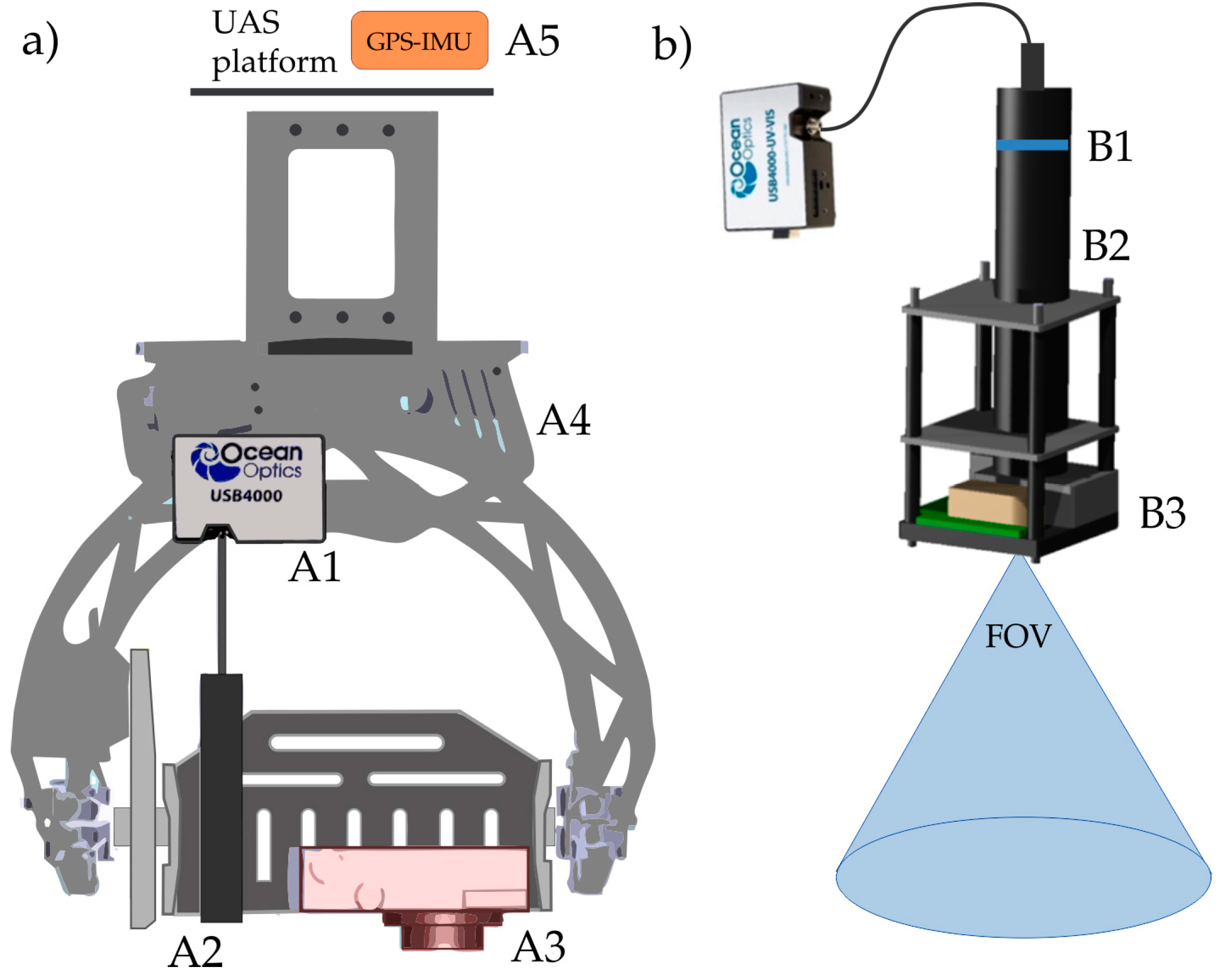
The payload is specifically developed for field spectroscopy surveys and combines a high-resolution spectrometer with an RGB digital camera (Figure 2). The USB4000 (Ocean Optics Inc., Dunedin, FL, U.S.) is a non-imaging fiber optic spectrometer (weight 0.190 kg), which measures 3648 spectral bands from 350 to 1000 nm with a Full Width at Half Maximum (FWHM) of about 1.5 nm (Figure 2A1). The spectrometer is connected to a specifically-developed Entrance Optic Receptor (EOR) (Figure 2A2) through a 0.1 m-long fiber optic. The EOR (Figure 2b) is composed of a series of lens tubes and an iris diaphragm (Thorlabs, Newton, NJ, U.S.) (Figure 2B2) that allow adapting the spectrometer Field-Of-View (FOV) in the range between ~2.5° and ~15° (Figure 2B4). Consequently, the dimension of the area sampled at the ground can vary between 0.5 and 12 m considering a flight altitude ranging from 5 to 50 m. This optical setup, commonly referred to as Gershun tube, has a two-fold advantage of reducing the spectrometer acceptance angle and providing a more uniform spot measurement. The RDI131 shutter (Melles Griot, Rochester, NY, U.S.) (Figure 2B3), mounted at the end of the EOR, allows regular and systematic measurement of the spectrometer Dark-Current (DC). In fact, the DC signal can substantially change during flight data recording, mainly caused by changes of spectrometer Integration Time (IT) and sensor temperature, which can introduce uncertainty in retrieving accurate surface radiance and reflectance spectra.
The spectrometer IT can be either set manually or automatically during the flight in order to collect higher quality data at different light illumination conditions and surface albedo. The Integration Time Optimization (ITO) algorithm [50] is implemented to set the IT automatically on the basis of the intensity of the surface reflected radiance observed at the different wavelengths. In this way, it is possible to maximize the spectrometer dynamic range and, consequently, the signal-to-noise ratio. Furthermore, light intensity can be optimized by placing neutral density filters (Thorlabs Inc., Newton, NJ, U.S.) in the EOR (Figure 2B1). These filters can be used to avoid spectrometer saturation for very high light intensities (i.e., measurements over high albedo surfaces such as snow-covered areas) and to achieve optimal spectrometer IT compatible with platform speed during data collection.
The PowerShot S100 (Canon, Tokyo, JAP) (Figure 2A3) is a compact RGB digital camera with a 12.1 Megapixel CMOS sensor that records high-resolution images (4000 × 3000 pixels). The camera FOV calculated considering the minimum focal length of the zoom lens (5.2 mm) and the physical dimension of the sensor (7.5 × 5.6 mm, 1.87 µm pixel size) is 71.5 × 56.6 degrees. Therefore, the camera captures an area of 14.42 × 10.77 m with a pixel resolution of 3.5 mm flying at 10 m over the target. The RGB camera is automatically triggered (1 image/s) during the flight, ensuring image overlapping of at least 80%. Both the RGB camera and spectrometer are installed on a stabilized gimbal (Photohigher AV200, CARVEC Systems, Hull, UK) (Figure 2A4) to reduce the impact of the mechanical vibrations on the scientific instruments.

2.3. Mission Planning and Data Collection

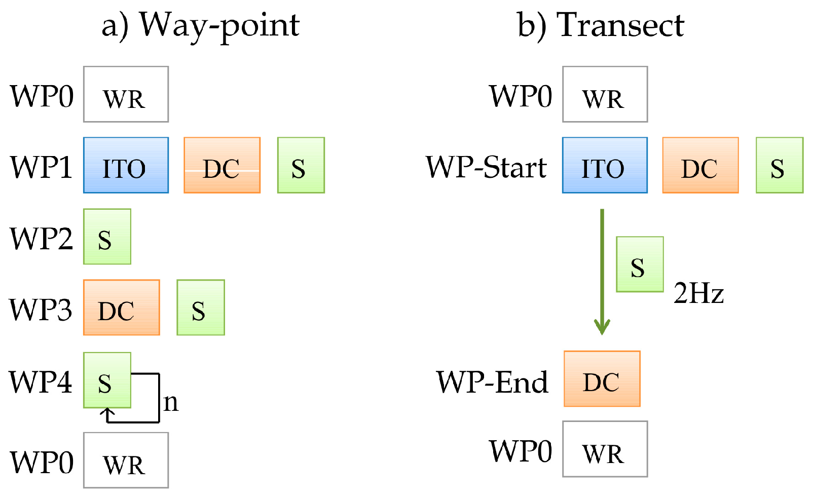
The mission planning is facilitated by a dedicated software supporting the matching between user observation requirements and platform/payload technical parameters (i.e., flight altitude, sampled areas, overlapping, etc.). As the first step, reference images of the investigated area (e.g., Google Earth or similar) are uploaded into the Graphical User Interface (GUI), and the so-called flight-space is defined (i.e., surface area and maximum flight height). Afterwards, the overall flight-plan is automatically calculated as a series of Way-Points (WPs), connected by line segments, covering the entire study area considering a certain level of RGB images overlapping (e.g., 80%). This approach is particularly helpful to achieve a systematic sampling on a regular grid to produce a 3D surface model, orthophoto or thematic maps. Once the base flight-plan for RGB imagery has been defined, the specific information related to spectrometer measurements can be edited. Two approaches are available (Figure 3): (i) in the way-point mode, the HyUAS hovers over each WP until all of the defined operation are completed (i.e., ITO, DC and target surface measurements); (ii) in the transect mode, the HyUAS collects continuous spectral measurements while it flies along a spatial transect between two defined WPs. The White Reference (WR) measurement, typically used to calculate surface reflectance, can be collected including WPs’ measurements over a reference tarp (i.e., WP0 in Figure 3). A different approach to collect WR was developed measuring the incoming irradiance using a second spectrometer operated at the ground (see Section 3.1.2 for details).
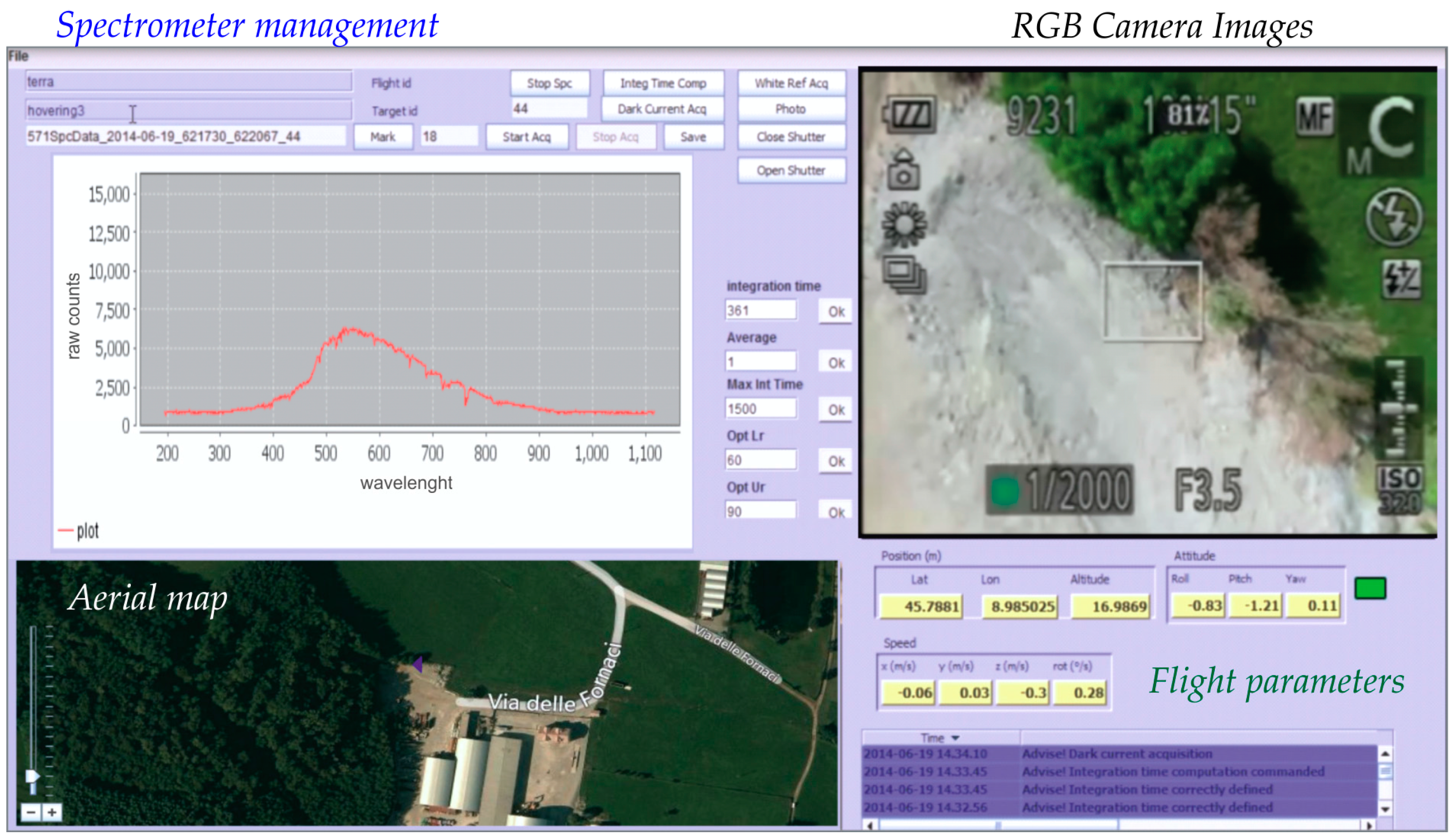
Flight operations can be monitored and controlled in real time by the mission control software running on the ground control station. The GUI displays the current spectral signature, the RGB image and the flight parameters (Figure 4). These data are useful to have an overview of flight operations and measurements. The software provides also the possibility to operate the HyUAS manually whenever needed. Each spectrum is associated with the corresponding RBG image and a set of navigation data that is used in the data processing. In particular, the following data are stored in a log file (.csv): spectrum file names, target identification name, GPS data (latitude, longitude, elevation), IMU data (relative position, roll, pitch, yaw, vertical and horizontal speeds) and RGB filenames.

3. Material and Methods

3.1. Data Processing

3.1.1. 3D Surface Model and Geo-Location of Spectra

RGB images were processed with Structure from Motion (SfM) algorithm [18] implemented in the Agisoft PhotoScan© software package. The 3D point cloud was created exploiting the overlapping between repeated RGB images [16]. This point cloud was then interpolated to create a Digital Surface Model (DSM) and a geo-referenced orthophoto.
The area sampled by the spectrometer was identified for each collected spectrum. This calculation was performed considering roll and pitch angles and the distance from the target measured on DSM. Afterwards, the exact area sampled by the spectrometer was projected on the orthophoto draped on the DSM. This process provides an accurate geo-location of spectra that is particularly relevant for improving the interpretation of reflectance signatures (especially over structurally complex or heterogeneous surfaces).

3.1.2. Retrieval of Surface Reflectance and Fluorescence

A dedicated software package was developed for processing spectra in a systematic way. The routines, implemented in the MATLAB® language, include a set of standard operations to process the spectroscopy data: (i) convert spectrometer raw counts to radiance spectra following standard processing methods (i.e., DC subtraction, non-linearity correction, radiometric and spectral calibrations); (ii) calculate surface reflectance, widely-used spectral indices and SIF.
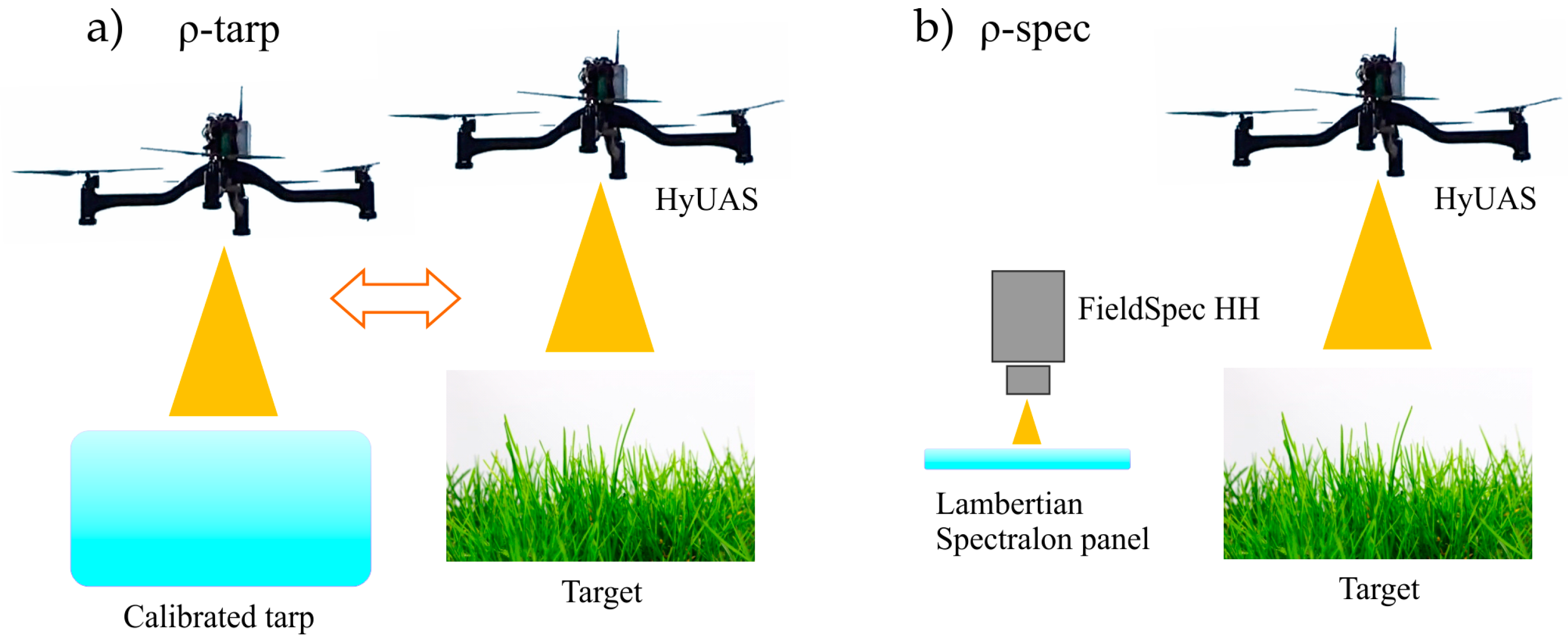
Two methods were tested to estimate surface reflectance ρ ( λ ) from HyUAS (Figure 5). They mainly differ in the measurement of the incoming radiance term L inc ( λ ) .
The first approach (ρ-tarp) uses only the HyUAS spectrometer measurements (Figure 5a). In fact, L inc ( λ ) is collected directly from UAS over a calibrated tarp (6 × 6 m) at least twice for each flight: immediately after take-off and after target measurements (before landing). A linear interpolation is applied to estimate L inc ( λ ) exactly at the time of target radiance measurements L ref ( λ ) . This approach limits errors in retrieving surface reflectance due to slight changes of illumination that can be caused by variations of the Sun zenith angle. In case of vegetation, L ref ( λ ) includes the additive contributions of canopy reflected radiance and fluorescence.
The second approach (ρ-spec) relies on a dual-spectrometer method [56,57] (Figure 5b). L inc ( λ ) measurements are recorded simultaneously by a second spectrometer operated at the ground over a typical Spectralon® panel during HyUAS measurements. L inc ( λ ) is measured continuously (i.e., every 0.5 s) by the ground FieldSpec HandHeld (HH) spectrometer (ASD Inc., Boulder, CO, U.S.). Dark-current measurements are acquired routinely every few minutes through the integrated shutter. We synchronized the timestamp of the two spectrometers before the flights. The surface reflectance is thus retrieved by matching spectra collected by the two instruments: L inc ( λ ) by ground spectrometer and L ref ( λ ) by HyUAS. The spectral characteristics of the ground spectrometer (i.e., spectral range, sampling and FWHM) should be as much as possible comparable to those of the USB4000 aboard the HyUAS in order to limit the formation of signal artifacts (i.e., spikes). Typically, these errors are more pronounced around major absorption features, such as the O2-band used to retrieve fluorescence. However, we implemented radiometric and spectral cross-calibration methods between the two spectrometers to limit errors on surface reflectance and fluorescence as much as possible. In the laboratory, we cross-calibrated the spectrometers radiometric responses considering a range of light intensities typical for clear-sky days during summer. In the field, we used the empirical correction method proposed in Bachmann et al., 2012 [58]. It consists of determining the actual spectral transfer function between two spectrometers. In practice, the spectra are resampled to a common wavelength-grid through linear interpolation; afterwards, Equation (1) is used to compute surface reflectance:
ρ spec = L ref HyUAS ( λ ) L inc gnd ( λ )   L inc gnd ( λ ) L inc HyUAS ( λ ) ,
The superscript indicates radiance spectra measured by the ground (gnd) or HyUAS spectrometer. The first term represents the surface reflectance computed as the ratio between HyUAS targets radiance L ref HyUAS and ground-spectrometer irradiance measurements L inc gnd . These spectra are acquired while the UAS is flying over different investigated targets. The second term represents the instruments transfer function derived as the ratio between simultaneous irradiance measurements collected by the two spectrometers at the moment of take-off. It must be remarked that the instrument transfer function is valid for a short timeframe, until the absorption features’ depth in the irradiance spectra do not change much. Therefore, spectral measurements were collected around noon with clear-sky conditions, and the transfer function was frequently estimated. The same approach was also used to correct radiance spectra L ref HyUAS needed to retrieve sun-induced fluorescence.
The reflectance signatures were used for calculating a number of widely-used vegetation indicators (Table 1): (i) the Normalized Difference Vegetation Index (NDVI), related to vegetation greenness [59]; (ii) the MERIS Terrestrial Chlorophyll Index (MTCI), linked to chlorophyll content [60]; (iii) the Photochemical Reflectance Index (PRI) [61] and the SIF [62] ,related to canopy photosynthetic activity. In fact, fluorescence emission is directly released within the core of the photosystems; it represents the fraction of radiation absorbed by leaves that exceeds the photosynthetic demand. An alternative and competitive way to dissipate excess light energy is represented by the Non-Photochemical Quenching (NPQ) process through the xanthophyll cycle activation. The PRI index allows tracking the interconversion of the xanthophyll pigments’ pool (i.e., violaxanthin, antheraxanthin and zeaxanthin) based on reflectance changes at 531 nm.
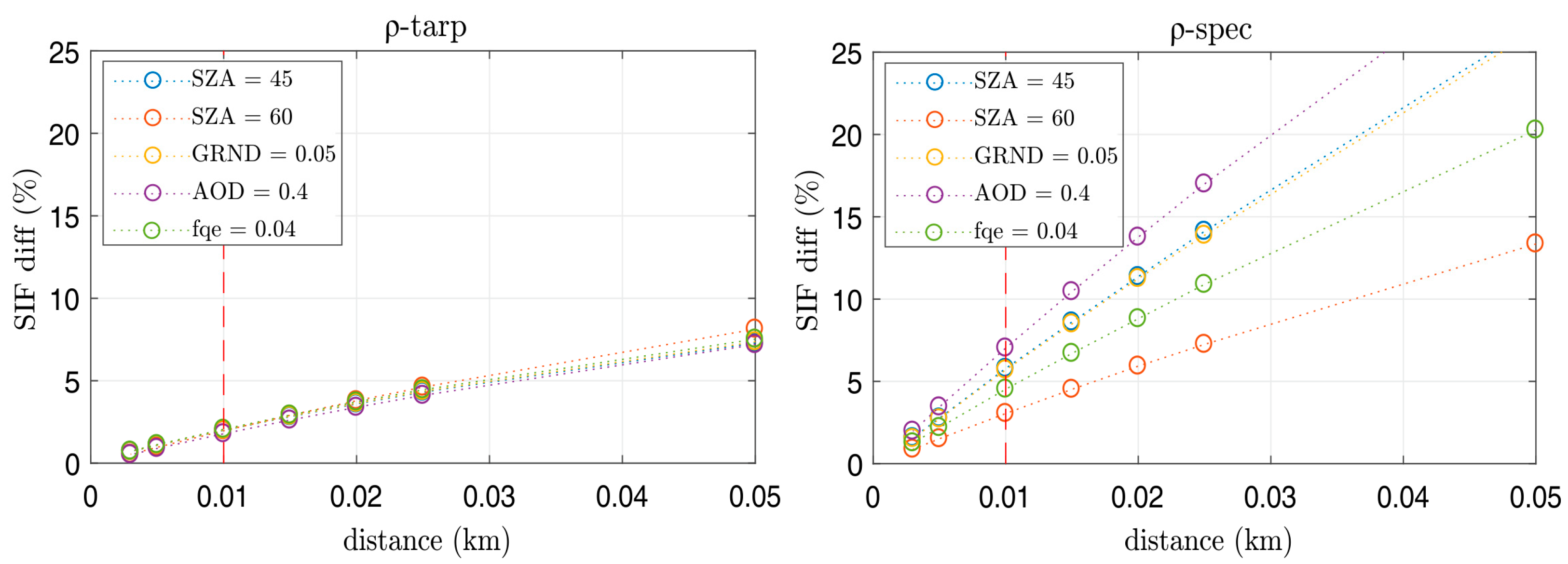
The first three indices can be easily calculated from the reflectance signature, while SIF retrieval requires more complex techniques. The SIF retrieval methods are generally based on the analysis of the radiance spectra at the oxygen absorption bands located at 760 nm (O2-A) and 687 nm (O2-B) [62,64]. In particular, we computed the far-red fluorescence comparing L inc ( λ ) and L ref ( λ ) spectral radiance inside and outside the O2-A band, according to the widely-used 3FLD (Fraunhofer Line Depth) approach [8,63]. We limited our analysis to the O2-A band because the spectral resolution offered by the USB4000 spectrometer can still provide meaningful results at this broader spectral feature [8,65]; conversely, it is not suitable for retrieving fluorescence at the narrower O2-B band. Although the HyUAS measurement approach is very similar to the typical field spectroscopy method, we carried out radiative transfer simulations to assess the impact of atmospheric effects in the limited path length between the target surface and the HyUAS sensor (typically 10 m). The analysis was carried out based on surface-atmosphere-coupled radiative transfer simulations by means of atmospheric MODerate resolution TRANsmission (MODTRAN5) code [66] and the Soil Canopy Observation Photosynthesis Energy balance (SCOPE) model [67]. The 4-flux coupled surface-atmosphere scheme has been implemented as described in [64,68], considering a Lambertian surface. This approach includes direct and diffuse target radiance, atmospheric path radiance and contribution from the surroundings (adjacency). We considered a restricted number of atmospheric and canopy parameters to limit the total number of simulations. The “standard” case of 19 described in [64] was used as the baseline; thus, we considered different O2-A band depths and fluorescence values to compare a wider range of environmental conditions. In particular, Aerosol Optical Thickness (AOT) varying between 0.1 and 0.4, ground-altitude between sea surface level to 0.15 km (proxy of surface pressure) and solar zenith angles of 30°, 45° and 60° were considered in MODTRAN. We include two fluorescence levels by changing the fluorescence quantum efficiency (fqe) from the default value of 0.002 to 0.004 within the SCOPE model. The reflectance was not changed because its spectral behavior around the O2-A band is smooth; therefore, its relative contribution to wavelengths used to retrieve fluorescence is very limited. The simulations were carried out considering HyUAS flight heights: 0.050, 0.025, 0.015, 0.010, 0.005, 0.003 km. The synthetic radiance spectra were resampled to HyUAS spectrometer bands to provide more realistic analysis for our experimental measurements. The L inc and L ref simulated at the surface level were used to compute fluorescence as measured by a ground-based spectrometer (free of an atmospheric effect). The ρ-tarp method was simulated considering canopy L ref HyUAS and reference tarp L inc HyUAS radiances as measured by HyUAS at different altitudes from the surface. The ρ-spec approach was instead simulated by combining L inc at the ground (ground spectrometer) and L ref HyUAS from HyUAS. The fluorescence computed by means of the ρ-tarp and ρ-spec methods at different altitudes was thus compared to the reference values at the ground.

3.2. Laboratory Characterization and Calibration

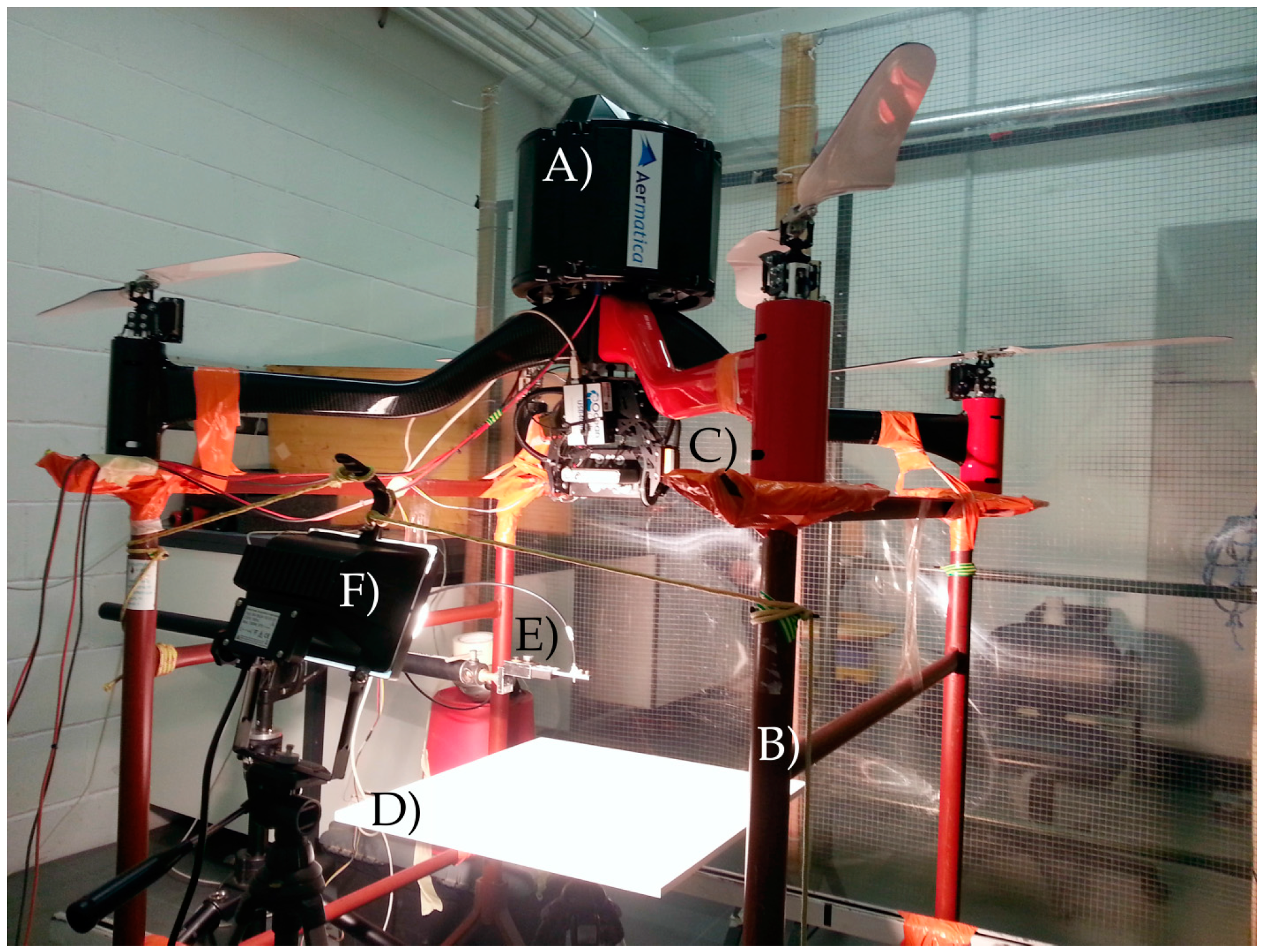
Dedicated laboratory tests were performed to characterize and calibrate the geometric, radiometric and spectral parameters of the HyUAS. The geometric, radiometric and spectral stability were verified during in-flight conditions. In fact, platform mechanical vibrations can affect optical interfaces and the spectrometer in terms of band centers, width and radiometric response. For this reason, a dedicated test-bed was realized to simulate typical in-flight conditions (Figure 6). This setup enables turning on engines, allowing the platform to slightly lift-off from its support (i.e., less than 1 cm) and keeping the payload centered on the test-bed, during the collection of spectral measurements. This way, typical flight maneuvers can be simulated in the laboratory under controlled conditions: taking-off (i.e., maximum thrust), hovering (i.e., minimum thrust) and flying between way-points. Spectral measurements were acquired before, during and after a series of repeated flight simulations, and the stability of spectrometer parameters was evaluated.
The geometric test aims to characterize the spectrometer FOV, in terms of acceptance angle degrees, and to identify the center of the sampled area (footprint) in the co-registered RGB image (i.e., x, y pixel). The test was carried out using a specific laboratory setup: the terminal part of the fiber optic, generally connected to the spectrometer entrance, was temporally detached and connected to the HL2000 halogen light source (Ocean Optics Inc., Dunedin, FL, U.S.) through the SMA905 interface. This allows feeding the optical system (i.e., light goes through fiber optic and EOR), projecting FOV on a flat and levelled surface placed at a 0.4-m distance. RGB images were collected, and the diameter of the spectrometer sampling area (illuminated circle) was measured by counting the number of illuminated pixels on the RGB image. This value was converted to physical units by using a referenced chessboard to correct typical camera lens distortions, and the FOV center within the RGB image was estimated.
The radiometric calibration required to convert raw digital counts to the radiance spectrum (W m−2 sr−1 nm−1) was achieved by cross-calibration with a reference, well-calibrated, FieldSpec HH spectrometer. Simultaneous measurements collected by the FieldSpec HH and HyUAS spectrometer were collected over a calibrated Lambertian Spectralon® panel placed in the test-bed and illuminated by a stabilized halogen lamp.
The center (maximum wavelength) and width of the spectral bands detected by the HyUAS spectrometer were characterized according to standard laboratory methods pointing the CAL-2000 Mercury-Argon (Hg-Ar) calibrated light source (Ocean Optics Inc., Dunedin, FL, U.S.) directly at the entrance of the EOR optics. The CAL-2000 lamp emits very narrow and sable lines in the VNIR spectral domain, whose maximum wavelengths and widths are well known. The band center and the FWHM were derived following Cogliati et al. [50]; the method mainly relies on fitting Gaussian functions to the narrow spectral peaks observed in the HyUAS spectral measurements.
For all of these tests, measurements were collected during repeated flight simulations to evaluate the sensitivity of instruments’ spectral and radiometric responses to possible misalignments of mechanical interfaces caused by platform vibrations.

3.3. Flight Campaign

The flight campaign was performed on 18 July 2014 to test the overall performances of HyUAS in a realistic scenario. Data were collected on a small area (0.3 km2) close to Gironico (Como, Italy, Lat 45.7878°, Lon 8.9840°). The area was characterized by different anthropogenic and natural land cover types, such as asphalt roads, gravel and sand of a small pit, agricultural corn field, meadow and a small forest. The latter is a mixed forest with trees of different species: the dominant plant is Robinia pseudoacacia together with few trees of Quercus sp. Way-point and transect data collection modes were employed to record spectral data during three consecutive flight sessions. For comparing different measurement approaches, we flew the HyUAS above the corn field at two flight altitudes (i.e., 10 and 20 m) using the way-point mode and at 10 m using the transect mode. The HyUAS flights were conducted around midday (12:30 to 13:30 local time) with almost clear sky to have higher radiance levels (i.e., better signal-to-noise ratio) and to limit the variation of incoming irradiance caused by changes in solar zenith angle. The spectrometer FOV was set to 6°. The absolute flight altitude from the ground level ranged between 10 and 35 m to keep almost the same sensor-surface distance of 10 m over the targets with different heights (e.g., meadow, asphalt and forest). In this configuration, the spectrometer samples an area of about 1.15 m, and the RGB camera captures an area of 14.42 m × 10.77 m with a pixel resolution of 3.5 mm.
Simultaneous ground-based spectral measurements were recorded with the FieldSpec HH following typical field spectroscopy techniques [69]. These measurements were collected only over a small group of targets because it was not practical to acquire measurements over higher canopies, such as forest and corn. The accuracy of spectral data collected by the HyUAS were assessed comparing radiance and reflectance signatures against ground-truth spectra. The statistical indices considered in the comparison were the Root Mean Square Error (RMSE), which quantifies the differences between retrieved values (i.e., HyUAS data) and assumed ground-truth (i.e., FieldSpec HH data), and the Relative RMSE (RRMSE%), which represents the percentage of error.

4. Results and Discussions

4.1. Geometric, Radiometric and Spectral Characterization

The geometric characterization was performed to quantify the spectrometer FOV, the footprint center and to assess the impact of platform vibrations on these parameters. Figure 7 shows the spectrometer sampling area (illuminated circle) as observed by the RGB camera. The mean and the standard deviation values were calculated from a sample of four images collected for each of the three repeated flight simulations (Table 2). The low standard deviation values demonstrate that platform vibrations during typical flight operations have a negligible effect on the geometric parameters. The standard deviations observed translate to an uncertainty of the footprint size and center lower than 10−2 m, considering a flight altitude equal to 10 m. Additionally, spatial transects of blue, green and red channels were extracted from the RGB images along the x and y directions (Figure 7). The shape similar to a square wave indicates good performance of EOR; in fact, most of the light reaching the spectrometer comes from the area defined within the footprint (not from the surroundings), and the detected signal is almost uniform.
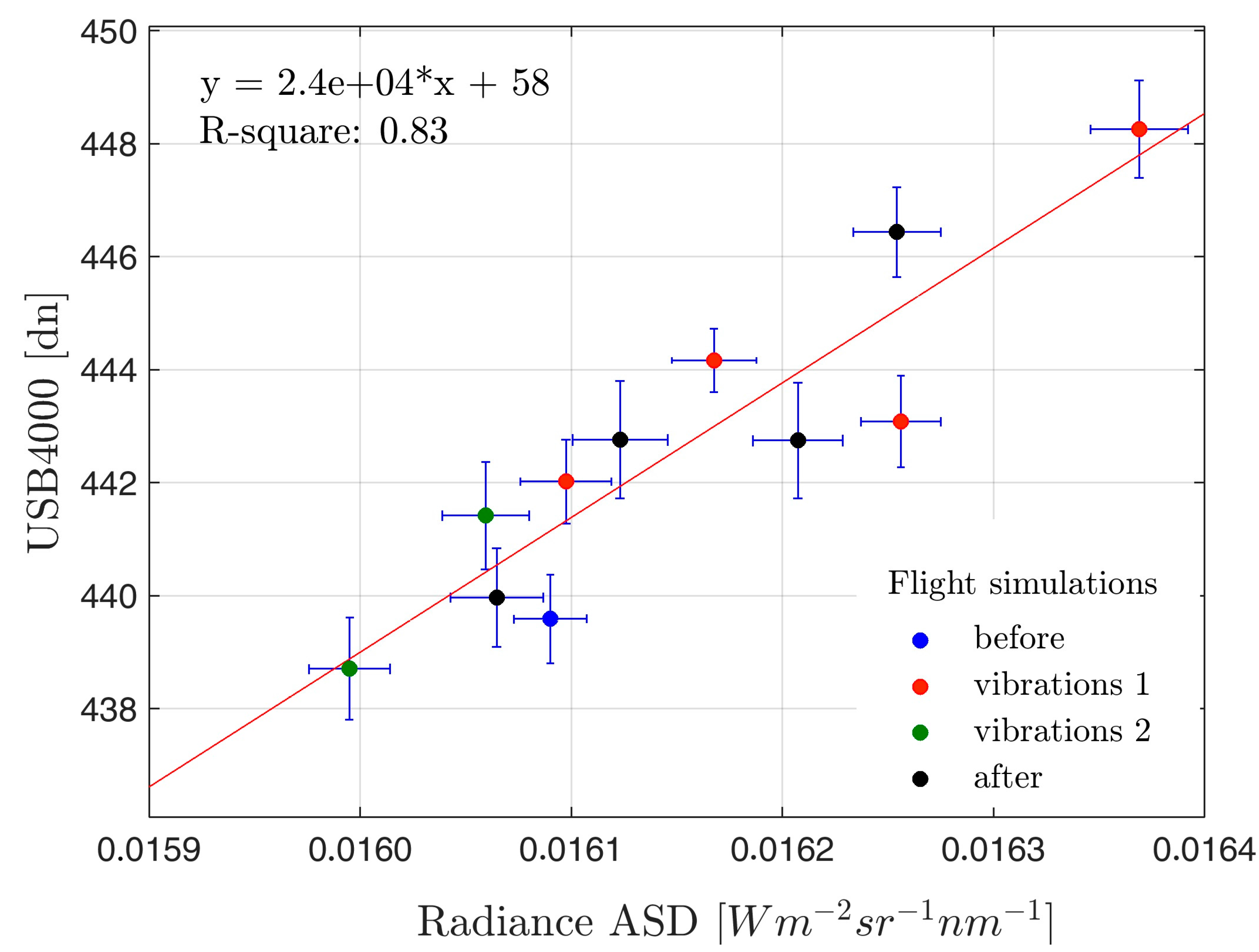
Data collected during the radiometric cross-calibration measurements were used to derive the radiometric calibration factors used to convert instrument raw counts to radiance units. Furthermore, the impact of platform vibrations was evaluated by comparing signals measured with and without platform vibrations. The signal measured by the HyUAS spectrometer during the in-flight condition shows variations lower than 10 digital counts for USB4000 and lower than 10−3 radiance units (W m−2 sr−1 nm−1) for FieldSpec HH. In particular, Figure 8 shows that the two signals are linearly correlated (R2 = 0.83). Probably, these small variations are mostly caused by slight fluctuations of radiance emitted by the light source and not by the vibrations of the rotor. The comparison was made at 628 nm to exploit the maximum dynamic range of the spectrometer, but similar results were observed for other wavelengths recorded by the spectrometer.
The applied spectral characterization methodology allowed computing the wavelength vector (i.e., absolute wavelength for each spectral band) and to characterize the instrument FWHM. Figure 9a shows the narrow lines emitted by the CAL-2000 light source detected by the HyUAS. The absolute differences between maximum peaks’ wavelength before and during the vibrations are depicted in Figure 9b. The maximum difference found is about ±0.1 nm. It was observed at 404, 696 and 800 nm, and it can be considered negligible compared with the spectrometer’s FWHM of 1.5 nm. This result demonstrates the good spectral stability of the HyUAS because spectral peaks detected during in-flight measurements were not significantly shifted nor broadened by platform vibrations.

4.2. Analysis of the Retrieved Reflectance and Fluorescence

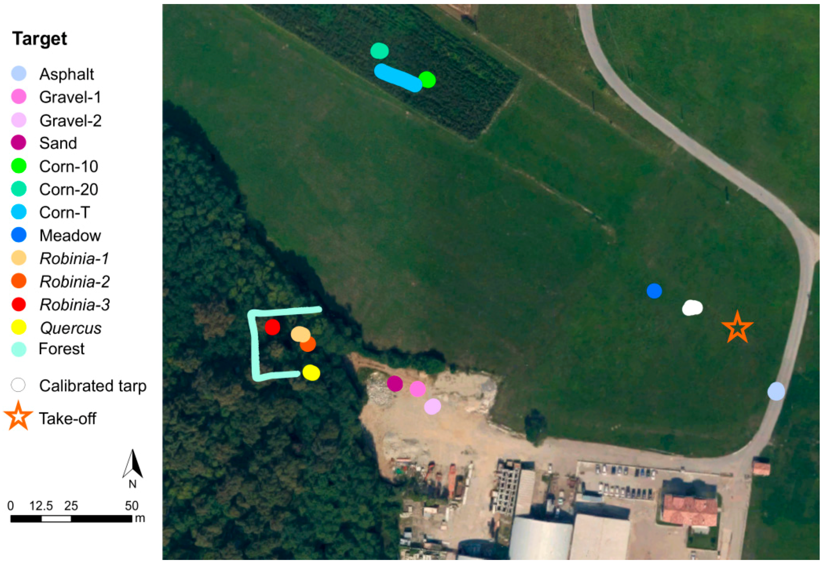
Spectral signatures of different land cover classes were collected during a flight campaign to verify the reliability of HyUAS radiance, reflectance spectra and far-red SIF at 760 nm. The overall location of way-points and continuous transect measurements in the study area are depicted in Figure 10.
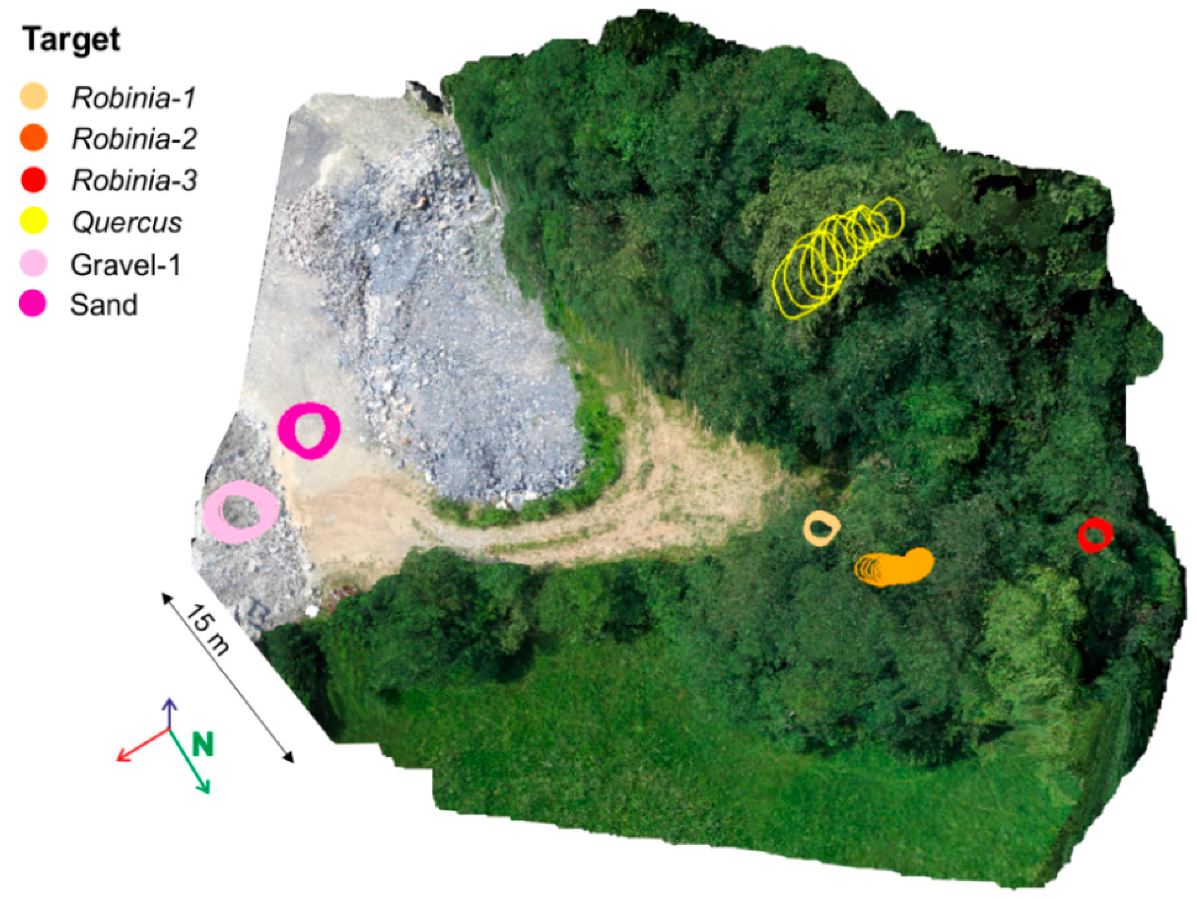
Figure 11 shows the orthophoto draped on the DSM, derived by combining RGB images and platform navigation data of a subset area over the forest patch. The mixed forest looks well represented by the model: single trees can be clearly recognized, as well as their shape and their relative different heights. The height of the plants varies in the range of 13 to 22 m, and the crown size is about 5 m, as estimated from the model. The 3D model created with Photoscan indicates a camera location total error of about 0.60 m. It was calculated by the software as the differences between initial and camera positions projected after model calculations (x, y, z coordinates were considered for all of the images used to create the model). However, the accuracy of geographical coordinates in absolute terms is not critical for the purposes of our work. Rather, the spatial consistency between the 3D surface model and the spectral point measurements is much more relevant. This is strengthened by the fact that HyUAS navigation data are recorded with an acquisition rate at least 10-times higher than RGB camera and spectrometer sampling. The basic signal processing technique were applied to filter and integrate high-frequency measurements, reducing uncertainties in geo-locating spectral measurements.
The attitude of the HyUAS varies during flight while spectra measurements were collected. In particular, pitch and roll caused a variation of the area sampled by the spectrometer at the ground. We observed that during the way-point mode (i.e., hovering), roll and pitch angles varied 1.4° (±1.2°); therefore, the sampled area is very close to, or completely overlapped, the area viewed from nadir. Differently, roll and pitch angles show variations of 3° (±2°) during the transect measurements with larger displacements of the area sampled by the spectrometer. These effects account for the aforementioned geo-location processing of spectral measurements. Figure 11 shows the spectrometer sampling area (circular shape) projected over the different targets after the geo-location process. Over almost flat surfaces, the projected spectrometer FOV is close to a circle, while on rugged surfaces (e.g., rough canopy surface), the sampled area is displaced as an irregular shape. Geo-location of spectral measurement improved considerably the interpretation of spectral signatures, especially during continuous measurements. For example, knowing exactly the area sampled over the forest was fundamental in the interpretation of spectral measurement described in the next paragraph.
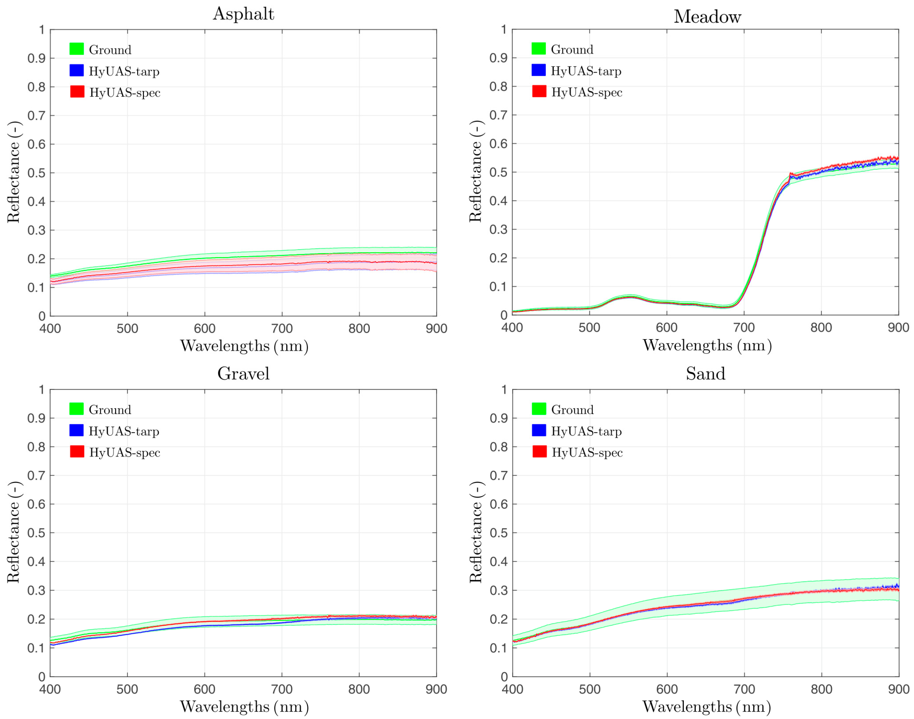
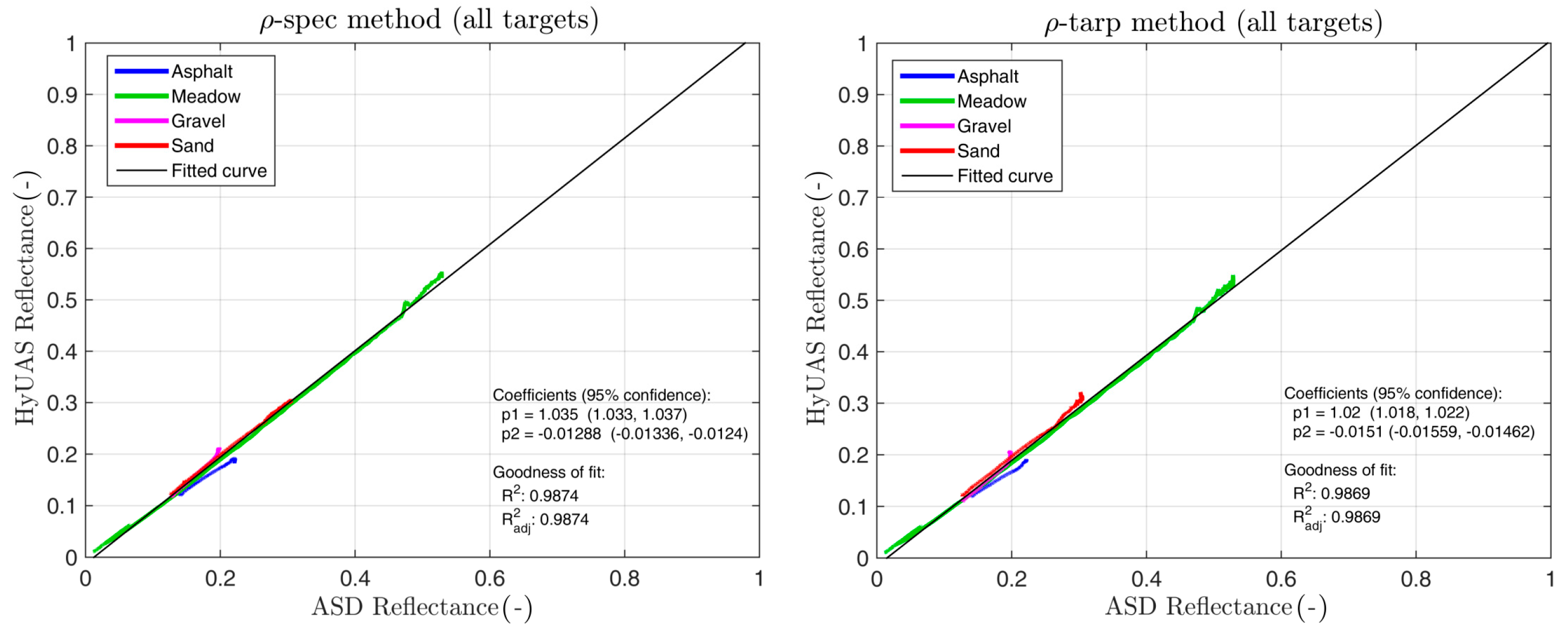
The reflectance signatures estimated by HyUAS were compared with those collected at the ground by using the FieldSpec HH spectrometer over accessible targets (i.e., meadow, sand, gravel and asphalt), hereafter “ground-truth”. Figure 12 shows a good agreement between ground-truth (green line) and reflectance signatures estimated from HyUAS considering both the ρ-tarp (blue line) and ρ-spec (red line) methods. In particular, spectral signatures collected by HyUAS show standard deviations comparable with ground-truth spectra. We found that, for all of the spectral bands and for all targets, reflectance measured with the HyUAS exhibits a high linear correlation (R2 = 0.98 for both methods) compared to those measured at the ground with the FieldSpec HH (Figure 13).
The RMSEs and the RRMSEs values calculated between ground-truth and HyUAS spectra are shown in Table 3. Considering all targets, RRMSE values are lower than 15% and 10% for radiance and reflectance, respectively. The ρ-spec method shows lower RMSE and RRMSE compared with the ρ-tarp methods. In particular, RRMSE values are equal to 7.88% and 9.62%, respectively, demonstrating a good accuracy and the reliability of HyUAS spectral measurements.
Some practical considerations can be delineated in the process of collecting data and calculating reflectance between the ρ-tarp and ρ-spec methods. In order to collect incoming solar irradiance measurements, the first method required a calibrated tarp placed over a flat terrain in the study area. This requirement could be difficult to satisfy in certain scenarios (e.g., surveys in mountain rugged areas). Furthermore, the mission-plan is more complex because incoming solar irradiance must be frequently measured to assure reliable reflectance computations. Using the dual spectrometer approach, continuous measurements of solar irradiance are obtained using a calibrated Spectralon® panel. This approach is preferred for measurements during not completely stable illumination conditions. On the other hand, the ρ-spec method requires a fine spectral and radiometric inter-calibration between the two spectrometers together with the use of the empirical transfer function as previously described in Section 3.1.2.
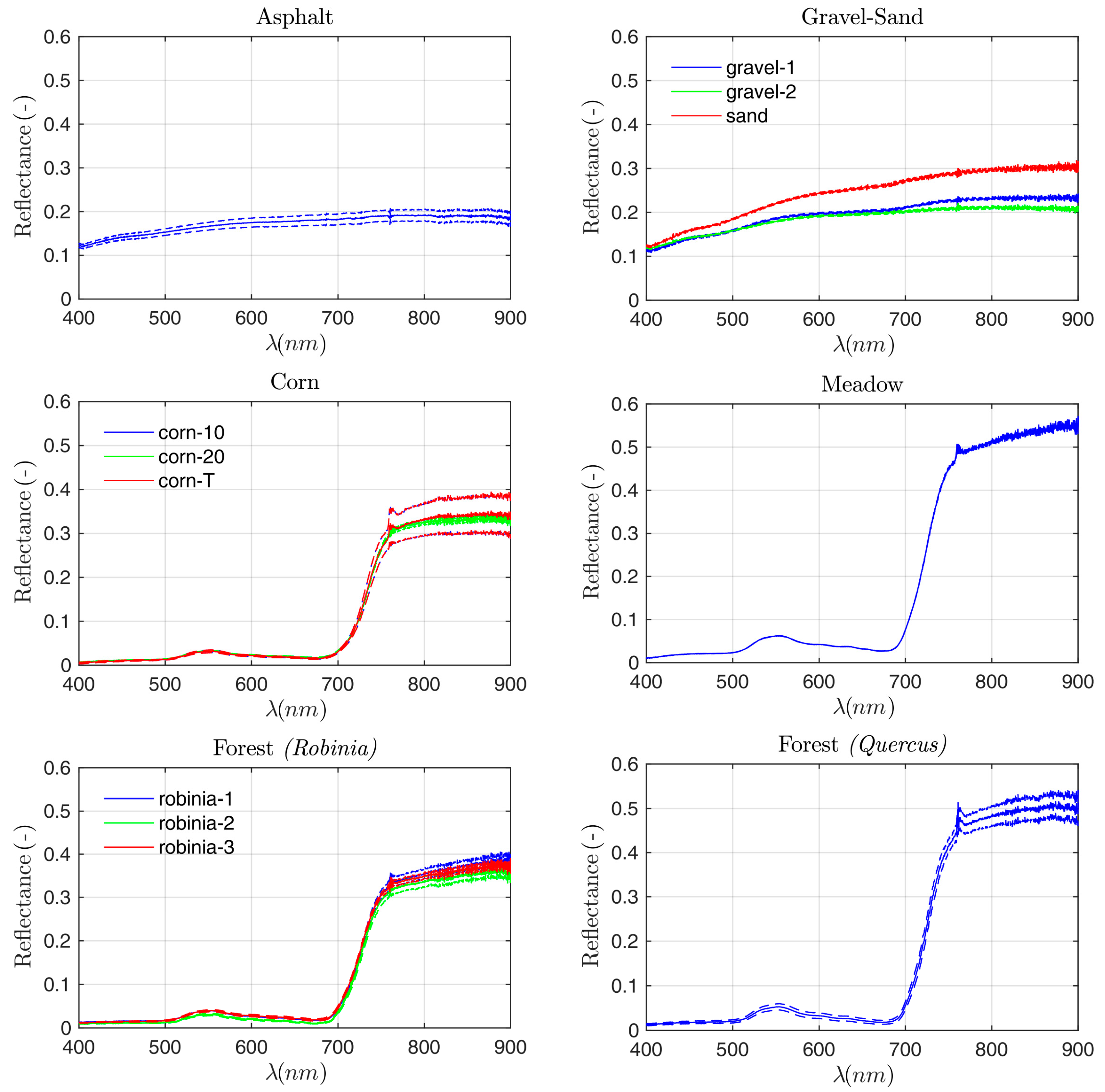
The analysis of spectral reflectance collected on the entire set of land cover types in the study area is shown in Figure 14 and discussed in this section. Asphalt and gravel show the expected spectral behaviors, and the signatures observed refer to different types of gravel characterized by different colors (e.g., mineral composition). The vegetated targets show the typical reflectance signatures characterized by: chlorophyll absorption in blue and red spectral regions, the characteristic sharp increase of reflectance in the red-edge and high scattering in the NIR. The peak caused by in-filling of sun-induced fluorescence at the O2-A band is evident in the apparent surface reflectance of all vegetated targets. Corn, meadow and forest show their own different reflectance signatures. This proves the potential capability of HyUAS to identify different vegetation types. Furthermore, the corn field was observed with a different setup: in way-point mode from a 10- to 20-m distance above the canopy (blue and red line, respectively); along a spatial transect at 10 m above the canopy (green line). These approaches show similar average reflectance, but different standard deviations. In particular, the canopy reflectance spectra derived from 10 m, either by the way-point or transect measurement approach, have a larger standard deviation due to the fact that spectrometer FOV projected on the target (diameter = 1.15 m) covers a single crop row and part of the bare soil. From this distance, in fact, small variations of pitch and roll angles might cause larger variations on the relative amounts of canopy and bare soil. Instead, the area viewed at a 20-m distance from the canopy (diameter = 2.30 m) includes at least two crop rows and a smaller portion of bare soil between them. The soil contribution is lower in this case; therefore, the radiometric signal sampled during repeated measurements is less subject to small changes of the platform location, roll and pitch angles, and consequently, the standard deviation is lower. This example shows a practical opportunity offered by HyUAS; in fact, the capability of collecting measurements at different distances from the target surface permits optimizing the sampling area size to reduce effects caused by surface heterogeneity or canopy-specific arrangements (i.e., agricultural crops row, clumping, etc.). The reflectance signature of meadow shows higher values mostly due to a lower chlorophyll content (visible wavelengths) and the particular canopy structure, which limits multiple-scattering effects (near-infrared). The points measured over the forest show very different reflectance signatures for the two trees species. The average spectra and standard deviation of measurements collected on three different trees of Robinia pseudoacacia show very similar values. The variability of measurements on the Quercus sp. tree is larger; this could be due to the higher spatial heterogeneity recorded through the transect mode. Despite such large variability in Quercus sp. data, the reflectance spectra related to these two plant species can be clearly distinguished.
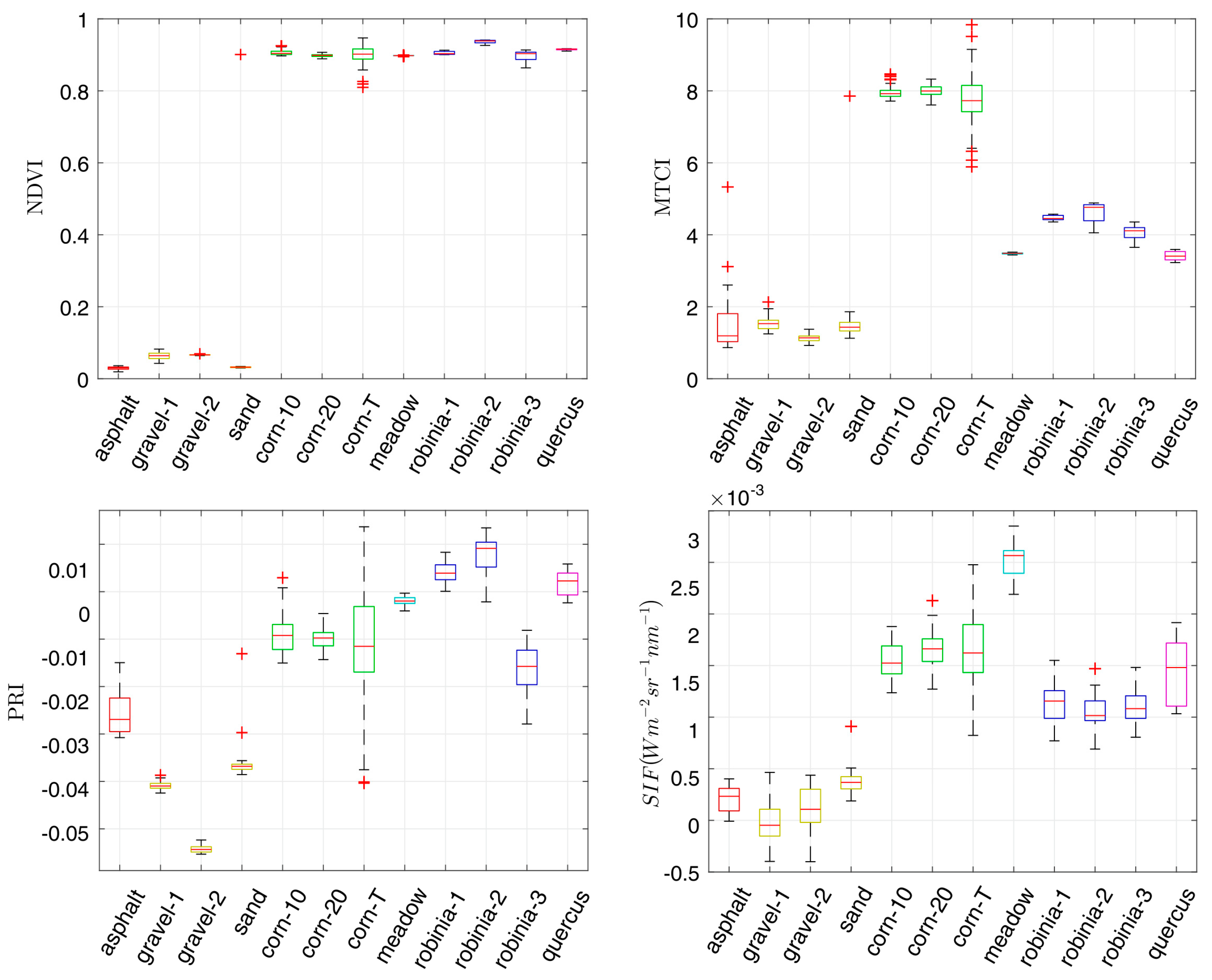
The boxplots in Figure 15 show some of the spectral indicators widely used in vegetation studies. NDVI is mostly related to biomass and greenness; in fact, the values observed are close to zero for non-vegetated targets (i.e., asphalt and gravel), whereas higher values ranging between 0.8 and 0.9 were found for corn, meadow and forest. The canopy chlorophyll content as detected by MTCI shows the same general trend characterized by lower values for non-vegetation targets, but in this case, the values related to different vegetation types are much more diverse. The corn is characterized by the highest values; this is probably due to its higher chlorophyll content compared to natural ecosystems. In fact, agricultural practices have the objective of optimizing crop yield in terms of biomass and consequently chlorophyll content. The same pattern cannot be clearly observed by NDVI because of the well-known saturation effect and its limited sensitivity in dense vegetation [70,71]. It is worth noting that spectral indices derived from measurements collected on the corn field at different flight heights exhibit the same behavior described earlier for the reflectance signature. In fact, the median values are similar while the dispersion of data is larger for measurements collected at a 10-m distance. PRI is sensitive to the dissipation of the excess of light energy absorbed by chlorophyll through the activation of the xanthophyll cycle. In general, lower PRI values indicate a larger activation. The complete interpretation of this process is non-trivial because both the total pool of xanthophyll pigments and the canopy structure strongly affect the overall magnitude of the signal detected at top-of-canopy. Therefore, an exhaustive and detailed interpretation of PRI is very challenging, and it is not the main aim of this study. However, it is interesting to underline how PRI values detected by HyUAS on different targets are diverse, opening perspectives of exploiting PRI detected by HyUAS in vegetation monitoring studies.
SIF is considered a close proxy of photosynthetic activity because this signal arises from plant photosystems. The total magnitude of SIF is also driven by a number of factors, among which the overall amount of green biomass, the chlorophyll content and the incoming irradiance level. Therefore, an effective interpretation of SIF needs to consider the specific characteristics of the canopy and illumination conditions, thus complicating the comparison between different types of vegetation and measurement on different days. The SIF retrieval is much more difficult compared to reflectance-based indices, because the amount of fluorescence emitted by the plant is very small compared to the overall backscattered radiance in the NIR. In fact, SIF represents only a few percent of the total signal. Thus, even small errors in the retrieval algorithm generally translate into large bias on SIF (retrieved SIF could be orders of magnitude larger than the expected value). SIF of non-vegetated targets show very low values, which are almost close to zero. The residual error is lower than a few-tenths of mW m−2 sr−1 nm−1, and it is probably caused either by slight changes of the reference irradiance spectrum or errors introduced from the 3FLD method. The SIF values retrieved for vegetated targets are higher and fall in the range of values obtained by field spectroscopy measurements reported in the literature [9,48,49,50,65,72,73]. The obtained results strongly agree with the findings of Rossini et al. [73]. In that paper, the authors provide a comprehensive review of ground-based fluorescence measurements on a wide range of vegetation species. In particular, our results are strongly in agreement with general statements drawn in the conclusions of their work: (i) SIF values are in the range of 0 to 3 mW m−2 sr−1 nm−1; (ii) the highest values were measured on crops and meadow followed by broadleaf plants; (iii) the absolute values and uncertainties are very similar, even though the differences in plant species prevent a direct quantitative comparison. Although SIF is a highly dynamic signal, the comparison of our results with those reported in [73] is motivated by the fact that in both cases, spectral measurements were collected around noon during typical clear-sky days in summer at mid-latitudes. In these conditions, the illumination can be considered almost comparable, at least within a short timeframe around noon. Moreover, Figure 15 shows that fluorescence retrieved values for different vegetation targets have diverse averages, and the interquartile ranges allow discriminating almost all of the different species. The Quercus sp. and Robinia are partially overlapped because the Quercus sp. sample shows a pretty large dispersion of measurements, likely due to strong canopy directional effects. The SIF values retrieved by HyUAS are consistent with the vegetation indices presented: high SIF values were found for targets with higher NDVI and MTCI because, as previously mentioned, SIF strongly depends on the amount of green biomass and leaf chlorophyll content. The latter statement is not general, for example corn has a larger chlorophyll content than meadow, but canopy fluorescence is lower. This highlights the added information content brought from SIF: it is largely driven by chlorophyll content, but it also sensitive to actual photosynthesis and canopy re-absorption and scattering processes. Understanding all of these effects together is very complex, and methodologies based on a synergic analysis of the reflectance signature and fluorescence are under development.
To better understand the overall accuracy of fluorescence values retrieved, we used radiative transfer simulations to analyze the impact of atmospheric transmittance along the short radiation path between top-of-canopy and sensor. Figure 16 shows relative deviations of fluorescence retrieved at different altitudes by means of the ρ-tarp and ρ-spec methods compared to the reference value at the ground (SIF diff). The ρ-tarp method shows lower error because canopy radiance absorbed within the O2-A band is partially compensated by reference measurement collected on the tarp at the same altitude. The remaining error is lower than a few percent at a 10-m distance. It is related to multiple scattering and adjacency effects in the forward radiative transfer simulations, which were not considered in the 3FLD retrieval method. The ρ-spec method shows larger errors because the transmittance between the top of the canopy and sensor is not considered. The errors at a 10-m distance range between 4% and 8% for different atmospheric and fluorescence values considered. This error budget is somehow acceptable for the current state of development because: (i) it has a similar magnitude of measurement uncertainty for a single target (interquartile boxes in Figure 15); (ii) it complies with the 10% error budget required for FLEX mission products. Basically, atmospheric correction could improve the fluorescence retrieval accuracy, but currently-available algorithms are not yet consolidated for this type of measurement. On the other hand, even small errors in retrieving atmospheric parameters and the successive convolution to instrument spectral bands could introduce significant errors. Therefore, low-flying UAS could offer a more practical approach to collect spatially-distributed fluorescence measurements within a reasonable level of accuracy. However, more dedicated studies are required to further develop the UAS-based measurement approach and practical atmospheric correction algorithms to improve fluorescence retrieval accuracy.

5. Conclusions

This study presented a novel UAS to measure VNIR surface reflectance and far-red SIF at the O2-A band, co-registered with RGB images, for supporting field spectroscopy surveys in the framework of vegetation monitoring and calibration/validation activities of remote sensing data. The exploitation of HyUAS is facilitated by the software applications specifically developed for accomplishing mission planning, data collection and data processing. The characterization and calibration of geometric, radiometric and spectral parameters of the instruments, considering static and in-flight conditions, enabled accurate radiance, reflectance spectra and SIF at 760 nm. The laboratory tests demonstrated that in-flight platform vibrations do not significantly affect spectral measurements, even for the retrieval of the faint fluorescence signal. The results obtained during the flight test showed a good agreement between HyUAS and ground-based spectral measurements for the investigated land covers. For both the retrieval methods (ρ-tarp and ρ-spec), the RRMSE value was lower than 10%. The possibility of measuring spectral signals more related to the photosynthetic activity of plants, through PRI and SIF, has been demonstrated using this configuration. Although the estimation of SIF requires high-resolution spectrometers and accurate retrieval methods, the results obtained are promising to further develop this measurement approach. The radiative transfer simulations show that low-flying UAS allows measuring fluorescence with error lower than 10%. This fact opens relevant perspectives to employ similar UASs for monitoring vegetation photosynthesis characterized by high temporal dynamics. Further improvements will regard the much more difficult analysis of red fluorescence at the O2-B band, the use of advanced spectral fitting methods and the retrieval of biophysical products (i.e., leaf area index, chlorophyll content, etc.) needed for interpreting ecosystem productivity.
In general, the HyUAS was demonstrated to be a reliable system for supporting field spectroscopy surveys enabling the collection of spectral measurements in a more systematic and rapid way even on inaccessible targets (e.g., forest trees). HyUAS is able to provide relevant environmental data (i.e., VNIR radiance/reflectance, fluorescence and 3D surface model) observing the heterogeneity of land covers at different spatial resolution. In the context of calibration and validation activities, HyUAS enables monitoring the spatial heterogeneity of dedicated measurement sites, including their temporal dynamics during the vegetation growing season. For example, regarding the FLEX mission operating at a spatial resolution of 300 m, HyUAS observations distributed in space and time can provide fluorescence data for evaluating the natural variability of a single vegetation type within the measurement area. Alternatively, HyUAS represents a useful and efficient tool for upscaling measurements whether the validation site is characterized by a mixture of different land cover types and different temporal dynamics.
The HyUAS concept privileged spectral and radiometric quality of measurements, essential to enable accurate retrieval of PRI and SIF for advanced vegetation studies. In comparison, compact hyperspectral imaging sensors for UAS applications offer a more systematic spatial sampling that simplifies the production of thematic maps. However, the spectral resolution and signal-to-noise ratio of currently-available instruments are not optimal to retrieve SIF. In addition, the very high spatial resolution (e.g., few centimeters) produces very complex reflectance anisotropy patterns (e.g., leaf orientation and shadows), which make the correct interpretation of vegetation indicators challenging. This could be overcome by flying the sensor at a larger distance from the canopy, but the need for atmospheric correction to derive SIF arises. Therefore, imaging systems do not provide necessarily better results considering the current state-of-art of instruments and retrieval methods.
Concluding, the HyUAS constitutes a cost-effective instrument that can provide accurate, multi-scale and flexible spectral observations for vegetation monitoring studies. Furthermore, it could support the calibration and validation activities of the upcoming FLEX satellite, but it could be exploited also for assessing VNIR spectral bands of others optical satellite missions (i.e., Landsat, Sentinel-2 and Sentinel-3).

Acknowledgments

The research was supported by the SINOPIAE project funded by Regione Lombardia. The authors wish to thank the Aermatica S.p.A., P. Marras and B. Tattarletti for their collaboration, the Geomatic Laboratory (University of Milano-Bicocca, UNIMIB) and M. Celesti (UNIMIB) for the support in the field campaign, R. Gentili (UNIMIB) for the help in plant species identification and M. Anelli (UNIMIB). The authors are also grateful to the Editor and reviewers for their useful comments, improving the quality of the manuscript.

Author Contributions

All of the authors conceived of, designed and performed the laboratory experiments and the flight campaign. R.G. and B.D.M. performed the data processing and analysis. S.C. calculated and interpreted the vegetation indicators and SIF. R.G. wrote the first draft of the paper, with significant revisions provided by B.D.M., R.C. and S.C.

Conflicts of Interest

The authors declare no conflict of interest.

References

  1. Masek, J.G.; Hayes, D.J.; Hughes, M.J.; Healey, S.P.; Turner, D.P. The role of remote sensing in process-scaling studies of managed forest ecosystems. For. Ecol. Manag. 2015, 355, 109–123. [Google Scholar] [CrossRef]
  2. Morisette, J.T.; Privette, J.L.; Justice, C.O. Overview of Uav Activities in Wageningen Unmanned Aerial Remote Sensing Facility. Remote Sens. Environ. 2002, 83, 77–96. [Google Scholar] [CrossRef]
  3. Schaepman, M.E.; Ustin, S.L.; Plaza, A.J.; Painter, T.H.; Verrelst, J.; Liang, S. Earth system science related imaging spectroscopy-An assessment. Remote Sens. Environ. 2009, 113, S123–S137. [Google Scholar] [CrossRef]
  4. Meroni, M.; Colombo, R. 3S: A novel program for field spectroscopy. Comput. Geosci. 2009, 35, 1491–1496. [Google Scholar] [CrossRef]
  5. Milton, E.J. Review Article Principles of field spectroscopy. Int. J. Remote Sens. 1987, 8, 1807–1827. [Google Scholar] [CrossRef]
  6. Milton, E.J.; Schaepman, M.E.; Anderson, K.; Kneubühler, M.; Fox, N. Progress in field spectroscopy. Remote Sens. Environ. 2009, 113, S92–S109. [Google Scholar] [CrossRef]
  7. Arthur, A.M.; Robinson, I. A critique of field spectroscopy and the challenges and opportunities it presents for remote sensing for agriculture, ecosystems, and hydrology. Proc. SPIE 2015, 9637, 963705. [Google Scholar]
  8. Damm, A.; Erler, A.; Hillen, W.; Meroni, M.; Schaepman, M.E.; Verhoef, W.; Rascher, U. Modeling the impact of spectral sensor configurations on the FLD retrieval accuracy of sun-induced chlorophyll fluorescence. Remote Sens. Environ. 2011, 115, 1882–1892. [Google Scholar] [CrossRef]
  9. Rossini, M.; Meroni, M.; Celesti, M.; Cogliati, S.; Julitta, T.; Panigada, C.; Rascher, U.; Van der Tol, C.; Colombo, R. Analysis of Red and Far-Red Sun-Induced Chlorophyll Fluorescence and Their Ratio in Different Canopies Based on Observed and Modeled Data. Remote Sens. 2016, 8, 412. [Google Scholar] [CrossRef]
  10. Hilker, T.; Coops, N.C.; Nesic, Z.; Wulder, M.A.; Black, A.T. Instrumentation and approach for unattended year round tower based measurements of spectral reflectance. Comput. Electron. Agric. 2007, 56, 72–84. [Google Scholar] [CrossRef]
  11. Hilker, T.; Coops, N.C.; Coggins, S.B.; Wulder, M.A.; Brownc, M.; Black, T.A.; Nesic, Z.; Lessard, D. Detection of foliage conditions and disturbance from multi-angular high spectral resolution remote sensing. Remote Sens. Environ. 2009, 113, 421–434. [Google Scholar] [CrossRef]
  12. Drolet, G.; Wade, T.; Nichol, C.J.; MacLellan, C.; Levula, J.; Porcar-Castell, A.; Nikinmaa, E.; Vesala, T. A temperature-controlled spectrometer system for continuous and unattended measurements of canopy spectral radiance and reflectance. Int. J. Remote Sens. 2014, 35, 1769–1785. [Google Scholar] [CrossRef]
  13. Sakowska, K.; Gianelle, D.; Zaldei, A.; MacArthur, A.; Carotenuto, F.; Miglietta, F.; Zampedri, R.; Cavagna, M.; Vescovo, L. WhiteRef: A New Tower-Based Hyperspectral System for Continuous Reflectance Measurements. Sensors 2015, 15, 1088–1105. [Google Scholar] [CrossRef] [PubMed]
  14. Pacheco-Labrador, J.; Martín, M.P.; Riaño, D.; Hilker, T.; Carrara, A. New approaches in multi-angular proximal sensing of vegetation: Accounting for spatial heterogeneity and diffuse radiation in directional reflectance distribution models. Remote Sens. Environ. 2016, 187, 447–457. [Google Scholar] [CrossRef]
  15. Shugart, H.H.; Asner, G.P.; Fischer, R.; Huth, A.; Knapp, N.; Le Toan, T.; Shuman, J.K. Computer and remote-sensing infrastructure to enhance large-scale testing of individual-based forest models. Front. Ecol. Environ. 2015, 13, 503–511. [Google Scholar] [CrossRef]
  16. Colomina, I.; Molina, P. Unmanned aerial systems for photogrammetry and remote sensing: A review. ISPRS J. Photogramm. Remote Sens. 2014, 92, 79–97. [Google Scholar]
  17. Ma, L.; Li, M.; Tong, L.; Wang, Y.; Cheng, L. Using Unmanned Aerial Vehicle for Remote Sensing Application. In Proceedings of the 2013 21st International Conference on Geoinformatics, Kaifeng, China, 20–23 June 2013; pp. 1–5. [Google Scholar]
  18. Westoby, M.J.; Brasington, J.; Glasser, N.F.; Hambrey, M.J.; Reynolds, J.M. “Structure-from-Motion” photogrammetry: A low-cost, effective tool for geoscience applications. Geomorphology 2012, 179, 300–314. [Google Scholar] [CrossRef]
  19. Lucieer, A.; Turner, D.; King, D.H.; Robinson, S.A. Using an unmanned aerial vehicle (UAV) to capture micro-topography of antarctic moss beds. Int. J. Appl. Earth Obs. Geoinf. 2014, 27, 53–62. [Google Scholar] [CrossRef]
  20. Turner, D.; Lucieer, A.; Wallace, L. Direct georeferencing of ultrahigh-resolution UAV imagery. IEEE Trans. Geosci. Remote Sens. 2014, 52, 2738–2745. [Google Scholar] [CrossRef]
  21. Zarco-Tejada, P.J.; Diaz-Varela, R.; Angileri, V.; Loudjani, P. Tree height quantification using very high resolution imagery acquired from an unmanned aerial vehicle (UAV) and automatic 3D photo-reconstruction methods. Eur. J. Agron. 2014, 55, 89–99. [Google Scholar] [CrossRef]
  22. Cunliffe, A.M.; Brazier, R.E.; Anderson, K. Ultra-fine grain landscape-scale quantification of dryland vegetation structure with drone-acquired structure-from-motion photogrammetry. Remote Sens. Environ. 2016, 183, 129–143. [Google Scholar] [CrossRef]
  23. Niethammer, U.; James, M.R.; Rothmund, S.; Travelletti, J.; Joswig, M. UAV-based remote sensing of the Super-Sauze landslide: Evaluation and results. Eng. Geol. 2012, 128, 2–11. [Google Scholar] [CrossRef]
  24. Turner, D.; Lucieer, A.; de Jong, S. Time Series Analysis of Landslide Dynamics Using an Unmanned Aerial Vehicle (UAV). Remote Sens. 2015, 7, 1736–1757. [Google Scholar] [CrossRef]
  25. Immerzeel, W.W.; Kraaijenbrink, P.D.A.; Shea, J.M.; Shrestha, A.B.; Pellicciotti, F.; Bierkens, M.F.P.; De Jong, S.M. High-resolution monitoring of Himalayan glacier dynamics using unmanned aerial vehicles. Remote Sens. Environ. 2014, 150, 93–103. [Google Scholar] [CrossRef]
  26. Whitehead, K.; Moorman, B.J.; Hugenholtz, C.H. Brief Communication: Low-cost, on-demand aerial photogrammetry for glaciological measurement. Cryosphere 2013, 7, 1879–1884. [Google Scholar] [CrossRef]
  27. Fugazza, D.; Senese, A.; Azzoni, R.S.; Smiraglia, C.; Cernuschi, M.; Severi, D.; Diolaiuti, G.A. High resolution mapping of glacier surface features. The UAV survey of the Forni Glacier (Stelvio National Park, Italy). Geogr. Fis. E Din. Quat. 2015, 38, 25–33. [Google Scholar]
  28. Vincent, C.; Wagnon, P.; Shea, J.M.; Immerzeel, W.W.; Kraaijenbrink, P.; Shrestha, D.; Soruco, A.; Arnaud, Y.; Brun, F.; Berthier, E.; et al. Reduced melt on debris-covered glaciers: Investigations from Changri Nup Glacier, Nepal. Cryosph. Discuss. 2016, 10, 1845–1858. [Google Scholar] [CrossRef]
  29. Kraaijenbrink, P.D.A.; Shea, J.M.; Pellicciotti, F.; Jong, S.M.D.; Immerzeel, W.W. Object-based analysis of unmanned aerial vehicle imagery to map and characterise surface features on a debris-covered glacier. Remote Sens. Environ. 2016, 186, 581–595. [Google Scholar] [CrossRef]
  30. De Michele, C.; Avanzi, F.; Passoni, D.; Barzaghi, R.; Pinto, L.; Dosso, P.; Ghezzi, A.; Gianatti, R.; Vedova, G.D. Using a fixed-wing UAS to map snow depth distribution: An evaluation at peak accumulation. Cryosphere 2016, 10, 511–522. [Google Scholar] [CrossRef]
  31. Dall’Asta, E.; Forlani, G.; Roncella, R.; Santise, M.; Diotri, F.; Cella, U.M.d. Unmanned Aerial Systems and DSM matching for rock glacier monitoring. ISPRS J. Photogramm. Remote Sens. 2017, 127, 102–114. [Google Scholar] [CrossRef]
  32. Wallace, L.; Lucieer, A.; Malenovský, Z.; Turner, D.; Vopěnka, P. Assessment of Forest Structure Using Two UAV Techniques: A Comparison of Airborne Laser Scanning and Structure from Motion (SfM) Point Clouds. Forests 2016, 7, 62. [Google Scholar] [CrossRef]
  33. Díaz-Varela, R.; Raúl, D.L.R.; León, L.; Zarco-Tejada, P. High-Resolution Airborne UAV Imagery to Assess Olive Tree Crown Parameters Using 3D Photo Reconstruction: Application in Breeding Trials. Remote Sens. 2015, 7, 4213–4232. [Google Scholar] [CrossRef]
  34. Aasen, H.; Burkart, A.; Bolten, A.; Bareth, G. Generating 3D hyperspectral information with lightweight UAV snapshot cameras for vegetation monitoring: From camera calibration to quality assurance. ISPRS J. Photogramm. Remote Sens. 2015, 108, 245–259. [Google Scholar] [CrossRef]
  35. Di Mauro, B.; Fava, F.; Ferrero, L.; Garzonio, R.; Baccolo, G.; Delmonte, B.; Colombo, R. Mineral dust impact on snow radiative properties in the European Alps combining ground, UAV, and satellite observations. J. Geophys. Res. Atmos. 2015, 120, 6080–6097. [Google Scholar] [CrossRef]
  36. Su, T.-C.; Chou, H.-T. Application of Multispectral Sensors Carried on Unmanned Aerial Vehicle (UAV) to Trophic State Mapping of Small Reservoirs: A Case Study of Tain-Pu Reservoir in Kinmen, Taiwan. Remote Sens. 2015, 7, 10078–10097. [Google Scholar] [CrossRef]
  37. Zarco-Tejada, P.J.; González-Dugo, V.; Berni, J.A.J. Fluorescence, temperature and narrow-band indices acquired from a UAV platform for water stress detection using a micro-hyperspectral imager and a thermal camera. Remote Sens. Environ. 2012, 117, 322–337. [Google Scholar] [CrossRef]
  38. Bendig, J.; Yu, K.; Aasen, H.; Bolten, A.; Bennertz, S.; Broscheit, J.; Gnyp, M.L.; Bareth, G. Combining UAV-based plant height from crop surface models, visible, and near infrared vegetation indices for biomass monitoring in barley. Int. J. Appl. Earth Obs. Geoinf. 2015, 39, 79–87. [Google Scholar] [CrossRef]
  39. Zheng, H.; Zhou, X.; Cheng, T.; Yao, X.; Tian, Y.; Cao, W.; Zhu, Y. Evaluation of a UAV-Based Hyperspectral Frame Camera for Monitoring the Leaf Nitrogen Concentration in Rice. In Proceedings of the 2016 IEEE International Geoscience and Remote Sensing Symposium (IGARSS), Beijing, China, 10–15 July 2016; pp. 7350–7353. [Google Scholar]
  40. Gonzalez-Dugo, V.; Hernandez, P.; Solis, I.; Zarco-Tejada, P. Using High-Resolution Hyperspectral and Thermal Airborne Imagery to Assess Physiological Condition in the Context of Wheat Phenotyping. Remote Sens. 2015, 7, 13586–13605. [Google Scholar] [CrossRef]
  41. Berni, J.A.J.; Zarco-Tejada, P.J.; Suárez, L.; Fereres, E. Thermal and narrowband multispectral remote sensing for vegetation monitoring from an unmanned aerial vehicle. IEEE Trans. Geosci. Remote Sens. 2009, 47, 722–738. [Google Scholar] [CrossRef]
  42. Zhang, C.; Kovacs, J.M. The application of small unmanned aerial systems for precision agriculture: A review. Precis. Agric. 2012, 13, 693–712. [Google Scholar] [CrossRef]
  43. Jakob, S.; Zimmermann, R.; Gloaguen, R. The Need for Accurate Geometric and Radiometric Corrections of Drone-Borne Hyperspectral Data for Mineral Exploration: MEPHySTo—A Toolbox for Pre-Processing Drone-Borne Hyperspectral Data. Remote Sens. 2017, 9, 88. [Google Scholar] [CrossRef]
  44. Burkart, A.; Hecht, V.L.; Kraska, T.; Rascher, U. Phenological analysis of unmanned aerial vehicle based time series of barley imagery with high temporal resolution. Precis. Agric. 2017, 1–13. [Google Scholar] [CrossRef]
  45. Verger, A.; Vigneau, N.; Chéron, C.; Gilliot, J.-M.; Comar, A.; Baret, F. Green area index from an unmanned aerial system over wheat and rapeseed crops. Remote Sens. Environ. 2014, 152, 654–664. [Google Scholar] [CrossRef]
  46. Misopolinos, L.; Zalidis, C.; Liakopoulos, V.; Stavridou, D.; Katsigiannis, P.; Alexandridis, T.K.; Zalidis, G. Development of A UAV System for VNIR-TIR Acquisitions in Precision Agriculture. In Proceedings of the SPIE 9535, 3rd International Conference on Remote Sensing and Geoinformation of the Environment, Paphos, Cyprus, 19 June 2015; Hadjimitsis, D.G., Themistocleous, K., Michaelides, S., Papadavid, G., Eds.; p. 95351H. [Google Scholar]
  47. Bareth, G.; Aasen, H.; Bendig, J.; Gnyp, M.L.; Bolten, A.; Jung, A.; Michels, R.; Soukkamäki, J. Low-weight and UAV-based Hyperspectral Full-frame Cameras for Monitoring Crops: Spectral Comparison with Portable Spectroradiometer Measurements. Photogramm. Fernerkund. Geoinf. 2015, 2015, 69–79. [Google Scholar] [CrossRef]
  48. Damm, A.; Guanter, L.; Laurent, V.C.E.; Schaepman, M.E.; Schickling, A.; Rascher, U. FLD-based retrieval of sun-induced chlorophyll fluorescence from medium spectral resolution airborne spectroscopy data. Remote Sens. Environ. 2014, 147, 256–266. [Google Scholar] [CrossRef]
  49. Rossini, M.; Meroni, M.; Migliavacca, M.; Manca, G.; Cogliati, S.; Busetto, L.; Picchi, V.; Cescatti, A.; Seufert, G.; Colombo, R. High resolution field spectroscopy measurements for estimating gross ecosystem production in a rice field. Agric. For. Meteorol. 2010, 150, 1283–1296. [Google Scholar] [CrossRef]
  50. Cogliati, S.; Rossini, M.; Julitta, T.; Meroni, M.; Schickling, A.; Burkart, A.; Pinto, F.; Rascher, U.; Colombo, R. Continuous and long-term measurements of reflectance and sun-induced chlorophyll fluorescence by using novel automated field spectroscopy systems. Remote Sens. Environ. 2015, 164, 270–281. [Google Scholar] [CrossRef]
  51. Schickling, A.; Matveeva, M.; Damm, A.; Schween, J.; Wahner, A.; Graf, A.; Crewell, S.; Rascher, U. Combining Sun-Induced Chlorophyll Fluorescence and Photochemical Reflectance Index Improves Diurnal Modeling of Gross Primary Productivity. Remote Sens. 2016, 8, 574. [Google Scholar] [CrossRef]
  52. Van Leeuwen, M.; Kremens, R.; van Aardt, J. Tracking Diurnal Variation in Photosynthetic Down-Regulation Using Low Cost Spectroscopic Instrumentation. Sensors 2015, 15, 10616–10630. [Google Scholar] [CrossRef] [PubMed]
  53. Rossini, M.; Panigada, C.; Cilia, C.; Meroni, M.; Busetto, L.; Cogliati, S.; Amaducci, S.; Colombo, R. Discriminating Irrigated and Rainfed Maize with Diurnal Fluorescence and Canopy Temperature Airborne Maps. ISPRS Int. J. Geo-Inf. 2015, 4, 626–646. [Google Scholar] [CrossRef]
  54. Cheng, Y.-B.; Middleton, E.; Zhang, Q.; Huemmrich, K.; Campbell, P.; Corp, L.; Cook, B.; Kustas, W.; Daughtry, C. Integrating Solar Induced Fluorescence and the Photochemical Reflectance Index for Estimating Gross Primary Production in a Cornfield. Remote Sens. 2013, 5, 6857–6879. [Google Scholar] [CrossRef]
  55. Drusch, M.; Moreno, J.; Bello, U.D.; Franco, R.; Goulas, Y.; Huth, A.; Kraft, S.; Middleton, E.M.; Miglietta, F.; Mohammed, G.; et al. The FLuorescence EXplorer Mission Concept-ESA’s Earth Explorer 8. IEEE Trans. Geosci. Remote Sens. 2016, 55, 1–12. [Google Scholar] [CrossRef]
  56. Burkart, A.; Cogliati, S.; Schickling, A.; Rascher, U. A Novel UAV-Based Ultra-Light Weight Spectrometer for Field Spectroscopy. IEEE Sens. J. 2014, 14, 62–67. [Google Scholar] [CrossRef]
  57. Anderson, K.; Milton, E.J.; Rollin, E.M. Calibration of dual-beam spectroradiometric data. Int. J. Remote Sens. 2006, 27, 975–986. [Google Scholar] [CrossRef]
  58. Bachmann, C.M.; Montes, M.J.; Parrish, C.E.; Fusina, R.A.; Nichols, C.R.; Li, R.-R.; Hallenborg, E.; Jones, C.A.; Lee, K.; Sellars, J.; et al. A dual-spectrometer approach to reflectance measurements under sub-optimal sky conditions. Opt. Express 2012, 20, 8959–8973. [Google Scholar] [CrossRef] [PubMed]
  59. Rouse, J.W.; Haas, R.H.; Schell, J.A.; Deering, D.W. Monitoring vegetation systems in the great plains with ERTS. In Third Earth Resources Technology Satellite-1 Symposium—Volume I: Technical Presentations, NASA SP-351; Freden, S.C., Mercanti, E.P., Becker, M.A., Eds.; NASA: Washington, DC, USA, 1974; pp. 309–317. [Google Scholar]
  60. Dash, J.; Curran, P.J. The MERIS terrestrial chlorophyll index. Int. J. Remote Sens. 2004, 25, 5403–5413. [Google Scholar] [CrossRef]
  61. Gamon, J.A.; Peñuelas, J.; Field, C.B. A narrow-waveband spectral index that tracks diurnal changes in photosynthetic efficiency. Remote Sens. Environ. 1992, 41, 35–44. [Google Scholar] [CrossRef]
  62. Meroni, M.; Rossini, M.; Guanter, L.; Alonso, L.; Rascher, U.; Colombo, R.; Moreno, J. Remote sensing of solar-induced chlorophyll fluorescence: Review of methods and applications. Remote Sens. Environ. 2009, 113, 2037–2051. [Google Scholar] [CrossRef]
  63. Maier, S.W.; Gunther, K.P.; Stellmes, M. Remote Sensing and Modeling of Solar Induced Fluorescence. In Proceedings of the FLEX Workshop (ESA SP-527), Noordwijk, The Netherlands, 19–20 June 2002; pp. 24–25. [Google Scholar]
  64. Cogliati, S.; Verhoef, W.; Kraft, S.; Sabater, N.; Alonso, L.; Vicent, J.; Moreno, J.; Drusch, M.; Colombo, R. Retrieval of sun-induced fluorescence using advanced spectral fitting methods. Remote Sens. Environ. 2015, 169, 344–357. [Google Scholar] [CrossRef]
  65. Julitta, T.; Corp, L.; Rossini, M.; Burkart, A.; Cogliati, S.; Davies, N.; Hom, M.; Arthur, A.M.; Middleton, E.; Rascher, U.; et al. Comparison of Sun-Induced Chlorophyll Fluorescence Estimates Obtained from Four Portable Field Spectroradiometers. Remote Sens. 2016, 8, 122. [Google Scholar] [CrossRef]
  66. Berk, A.; Anderson, G.P.; Acharya, P.K.; Shettle, E.P. MODTRAN 5.2.1 User’s Manual; Spectral Sciences Inc.: Burlington, MA, USA; Air Force Research Laboratory: Hanscom Air Force Base, MA, USA, 2011. [Google Scholar]
  67. Tol, C.V.D.; Verhoef, W.; Timmermans, J.; Verhoef, A.; Su, Z. An integrated model of soil-canopy spectral radiances, photosynthesis, fluorescence, temperature and energy balance. Biogeosciences 2009, 6, 3109–3129. [Google Scholar]
  68. Verhoef, W.; van der Tol, C.; Middleton, E.M. Vegetation Canopy Fluorescence and Reflectance Retrieval by Model Inversion Using Optimization. In Proceedings of the 5th International Workshop on Remote Sensing of Vegetation Fluorescence, Paris, France, 22–24 April 2014. [Google Scholar]
  69. Milton, E.J.; Baret, F.; Rossello, P.; Anderson, E.; Rockall, E. A multistage database of field measurements and synoptic remotely sensed data to support model validation and testing in Earth observation. Comput. Geosci. 2011, 37, 1511–1514. [Google Scholar] [CrossRef]
  70. Sellers, P.J. Canopy reflectance, photosynthesis and transpiration. Int. J. Remote Sens. 1985, 6, 1335–1372. [Google Scholar] [CrossRef]
  71. Mutanga, O.; Skidmore, A.K. Narrow band vegetation indices overcome the saturation problem in biomass estimation. Int. J. Remote Sens. 2004, 25, 3999–4014. [Google Scholar] [CrossRef]
  72. Meroni, M.; Rossini, M.; Picchi, V.; Panigada, C.; Cogliati, S.; Nali, C.; Colombo, R. Assessing Steady-state Fluorescence and PRI from Hyperspectral Proximal Sensing as Early Indicators of Plant Stress: The Case of Ozone Exposure. Sensors 2008, 8, 1740–1754. [Google Scholar] [CrossRef] [PubMed]
  73. Rossini, M.; Nedbal, L.; Guanter, L.; Ač, A.; Alonso, L.; Burkart, A.; Cogliati, S.; Colombo, R.; Damm, A.; Drusch, M.; et al. Red and far-red sun-induced chlorophyll fluorescence as a measure of plant photosynthesis. Geophys. Res. Lett. 2015, 42, 1632–1639. [Google Scholar] [CrossRef]
Figure 1. The HyUAS: (a) picture of HyUAS during the field survey; (b) schematic drawing (rotors are masked because they are not yet patented).
Remotesensing 09 00472 g001
Figure 2. (a) Schematic drawing (not to scale) of different sensors and devices installed: spectrometer (A1), entrance optic receptor (A2), RGB digital camera (A3) mounted on the stabilized support (A4) and GPS-IMU installed on the UAS platform (A5); (b) detailed drawing of the entrance optic receptor (not to scale): filters’ holder (B1), lens tubes with iris diaphragms (B2) and shutter (B3).
Remotesensing 09 00472 g002
Figure 3. Schematic representation of the spectrometer data collection procedures: way-point (a) and transect (b) modes. The basic spectral measurements: Integration Time Optimization (ITO), Dark-Current (DC) and target Surface (S) can be specified for each way-point independently. WP, Way-Point; WR, White Reference.
Remotesensing 09 00472 g003
Figure 4. The mission control software GUI displays platform flight parameters and payload data in real time. Upper left panel: spectra (raw counts) and spectrometer parameters. Lower left panel: aerial map and HyUAS position. Right panel: real-time RGB image acquired from the HyUAS, GPS and IMU parameters (position, attitude, speed).
Remotesensing 09 00472 g004
Figure 5. Different methods tested to estimate reflectance. The ρ-tarp method (a) uses HyUAS spectrometer data only; while the ρ-spec method (b) combines measurements by two spectrometers. HH, HandHeld.
Remotesensing 09 00472 g005
Figure 6. Test-bed used during laboratory tests to simulate in-flight conditions. The HyUAS (A) is attached on a support (B) that permits the vehicle to lift-off keeping the payload; (C) centered in the test-bed. In particular, the figure shows the specific setup used for the radiometric characterization: the halogen light source; (F) illuminates the Spectralon (R) panel; (D) used for cross-calibrating the HyUAS with the reference (calibrated) FieldSpec HH spectrometer (E).
Remotesensing 09 00472 g006
Figure 7. RGB image of the spectrometer footprint area projected through the Entrance Optic Receptor (EOR) on a levelled surface. Plots represent spatial transects of RGB counts on the x and y coordinates.
Remotesensing 09 00472 g007
Figure 8. Scatterplot between USB4000 (digital counts) and ASD FieldSpec HH (radiance) spectrometers at 628 nm. Blue, black and red/green dots refer to measurements acquired before, after and during two flight simulations (i.e., vibrations 1 to 2).
Remotesensing 09 00472 g008
Figure 9. Narrow spectral peaks detected by HyUAS with and without platform vibrations (a) and peak wavelength absolute differences (b).
Remotesensing 09 00472 g009
Figure 10. Study area close to Gironico (Como, Italy, Lat 45.7878°, Lon 8.9840°) characterized by different land cover types: asphalt, gravel, sand, corn, meadow and forest (Robinia pseudoacacia, Quercus sp.). Points show the location of way-point measurements; continuous lines indicate transect mode measurements.
Remotesensing 09 00472 g010
Figure 11. Orthophoto image draped on the DSM, zoom in the forested area. The circles represent the projected sampled areas over the different targets measured.
Remotesensing 09 00472 g011
Figure 12. Comparison between reflectance measured at the ground using the FieldSpec HH spectrometer (green line) and from HyUAS. The two methods employed to estimate reflectance were compared, ρ-tarp (blue line) and ρ-spec (red line). The continuous lines represent the average spectrum from different measurements, while the shaded area represents the standard deviation.
Remotesensing 09 00472 g012
Figure 13. Scatter plot of reflectance measured from HyUAS and from FieldSpec for all targets and all spectral bands. Reflectance measured with the HyUAS exhibits a high correlation (R2 = 0.98 for both methods) compared to those measured with the FieldSpec HH.
Remotesensing 09 00472 g013
Figure 14. Surface reflectance signatures of different land covers as observed by the USB4000 spectrometer aboard the HyUAS. The continuous line represents the average reflectance signature, dashed lines the standard deviation.
Remotesensing 09 00472 g014
Figure 15. Boxplots of NDVI, MTCI, PRI and SIF at 760 nm derived from HyUAS reflectance and radiance spectra for the different targets investigated.
Remotesensing 09 00472 g015
Figure 16. Fluorescence relative error (SIF diff) for ρ-tarp (left) and ρ-spec (right) at different sensor altitudes above the canopy (0.003 to 0.05 km) derived from radiative transfer simulations. Colors represent different atmospheric parameters and fluorescence values considered in the simulations: Solar Zenith Angles (SZA), Ground altitude (GRND), Aerosol Optical Thickness (AOD) and fluorescence quantum efficiency (fqe).
Remotesensing 09 00472 g016
Table 1. Spectral indicators derived from radiance and reflectance measurements collected by HyUAS.
NameFormula or MethodReference
Normalized Difference Vegetation Index NDVI = ρ 800 ρ 670 ρ 800 + ρ 670 [59]
MERIS Terrestrial Chlorophyll Index MTCI = ρ 753 ρ 708 ρ 708 ρ 681 [60]
Photochemical Reflectance Index PRI = ρ 531 ρ 570 ρ 531 + ρ 570 [61]
Sun-Induced FluorescenceSIF O2-A, 3FLD method[8,62,63]
Table 2. Mean and standard deviation (s.d.) values of the system geometric parameters in terms of footprint diameter (considering 0.4 m distance), field-of-view and position of footprint within the RGB image.
Footprint ParametersRGB Image Coordinates
Diameter (cm)FOV (°)x (pixel)y (pixel)
mean (s.d.)4.64 (0.06)6.56 (0.01)2100 (5)1894 (5)
Table 3. RMSE and RRMSE% of radiance and reflectance (ρ-tarp and ρ-spec methods) calculated from the comparison between HyUAS data and the FieldSpec HH ground-truth for all of the sampled targets.
Radiance HyUASReflectance
ρ-tarpρ-spec
RMSERRMSE%RMSERRMSE%RMSERRMSE%
Meadow0.005019.440.00657.990.00966.78
Asphalt0.00186.460.031915.880.027313.50
Gravel0.00114.130.01166.990.00794.29
Sand0.007720.790.00522.290.00211.16
All targets0.004714.740.01749.620.01507.88