Article

Separation of Overlapped Direct and Reflected Waveforms for Low-Altitude UAV-Based GNSS-R Altimetry

1
National Space Science Center, Chinese Academy of Sciences, Beijing 100190, China
2
University of Chinese Academy of Sciences, Beijing 100049, China
3
Beijing Key Laboratory of Space Environment Exploration, Chinese Academy of Sciences, Beijing 100190, China
*
Author to whom correspondence should be addressed.
Remote Sens. 2026, 18(6), 893; https://doi.org/10.3390/rs18060893
Submission received: 12 February 2026 / Revised: 5 March 2026 / Accepted: 12 March 2026 / Published: 14 March 2026

Highlights

What are the main findings?
  • A GNSS-R altimetry algorithm based on signal separation is proposed to address direct and reflected signal mixing in low-altitude UAV observations.
  • The direct-signal-priority strategy suppresses the dominant direct signal and retrieves the geometric delay, enabling stable real-time height estimation.
What are the implications of the main findings?
  • The proposed method improves the robustness of GNSS-R altimetry under strong signal coupling conditions typical of low-altitude platforms.
  • The results support the application of UAV-based GNSS-R for rapid surface elevation monitoring and inland water observation.

Abstract

GNSS reflectometry (GNSS-R) altimetry has been widely used for retrieving surface elevation over oceans, cryosphere, and land. Recently, UAV-borne GNSS-R systems have gained attention due to their flexibility for low-altitude and localized observations. However, lightweight UAV platforms impose strict payload and real-time processing constraints. At low altitudes, the small geometric delay between direct and reflected signals often leads to waveform overlap, degrading conventional altimetry algorithms. In this study, a lightweight UAV-borne GNSS-R receiver and a signal-separation-based altimetry method are proposed. Direct and reflected signals are separated using waveform characteristics without relying on external height information, mitigating the impact of waveform overlap. Simulations and experiments using a SPIRENT 9000 GNSS simulator demonstrate stable height retrieval under dynamic low-altitude conditions while maintaining real-time capability, confirming the feasibility of lightweight UAV GNSS-R altimetry for rapid elevation monitoring.

1. Introduction

GNSS-Reflectometry (GNSS-R) is an opportunistic remote sensing technique that exploits L-band signals transmitted by Global Navigation Satellite Systems (GNSSs), such as GPS, BeiDou, Galileo, and GLONASS. Originally proposed for ocean altimetry in 1993 [1], GNSS-R has since evolved into a mature Earth observation methodology. Supported by advances in electromagnetic scattering theory and high-rate signal processing, GNSS-R has been applied to a wide range of geophysical measurements, including sea surface roughness estimation [2], sea ice monitoring [3], soil moisture retrieval [4], and precise altimetric observations [5]. Owing to its passive nature, all-weather capability, and global signal availability, GNSS-R provides a cost-effective complement to conventional active remote sensing systems.
In GNSS-R altimetry, the height of a reflecting surface is inferred from the bistatic propagation delay difference between the direct and surface-reflected signals. According to the underlying observables and processing strategies, GNSS-R altimetry techniques are generally classified into code-based and phase-based approaches [6]. Code-based methods estimate delays from pseudo-code correlation waveforms and are known for their robustness; however, their precision is constrained by the code chip length, typically yielding accuracy ranging from decimeter- to meter-level accuracy [7]. In contrast, phase-based techniques utilize carrier phase measurements and can theoretically achieve centimeter-level precision, but they are highly sensitive to multipath effects and phase ambiguities [8].
GNSS-R altimetry has been demonstrated on spaceborne, ground-based, and airborne platforms [9,10]. Spaceborne systems provide large-scale coverage suitable for global oceanic and terrestrial observations, but their spatial resolution is limited and system costs are relatively high [11]. Ground-based observations offer high stability and long-term continuity, yet their coverage is spatially restricted, making them less suitable for rapid regional mapping [12]. Airborne platforms provide an effective balance among spatial resolution, observational flexibility, and coverage capability, and are, therefore, particularly suitable for regional and medium-scale remote sensing applications [13,14,15].
Table 1 summarizes representative airborne GNSS-R applications over ocean and land environments. As illustrated, research efforts have progressively expanded from large-scale ocean observations toward higher-resolution land surface sensing. More recently, the rapid development of unmanned aerial vehicles (UAVs) has further enhanced the deployment flexibility of airborne GNSS-R systems, enabling observations over localized and complex terrains under low-altitude conditions.
Currently, high-precision UAV-borne altimetry mainly relies on LiDAR and RTK-GNSS systems. Although LiDAR provides high measurement accuracy, it typically involves high equipment costs and power consumption, posing challenges for lightweight UAV platforms in terms of payload and endurance [16]. RTK-GNSS techniques offer high-precision positioning [17]; however, they usually require ground reference stations or auxiliary antenna configurations, increasing system complexity and operational preparation time. In comparison, GNSS-R features low-cost implementation, passive sensing, and all-weather capability enabled by L-band signals. Moreover, GNSS-R systems do not require ground-based reference infrastructure or auxiliary antennas, making them more suitable for rapid deployment and flexible UAV operations.
Table 1. Summary of airborne GNSS-R applications over ocean and land environments.
DomainParameterApplication Description
OceanSea Level/Water LevelAirborne water-level change retrieval and monitoring [18]
Significant Wave HeightWave height variations induced by wind waves and sea-state characterization [19,20]
Sea StateInfluence of sea state on coherent reflections and feasibility of tropospheric parameter retrieval [21]
Sea Surface Wind SpeedAirborne GNSS-R sea surface wind speed retrieval based on normalized delay waveform width [22,23]
Marine Oil Spill DetectionDetection of scattering anomalies caused by special water bodies [24]
LandSoil MoistureSurface soil moisture retrieval [15,25,26,27,28,29]
Surface RoughnessAnalysis of the influence of surface roughness on scattering characteristics [30]
Vegetation BiomassCrop growth monitoring and analysis of vegetation attenuation effects [31,32,33]
Vegetation Water ContentValidation of polarimetric GNSS-R capability and assessment of its potential for vegetation water content estimation [34]
Height Above GroundUAV height-above-ground retrieval [35,36]
WetlandsWetland monitoring [37]
Inland Water BodiesDetection of inland water bodies and lakes [14,38]
Meteorological and Environmental MonitoringRegional-scale meteorological and environmental monitoring with high spatial and temporal resolution [39]
Agricultural MonitoringGNSS-R applications in agricultural remote sensing [40]
Disaster MonitoringFlood monitoring [41]
Military ApplicationsDetection of shallow buried metallic objects [42]
Despite these advantages, UAV-borne GNSS-R systems face significant challenges in low-altitude configurations. As platform altitude decreases, the geometric path delay difference between the direct and reflected signals becomes extremely small, resulting in severe overlap in the delay domain. In addition, the direct signal typically exhibits much higher power than the reflected component, which can mask reflection features and degrade conventional peak-tracking techniques. This phenomenon is referred to as direct signal interference (DSI). Due to the dominance of the direct signal, its leakage components may obscure reflection characteristics, leading to correlation peak distortion and pseudorange observation biases, thereby limiting altimetric accuracy in low-altitude scenarios.
To address these limitations, this study proposes a real-time signal separation framework for low-altitude UAV-based land surface altimetry. The algorithm is designed with a lightweight architecture and operates in real time on the receiver’s embedded ARM processor. It is fully integrated into a custom-designed ultra-compact GNSS-R receiver, enabling autonomous processing without manual parameter tuning. By modeling and separating the received composite signals, the system effectively distinguishes direct and reflected signal components. This integrated hardware–software design enables the transition of UAV-based GNSS-R data processing from conventional offline post-processing to real-time onboard autonomous solution generation.
The proposed method is validated through both numerical simulations and experiments using the GSS-9000 high-fidelity GNSS signal simulator (Spirent Communications, San Jose, CA, USA). Results indicate that, under the current meter-level altimetric accuracy, the system is suitable for regional-scale terrain variation monitoring, rapid mapping, and emergency response applications, demonstrating promising engineering potential. Although the vertical accuracy has not yet reached the level of high-precision surveying systems, the technique remains valuable for applications prioritizing low cost, rapid deployment, and all-weather capability over centimeter-level precision. In addition, the system shows potential for inland water level observation, flood extent analysis, and surface deformation trend monitoring.
The remainder of this paper is organized as follows: Section 2 introduces the proposed signal separation algorithm and baseband processing scheme. Section 3 describes the experimental design and simulator configuration. Section 4 presents and analyzes the experimental results. Section 5 discusses the factors affecting the performance of the proposed GNSS-R altimetry algorithm. Section 6 concludes the paper and discusses future research directions.

2. Materials and Methods

2.1. GNSS-R Altimetry Geometry

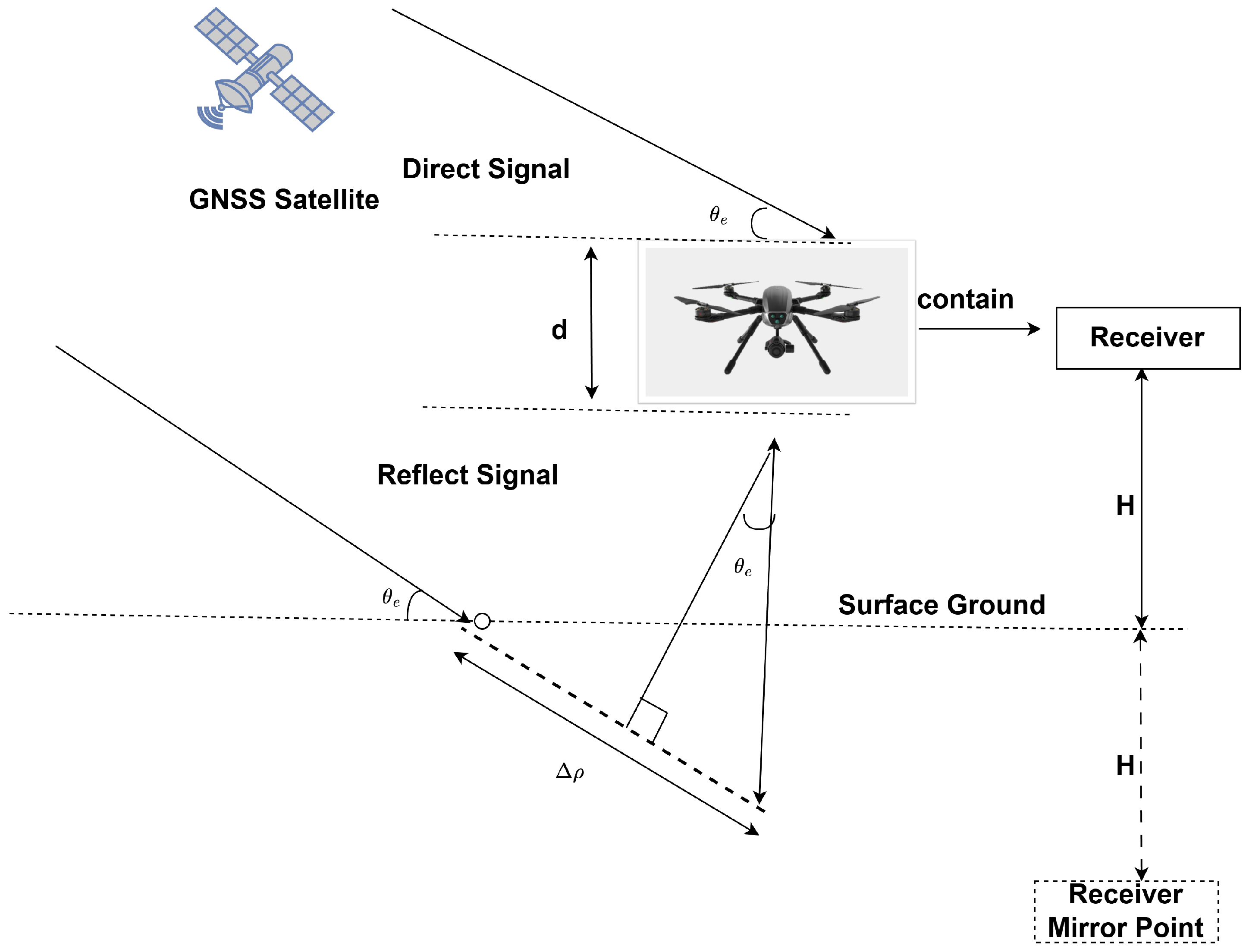
Assuming a flat and horizontal reflecting surface, and given the relative geometry between the UAV and a GNSS satellite, the height of the UAV receiving antenna can be related to the propagation path delay difference between the reflected and direct signals as
H = Δ ρ 2 sin θ e
where θ e denotes the GNSS satellite elevation angle and Δ ρ is the propagation path difference between the reflected and direct signals. The geometry is shown in Figure 1.

2.2. Signal Overlap Effects in Low-Altitude UAV GNSS-R Altimetry

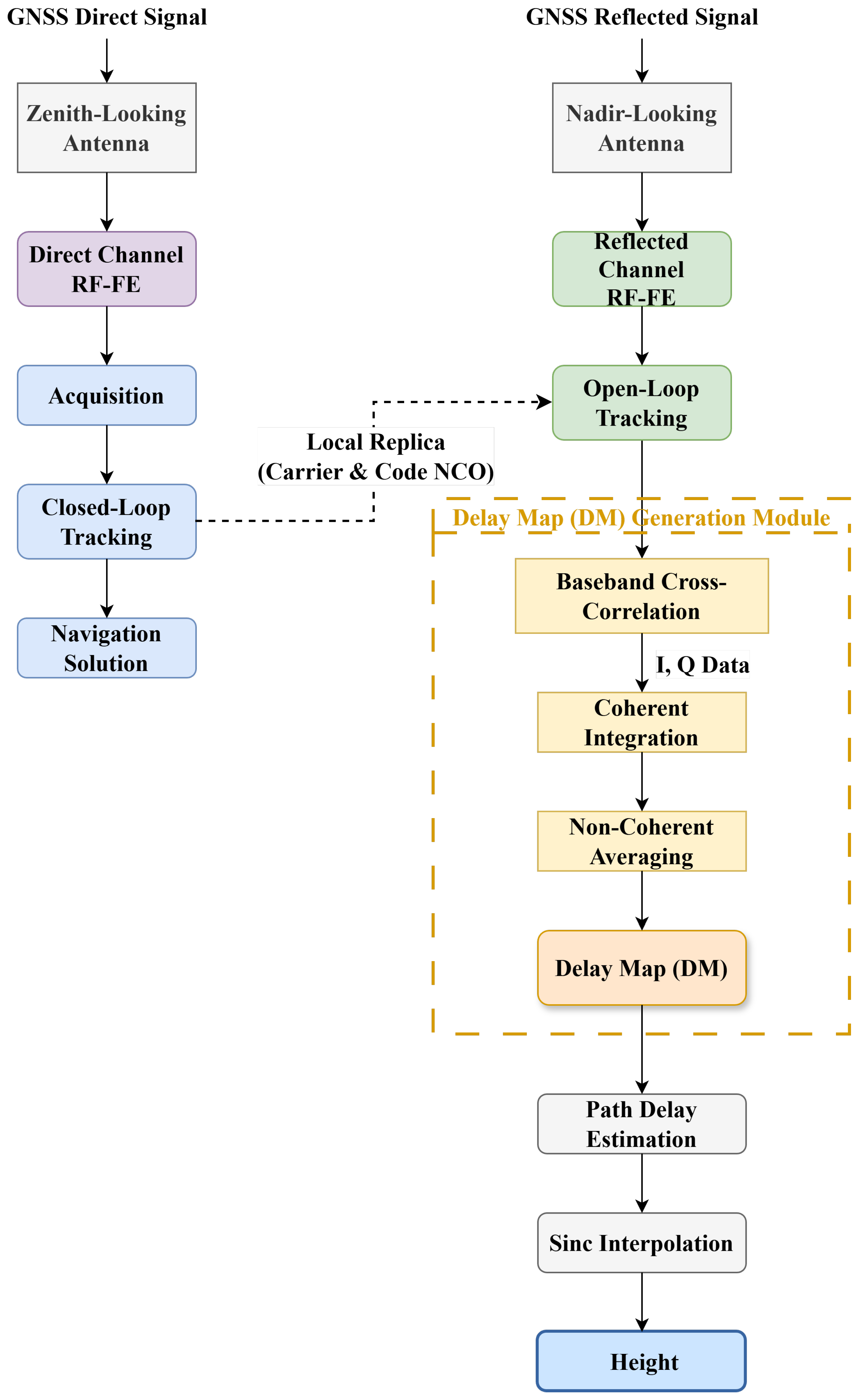
The proposed UAV-based GNSS-R receiver adopts a dual-channel architecture aimed at extracting surface reflection characteristics for remote sensing applications. The receiver simultaneously processes the direct and reflected GNSS signals through two separate channels. Owing to the relatively slow variation of Doppler frequency in airborne platforms, a fixed Doppler assumption is adopted. As a result, a one-dimensional delay-only search is sufficient to generate Delay Maps (DMs). The overall signal processing flow of the proposed receiver, including DM generation and height retrieval, is illustrated in Figure 2.

2.2.1. Intermediate-Frequency Signal Model

The intermediate frequency (IF) signal from the RF front-end is modeled as
r ( t ) = A · C ( t τ ) · D ( t τ ) · cos 2 π ( f c + f d ) t + ϕ + n ( t )
where A is the amplitude, C ( t ) the PRN code, D ( t ) the navigation data, τ the propagation delay, f c the carrier frequency, f d the Doppler shift, ϕ the carrier phase, and n ( t ) additive Gaussian noise.

2.2.2. Delay Map Generation

The received intermediate-frequency (IF) signal r ( t ) is first mixed down to complex baseband to remove the carrier component. The resulting complex baseband signal is expressed as
r b b ( t ) = r ( t ) e j 2 π f c t ,
where f c denotes the carrier frequency. The delay map (DM) is generated by correlating the complex baseband signal r b b ( t ) with a locally generated PRN replica c ( t ) . In practice, the correlation is implemented efficiently in the frequency domain using the Fast Fourier Transform (FFT). The DM is obtained as
R ( τ ) = F 1 F { r b b ( t ) } · C * ( f ) ( τ ) 2 ,
where F { · } and F 1 { · } denote the Fourier transform and inverse Fourier transform, respectively. C ( f ) = F { c ( t ) } represents the Fourier transform of the local PRN code, ( · ) * denotes complex conjugation, and τ is the code delay variable.
The resulting quantity R ( τ ) represents the correlation power as a function of delay and forms the one-dimensional delay map used for subsequent waveform separation and delay estimation.

2.2.3. Signal Overlap in Low-Altitude UAV Scenarios

The received GNSS-R signal y ( t ) in the delay domain can be modeled as the superposition of the direct signal, the reflected signal, their cross-term, and noise:
y ( t ) = y d ( t ) + y r ( t ) + y c ( t ) + n ( t ) ,
where y d ( t ) and y r ( t ) denote the delay-domain responses of the direct and reflected signals, respectively, y c ( t ) represents the cross-correlation term between the direct and reflected signals, and n ( t ) represents additive noise.
In correlation-based GNSS-R receivers, y d ( t ) and y r ( t ) are typically modeled using the autocorrelation function (ACF) of the GNSS spreading code, scaled by their respective amplitudes and delays. However, when the delay separation between the reflected and direct signals becomes small, an additional interference component arises due to the non-orthogonality of overlapping ACF responses.
Δ τ = τ r τ d ,
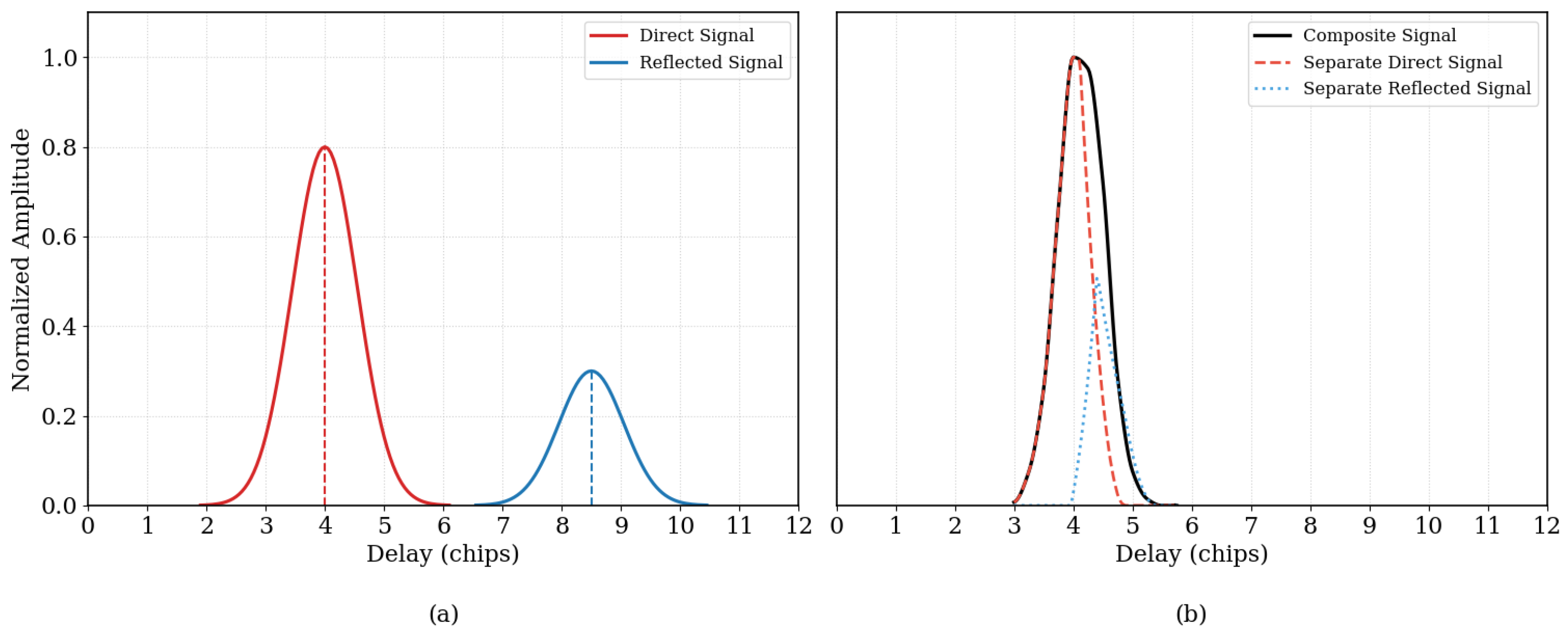
In Figure 3a, at relatively higher flight altitudes the delay-domain responses of the direct and reflected signals are well separated, allowing reliable estimation of the delay difference and subsequent altimetry retrieval. However, in low-altitude UAV scenarios, the relative delay between the reflected and direct signals is typically smaller than one code chip. As a consequence, the delay-domain responses y d ( t ) and y r ( t ) are no longer well separated, and the cross-term y c ( t ) becomes non-negligible. When Δ τ is sufficiently small, the direct and reflected signal components undergo non-orthogonal superposition in the delay domain. In this case, the sidelobes of the strong direct signal, together with the cross-term interference, mask the leading edge of the much weaker reflected signal, causing significant distortion of the composite waveform.
As shown in Figure 3b, which is generated using simulated PRN34 B2a data with a 15 m direct–reflected separation and a 0.25-chip processing resolution, the peak of the composite correlation response no longer corresponds to the true delay of either y d ( t ) or y r ( t ) . Instead, its location is shifted due to the combined effects of signal overlap and cross-correlation interference. Consequently, conventional peak-detection-based delay estimation methods become unreliable, leading to biased delay estimation and erroneous height retrieval.
Due to this signal overlap, direct signal interference (DSI) and cross-term distortion can significantly affect the observation, making the separation of the reflected signal y r ( t ) from the stronger direct signal y d ( t ) challenging. Therefore, appropriate signal separation or interference mitigation strategies are required, which will be discussed in the following section.

2.3. Proposed Adaptive Interference Mitigation Framework

To mitigate the severe direct signal interference (DSI) encountered in low-altitude UAV-based GNSS-R altimetry, we develop an adaptive processing framework based on delay-domain waveform decomposition. In low-altitude scenarios, the path-length difference between the direct and reflected signals is typically much smaller than one GNSS code chip, which causes strong temporal overlap in the delay domain. Moreover, the direct component often dominates the reflected component ( A d A r ), so naive cancellation is highly sensitive to amplitude overestimation and may produce non-physical negative residual power. To address these challenges, we adopt a cascaded scheme consisting of (i) shape-preserving interpolation in the delay domain, (ii) robust estimation of direct-signal parameters, and (iii) adaptive mitigation with a non-negativity constraint followed by residual-based reflection scanning. This strategy enables stable delay separation and height retrieval without requiring explicit multipath priors.

2.3.1. Observation Model with Coherent Cross Term

Let the complex delay-domain correlation outputs of the direct and reflected signals be denoted by d ( τ ) and r ( τ ) , respectively. For a power waveform formed as I 2 + Q 2 = | · | 2 , the observed delay waveform can be written as
y ( τ ) = B + d ( τ ) + r ( τ ) 2 ,
where B is the background power floor. Expanding (7) yield
y ( τ ) = B + | d ( τ ) | 2 + | r ( τ ) | 2 + 2 d ( τ ) r * ( τ ) .
Using an amplitude-domain spreading-code autocorrelation template g ( · ) , we model
d ( τ ) = A d g ( τ τ d ) e j ϕ d , r ( τ ) = A r g ( τ τ r ) e j ϕ r ,
where A d 0 and A r 0 are power-domain scaling factors, and τ d , τ r are the corresponding delays. Substituting (9) into (8) gives the power-domain form
y ( τ ) = B + A d g d 2 ( τ ) + A r g r 2 ( τ ) + z g d ( τ ) g r ( τ ) ,
where g d ( τ ) = g ( τ τ d ) , g r ( τ ) = g ( τ τ r ) , and the coherent cross-term coefficient
z = 2 A d A r cos ( Δ ϕ ) , Δ ϕ = ϕ d ϕ r .
In low-altitude strong-overlap conditions, the cross term in (10) can produce a pedestal bias in the main-lobe region, making direct subtraction prone to over-cancellation and negative residual artifacts.

2.3.2. Robust Direct Estimation and Non-Negativity-Constrained Mitigation

Each observed delay map (DM) waveform is initially sampled on a discrete 12-bin delay axis. To increase the effective delay resolution while avoiding oscillatory artifacts, we upsample the waveform using a shape-preserving piecewise cubic Hermite interpolating polynomial (PCHIP), yielding an interpolated power waveform y ( τ ) on a finer delay grid.
The background power floor is estimated as the median of samples sufficiently far from the direct-signal main lobe:
B ^ = median { y ( τ ) : | τ τ d | τ guard } .
To robustly estimate the direct-signal power scale while reducing contamination from reflected energy and the cross-term pedestal, only the descending slope (right half) of the direct main lobe is utilized. This design is motivated by the limited length of the correlation delay window in the miniaturized receiver, which frequently truncates the left portion of the direct peak and makes reliable amplitude estimation based on that region difficult.
Let R 2 ( · ) denote the squared autocorrelation template (ACF2) constructed from the corresponding PRN code. We define
Γ ( τ ) = y ( τ ) B ^ R 2 ( τ τ d ) , τ Ω d + ,
where Ω d + denotes the descending side of the direct main lobe. The evaluated ratio can be modeled as
Γ ( τ ) = A d + ϵ ( τ ) + δ ( τ ) ,
where A d denotes the true direct-signal amplitude, ϵ ( τ ) is zero-mean background noise, and δ ( τ ) represents additional contributions from reflected energy and cross-term interference. Although the coherent cross term may locally introduce either positive or negative fluctuations depending on the phase difference Δ Φ , the dominant disturbance in the descending-lobe region typically manifests as upward deviations caused by the reflected-energy component. Therefore, applying a lower-quantile estimator, which extracts the lower-tail statistics of Γ ( τ ) , effectively bypasses these upward deviations. Accordingly, the direct amplitude estimate is obtained as
A ^ d = Q q Γ ( τ ) , q ( 0 , 0.5 ) ,
which provides a robust estimate of the baseline direct-signal amplitude.
Rather than subtracting B ^ + A ^ d R 2 ( τ τ d ) directly (which may violate the physical constraint of non-negative power), we apply an adaptive clipping operation:
y ^ d ( 0 ) ( τ ) = B ^ + A ^ d R 2 ( τ τ d ) ,
y ^ d ( τ ) = min y ( τ ) , y ^ d ( 0 ) ( τ ) ,
y res ( τ ) = y ( τ ) y ^ d ( τ ) 0 .
This pointwise clipping prevents over-subtraction within the overlapped main-lobe region and guarantees a physically admissible (non-negative) residual waveform. Importantly, the coherent cross term in (10) is not explicitly estimated; instead, its impact is treated as a structured disturbance that is suppressed by the robust quantile estimate (15) and the non-negativity constraint (17) and (18).

2.3.3. Residual-Based Reflection Scanning and Delay Offset Estimation

After mitigation, the residual waveform contains the dominant reflected component along with background and unmodeled disturbances (including any remaining cross-term effects). We estimate the reflected delay offset Δ τ = τ r τ d by scanning candidate offsets and fitting a scaled ACF2 template to the residual:
y ^ r ( τ ; Δ τ ) = A r R 2 ( τ τ d Δ τ ) .
For each candidate Δ τ , the amplitude A r is obtained by a non-negative least-squares projection over a local window Ω r around the hypothesized reflection peak:
A r ( Δ τ ) = arg min A r 0 τ Ω r y res ( τ ) A r R 2 ( τ τ d Δ τ ) 2 .
The optimal delay offset is selected by minimizing the mean squared error over a predefined fitting region Ω fit :
Δ τ ^ = arg min Δ τ 1 | Ω fit | τ Ω fit y res ( τ ) y ^ r ( τ ; Δ τ ) 2 .
The resulting Δ τ ^ is converted to a path-length difference and used for height retrieval.

2.3.4. Height Retrieval

Given the estimated delay offset Δ τ ^ , the UAV height is obtained from the geometric relationship
H = c Δ τ ^ 2 sin θ e ,
where c is the speed of light and θ e is the satellite elevation angle.

3. Experiment and Setup

Simulation Tools and the Receiver

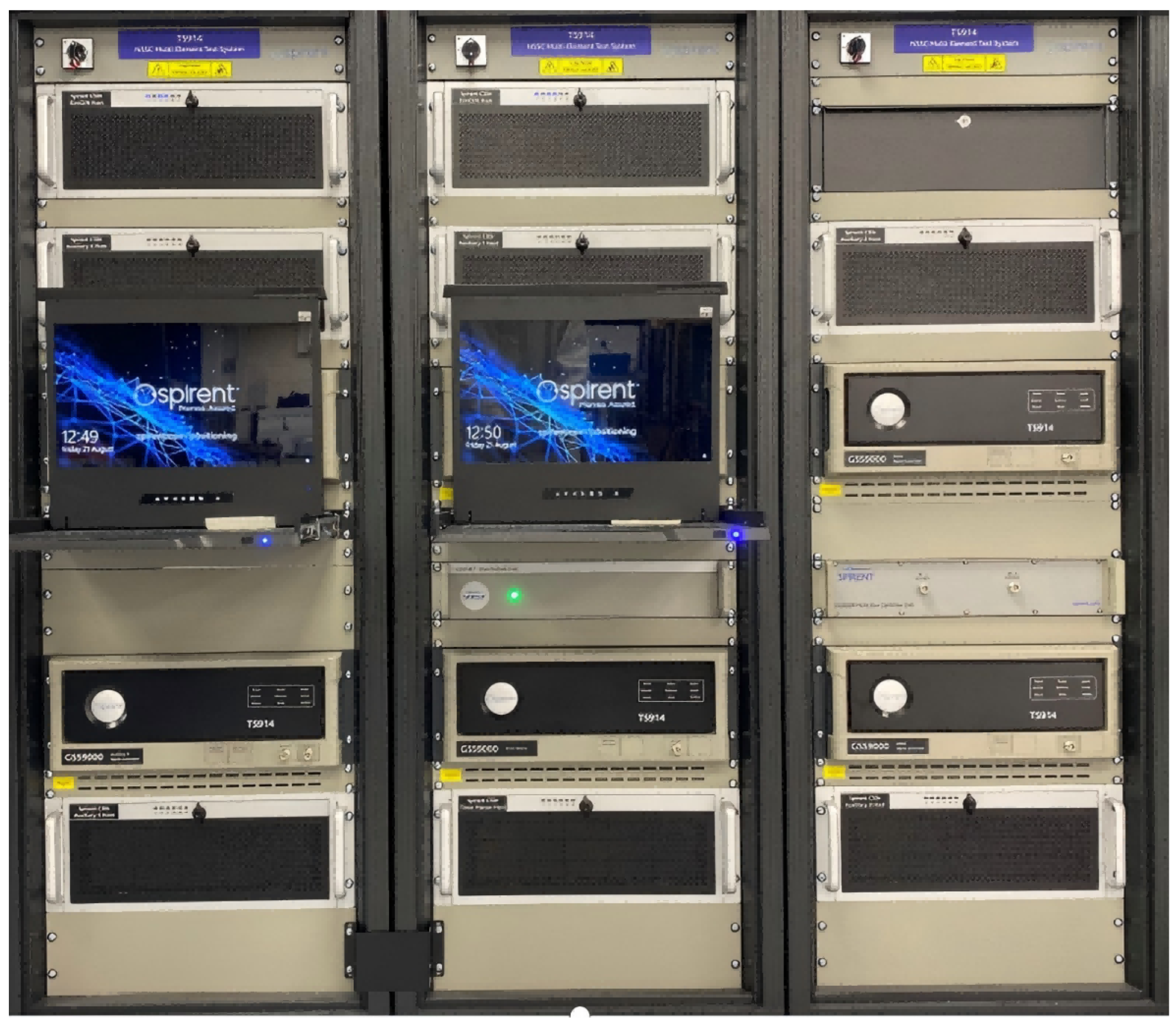
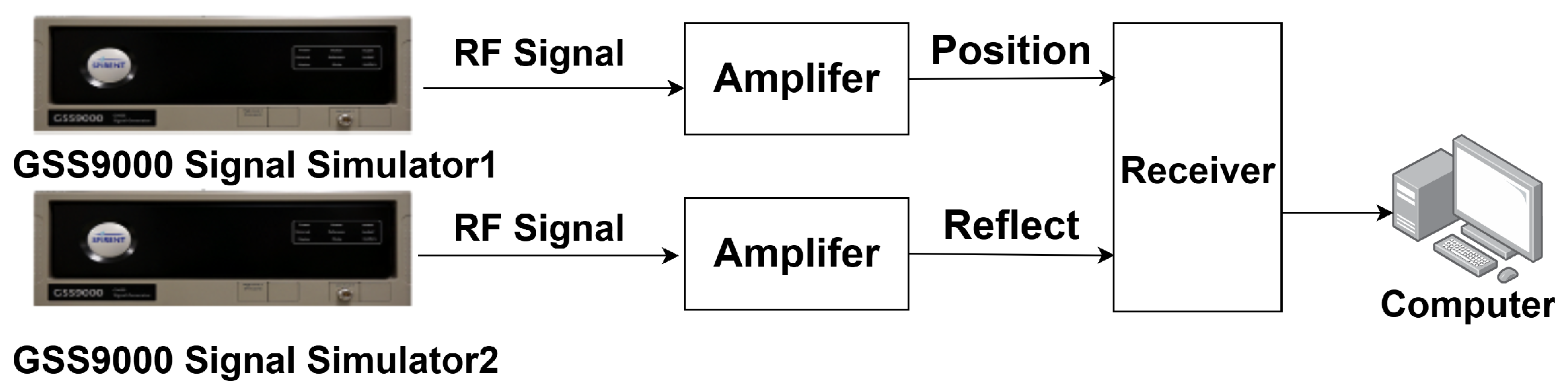
This study employs the Spirent GSS-9000 multi-frequency GNSS signal simulator as the primary signal source. The test setup incorporates five GSS-9000 units capable of generating signals for multiple constellations, including GPS, BeiDou-2/3, Galileo, and GLONASS. The system supports both single-carrier multi-antenna and multi-carrier single-antenna configurations. In the simulation, two synchronized GNSS simulators are employed: one generates direct positioning signals, while the other emulates the corresponding reflected signals. The hardware layout and signal connection diagram are illustrated in Figure 4 and Figure 5.
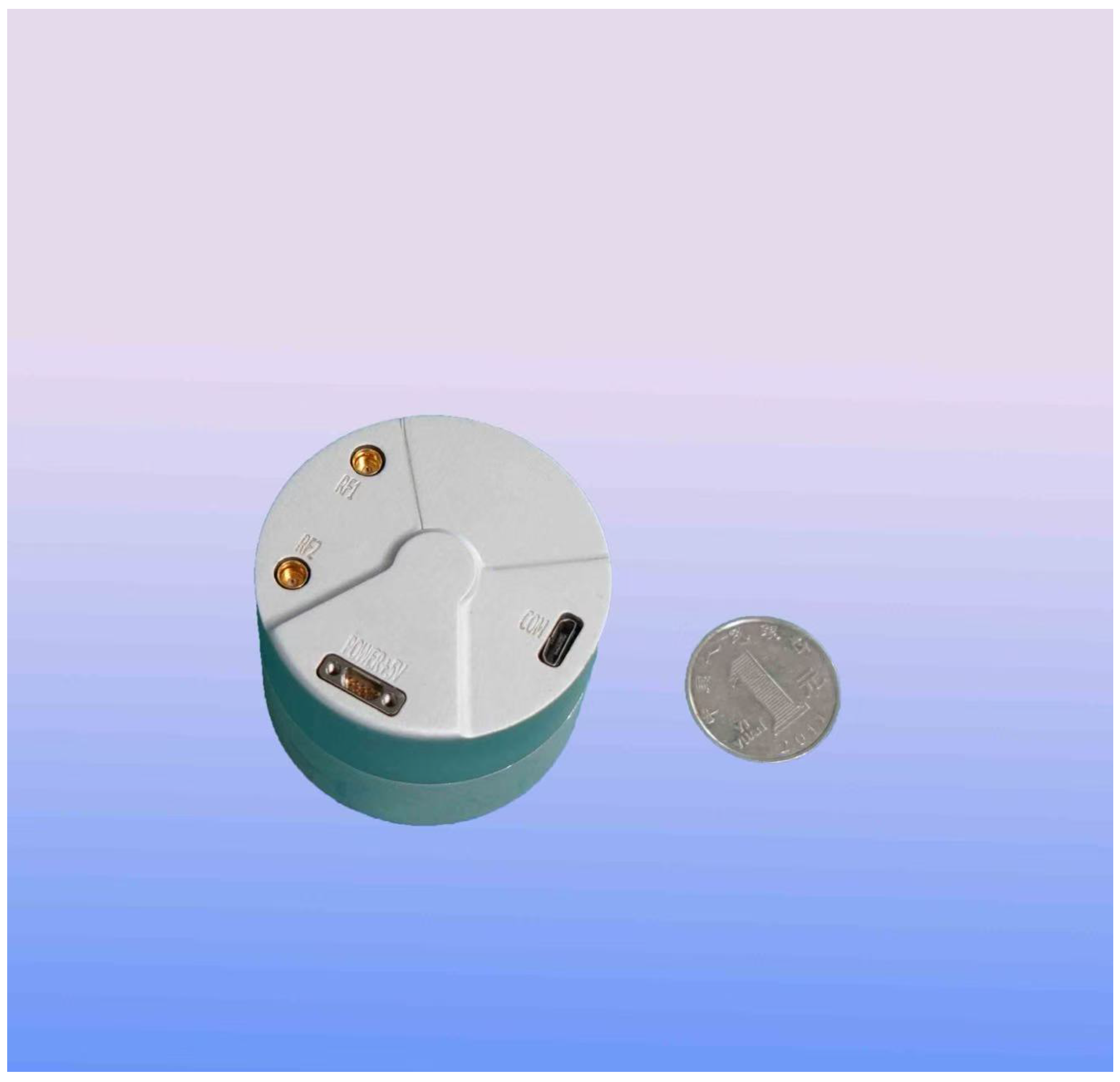
To enable real-time GNSS-R altimetry, we developed a compact, low-power receiver specifically designed for UAV platforms. As detailed in Table 2, the receiver is based on a Xilinx Zynq-7020 SoC (Xilinx Inc., San Jose, CA, USA) and operates with a 40 MHz reference oscillator. It adopts a cylindrical design, measuring 49.22 mm in diameter and 39.95 mm in height. Figure 6 presents the receiver next to a coin for scale, highlighting its compactness and suitability for UAV platforms.
The system supports BeiDou B1C and B2a signals. The B1C signal has a bandwidth of 4.092 MHz, whereas B2a provides a wider 20.46 MHz bandwidth, enabling finer delay resolution for reflected signal processing. To ensure accurate reconstruction of the signal envelope and delay estimation, the receiver employs a 22 MHz intermediate-frequency (IF) filter and samples the incoming signals at 80 MHz. The total power consumption is 4.895 W under standard conditions (25 °C).

4. Results

4.1. Effects of Different Correlation Resolutions on Height Retrieval Performance

The capability of the proposed algorithm in separating mixed direct and reflected signals under low-altitude conditions was examined via a Monte Carlo simulation. The main simulation parameters are summarized in Table 3. Multiple realizations of noisy echo waveforms were generated to statistically assess height retrieval performance under different correlation sampling resolutions.
The BeiDou B2a PRN sequences (PRN 1–63) were employed to construct ideal autocorrelation functions, based on which composite waveforms consisting of direct, reflected, and noise components were synthesized. Correlation outputs were simulated at different sampling resolutions, and the true direct-path delay was used as a temporal reference for performance evaluation.
The separation performance was evaluated by varying the prescribed path-length gap between the reflected and direct signals. For each realization, the direct–reflected delay difference was estimated using the proposed algorithm and converted into height. The BeiDou B2a signal was investigated under three correlation sampling resolutions: 1 chip, 0.5 chip, and 0.25 chip.
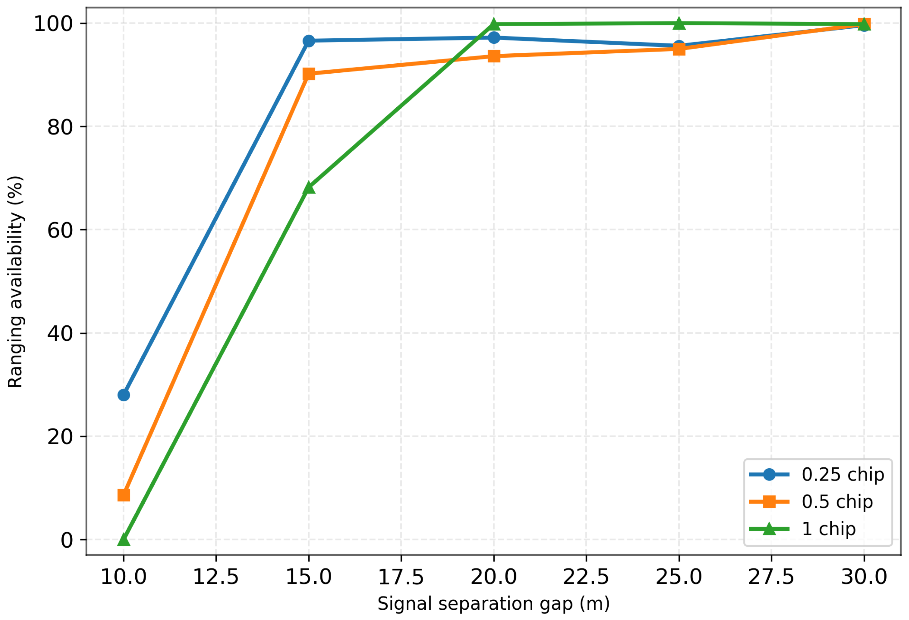
Figure 7 illustrates the statistical detection success probability as a function of the delay separation between the direct and reflected signals under three correlation sampling resolutions (0.25, 0.5, and 1 chip). The detection success probability is defined as the probability that the reflected signal can be successfully separated and yield a valid ranging estimate. Overall, for all resolution settings, the detection success probability generally increases as the delay separation between the signals becomes larger.
In the small-separation regime, the performance differences among the correlation resolutions become particularly pronounced. When the equivalent height separation corresponding to the direct–reflected path difference is approximately 10 m, the detection success probability drops significantly for all resolutions. Under this condition, reliable signal separation is nearly unattainable for the 0.5-chip and 1-chip resolutions, whereas the 0.25-chip resolution still maintains a certain level of detection success probability. This result indicates that a finer correlation sampling resolution improves the capability to resolve closely spaced signal components in the delay domain, thereby mitigating the performance degradation caused by waveform overlap.
When the delay separation exceeds a certain threshold, the detection success probability for all three resolutions approaches 100%, indicating that reliable signal separation can be achieved once waveform overlap becomes sufficiently reduced. It is worth noting that under the 1-chip resolution, fluctuations can still be observed when the equivalent height separation exceeds approximately 15 m. These variations are mainly attributed to increased delay estimation errors introduced by the coarse correlation sampling resolution, which reduces the statistical stability of the ranging results.
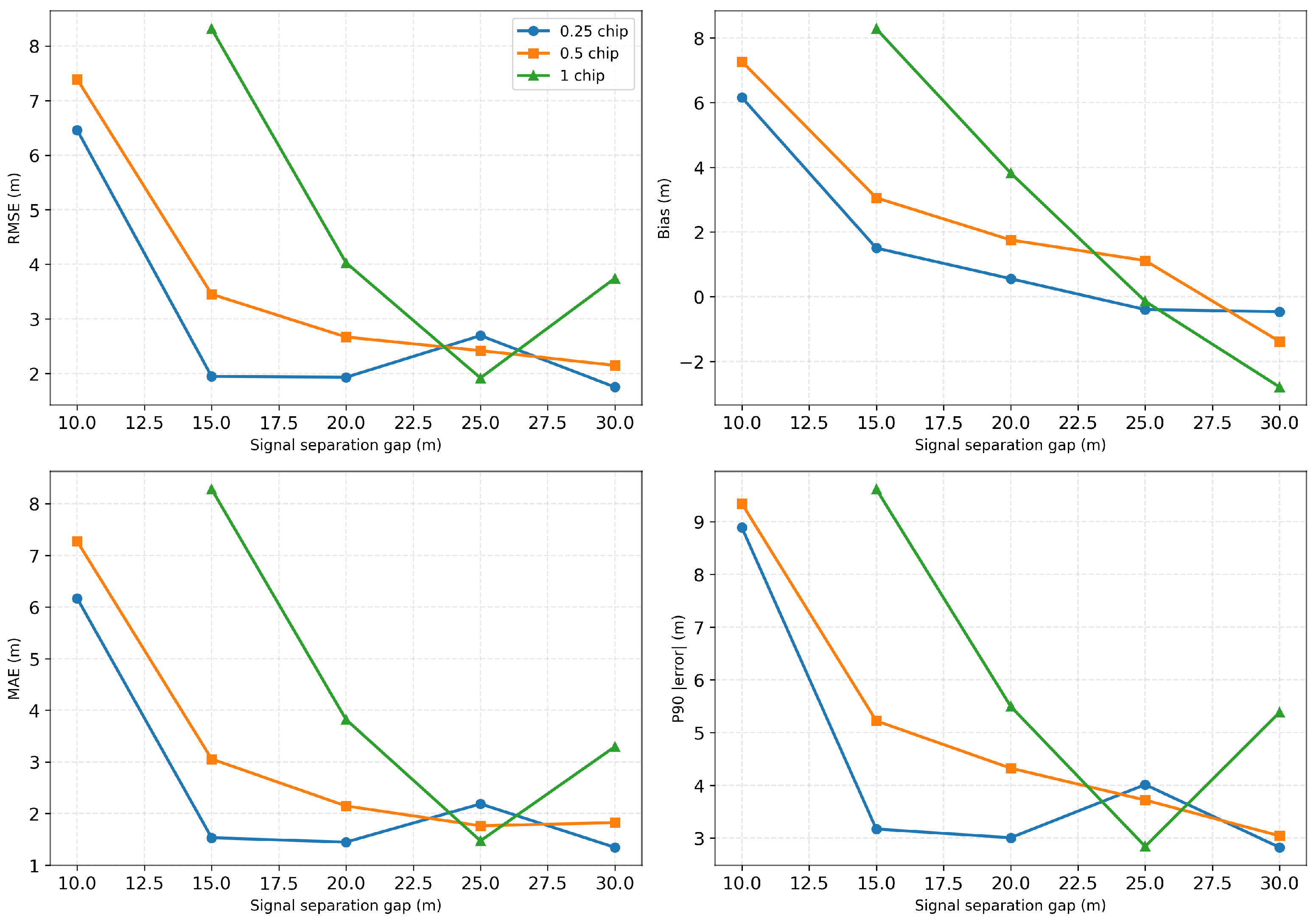
Further analysis of the estimation errors is presented in Figure 8. To provide a more comprehensive evaluation of the algorithm performance, the statistical assessment is extended beyond the conventional root-mean-square error (RMSE) metric by incorporating additional indicators, including the mean error (Bias), standard deviation (Std), and the 90th percentile error (P90). The Bias reflects the systematic offset of the estimation results, the Std characterizes the random variability of the errors, and the P90 metric describes the upper-bound behavior of the error distribution. Together, these indicators provide a more complete characterization of the robustness of the proposed algorithm under different signal overlap conditions. The detailed statistical results are summarized in Table 4.
From these statistical metrics, it can be observed that the 0.25-chip resolution achieves the best overall performance among the three correlation resolutions. As the delay separation (gap) between the direct and reflected signals increases, the degree of waveform overlap gradually decreases, and all error metrics show noticeable improvements. This indicates that both the signal separation capability and the ranging accuracy improve as the signals become more separable. The 0.5-chip resolution exhibits a similar trend, with the error metrics gradually decreasing as the gap increases.
In contrast, under the 1-chip resolution, a degradation in estimation accuracy can be observed when the gap exceeds approximately 25 m. This phenomenon is mainly caused by the inherent limitation introduced by the coarse correlation sampling resolution. Since one chip corresponds to approximately 29.3 m in code length, when the true delay separation is smaller than or comparable to this sampling scale, the discretization of the correlation peak may introduce non-negligible estimation errors, thereby affecting the stability and accuracy of the delay estimation. Consequently, under coarse-resolution conditions, the statistical performance may still be constrained by the sampling resolution even when the signal separation becomes larger.

4.2. Performance Evaluation Under Varying Reflected-to-Direct Signal Ratios

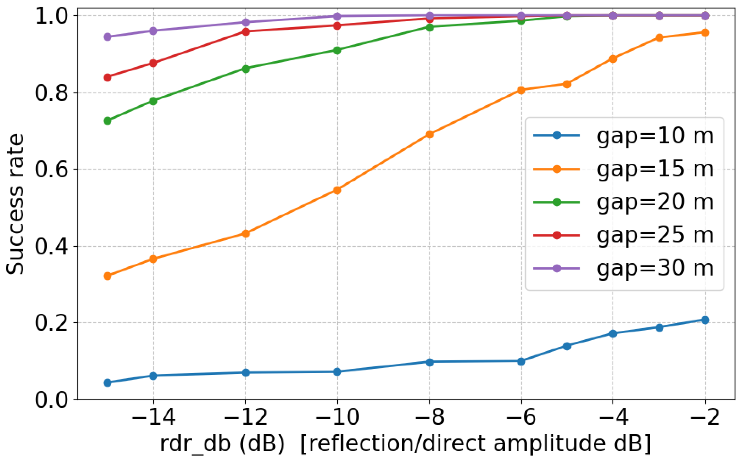
A simulation-based Monte Carlo experiment was conducted to assess the impact of reflected-signal strength on the detection performance of the reflected component and the accuracy of height (delay-gap) estimation. In the experiment, the equivalent amplitude of the direct component was fixed at A d = 1 , and the equivalent signal-to-noise ratio (SNR) in the correlation-waveform domain was maintained at 20 dB. The reflected-signal strength was varied by sweeping the reflected-to-direct amplitude ratio (RDR, in dB). The main simulation parameters are summarized in Table 5.
In addition, multiple direct–reflected delay separations, corresponding to path-length gaps ranging from 10 to 30 m, were considered to analyze the influence of signal overlap on the separation performance.
For each parameter configuration, N Monte Carlo trials were performed ( N = 500 in this study). The reflected-signal detection success rate, and the ranging root-mean-square error (RMSE) were computed.
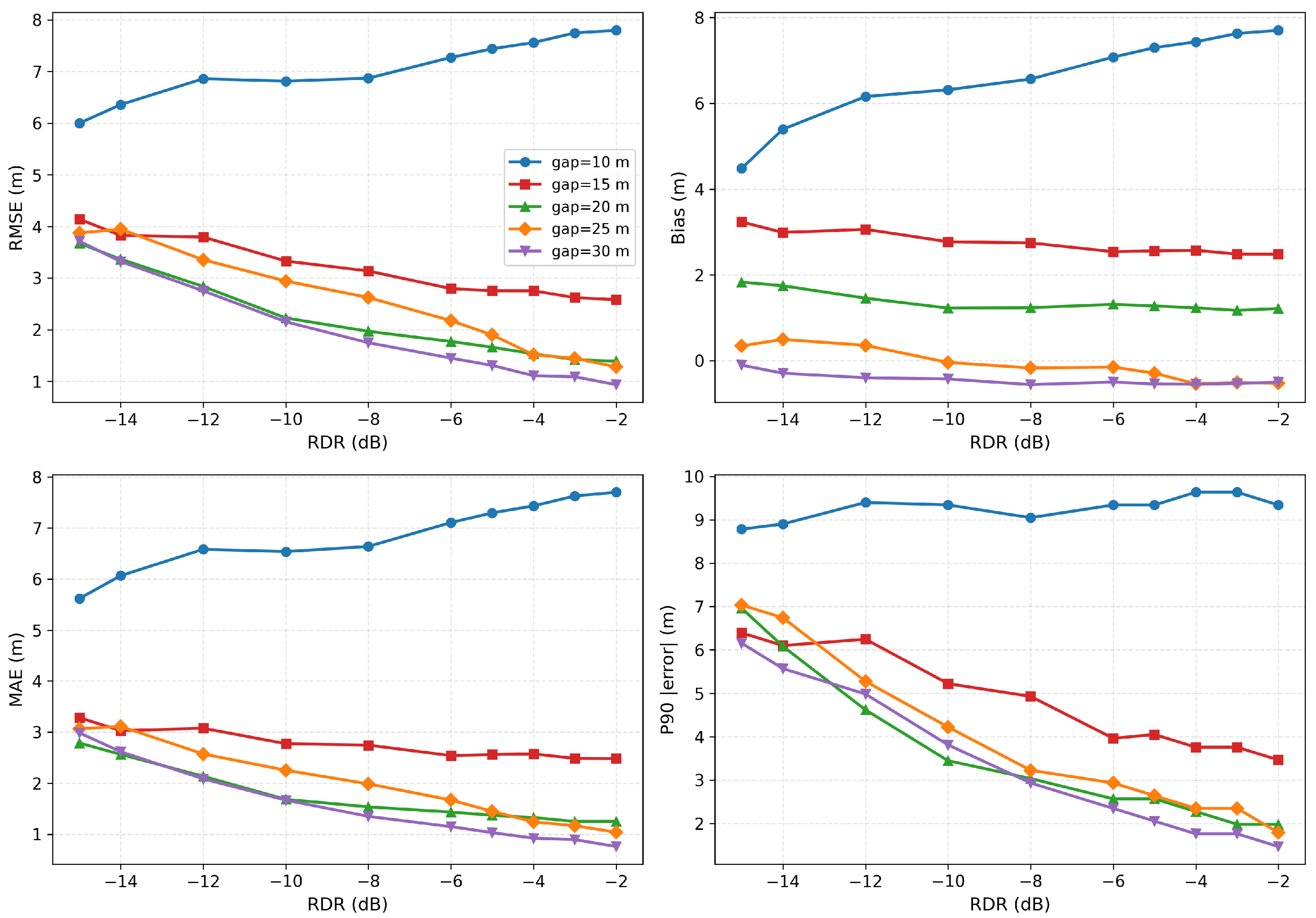
Figure 9 and Figure 10 summarize the influence of reflected-signal strength on detection performance and ranging accuracy under different direct–reflected delay separations. In addition to the root mean square error (RMSE), the figures also present several statistical evaluation metrics, including the mean error (Bias), standard deviation (Std), and the 90th percentile error (P90), which provide a comprehensive characterization of the ranging error from different statistical perspectives. With the SNR fixed at 20 dB, both the detection success rate and the ranging accuracy generally improve as the reflected-to-direct amplitude ratio increases, and the different statistical metrics exhibit consistent trends.
A notable exception occurs when the equivalent height gap is 10 m. Under this condition, regardless of the reflected-signal strength, the detection success rate as well as all error-related metrics remain significantly inferior to those obtained at larger delay separations. This behavior is consistent with the analysis presented in the previous subsection and can be attributed to severe delay-domain overlap between the direct and reflected signals.
More specifically, when the delay separation is small (corresponding to the 10 m height gap), the correlation responses of the direct and reflected signals become highly correlated, making the separation problem ill-conditioned. Under this strong overlap condition, the composite correlation waveform contains not only the individual signal components but also significant cross-interference terms between them. These cross terms scale with the product of the amplitudes of the direct and reflected signals and, therefore, become more pronounced as the reflected-signal strength increases. Consequently, increasing the reflected-signal strength does not simply improve detectability. Instead, the enhanced cross-interference distorts the symmetry of the composite main lobe and shifts the effective peak location away from the true delay of the direct signal, introducing additional bias in the delay estimation and leading to larger ranging errors under strong overlap conditions. This effect is reflected not only in the RMSE but also consistently in the Bias, Std, and P90 metrics.
Therefore, such strong waveform superposition limits the effective separability of the two signals, thereby constraining both detection reliability and ranging performance. The degradation under this height-gap condition is also clearly reflected in the quantitative results reported in Table 6 and Table 7.
For delay separations larger than 10 m, the detection success rate increases monotonically with the reflected-signal strength and approaches unity once the reflected component becomes sufficiently strong. Meanwhile, all error-related statistical metrics improve significantly. As illustrated in Figure 10, the RMSE, Bias, Std, and P90 all decrease as the reflected-signal strength increases. These results indicate that, outside the regime dominated by strong signal overlap, the reflected-signal strength becomes the primary factor governing the achievable ranging accuracy.
Overall, the results demonstrate that the proposed algorithm can effectively separate the mixed direct and reflected signals. Under favorable delay separation and signal-strength conditions, all statistical metrics remain stable, and the ranging accuracy can reach sub-meter levels, with errors below 1 m.

4.3. Flight-Scenario Simulation Validation Using the SPIRENT 9000 Platform

Evaluation of the proposed algorithm under conditions representative of real flight operations was performed by integrating the algorithm into the ARM processor of the self-developed receiver. Experimental scenarios were constructed within the SPIRENT 9000 flight scenario simulator, with testing conducted based on realistic flight geometries. The simulator generates composite signals consisting of direct and reflected components according to true geometric configurations and temporal dynamics, thereby enabling effective emulation of GNSS signal propagation and reflection effects in low-altitude flight environments. Compared with Monte Carlo simulations relying on idealized signal models, this experimental environment more faithfully captures key characteristics, including time-varying path delays, dynamic platform height variations, and the evolution of correlation peak shapes.
Algorithm validation was carried out using a miniaturized self-developed receiver platform, where the proposed algorithm was implemented on the ARM processor of the receiver for real-time signal processing, allowing system-level assessment under conditions closely aligned with practical engineering implementation. This configuration facilitates observation of waveform superposition phenomena and their dynamic behavior within realistic receiver processing chains in low-altitude flight scenarios.
To construct a physically consistent simulation environment, the GNSS-R observation geometry was explicitly modeled within the SPIRENT simulator. Satellite positions were obtained from precise ephemeris data, while the UAV receiver trajectory and motion parameters were predefined to emulate realistic low-altitude flight operations. Based on the transmitter (satellite) and receiver (UAV) positions, the bistatic reflection geometry was established and the specular reflection point was determined accordingly. The corresponding path difference between the direct and reflected signals was computed according to the bistatic geometry model, which directly determined the delay separation between the two signal components. The reflected signal power was also generated based on geometry-dependent propagation conditions.
Within the SPIRENT 9000 simulation environment, three correlation processing resolutions were configured at the receiver ARM processor: 0.25 chip, 0.5 chip, and 1 chip. The simulator produced 12-level DM waveforms for processing. In addition, multiple direct–reflection path separation scenarios were established through the introduction of varying relative delays applied to the reflected signals. Under dynamic conditions, the detection and tracking capabilities of the algorithm with respect to reflected signals were evaluated through analysis of correlation peak separation and their temporal evolution. Ranging accuracy was further examined through quantitative analysis.
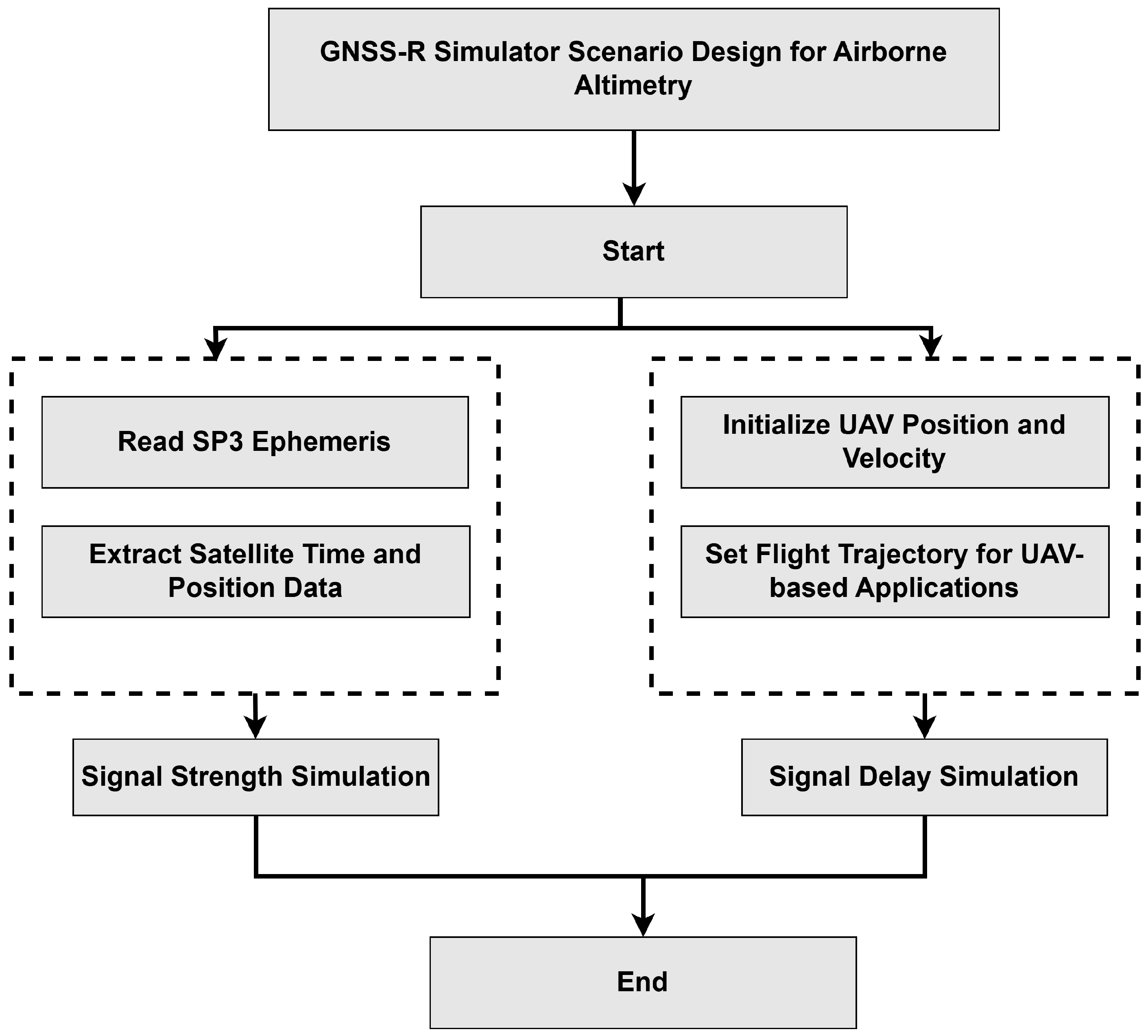
For the establishment of standardized and repeatable comparative experiments, benchmark test scenarios were generated via automated inputs driven by the UCD (User Command Definition) command set, as shown in Figure 11. The UCD command set represents a structured command mechanism designed for describing simulator scenario configurations and signal generation control parameters. Unified definitions of platform motion states, signal propagation conditions, and multipath parameters ensure consistency and reproducibility across different experimental settings. Representative path separations of 10 m, 15 m, and 30 m were selected. Systematic evaluation of signal separation performance under varying correlation resolutions and delay conditions was achieved through comparison between simulator outputs and corresponding benchmark configurations. The operational range and performance limits of the proposed method under realistic flight scenarios were also analyzed.
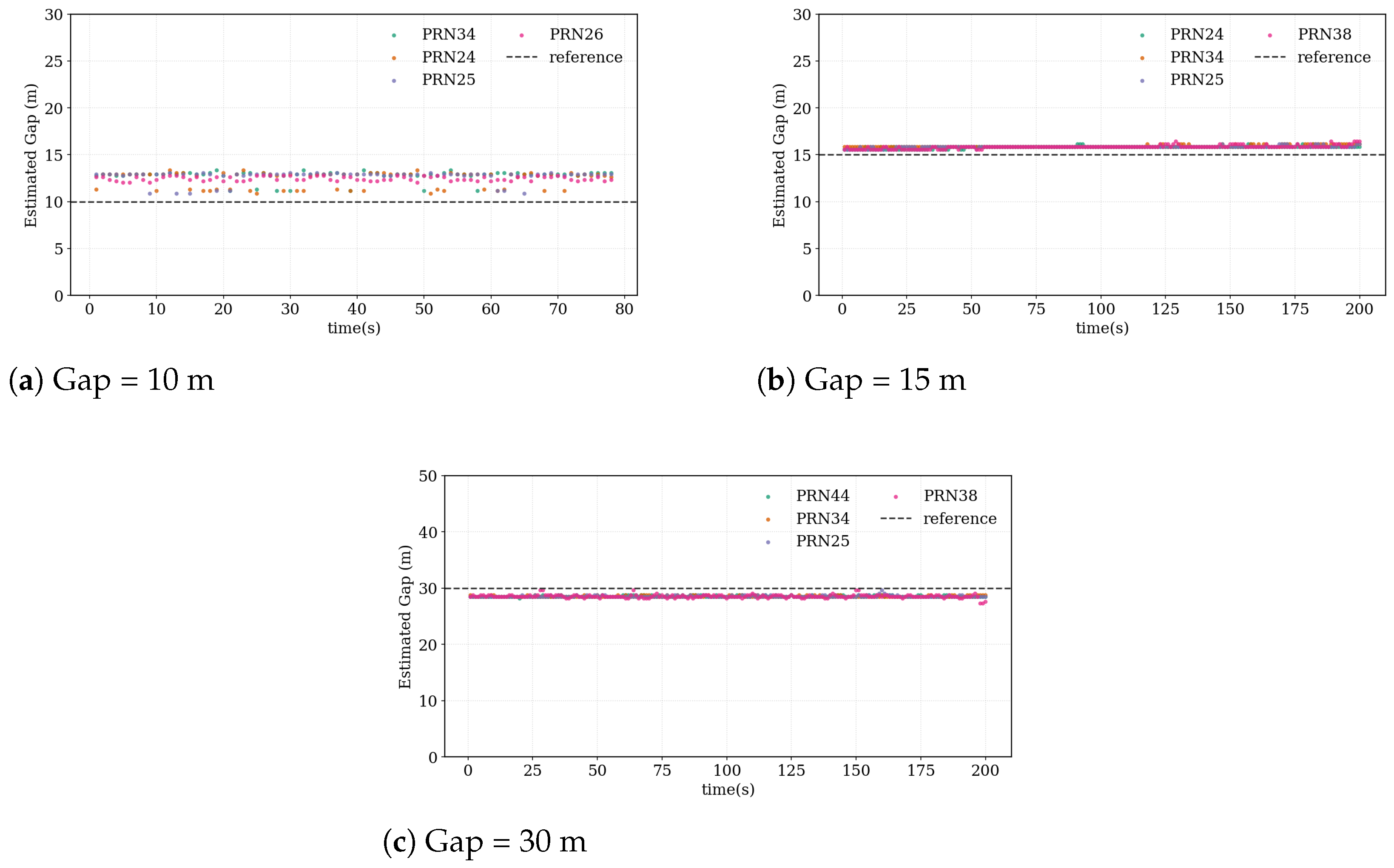
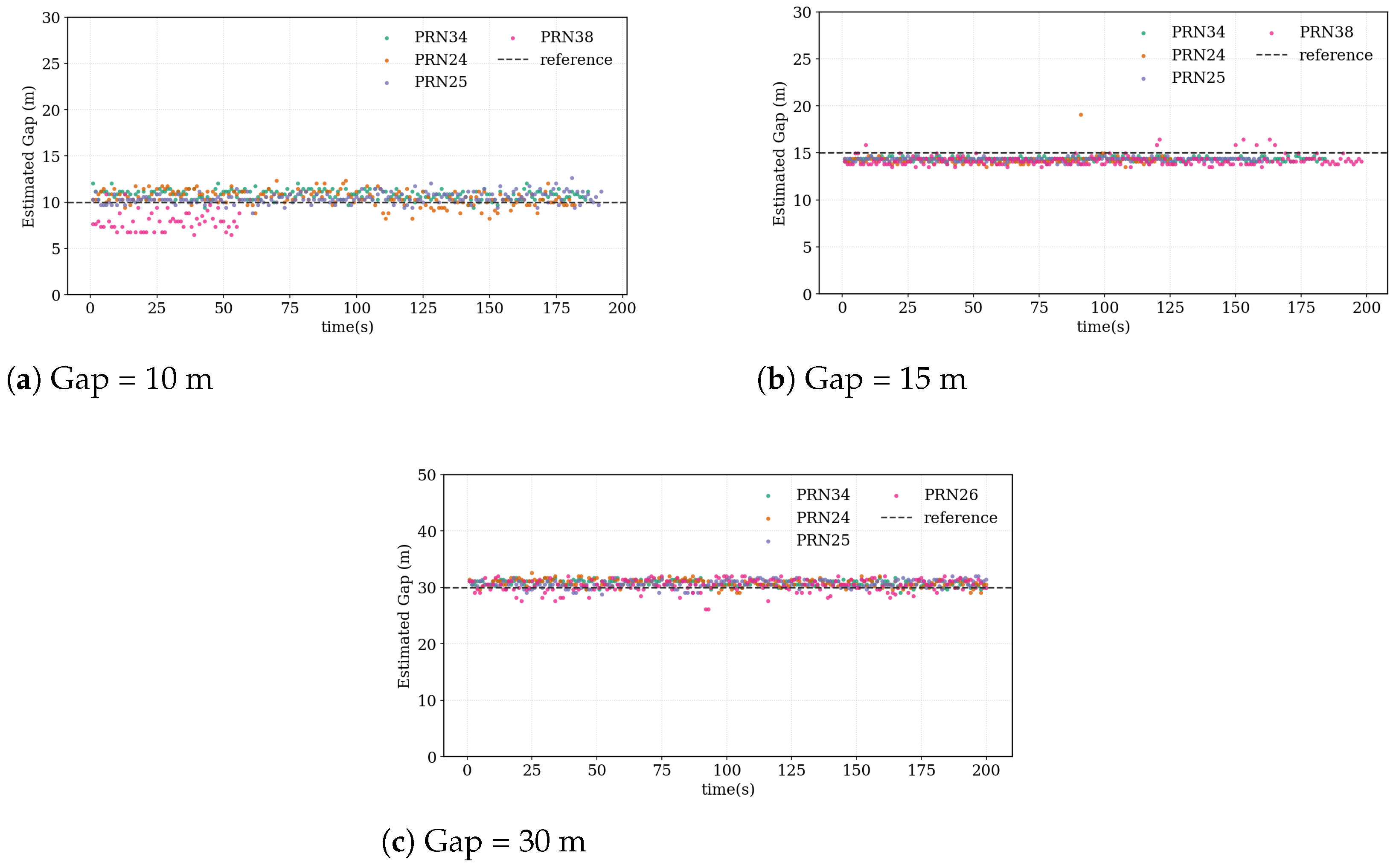
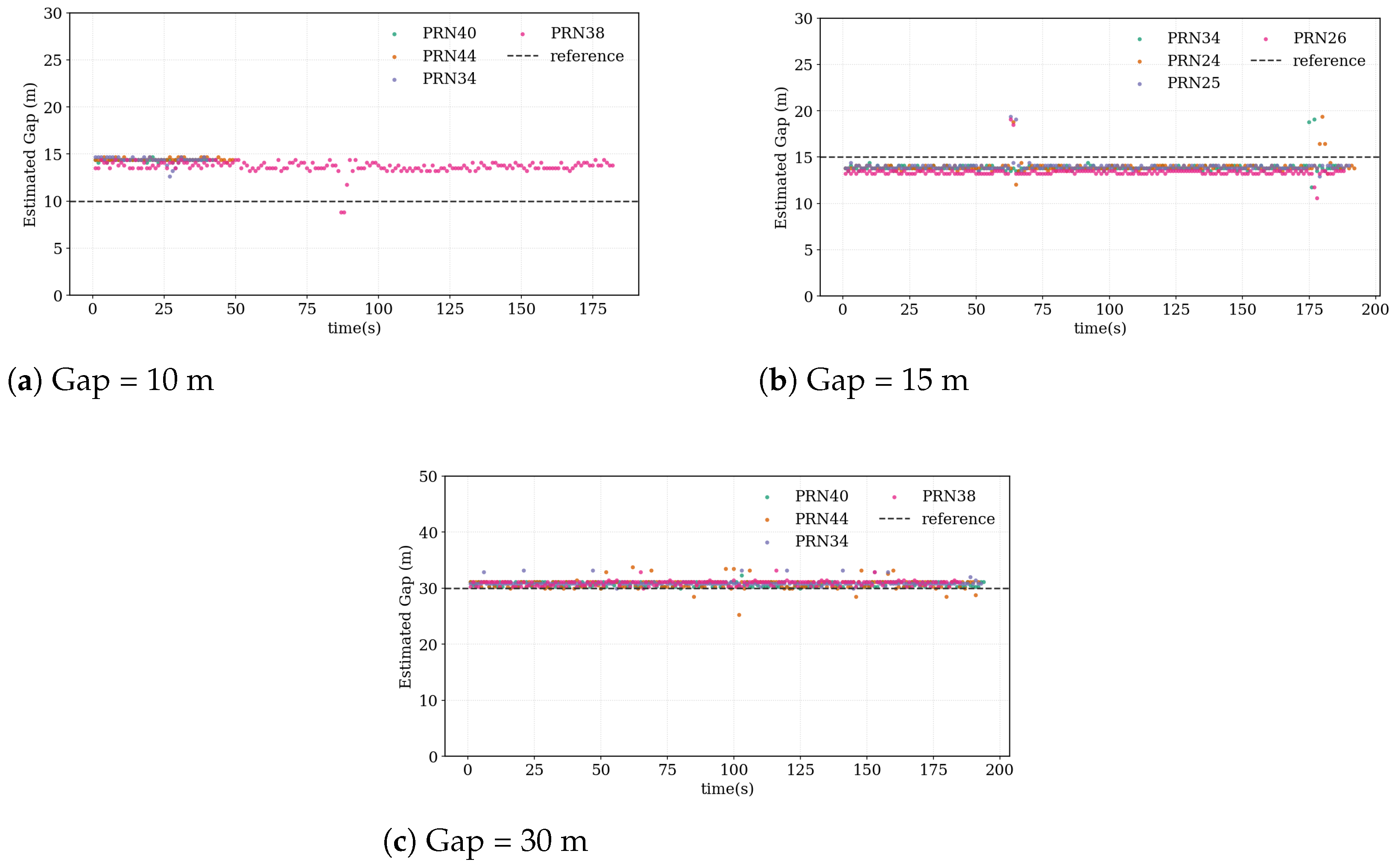
Figure 12, Figure 13 and Figure 14 illustrate the estimated direct–reflection path separations obtained during flight scenario simulations when the platform traversed approximately 10 m along its trajectory. Results are presented for correlation resolutions of 0.25 chip, 0.5 chip, and 1 chip. Colored scatter points denote estimates from different PRN satellites, while dashed lines indicate reference path separations. Due to hardware processing constraints of the receiver, only the four satellites with the highest elevation angles were included. Major error sources were analyzed previously, and real-time correction strategies were incorporated within the receiver processing chain. System-level errors introduced by the simulator were calibrated and compensated. Consequently, the reported results primarily reflect the intrinsic performance of the proposed algorithm.
Overall, under dynamic flight conditions, effective detection and separation of reflected signals were achieved across all three correlation resolutions. The estimated path separations from different PRN satellites are generally distributed around the reference values, indicating that the proposed algorithm maintains reliable performance under realistic flight geometries and platform motion dynamics.
Clear performance differences can nevertheless be observed among the three correlation resolutions. Under the 1 chip resolution, the estimates exhibit significant dispersion, with certain PRNs showing consistent deviations relative to the reference values, suggesting the presence of systematic bias.
It should be noted that this bias mainly originates from the coarse discretization of the correlation waveform rather than an intrinsic limitation of the proposed signal separation method. For example, a 10 m path-length gap is observed on a sampling grid with a chip length of approximately 29.3 m. In such cases, when the true path-length gap is smaller than the effective sampling interval, the discretized correlation waveform may introduce a deterministic offset in the estimated peak location. This behavior is mainly attributed to the broader correlation peaks associated with coarse-resolution processing. Although interpolation techniques were applied, the limited effective resolution still introduces non-negligible estimation errors.
When the resolution improves to 0.5 chip, the dispersion level decreases compared with the 1 chip case, and the systematic deviation is partially reduced. Nevertheless, occasional outliers and temporal fluctuations remain, indicating that the overlapping effects between direct and reflected signals are not completely suppressed.
Further improvement is observed at the finest resolution of 0.25 chip. In this case, the estimates from different PRN satellites cluster closely around the reference path separations, accompanied by noticeably enhanced temporal stability. These results indicate that higher-resolution correlation processing more effectively separates the correlation peaks corresponding to direct and reflected signals, thereby reducing both systematic and random errors induced by waveform superposition.
The statistical delay estimation performance summarized in Table 8 further confirms these observations across different path-length gaps and processing resolutions. Furthermore, Table 9 presents the corresponding altimetry performance obtained by converting the estimated delay difference into surface height using the bistatic geometric relationship among the satellite, UAV, and specular reflection point.
In summary, within the flight scenario simulation environment, the 0.25 chip resolution demonstrates superior performance in signal separation capability, estimation stability, and cross-PRN consistency. This observation is consistent with the results obtained from the Monte Carlo simulations and further confirms the applicability and engineering feasibility of the proposed algorithm under realistic flight conditions.


5. Discussion

The flight height of an unmanned aerial vehicle (UAV) relative to the ground is a critical parameter in low-altitude remote sensing, directly affecting geometric accuracy, measurement consistency, and flight safety. Under low-altitude operating conditions, the short distance between the platform and the surface, the complexity of the environment, and the pronounced multipath effects introduce significant challenges to conventional height determination methods, particularly in terms of robustness and adaptability. To address these issues, this study focuses on key challenges in low-altitude UAV-based GNSS-R altimetry, including signal mixing and direct signal interference.
Considering the strong coupling between direct and reflected signals at low altitudes, a GNSS-R altimetry algorithm suitable for such operating conditions is proposed. The algorithm adopts a “direct-signal-priority” strategy, in which the dominant direct signal is first identified and suppressed based on correlation characteristics. The reflected signal is then separated within the residual signal domain, and UAV height is estimated by extracting the geometric delay between the direct and reflected paths. By avoiding explicit modeling of complex multipath components, the proposed method maintains high computational efficiency under strong signal coupling conditions and supports real-time implementation.
The proposed algorithm was evaluated using BeiDou Navigation Satellite System (BDS) signals through Monte Carlo simulations and hardware-in-the-loop experiments conducted with the GSS-9000 GNSS signal simulator. The results indicate that altimetric accuracy is primarily influenced by the signal-to-noise ratio (SNR) and correlation processing resolution, with noticeable performance degradation observed under low-SNR or limited-resolution conditions. The consistency between simulation and experimental results validates the rationality of the algorithm design and its practical feasibility.
From an engineering validation perspective, the proposed algorithm was tested using a lightweight GNSS-R receiver platform adapted for UAV applications. The receiver integrates an RF front-end, signal processing modules, and an ARM-based system control unit, enabling real-time onboard height estimation. The overall payload of the system is approximately 300 g, with a power consumption of about 5 W.
At the algorithm deployment level, the proposed altimetry algorithm was successfully migrated to a GNSS-R receiver platform based on an FPGA + ARM heterogeneous architecture, achieving real-time operation and height parameter output. The FPGA module performs high-rate signal processing and data flow management, while the ARM processor executes algorithm control and parameter estimation, forming a complete onboard real-time processing chain. Experimental results demonstrate that the lightweight GNSS-R algorithm exhibits stable performance and effective real-time capability in embedded systems.
This study verifies the feasibility of the proposed GNSS-R altimetry algorithm operating in conjunction with an embedded receiver platform. The results show that the proposed framework mitigates, to a certain extent, the key challenges caused by direct signal interference and signal mixing in low-altitude GNSS-R altimetry, providing a practical reference for the design and implementation of future real-time UAV-based GNSS-R remote sensing systems.
Under the current meter-level vertical accuracy, the proposed lightweight UAV-borne GNSS-R altimetry system is suitable for regional- and large-scale observation tasks, such as terrain variation monitoring, surface elevation anomaly detection, and dynamic trend analysis. In addition, the system shows potential for inland water level monitoring, flood extent analysis, and surface deformation trend observation. Benefiting from its passive sensing mechanism and independence from ground-based reference infrastructure or auxiliary antennas, the system enables flexible and rapid UAV operations, offering a viable complementary solution for low-cost airborne remote sensing and rapid mapping applications.
Future work will focus on GNSS-R altimetry under non-ideal geometric conditions. In complex observation scenarios, the direct and reflected signals may lack clear separability, or their power levels may become comparable, thereby reducing signal discrimination capability and affecting height estimation stability. To address these challenges, more robust feature extraction methods and signal modeling strategies will be investigated. Furthermore, large-scale airborne experiments will be conducted to systematically evaluate the applicability and scalability of the proposed method under higher flight altitudes, more complex surface conditions, and dynamic environments.

6. Conclusions

This study investigated low-altitude UAV-based GNSS-R altimetry and proposed a signal-separation algorithm designed to mitigate the strong coupling between direct and reflected signals. By adopting a direct-signal-priority strategy, the dominant direct component is first identified and suppressed, enabling the reflected signal to be extracted for geometric delay estimation without relying on external height information.
Monte Carlo simulations and hardware-in-the-loop experiments using a GSS-9000 GNSS simulator verified the effectiveness of the proposed approach. The results demonstrate that reliable height retrieval can be achieved under low-altitude conditions while maintaining computational efficiency and real-time capability. In addition, the algorithm was successfully implemented on a lightweight UAV-borne GNSS-R receiver based on an FPGA–ARM heterogeneous architecture, confirming its practicality for embedded applications.
The proposed framework provides a feasible solution for lightweight UAV-based GNSS-R altimetry and offers potential for flexible and low-cost surface elevation monitoring in airborne remote sensing applications.

Author Contributions

Conceptualization, Z.X. and X.W.; methodology, Z.X. and J.X.; software, Z.X.; validation, Z.X., Y.S. and C.L.; formal analysis, Z.X. and T.Q.; investigation, Z.X. and Z.W.; resources, X.W.; data curation, Z.X. and Y.T.; writing—original draft preparation, Z.X.; writing—review and editing, X.W. and J.X.; visualization, Z.X. and D.W.; supervision, X.W.; project administration, X.W.; funding acquisition, X.W. All authors have read and agreed to the published version of the manuscript.

Funding

This work was supported in part by the Feng Yun 3 (FY-3) Global Navigation Satellite System Occultation Sounder Development and Manufacture Project led by NSSC, CAS.

Data Availability Statement

The data presented in this study are available on request from the corresponding author.

Conflicts of Interest

The authors declare no conflicts of interest.

Abbreviations

The following abbreviations are used in this manuscript:
GNSSGlobal Navigation Satellite System
GNSS-RGlobal Navigation Satellite System Reflectometry
BDSBeiDou Satellite Navigation System
PRNPseudo-Random Noise (satellite identifier)
C/ACoarse/Acquisition code
SNRSignal-to-Noise Ratio
RDRReflect-to-Direct Ratio
DSIDirect Signal Interference
ACFAutocorrelation Function
PCHIPPiecewise Cubic Hermite Interpolating Polynomial
LiDARLight Detection and Ranging
FPGAField-Programmable Gate Array
ARMAdvanced RISC Machine
DDMDelay-Doppler Map
DMDelay Map
UCDUser Command Definition (scenario control command set)

References

  1. Martin-Neira, M. A Passive Reflectometry and Interferometry System (PARIS): Application to Ocean Altimetry. ESA J. 1993, 17, 331–355. [Google Scholar]
  2. Camps, A.; Park, H. Sensitivity of Delay Doppler Map in Spaceborne GNSS-R to Geophysical Variables of the Ocean. IEEE J. Sel. Top. Appl. Earth Obs. Remote Sens. 2022, 15, 8624–8631. [Google Scholar] [CrossRef] [Scilit]
  3. Li, M.; Zhang, J.; Weiss, J.-P.; Braun, J.J.; Gullotta, W.; Sleziak-Sallee, M. Spire Near-Nadir GNSS-R for Sea Ice Detection: First Results. IEEE Geosci. Remote Sens. Lett. 2025, 22, 2001405. [Google Scholar]
  4. Yang, W.; Guo, F.; Zhang, X.; Zhu, Y.; Li, Z.; Zhang, Z. First Quasi-Global Soil Moisture Retrieval Using Fengyun-3 GNSS-R Constellation Observations. Remote Sens. Environ. 2025, 321, 114653. [Google Scholar] [CrossRef] [Scilit]
  5. Buendia, R.N.; Tabibi, S.; Francis, O. Exploring Grazing Angle GNSS-R for Precision Altimetry: A Comparative Study. Remote Sens. Environ. 2025, 318, 114604. [Google Scholar] [CrossRef] [Scilit]
  6. Kucwaj, J.C.; Stienne, G.; Reboul, S.; Choquel, J.-B.; Benjelloun, M. Accurate Pseudorange Estimation by Means of Code and Phase Delay Integration: Application to GNSS-R Altimetry. IEEE J. Sel. Top. Appl. Earth Obs. Remote Sens. 2016, 9, 4854–4864. [Google Scholar] [CrossRef] [Scilit]
  7. Wang, N.Z.; He, K.F.; Gao, F.; Chu, T.; Hou, J.H.; Xu, T.H. Analysis of GNSS-R Code-Level Altimetry Using QZSS C/A, L1C, and BDS B1C Signals and Their Combinations in a Coastal Experiment. IEEE J. Sel. Top. Appl. Earth Obs. Remote Sens. 2023, 16, 4549–4564. [Google Scholar] [CrossRef] [Scilit]
  8. Wang, Y.; Minear, J.T.; Putnam, A. Precise Mapping of Relative Surface Elevation Using Spaceborne GNSS-R Phase Altimetry with Crossover Adjustment: A Case Study of Lake Ladoga. Remote Sens. Environ. 2025, 331, 114993. [Google Scholar] [CrossRef] [Scilit]
  9. Cardellach, E.; Fabra, F.; Nogués-Correig, O.; Oliveras, S.; Ribó, S.; Rius, A. GNSS-R Ground-Based and Airborne Campaigns for Ocean, Land, Ice, and Snow Techniques: Application to the GOLD-RTR Data Sets. Radio Sci. 2011, 46, RS0C04. [Google Scholar] [CrossRef] [Scilit]
  10. Ruf, C.; Gleason, S. Spaceborne GNSS-R Bistatic Radar Remote Sensing, CYGNSS, and Future Missions. Proc. IEEE 2025, 1–19. [Google Scholar] [CrossRef] [Scilit]
  11. Mashburn, J.; Axelrad, P.; Zuffada, C.; Loria, E.; O’Brien, A.; Haines, B.J. Improved GNSS-R Ocean Surface Altimetry with CYGNSS in the Seas of Indonesia. IEEE Trans. Geosci. Remote Sens. 2020, 58, 6071–6087. [Google Scholar] [CrossRef] [Scilit]
  12. Zheng, N.; Chen, P.; Li, Z. Accuracy Analysis of Ground-Based GNSS-R Sea Level Monitoring Based on Multi-GNSS and Multi-SNR. Adv. Space Res. 2021, 68, 1789–1801. [Google Scholar] [CrossRef] [Scilit]
  13. Lowe, S.; Zuffada, C.; Chao, Y.; Kroger, P.; Young, L.E.; LaBrecque, J.L. 5-cm Precision Aircraft Ocean Altimetry Using GPS Reflections. Geophys. Res. Lett. 2002, 29, 13-1–13-4. [Google Scholar] [CrossRef] [Scilit]
  14. Carreno-Luengo, H.; Ruf, C.S.; Gleason, S.; Russell, A. Latest Progress on RONGOWAI Polarimetric GNSS-R Airborne Mission. In Proceedings of the 2024 IEEE International Geoscience and Remote Sensing Symposium (IGARSS), Athens, Greece, 7–12 July 2024; pp. 6828–6830. [Google Scholar]
  15. Zhu, Y.; Gao, F.; Kong, Y.H.; Li, X.; Sun, H.Y.; Wang, N.Z.; Wang, M.J.; Qian, C.; Wang, L.; Xu, T.H. Analysis of Drone-Based GNSS-R Soil Moisture Retrieval From QZSS GEO L5-Band Signal. IEEE Geosci. Remote Sens. Lett. 2024, 21, 2503805. [Google Scholar] [CrossRef] [Scilit]
  16. Bavirisetti, D.P.; Kiss, G.H.; Lindseth, F. A Pole Detection and Geospatial Localization Framework Using LiDAR-GNSS Data Fusion. In Proceedings of the 27th International Conference on Information Fusion (FUSION), Venice, Italy, 7–11 July 2024. [Google Scholar]
  17. Fredeluces, E.; Ozeki, T.; Kubo, N.; El-Mowafy, A. Modified RTK-GNSS for Challenging Environments. Sensors 2024, 24, 2712. [Google Scholar] [CrossRef] [Scilit] [PubMed]
  18. Ichikawa, K.; Ebinuma, T.; Konda, M.; Yufu, K. Low-Cost GNSS-R Altimetry on a UAV for Water-Level Measurements at Arbitrary Times and Locations. Sensors 2019, 19, 998. [Google Scholar] [CrossRef] [Scilit] [PubMed]
  19. Wang, F.; Yang, D.; Zhang, G.; Xing, J.; Zhang, B.; Yang, L. Measurement of the Sea Surface Height with Airborne GNSS Reflectometry and Delay Bias Calibration. Remote Sens. 2021, 13, 3014. [Google Scholar] [CrossRef] [Scilit]
  20. Zheng, N.; Xu, Y.; Zhao, F.; Xin, M.; Yang, F. Improved and Optimized GNSS-IR Sea Surface Height Retrieval Based on Noise Elimination and Lightweight Airborne Multi-GNSS Multi-UAV Fusion. IEEE J. Sel. Top. Appl. Earth Obs. Remote Sens. 2025, 18, 15931–15941. [Google Scholar] [CrossRef] [Scilit]
  21. Moreno, M.; Semmling, M.; Stienne, G.; Dalil, W.; Hoque, M.; Wickert, J.; Reboul, S. Airborne Coherent GNSS Reflectometry and Zenith Total Delay Estimation over Coastal Waters. Remote Sens. 2022, 14, 4628. [Google Scholar] [CrossRef] [Scilit]
  22. Gao, H.; Yang, D.; Wang, F.; Wang, Q.; Li, X. Retrieval of Ocean Wind Speed Using Airborne Reflected GNSS Signals. IEEE Access 2019, 7, 71986–71998. [Google Scholar] [CrossRef] [Scilit]
  23. Tsai, Y.-F.; Yang, D.-S.; Juang, J.-C.; Yeh, W.-H.; Lo, S.-H.; Hsieh, M.-Y.; Lin, C.-T. Development of a Wind Speed Retrieval Method Based on Airborne GNSS Reflectometry Experiments for Triton Satellite Mission. In Proceedings of the 2021 IEEE Specialist Meeting on Reflectometry using GNSS and Other Signals of Opportunity (GNSS+R), Beijing, China, 14–17 September 2021; pp. 1–4. [Google Scholar]
  24. Liu, R.; Gao, F.; Jing, C.; Li, X.; Song, D.; Wang, B.; Sun, H.; Kong, Y.; Zhong, Z.; Gu, S.; et al. Experiment for Oil Spill Detection Based on Dual-Frequency QZSS Reflected Signals Using Drone-Borne GNSS-R. Remote Sens. 2024, 16, 2346. [Google Scholar] [CrossRef] [Scilit]
  25. Kurum, M.; Farhad, M.M.; Gurbuz, A.C. Integration of Smartphones into Small Unmanned Aircraft Systems to Sense Water in Soil by Using Reflected GPS Signals. IEEE J. Sel. Top. Appl. Earth Obs. Remote Sens. 2021, 14, 1048–1059. [Google Scholar] [CrossRef] [Scilit]
  26. Wan, W.; Bai, W.; Zhao, L.; Long, D.; Sun, Y.; Meng, X.; Chen, H.; Cui, X.; Hong, Y. Initial Results of China’s GNSS-R Airborne Campaign: Soil Moisture Retrievals. Sci. Bull. 2015, 60, 964–971. [Google Scholar] [CrossRef] [Scilit]
  27. Zribi, M.; Dehaye, V.; Dassas, K.; Fanise, P.; Le Page, M.; Laluet, P.; Boone, A. Airborne GNSS-R Polarimetric Multi-Incidence Data Analysis for Surface Soil Moisture Estimation over an Agricultural Site. IEEE J. Sel. Top. Appl. Earth Obs. Remote Sens. 2022, 15, 8432–8441. [Google Scholar] [CrossRef] [Scilit]
  28. Wu, X.; Han, S.; Huang, X.; Cao, K. Soil Moisture Retrieval Using Single-Frequency Dual-Polarization GNSS-R Data from Airborne GLORI Experiment. IEEE J. Sel. Top. Appl. Earth Obs. Remote Sens. 2025, 18, 20655–20665. [Google Scholar] [CrossRef] [Scilit]
  29. Farhad, M.M.; Senyurek, V.; Rafi, M.A.S.; Baray, S.B.; McCraine, C.; Hathcock, L.A.; Adeli, A.; Huang, Y.; Gurbuz, A.C.; Kurum, M. Integrating UAS-Based GNSS-R, LiDAR, and Multispectral Data for Soil Moisture Estimation: Summary of Results from a Three-Year-Long Field Campaign. IEEE J. Sel. Top. Appl. Earth Obs. Remote Sens. 2025, 18, 16896–16915. [Google Scholar] [CrossRef] [Scilit]
  30. Zribi, M.; Dassas, K.; Dehaye, V.; Fanise, P.; Ayari, E.; Le Page, M. Analysis of Polarimetric GNSS-R Airborne Data as a Function of Land Use. IEEE Geosci. Remote Sens. Lett. 2023, 20, 2502105. [Google Scholar] [CrossRef] [Scilit]
  31. Paloscia, S.; Santi, E.; Fontanelli, G.; Pettinato, S.; Egido, A.; Caparrini, M.; Motte, E.; Guerriero, L.; Pierdicca, N.; Floury, N. GRASS: An Experiment on the Capability of Airborne GNSS-R Sensors in Sensing Soil Moisture and Vegetation Biomass. In Proceedings of the 2013 IEEE International Geoscience and Remote Sensing Symposium (IGARSS), Melbourne, VIC, Australia, 21–26 July 2013; pp. 2110–2113. [Google Scholar]
  32. Zribi, M.; Guyon, D.; Motte, E.; Dayau, S.; Wigneron, J.P.; Baghdadi, N.; Pierdicca, N. Performance of GNSS-R GLORI Data for Biomass Estimation over the Landes Forest. Int. J. Appl. Earth Obs. Geoinf. 2019, 74, 150–158. [Google Scholar] [CrossRef] [Scilit]
  33. Carreno-Luengo, H.; Amezaga, A.; Vidal, D.; Olive, R.; Munoz, J.F.; Camps, A. First Polarimetric GNSS-R Measurements from a Stratospheric Flight over Boreal Forests. Remote Sens. 2015, 7, 13120–13138. [Google Scholar] [CrossRef] [Scilit]
  34. Motte, E.; Zribi, M.; Fanise, P.; Egido, A.; Darrozes, J.; Al-Yaari, A.; Baghdadi, N.; Baup, F.; Dayau, S.; Fieuzal, R.; et al. GLORI: A GNSS-R Dual-Polarization Airborne Instrument for Land Surface Monitoring. Sensors 2016, 16, 732. [Google Scholar] [CrossRef] [Scilit] [PubMed]
  35. Zhang, L.; Qin, W.; Gao, F.; Kang, W.; Zhu, Y. Drone Height from Ground Determination Using GNSS-R Based on Dual-Frequency GPS/BDS Signals. Remote Sens. 2025, 17, 1722. [Google Scholar] [CrossRef] [Scilit]
  36. Xu, Z.; Wang, X.; Xia, J.; Zhai, Z.; Wang, Z.; Liu, C.; Tian, Y.; Qiu, T.; Sun, Y.; Du, Q.; et al. Simulation and Validation of Real-Time UAV-Based GNSS-R Altimetry across Diverse Landforms. IEEE J. Sel. Top. Appl. Earth Obs. Remote Sens. 2025, 18, 22151–22164. [Google Scholar] [CrossRef] [Scilit]
  37. Wu, X.; Xia, J.; Jin, S.; Bai, W.; Liu, J. Wetland Monitoring with GNSS-R/GNSS-IR: Theoretical Simulations with First-Order Radiative Transfer Equation Model. In Proceedings of the 2019 IEEE International Geoscience and Remote Sensing Symposium (IGARSS), Yokohama, Japan, 28 July–2 August 2019; pp. 6875–6878. [Google Scholar]
  38. Issa, H.; Stienne, G.; Reboul, S.; Raad, M.; Faour, G. Airborne GNSS Reflectometry for Water Body Detection. Remote Sens. 2022, 14, 163. [Google Scholar] [CrossRef] [Scilit]
  39. Perez, A.; Munoz-Martin, J.F.; Camps, A. Analysis on the Feasibility of Airborne GNSS-R Receivers for Weather Nowcasting and Target Detection. In Proceedings of the 2020 IEEE International Geoscience and Remote Sensing Symposium (IGARSS), Waikoloa, HI, USA, 26 September–2 October 2020; pp. 6274–6277. [Google Scholar]
  40. Zribi, M.; Motte, E.; Baghdadi, N.; Baup, F.; Dayau, S.; Fanise, P.; Guyon, D.; Huc, M.; Wigneron, J.-P. Potential Applications of GNSS-R Observations over Agricultural Areas: Results from the GLORI Airborne Campaign. Remote Sens. 2018, 10, 1245. [Google Scholar] [CrossRef] [Scilit]
  41. Imam, R.; Pini, M.; Marucco, G.; Dominici, F.; Dovis, F. UAV-Based GNSS-R for Water Detection as a Support to Flood Monitoring Operations: A Feasibility Study. Appl. Sci. 2020, 10, 210. [Google Scholar] [CrossRef] [Scilit]
  42. Notarpietro, R.; De Mattia, S.; Campanella, M.; Pei, Y.; Savi, P. Detection of Buried Objects Using Reflected GNSS Signals. EURASIP J. Adv. Signal Process. 2014, 2014, 132. [Google Scholar] [CrossRef] [Scilit]
Figure 1. Geometry of UAV-based GNSS-R altimetry. The UAV receives both the direct and surface-reflected GNSS signals, and the satellite elevation angle is denoted by θ e .
Remotesensing 18 00893 g001
Figure 2. Block diagram of the airborne GNSS-R processing chain for height retrieval.
Remotesensing 18 00893 g002
Figure 3. Delay-domain signal overlap in UAV-based GNSS-R altimetry. (a) Well-separated direct and reflected signal responses at higher altitude. (b) Example of severe delay-domain overlap between the direct and reflected signals obtained from simulated PRN34 B2a data (15 m separation, 0.25-chip resolution).
Remotesensing 18 00893 g003
Figure 4. Multi-frequency GNSS signal simulation and test setup using Spirent GSS-9000 simulators.
Remotesensing 18 00893 g004
Figure 5. Connection schematic between the GSS-9000 simulators, the GNSS receiver, and the display interface.
Remotesensing 18 00893 g005
Figure 6. Miniaturized GNSS-R receiver prototype.
Remotesensing 18 00893 g006
Figure 7. Detection success rate of the reflected signal as a function of the separation between the direct and reflected signals under different processing resolutions (0.25 chip, 0.5 chip, and 1 chip).
Remotesensing 18 00893 g007
Figure 8. Statistical ranging error metrics of the reflected signal as a function of the separation between the direct and reflected signals under different processing resolutions (0.25 chip, 0.5 chip, and 1 chip), including RMSE, Bias, standard deviation (Std), and the 90th percentile error (P90).
Remotesensing 18 00893 g008
Figure 9. Detection success rate of the reflected signal as a function of the reflected-to-direct signal amplitude ratio, with the direct signal strength fixed at 20 dB.
Remotesensing 18 00893 g009
Figure 10. Statistical ranging error metrics of the reflected signal versus the reflected-to-direct signal amplitude ratio, including RMSE, Bias, standard deviation (Std), and the 90th percentile error (P90). The direct signal strength is fixed at 20 dB and different direct–reflected signal separations are considered.
Remotesensing 18 00893 g010
Figure 11. Workflow of the GNSS-R flight scenario simulation used in the SPIRENT 9000 platform.
Remotesensing 18 00893 g011
Figure 12. Estimated direct–reflected path separation under different path separations using a correlation resolution of 0.25 chip in the flight-scene simulation. Panels (ac) correspond to path separations of 10 m, 15 m, and 30 m, respectively.
Remotesensing 18 00893 g012
Figure 13. Estimated direct–reflected path separation under different path separations using a correlation resolution of 0.5 chip in the flight-scene simulation. Panels (ac) correspond to path separations of 10 m, 15 m, and 30 m, respectively.
Remotesensing 18 00893 g013
Figure 14. Estimated direct–reflected path separation under different path separations using a correlation resolution of 1 chip in the flight-scene simulation. Panels (ac) correspond to path separations of 10 m, 15 m, and 30 m, respectively.
Remotesensing 18 00893 g014
Table 2. Key hardware specifications of the GNSS-R receiver.
ParameterValue
SoCXilinx Zynq-7000 XC7Z020CLG400-2 (Xilinx Inc., San Jose, CA, USA)
System Clock40 MHz reference
Receiver Diameter49.22 mm
Receiver Height39.95 mm
Supported GNSS BandsB1C/B2a
IF Filter Bandwidth22 MHz
Sampling Rate80 MHz
Typical Power4.895 W (at 25 °C, full load)
Table 3. Main Monte Carlo simulation parameters.
ParameterSymbolValue
Monte Carlo trials N MC 500
Correlation sampling intervalstep1.0, 0.5, 0.25 chip
Signal separationgap10–30 m
Signal-to-noise ratioSNR20 dB
Reflection-to-direct ratioRDR 8 dB
Table 4. Ranging success rate and RMSE under different direct–reflected signal separations and processing resolutions.
Gap (m)0.25 Chip0.5 Chip1 Chip
Success (%)RMSE (m)Success (%)RMSE (m)Success (%)RMSE (m)
10.028.06.468.67.390.0
15.096.62.0690.23.4568.28.32
20.097.21.9393.62.6799.84.03
25.095.62.6995.02.42100.01.92
30.099.61.7599.82.1599.83.74
Table 5. Simulation configuration for reflected-signal strength sweep (BeiDou B2a).
ParameterValue/Description
Signal typeBeiDou B2a
Correlation grid step0.25 chip
Direct-path delay τ d = 2.5 chip
Direct-path amplitude A d = 1
Reflected-path amplitude A r = A d × 10 RDR / 20
Reflected-to-direct ratio (RDR) RDR [ 15 , 2 ] dB
path-length gaps10, 15, 20, 25, 30 m
Table 6. Detection success rate (%) under different reflected-to-direct ratio (RDR) values with direct-signal SNR fixed at 20 dB.
RDR (dB)Path-Length Gap (m)
1015202530
−1532.4358.2283.9992.3596.99
−1434.1965.5390.5894.9599.03
−1236.1082.6396.5099.27100.00
−1033.4092.2599.2799.75100.00
−840.7397.1799.73100.00100.00
−644.4099.28100.00100.00100.00
−544.5699.32100.00100.00100.00
−450.0399.87100.00100.00100.00
−354.77100.00100.00100.00100.00
−251.53100.00100.00100.00100.00
Table 7. RMSE of UAV height estimation under different Reflected-to-direct ratio (RDR) values with the direct-signal SNR fixed at 20 dB.
RDR (dB)Path-Length Gap (m)
1015202530
−153.312.602.272.132.26
−143.382.542.242.102.29
−123.542.581.951.772.01
−103.892.641.681.561.68
−84.092.641.401.381.48
−64.152.571.141.101.12
−54.272.580.981.001.01
−44.382.560.880.900.90
−34.572.670.790.850.82
−24.422.540.730.770.72
Table 8. Average ranging performance under different gap distances and processing resolutions. Results are averaged over all tested PRNs, and the capturing success rate is computed as N / 200 .
Gap (m)Delay Resolution (Chip)RMSE (m)MAE (m)Success Rate (%)
100.253.483.2165.0
100.52.632.5739.0
101.04.584.5738.8
150.251.481.3789.8
150.52.822.82100.0
151.00.500.3194.3
300.250.720.59100.0
300.50.360.34100.0
301.02.962.7793.9
Table 9. Altimetry performance under different gap distances and processing resolutions.
Gap(m)Delay Resolution (Chip)RMSE (m)MAE (m)Success Rate (%)
100.251.830.6777.13
100.51.571.5242.25
1012.612.6039.25
150.251.420.5783.75
150.51.681.65100.00
1510.420.3094.63
300.250.580.55100.00
300.50.320.27100.00
3011.621.5095.50
Disclaimer/Publisher’s Note: The statements, opinions and data contained in all publications are solely those of the individual author(s) and contributor(s) and not of MDPI and/or the editor(s). MDPI and/or the editor(s) disclaim responsibility for any injury to people or property resulting from any ideas, methods, instructions or products referred to in the content.