Article

Spinning Tethered Systems: Opportunities for Improved Earth Observation and Planetary Exploration


by
Nicolò Trabacchin
1,*,
Giovanni Trevisanuto
1,
Samuele Enzo
1,
Giovanni Anese
1,
Lorenzo Olivieri
1,2,
Andrea Valmorbida
1,2,
Giacomo Colombatti
1,2,
Carlo Bettanini
1,2 and
Enrico C. Lorenzini
1,2
1
CISAS “Giuseppe Colombo”, University of Padova, 35131 Padova, Italy
2
Department of Industrial Engineering, University of Padova, 35131 Padova, Italy
*
Author to whom correspondence should be addressed.
Remote Sens. 2026, 18(5), 706; https://doi.org/10.3390/rs18050706
Submission received: 12 January 2026 / Revised: 20 February 2026 / Accepted: 24 February 2026 / Published: 27 February 2026

Highlights

What are the main findings?
  • A feasibility study of CubeSat-scale spinning tethered systems for Earth and planetary observation.
  • Analytical and mission-level analyses assess achievable configurations and system performance.
What is the implication of the main finding?
  • Applicability of spinning tethered systems to multiple sensing approaches, including stereo imaging, radar sounders, and SAR interferometry.
  • The proposed architecture enables observation missions with flexible baselines and system configurations at the CubeSat scale.

Abstract

Spinning tethered satellite systems represent a promising advancement in the design of spaceborne architectures for Earth and planetary observation. Leveraging the unique advantages of tether technology, such as mass efficiency in deploying large structures and fuel-free formation control, this study explores the feasibility and performance potential of CubeSat-scale spinning tethered formations. These systems consist of multiple spacecrafts connected by a tether, enabling easy dynamic adjustment of inter-satellite spacing and rotational velocity through conservation of angular momentum. Such flexibility facilitates precise, stable formations suitable for a range of remote sensing applications. In this paper, the authors present an overview of the dynamical modelling, deployment strategy, and operational advantages of spinning tether systems, focusing in particular on some key use cases: Earth, Moon and Mars surface observation. Three representative sensing modalities are analysed: (1) stereo imaging, where tethered platforms allow synchronized capture with tuneable baselines; (2) distributed radar sounding, which benefits from mechanically stabilized, spatially dispersed sensors to enhance resolution; and (3) Synthetic Aperture Radar (SAR) interferometry, where tether-induced baseline control improves accuracy and simplifies phase unwrapping. A performance assessment is provided for multiple orbital configurations around the Earth and the Moon. The results demonstrate that, while some issues still need to be explored in more detail, spinning tethered systems can offer competitive or superior observational performance in different mission scenarios compared to current technologies. The main challenges posed by this kind of architecture are discussed, alongside future research directions and development prospects.

1. Introduction

Tether systems have long been proposed for a wide range of space applications, including debris removal through electrodynamic tethers [1], lightweight large-scale structures such as Coulomb [2] and web-like architectures [3], space elevators [4], and artificial-gravity habitats [5,6]. Among these, the use of tethers in slow-spinning configurations has been demonstrated as a promising solution for mitigating the adverse effects of prolonged microgravity exposure on the human body [6,7], as well as for reducing propellant consumption during descent onto celestial bodies by exploiting momentum-exchange mechanisms [8].
Tether systems can extend over tens of kilometres [9], far exceeding the practical dimensions of rigid structures, and can host multiple instruments along their length for simultaneous multi-point data acquisition [10]. In spinning configurations, the relative spacing between satellites and the angular velocity of the system can be adjusted by reeling the tether in or out, exploiting conservation of angular momentum. This enables stable, precisely controlled formations at large baselines without continuous propellant consumption. Moreover, spin parameters can be tuned both during mission design and in orbit, with minimal impact on overall system complexity.
Beyond crewed applications, spinning tethered systems offer significant potential for scientific observation missions. In particular, they have been investigated for astronomical interferometry [11,12] and planetary remote sensing, including Synthetic Aperture Radar (SAR) [13] and radar sounding applications [10,14,15]. The ability to deploy sensors at large baselines while maintaining controlled relative geometry makes tethered configurations especially attractive for enhancing spatial resolution and measurement diversity in orbiting observation systems.
Another possible application is stereo imaging: a critical component of modern planetary remote-sensing missions, enabling accurate three-dimensional reconstruction of surface morphology by exploiting the parallax between images acquired from different viewpoints. Stereo image pairs allow high-resolution mapping of topographic features, providing quantitative measurements of elevation, slope, and volume that are not accessible from monoscopic imagery alone. Such products are fundamental to a broad range of geoscientific investigations, including the analysis of geomorphic processes, estimation of regolith mechanical properties, and refinement of landing-site hazard assessments. Stereo-derived digital terrain models have been extensively employed in planetary missions to Mars, the Moon, and other bodies, demonstrating meter- to sub-meter-scale vertical accuracy depending on imaging geometry and processing techniques [16,17,18].
Stereo imaging from orbit is commonly implemented using three main architectural approaches: (i) A single satellite carrying a single imaging system that acquires images during multiple orbital passes over the same target area, which often results in significant temporal decorrelation and varying illumination conditions; (ii) A single satellite platform equipped with two imaging systems with fixed angular separation; and (iii) A single satellite carrying a steerable imaging system capable of acquiring stereo pairs through controlled rotation or off-nadir pointing, as implemented, for example, by the CASSIS instrument [19].
Radar sounding complements optical stereo imaging by exploiting the penetration capability of low-frequency electromagnetic waves through optically opaque materials such as regolith, ice, and dust. This technique provides unique insights into subsurface stratigraphy and dielectric properties, enabling the detection of buried interfaces such as subsurface ice layers, volcanic units, and sedimentary deposits in planetary environments (e.g., Martian polar layered deposits and lunar subsurface structures) [20,21]. Variations in signal attenuation and reflection strength are used to infer material composition and physical state, including estimates of ice content and dielectric contrasts in layered terrains [20,22]. Multi-frequency and polarimetric measurements, such as those planned for the REASON radar aboard Europa Clipper [23], further enhance material discrimination and reduce interpretational ambiguities. However, the long wavelengths required for deep penetration in planetary radar sounders inherently limit across-track spatial resolution when using conventional dipole antennas, due to their broad beam patterns at HF/VHF frequencies [24]. To address this limitation, distributed radar sounder architectures have been proposed [13,24], enabling improved across-track resolution, reduced surface clutter, and enhanced signal-to-noise ratio by leveraging spatially separated sensors. In particular, ref. [10] proposed a tethered radar system in both gyroscopically and aerodynamically stabilized configurations, demonstrating clear performance advantages over free-flying formations.
Compared to existing literature, this manuscript adopts a system-level approach to identify the key parameters governing the performance of spinning tethered systems for various space-based observation techniques. The study investigates the feasibility of CubeSat-scale spinning tether architectures for planetary observation, with particular emphasis on Earth and Moon monitoring, and provides a comprehensive overview of potential applications, highlighting feasibility ranges, performance limitations, and critical design aspects. By targeting stereo imaging, radar sounding, and SAR applications, the proposed architectures demonstrate advantages over conventional monolithic and formation-flying solutions in terms of baseline flexibility, achievable spatial resolution, and mission adaptability. A high-level system design tailored to CubeSat platforms is presented to support these findings.
Section 2 provides an overview of tether system dynamics and discusses architectures optimized for planetary observation performance. Potential applications of spinning tethered systems and their expected performance are presented in Section 3. Finally, the conclusion and future developments are addressed in Section 4.

2. Tether System

2.1. System Description and Modelling

Tethered systems have been a well-established concept for future spacecraft for several decades. A tethered system consists of two or more spacecrafts connected by long, flexible structures (tethers). This configuration enables unique dynamic capabilities and architectural solutions that traditional satellites can not replicate, such as debris removal [1], lightweight large-scale structures [2,3], space elevators [4], and artificial-gravity habitats [5,6].
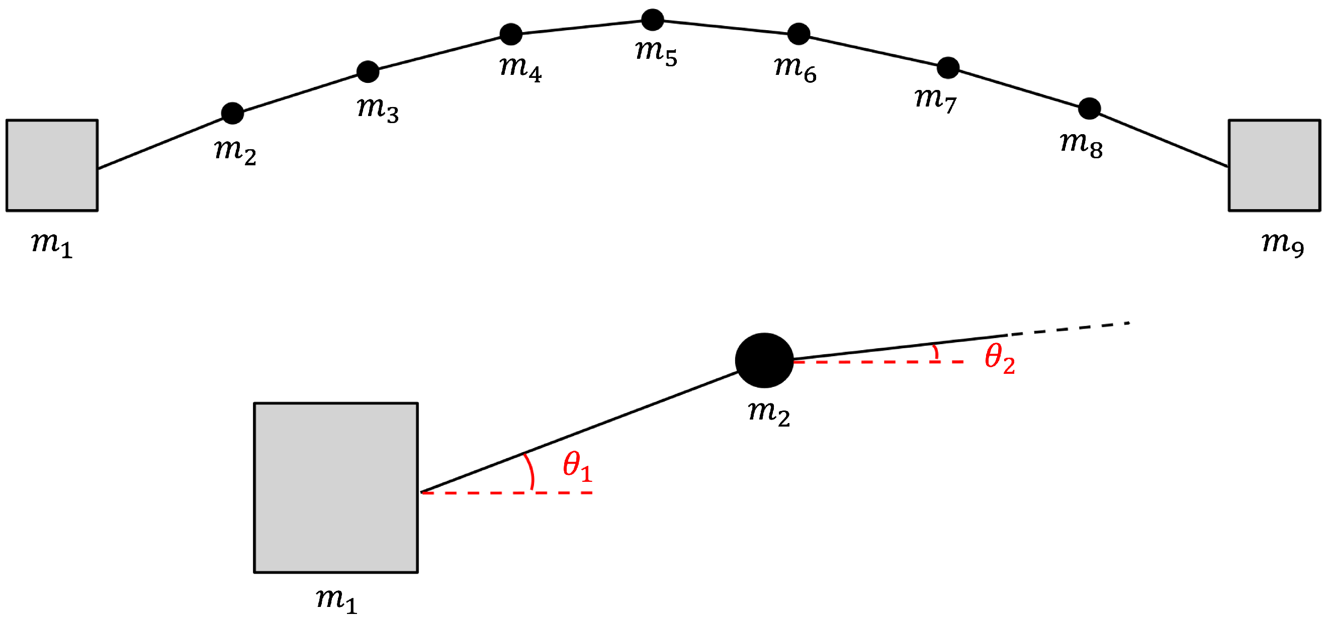
In the present research, the system can be modelled as a “barbell chain”, i.e., a series of equally spaced mass elements connected by non-conductive inextensible tethers and rotating around the centre of mass of the system, as shown in Figure 1. Each mass is a CubeSat element. The spacing between masses p and the total length l are the independent variables, defined by the mission’s required performance. The relative dynamics of all the masses can be described in a reference frame (shown in red in Figure 1) centered at the center of mass of the entire system. The x-axis is aligned with the nadir direction, the z-axis is aligned with the orbital angular momentum vector, and the y-axis completes the right-handed triad. Angles θ and ϕ represent, respectively, the in-plane and out-of-plane angle with respect to the orbital plane.
Both mission and system design are primarily driven by the following dynamic parameters:
  • Orbit: the orbital parameters are selected based on the regions of interest to ensure adequate coverage. Moreover, the orbital altitude directly affects the achievable imaging resolution.
  • Length of the tether: it determines the system baseline and, consequently, the performance of the remote sensing measurements. A longer tether is generally desirable; however, increasing the tether length also increases the volume occupied by the coiled tether within the system. Therefore, a detailed trade-off study is required to satisfy both baseline and volume constraints.
  • Spin vector: the spin vector is crucial both in terms of direction and magnitude, resulting in different baselines and periodicity of the signal.
Since this work presents a feasibility study, a general, well-established orbit is adopted for the analysis. This orbit can be subsequently refined to meet specific mission objectives. The analysis instead focuses on the effects of tether length and system spin.
Additionally, other effects such as bowing and tether elongation are not considered, as they would require high-fidelity simulations with a very high computational cost. In fact, the simulation time increases with both the number of masses and the stiffness value: higher stiffness leads to higher vibration frequencies and, consequently, to a greater number of integrator evaluations. Nevertheless, short-duration simulations have been performed to assess the validity of the inextensible tether assumption.
As shown in Figure 2, each tether segment could be oriented in different ways according to its vibration modes. Therefore, if considering, for example, a motion only in the orbital plane, each angle θ defines the direction of the related segment.
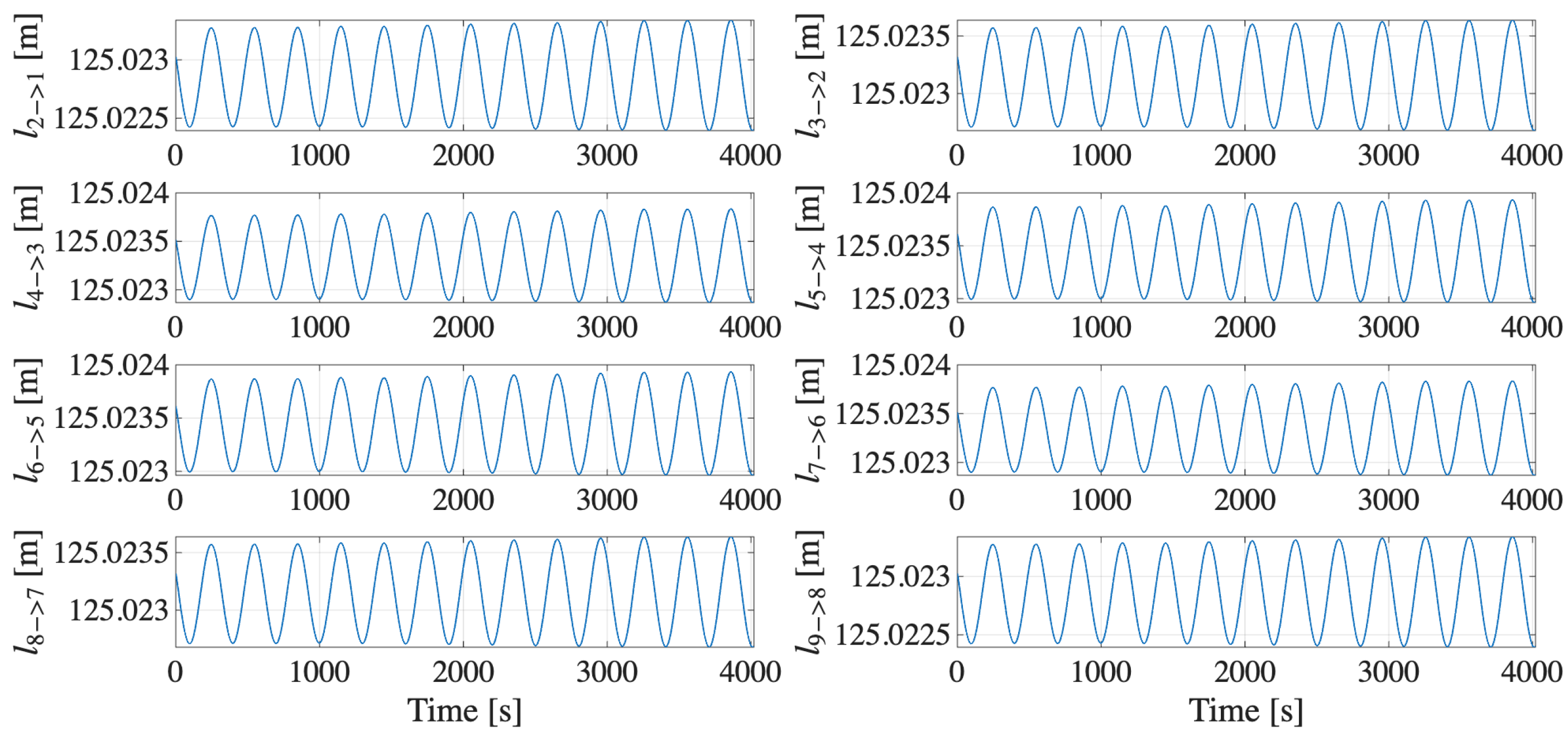
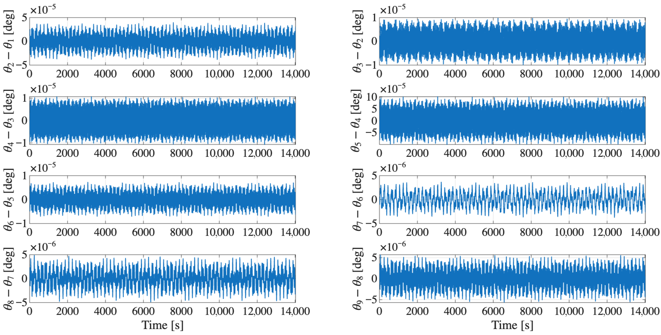
Figure 3 shows the results of a simulations with a 1 km system spinning at 0.1 rpm in its orbital plane around the Moon. The Figure highlights that, since the differences in θ of two consecutive segments is very small (order of 10 6 10 5 degrees), the tether is not bowed, but remains taut. Moreover, the distance between the masses oscillates in the order of some millimetres, as shown in Figure 4, which can be considered negligible with respect to the total tether length for most applications. Some of those analysed in this paper, namely those employing shorter wavelengths, may require knowing the relative position of the masses with greater accuracy than that achievable under these assumptions. However, in the proposed system, tether dynamics is not the only source for relative position estimation, but rather it complements the conventional sensor suite typically employed in formation flight missions.

2.2. Mission Phases and System Stability

Following orbital injection, the system stays in the stacked configuration necessary for it to fit in a limited volume within the launch vehicle. After detumbling, conceptually, the mission can be divided into four main phases: tether deployment, where the system is extended from its compact launch configuration to the full tether length; spin-up, during which the system is set into rotation using onboard propulsion; steady rotation, the operational phase where constant spin is maintained through angular momentum conservation; and reel-in/reel-out, where the tether length is adjusted to vary the system performance by exploiting angular momentum conservation rather than propellant use.
All the mission phases must be carefully and thoroughly analysed to ensure the feasibility and success of the mission. Indeed, optimization for the deployment motor control profiles should be required in order to reach the target conditions at the end of the deployment phase [25], ensuring a simpler spin-up phase. Modelling the system as a dumbbell configuration, the spin-up phase can be controlled using a hierarchical sliding mode control law, while a dynamic inversion approach is applied to ensure the stability of the out-of-plane motion [26]. Although the spin-up can be performed with the spin axis either in the orbital plane or perpendicular to it, the latter configuration is preferable, as it reduces coupling between in-plane pitch and out-of-plane roll motions [26]. These two phases are typically carried out sequentially rather than simultaneously, in order to prevent excessive tension in the tether reel mechanism due to high centrifugal forces, which could otherwise complicate deployment control [26]. The steady rotation phase can be considered stabilized if the rotation rate is at least 8 revolutions per orbit [27]. This spin rate provides adequate stabilization while minimizing the required tether strength. However, in this paper, higher spin rates are considered to incorporate a safety margin by increasing centrifugal tension, thereby keeping the tether taut and avoiding bowing. In the reel-in/reel-out phase, the stability is ensured by the conservation of angular momentum.

2.3. System Configuration

From a dynamical standpoint, two distinct orientations of the system spin axis with respect to the orbital plane are possible: the spin axis lying in the orbital plane or being perpendicular to it. Depending on the chosen orientation, the projection of the two edge modules of the tethered system (hereafter referred to as the system baseline projection) exhibits different characteristics and variations along the orbit. The baseline projection is analysed with particular interest, as it is one of the key parameters influencing the performance of the tethered-system applications discussed in Section 3.
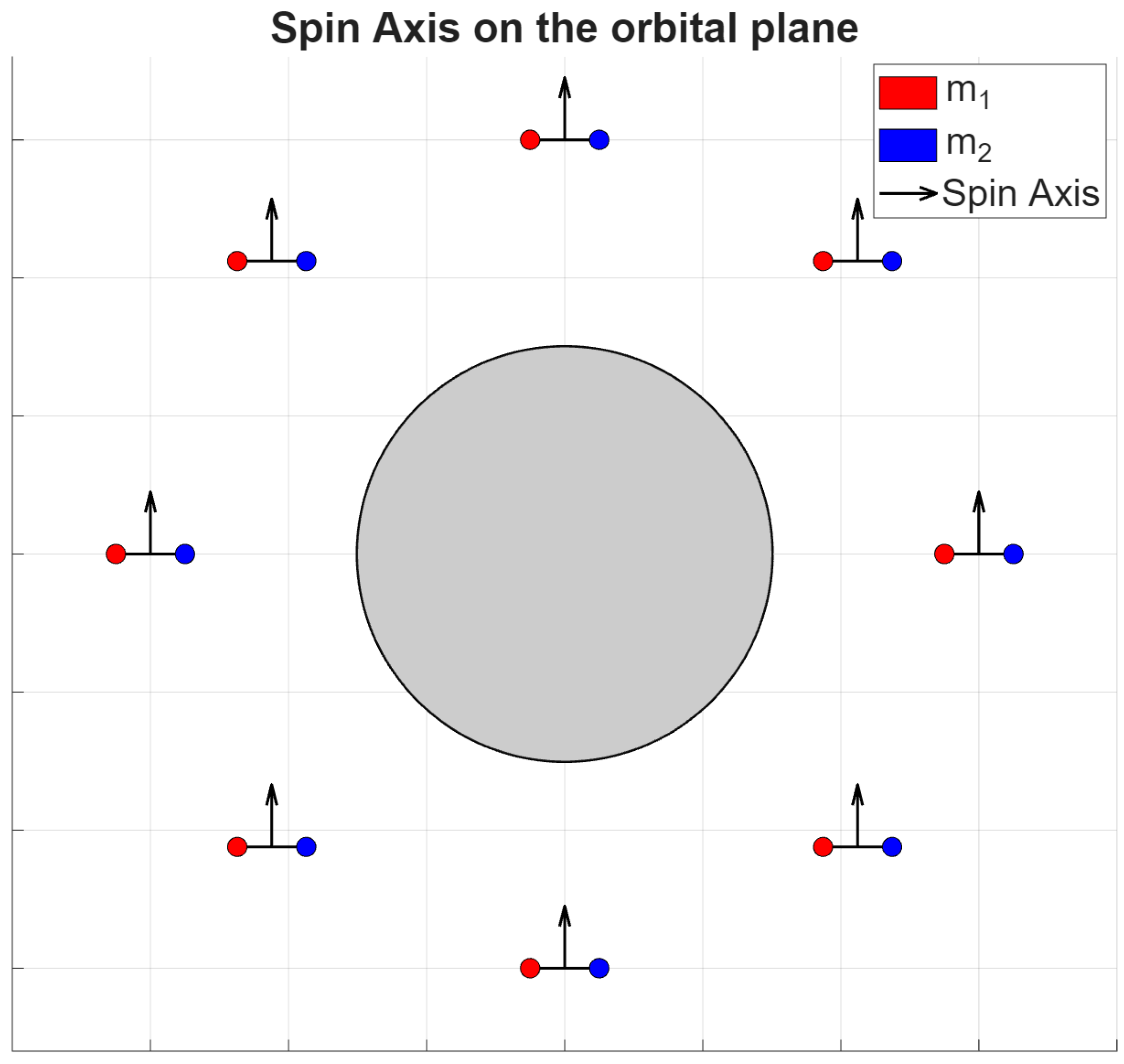
  • Spin axis lying on the orbital plane, see Figure 5. Due to geometrical constraints, in this inertially fixed configuration, the spin axis is, clearly, not always nadir-pointing, unless a constant thrust is applied. This configuration allows baseline projection variations both along and across the velocity. The baseline projection variations evolve more slowly compared with the other configuration, and the maximum baseline projection length can be achieved only twice per orbit: when the spin axis is aligned with the orbital radial direction.
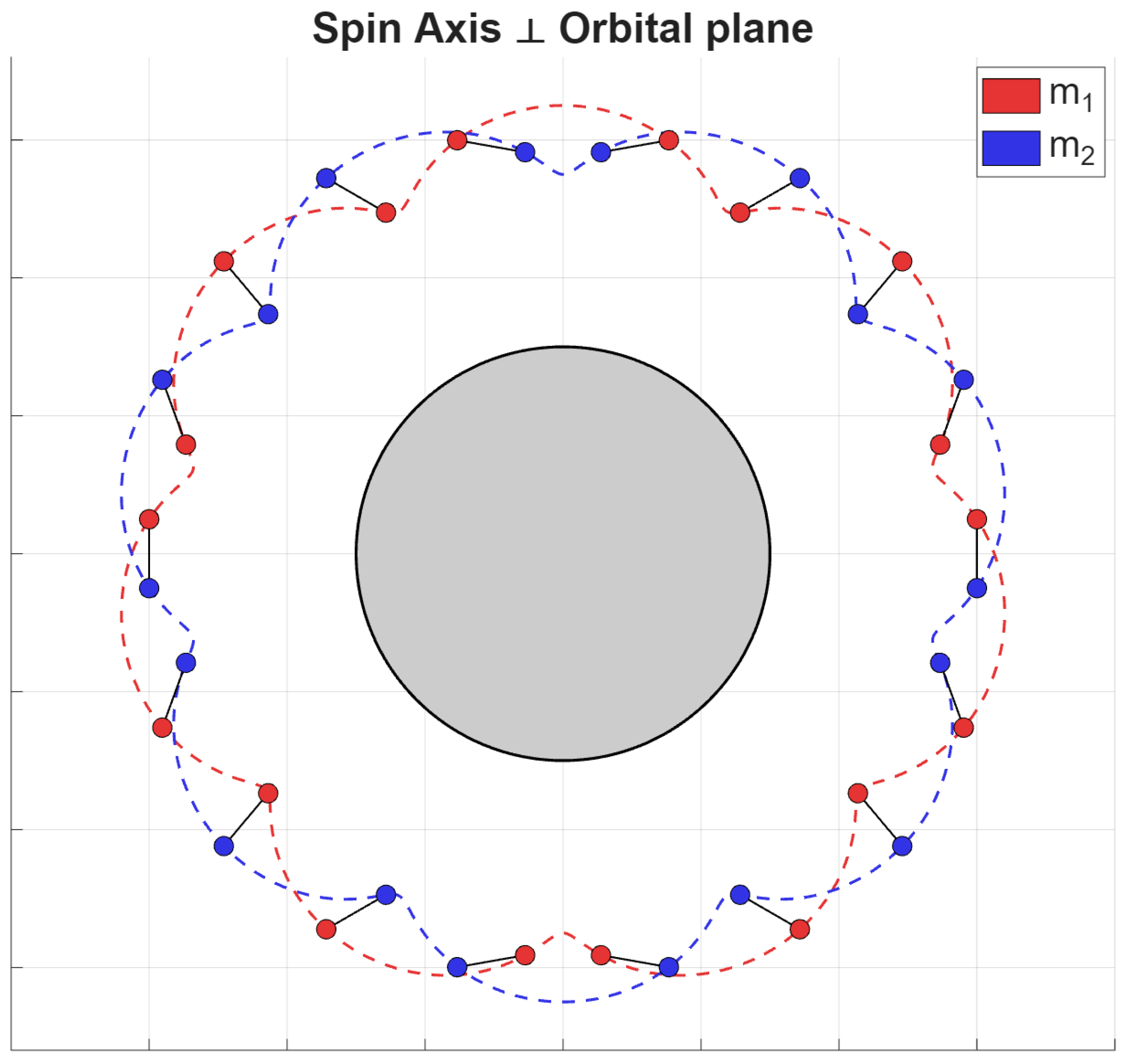
  • Spin axis perpendicular to the orbital plane, see Figure 6. The main advantage of this configuration lies in the ability to achieve the maximum baseline projection as a function of the system spin rate, and more frequently than in the previous configuration. Since the motion of the masses lies entirely within the orbital plane, this configuration allows the baseline projection to vary only along the velocity direction.

2.4. System Sizing

For the system dimensioning, the most critical aspects of the mission should be considered. These include the characteristics of the payloads integrated into the system elements to meet the mission objectives, as well as the performance and parameters of the propulsion system required for the spin-up phase. The main calculations and assumptions adopted for the system sizing are reported below, with the aim of estimating the volume and mass of the system elements and identifying the type of propulsion system required for spin-up.
During spin-up, assuming a constant angular acceleration and fixed length l, with thrust applied at the two edge elements, the impulse I t o t required per element is:
I t o t = I ω l
where ω is the angular velocity and I is the moment of inertia of the system. Neglecting the mass of the tether, I is:
I = m j = 0 n 1 ( j p ) 2 n m l 2 4
with m the mass of each element and n the number of elements in the system.
Each mass element is based on a CubeSat-standard platform, enabling modularity, scalable production, and reduced costs. The feasibility to integrate payloads for planetary observation on CubeSats is confirmed by previous studies [28,29]. CubeSat off-the-shelf optical cameras suitable for integration into the modules for stereo imaging applications are widely available on the market, with masses below 0.5 kg and volumes smaller than 1U. Representative examples include Dragonfly Aerospace cameras and the GomSpace NanoCam C1U [30]. According to literature, sounding radar payloads with compact form factors are feasible. Some examples are related to different applications of the Vector Sensor Antenna VSA technology. The specific applications along with masses and volume estimations are around 6 kg and ranging from 6U up to 8U to host the antenna in its stowed configuration and the control electronics. The dimensions depend manly on the adopted frequency range [31]. Concerning SAR systems, the feasibility to include them in CubeSats is confirmed by existing missions and concepts [29].
While tethers with lengths of several tens of kilometres have been deployed in the past [9,32], in CubeSat systems, typical target deployable tether lengths are limited to approximately 1 km [33,34]. In the present work, tether lengths in the range from 1 km up to 5 km are therefore considered, leveraging the modular architecture described in Section 2, in which the overall tether length is distributed among multiple shorter segments rather than relying on a single continuous tether.
As a general architectural concept, each mass element of the chain system is equipped with a mission-dependent sensing payload (e.g., optical cameras, SAR, or radar instruments), a tether deployment and control subsystem to achieve the final system configuration and to adjust the tether length and consequently the relative distance between sensing elements, and a set of sensors and actuators dedicated to controlling and monitoring the relative attitude between the elements. In addition, inter-element data transfer can be implemented through the tether itself by embedding a communication bus within the tether structure, thereby enabling reliable data exchange without the need for dedicated wireless communication subsystems.
The power budget is a critical aspect of space mission design, especially for systems with peculiar dynamics such as spinning tethered configurations, and becomes even more challenging when high-power-consuming payloads are involved. Although a case-by-case trade-off analysis between the system spinning configuration and orbit selection is generally required, assuming solar panels as the primary electrical power source, a dawn–dusk orbit represents the most suitable option for maximizing power generation. This applies to both configurations with the spin axis perpendicular to the orbital plane and those with the spin axis on the orbital plane; however, in the latter case, a dedicated mechanism for solar panel orientation would be required.

3. Possible Applications for Earth and Moon Observation

This section introduces a set of potential applications that are particularly well suited to spinning tethered satellite systems. Owing to their inherent capability to generate large, reconfigurable baselines and to operate in a coordinated manner, such architectures offer unique advantages for several remote sensing techniques. In the following subsections, three representative application domains are discussed: stereo imaging with optical cameras (Moon orbits), distributed radar sounding (Earth and Moon applications), and synthetic aperture radar (SAR) interferometry. For each case, the suitability of tethered systems is briefly outlined, highlighting the main performance drivers and the associated operational considerations.

3.1. Stereo Imaging

The first application that was explored to exploit the advantages of tethered architectures in remote sensing consists of a stereo camera system. By designing a barbell system composed of only two masses, and mounting a camera on each of them, it could be possible to obtain a stereo camera system having the baseline approximately equal to the length of the tether. This system can be applied in missions aiming at mapping planetary surfaces with stereo images. With respect to the commonly used configuration that employs two cameras mounted on the same platform, the tether architecture presents two main advantages:
  • The two images are taken at the same time, allowing it to observe even very fast phenomena, as well as simplifying the matching procedure between the two images by reducing temporal decorrelation;
  • It is possible to easily vary the baseline of the system, by just reeling the tether in or out, allowing a much greater flexibility in operations.
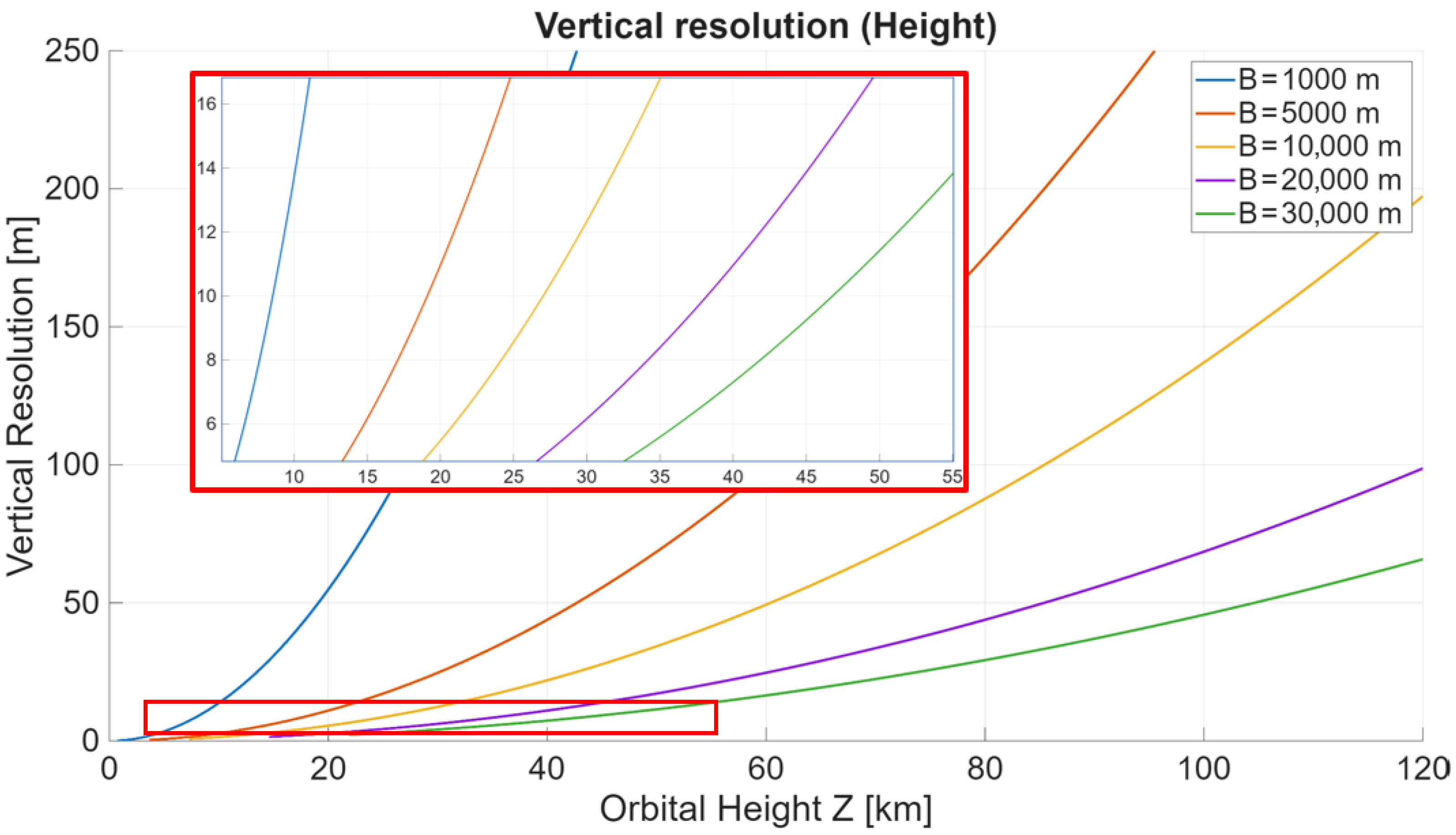
This system also presents some drawbacks when compared to the single-platform architecture. One issue is linked to the limited tether length achievable. The key performance parameter of a stereo camera system is the vertical resolution, i.e., the smallest distance variation that results in a change of one pixel in disparity. The vertical resolution is given by:
R v = Z 2 f p x B
where Z represents the distance to the observed object (in this context, the orbital altitude), f p x is the focal length expressed in pixels and B is the baseline (initially approximated as the distance between the two masses).
Figure 7 provides a graphical representation of Equation (3), illustrating how, for relatively small baseline values, the achievable vertical resolutions are significantly limited. While tethers with a length of tens of kilometres have been deployed in the past [9,32], their feasibility has not been demonstrated yet for small satellite systems. For this reason, for the system developed in this work, a lower limit was considered, analysing the cases of 1 and 5 km tether lengths.
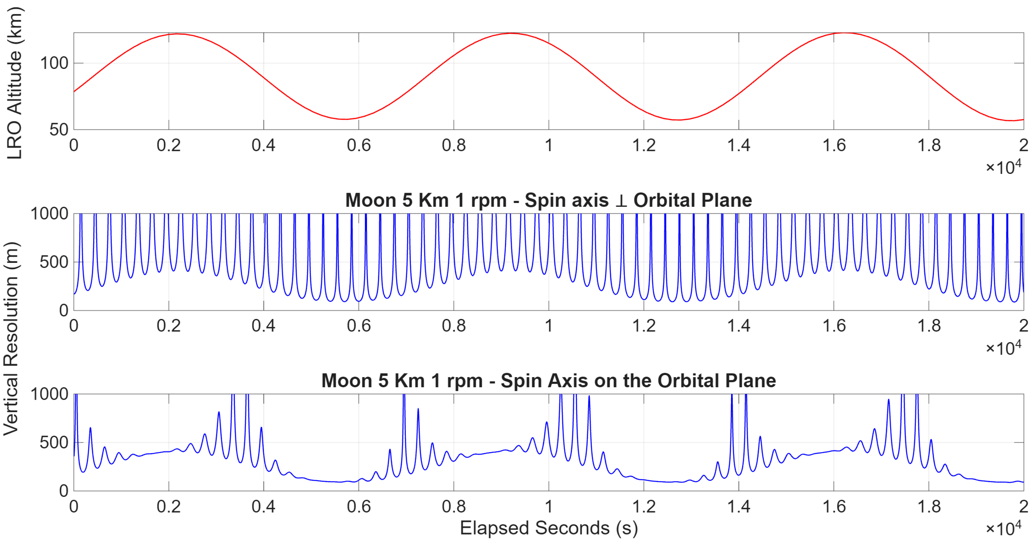
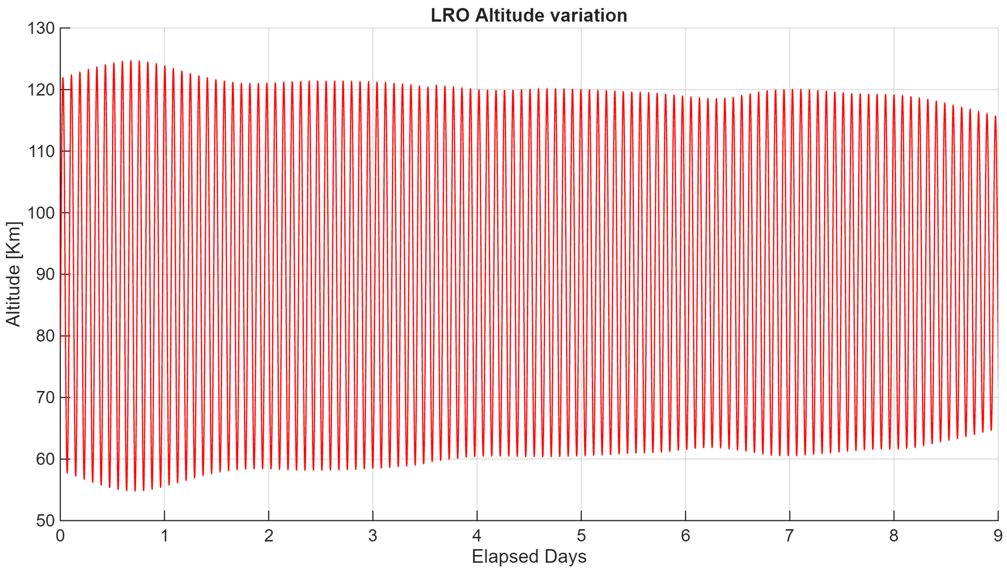
Achieving acceptable resolutions would thus require operating at very low altitudes, which is not feasible for Earth orbits and remains challenging even for lunar missions, where altitudes below 50 km have rarely been reached. To further illustrate these limitations, the orbit of an actual lunar spacecraft, the Lunar Reconnaissance Orbiter (LRO), has been considered. LRO was selected as a representative case study due to its long operational lifetime and the extensive availability of high-fidelity orbital data, making it one of the most well-characterized missions in the low-lunar-orbit domain. Ephemerides for early December 2025 were propagated [35], and the resulting altitude profile is shown in Figure 8. The figure highlights the pronounced variability of the orbital height, with the minimum altitude approaching approximately 50 km and a maximum distance from the lunar surface slightly exceeding 120 km. Such variability is a direct consequence of the highly irregular and spatially varying lunar gravitational field, which makes the maintenance of strictly circular low lunar orbits particularly challenging in the absence of dedicated station-keeping manoeuvrers. As a result, operational lunar spacecraft are typically flown on slightly eccentric or quasi-frozen trajectories that offer improved long-term stability while inherently accepting non-negligible altitude variations along the orbit [36]. For this reason, the LRO orbit provides a realistic and representative example to assess the impact of orbital altitude variability on system performance and imaging constraints. By incorporating this realistic altitude evolution into the vertical resolution Equation (3), it becomes evident that the minimum achievable resolution, slightly below a hundred meters, remains insufficient for scientific purposes, and even that change in altitude does not work in its favour; see Figure 9.
The specific configuration examined here corresponds to a barbell system with a 5 km tether length, a rotation rate of 0.1 rpm, and a spin axis orthogonal to the orbital plane. Even when considering a higher rotational speed of 1 rpm, the overall behavior does not change substantially: the resulting curve becomes more densely sampled, but its minimum envelope remains effectively unchanged.
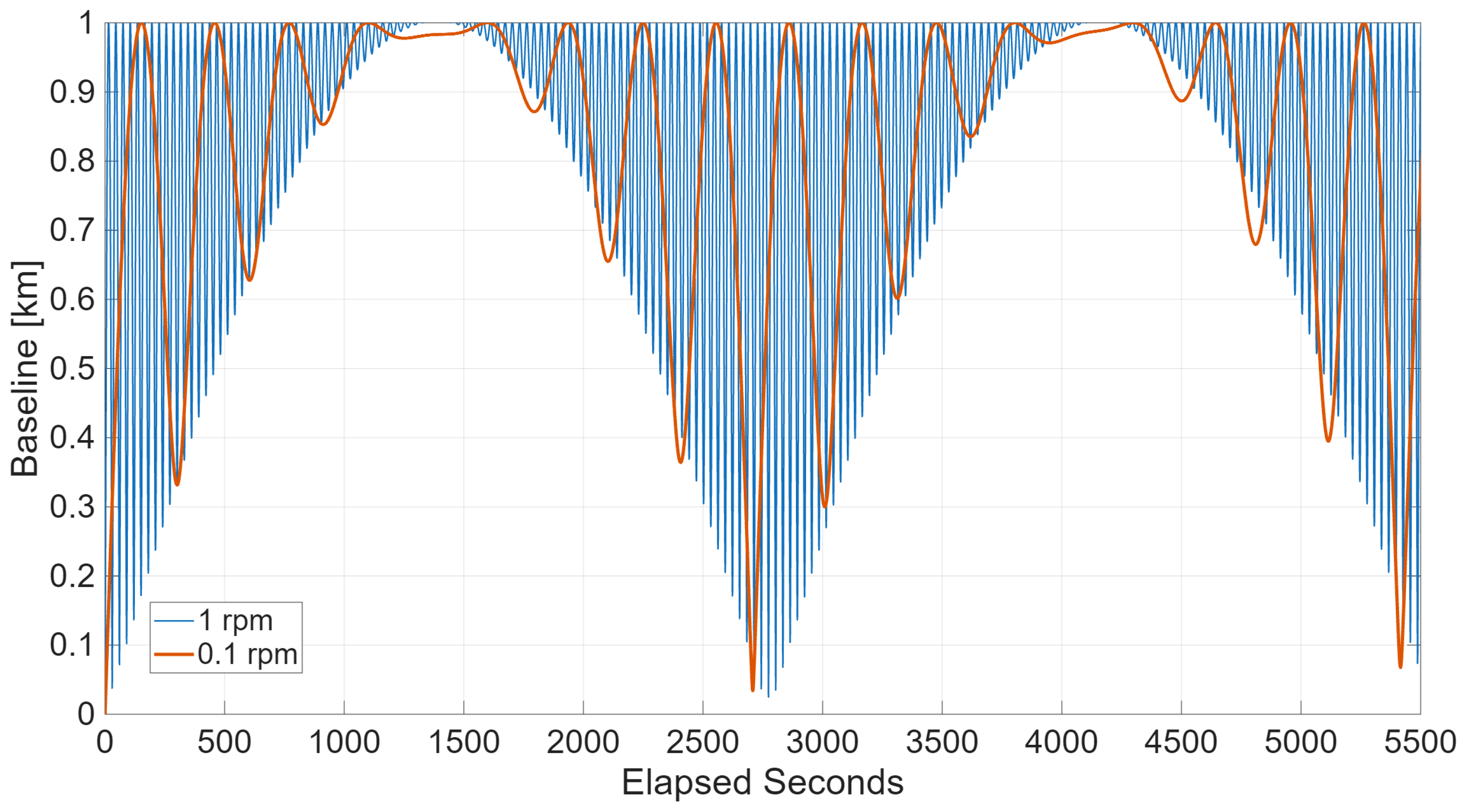
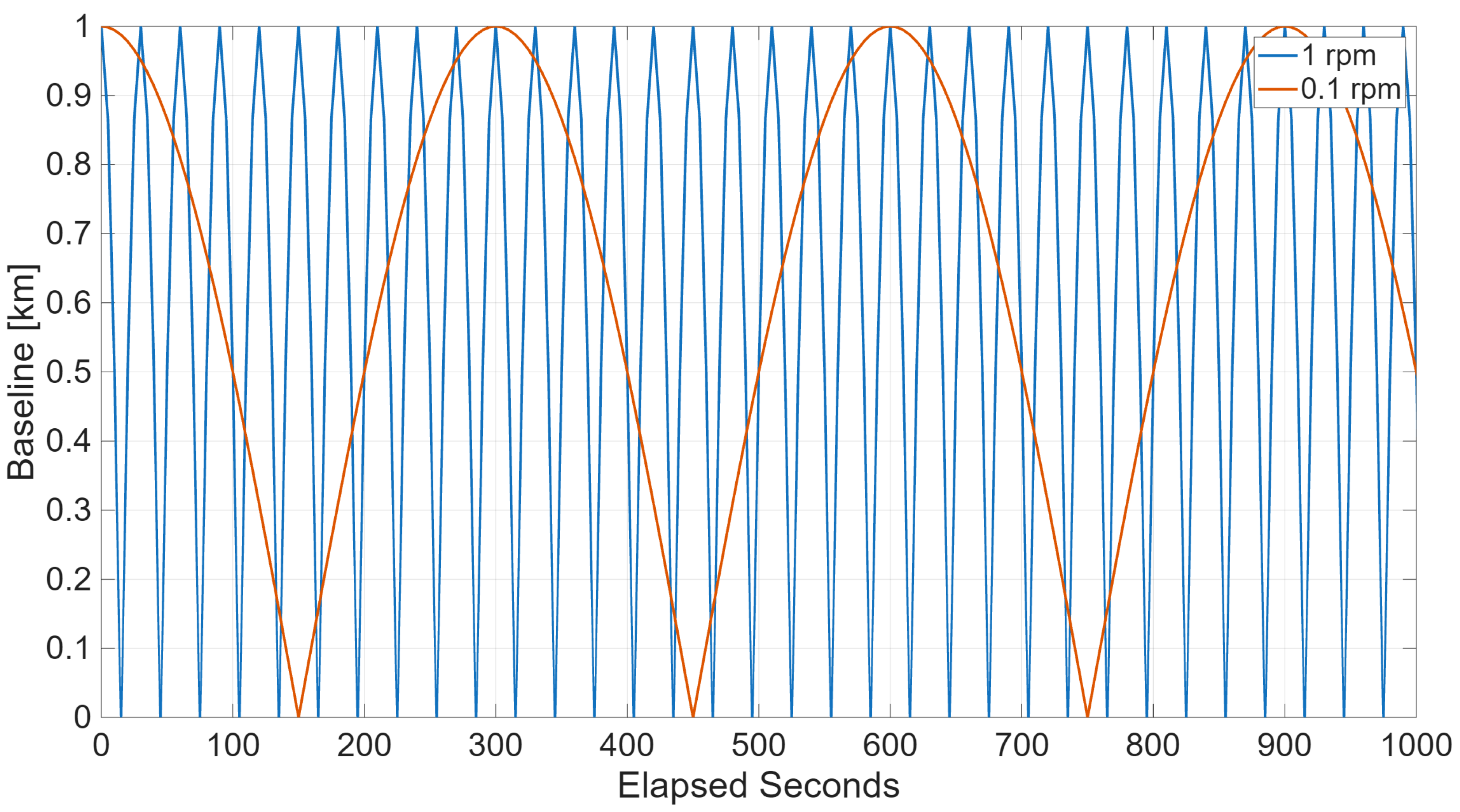
Another relevant issue concerns the system dynamics. In the nominal configuration, the time-varying geometry of the tethered system leads to a continuously changing baseline along the orbit. This effect is twofold, as previously mentioned. On the one hand, the system performance varies accordingly, following the projection of the tether onto the plane perpendicular to the local vertical. Figure 10 illustrates the baseline evolution for a 400 km Earth orbit, where the observed periodicities depend on both the system spin rate and the orbital altitude. On the other hand, this behavior requires the two cameras to operate under multiple pointing configurations, introducing a significant increase in system complexity. Nonetheless, it is worth noting that the change in the velocity of the end masses resulting from the spinning motion of the system is several orders of magnitude lower than the orbital velocity for the cases proposed. As an example, in the worst case among those considered in this work, with a spin rate of 1 rpm and a tether length of 5 km, the change in velocity induced by the spinning motion is within ±0.26 km/s, which is negligible compared to the several km/s encountered in Low Earth Orbit. The slew rates required are thus achievable with the current CubeSat attitude determination and control systems, as no significant additional requirement is imposed on their control authority with respect to traditional single-platform imaging architectures.
When the spin axis is oriented perpendicular to the orbital plane, the baseline still varies between minimum and maximum values; however, these variations occur more frequently along the orbit. In this configuration, the baseline evolution no longer admits a two-fold representation, as the geometric modulation is driven by the combined effects of orbital motion and spin dynamics. As a result, opportunities for image acquisition at the highest achievable spatial resolution and overall system performance occur more frequently, although each individual acquisition window is shorter in duration compared to the previous case. In this context, Figure 11 illustrates the baseline evolution for the 1 km tethered system along the LRO trajectory. While this configuration may offer a more uniform temporal sampling of baseline values and an increased frequency of high-performance imaging opportunities, it does not substantially mitigate the aforementioned drawbacks, and the associated challenges in terms of pointing requirements, attitude control, and overall system complexity remain largely comparable to those of the in-plane spin-axis configuration.
Overall, the present results indicate that while tethered stereo architectures offer interesting geometric flexibility and the potential for large, reconfigurable baselines, their applicability to high-resolution imaging remains fundamentally constrained by technological and orbital factors. Achieving vertical resolutions suitable for scientific mapping would require tether lengths of tens of kilometres, as demonstrated in large-scale missions such as the TSS program [37], which remain incompatible with current CubeSat-class systems. Furthermore, even with such extended baselines, meaningful resolutions could only be achieved at very low altitudes, typically a few tens of kilometres, that are neither feasible in Earth’s orbit nor easily maintainable around most planetary bodies. Consequently, the practical applicability of this system is currently limited to scenarios involving airless or low-gravity environments such as the Moon, asteroids, or icy moons, where low-altitude operations can be maintained and atmospheric drag does not inhibit system stability.

3.2. Distributed Radar Sounder

As mentioned in Section 1, a tether system composed of a chain with multiple sensing elements can provide relevant improvements to the performance of a distributed radar sounder system. On the one hand, thanks to the mechanical link provided by the tether, it is possible to greatly simplify the satellites placed on it, decreasing costs; on the other, a much better across-track resolution can be achieved for a longer period of time, due to the dynamics of the system. This is particularly evident in the case of an aerodynamically stabilized system like the one proposed in [10], which by maintaining the tether system orthogonal to the orbital velocity, achieves the maximum across-track separation between the sensors continuously. However, because of the need for an atmosphere to stabilize the system, this configuration could only be effective in low Earth orbit, while the spinning system presents potential applications also in the exploration of the Moon or other celestial bodies. The evolution of the projection of the baseline is the same as that depicted in the previous section. In this case, however, the resolution performance is limited by the projection of the baseline in the along-track and across-track directions. In particular, the across-track and along-track resolutions are given by [24]:
R c t = 0.886 λ H L a c t
R a t = λ H 2 L a t
where λ is the wavelength, H is the orbital altitude, and L a c t , L a t are the across-track and along-track projections of the tether.
To analyse the evolution of spatial resolution along the orbit, three reference cases were considered: a terrestrial polar orbit at 400 km altitude, a lunar polar orbit at 50 km altitude, and the actual orbit of the Lunar Reconnaissance Orbiter. Polar orbits were chosen for their high scientific relevance, particularly for lunar exploration where substantial solid-state water deposits are believed to exist [38]. The first two cases were analysed assuming the spin axis lies on the orbital plane, providing a simplified scenario to highlight the effect of orbital altitude on resolution.
The choice of 50 km as the reference lunar altitude is motivated by the fact that, during certain phases of its science operations, LRO maintained a mean altitude close to 50 km for limited intervals [36], representing a realistic low-lunar-orbit regime.
In addition to these idealized cases, the LRO orbit was included as a realistic benchmark and analysed under both spin-axis orientations, allowing the combined impact of orbital altitude variability and spin-axis configuration to be assessed in an operationally relevant scenario.
To evaluate the resolution of the system, three characteristic wavelengths were defined:
  • 4.2 cm (X-band)—analogous to the wavelength used by the Mini-RF instrument aboard NASA’s Lunar Reconnaissance Orbiter (LRO) [39], designed for polar ice detection;
  • 70 cm (P-band)—consistent with the radar wavelength planned for the BIOMASS mission [40] by the the European Space Agency (ESA), aimed at global forest biomass observation;
  • 33 m (HF-band)—corresponding to the wavelength of the RIME instrument on board ESA’s JUICE mission [41], designed for subsurface geological analysis of icy moons.
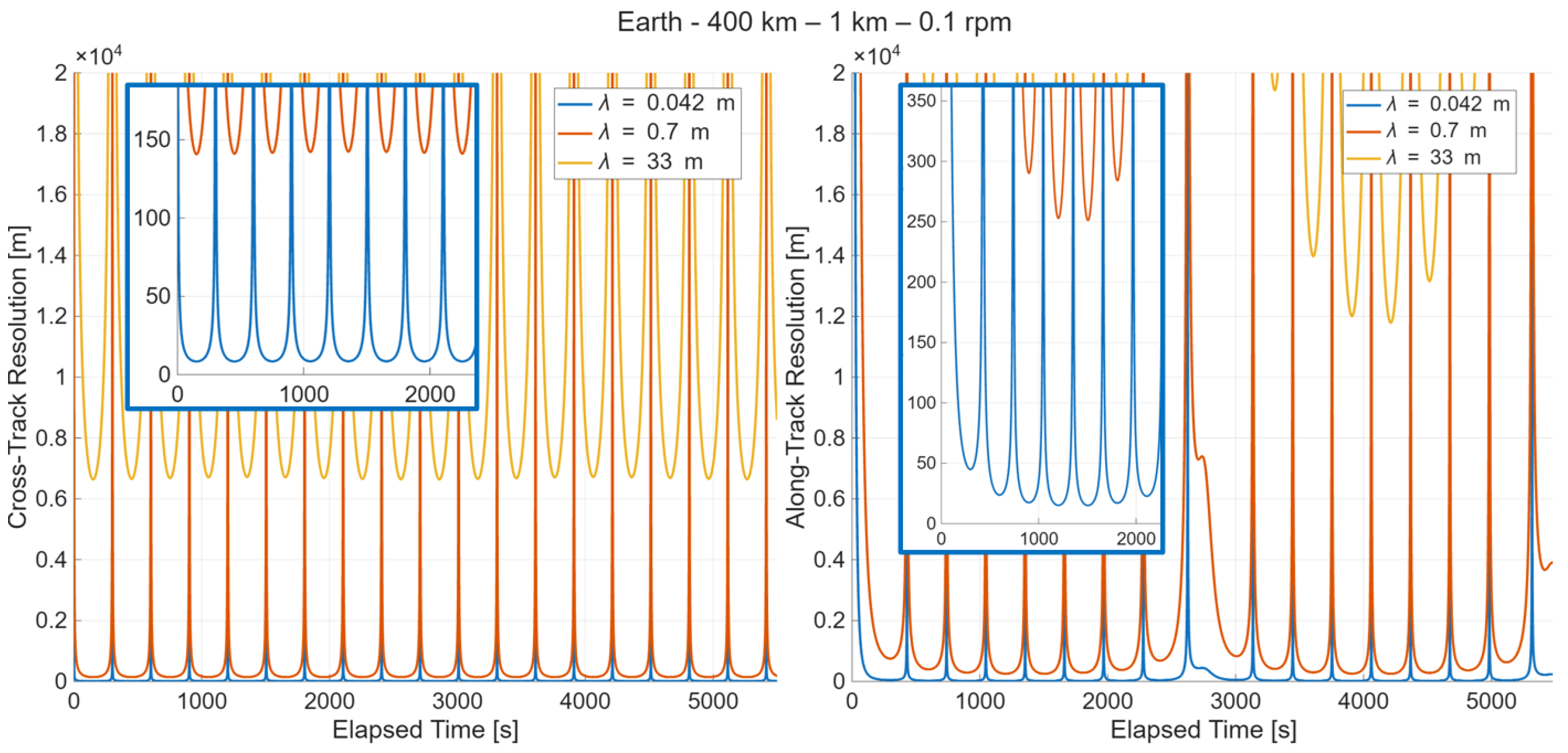
Figure 12 and Figure 13 present the cross-track and along-track spatial resolution for the two idealized reference cases, namely a terrestrial polar orbit at 400 km and a lunar polar orbit at 50 km, respectively, both assuming the spin axis to lie on the orbital plane. The overall temporal trends appear qualitatively similar in the two cases, as they are governed by the same geometric configuration and system parameters, with the orbital altitude representing the primary differentiating factor. As expected, the lower altitude associated with the lunar case results in a systematic improvement of the achievable spatial resolution across all considered wavelengths, as is clearly visible in the downward shift of the resolution curves.
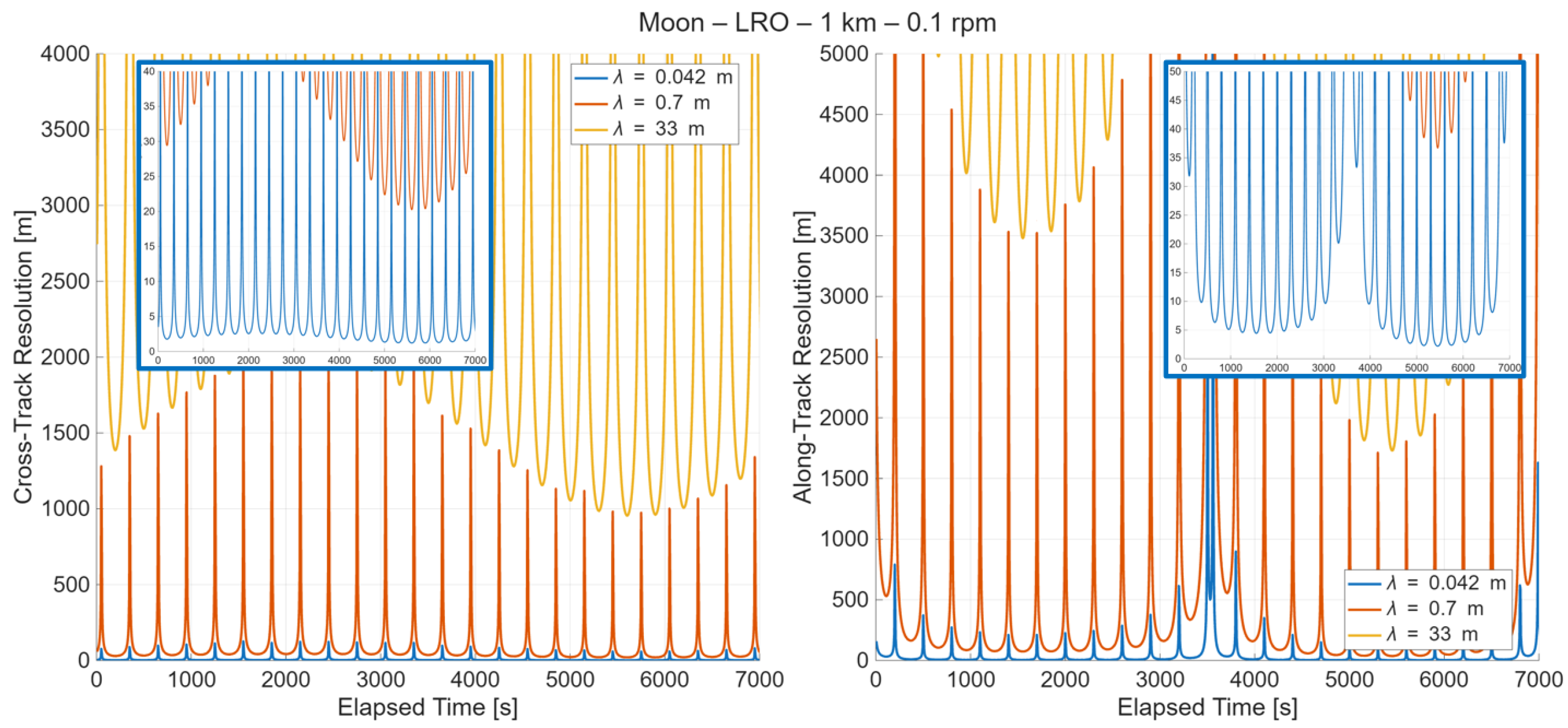
A more complex and informative behavior emerges when considering the cases based on the actual LRO trajectory, shown in Figure 14 and Figure 15. Figure 14 refers to the configuration in which the spin axis lies on the orbital plane, allowing both cross-track and along-track resolutions to be defined. In this case, the resolution profiles exhibit a distinct oscillatory pattern, which directly reflects the altitude variations along the LRO orbit. These undulations highlight the sensitivity of the system performance to orbital height changes, emphasizing the impact of non-circular low lunar orbits on the achievable resolution.
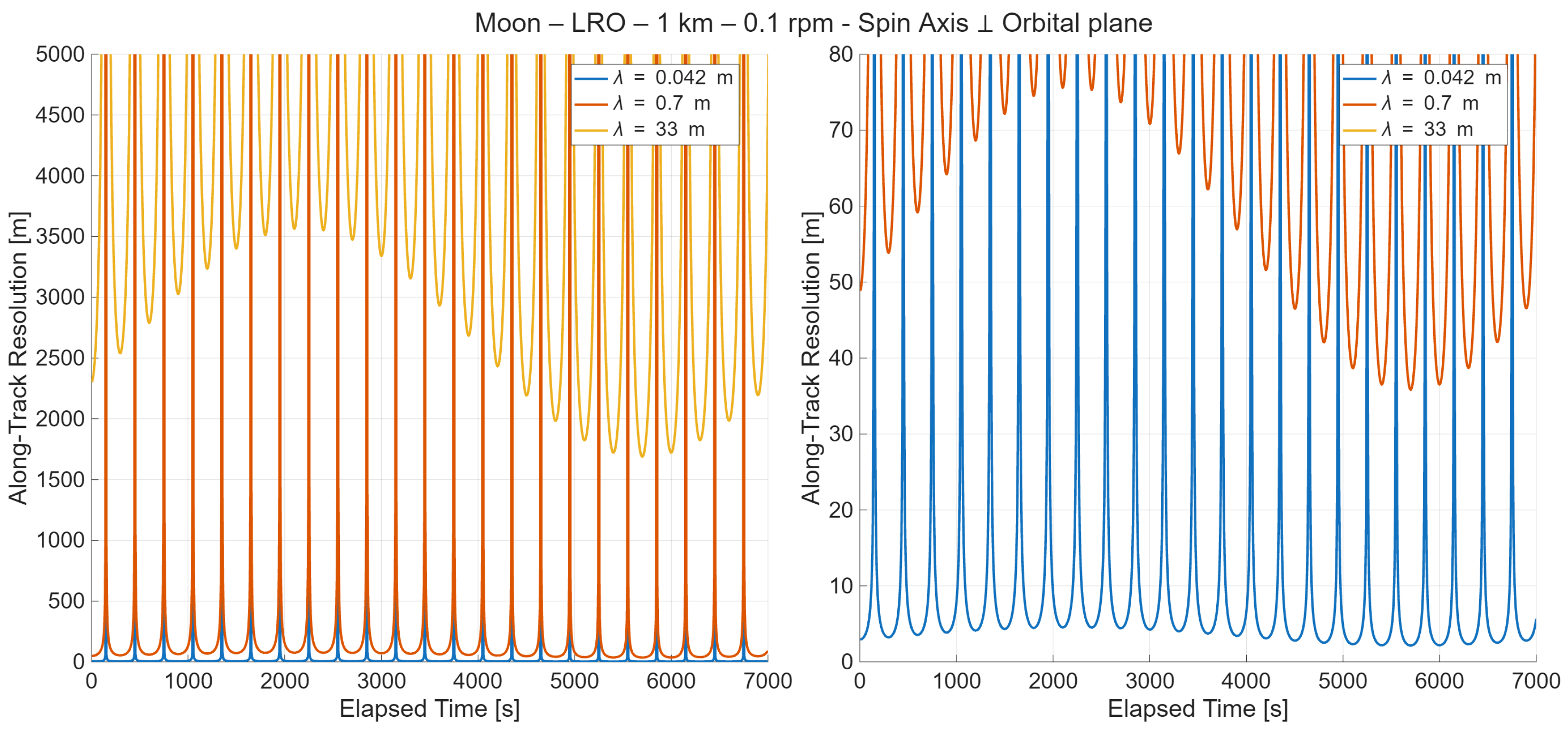
Conversely, Figure 15 illustrates the case in which the spin axis is oriented perpendicular to the orbital plane. Due to geometric constraints, this configuration precludes the definition of a cross-track baseline, resulting in the loss of cross-track resolution. However, the along-track resolution remains available and exhibits a markedly different temporal behavior compared to the previous case, no longer characterized by the two-fold periodicity observed when the spin axis lies on the orbital plane and which could be advantageous for applications requiring consistent along-track sampling or imaging continuity. This configuration therefore demonstrates how the spin-axis orientation not only affects the availability of resolution components, but also fundamentally alters their temporal evolution along the orbit.
Furthermore, based on the resolution curves and by setting a threshold resolution for the different wavelengths, it is possible to determine the percentage of time during which the system meets the specified performance requirements. The threshold values for ground resolution were defined according to typical figures associated with radar systems operating in the corresponding frequency bands and, following a conservative approach, were set to 50 m ( λ = 4.2 cm), 1000 m ( λ = 70 cm), and 15,000 m ( λ = 33 m). The resulting percentages were computed exclusively for configurations in which the system spin axis lies on the orbital plane, ensuring the simultaneous availability of both cross-track and along-track resolution components and enabling a consistent comparison between them.
Within this framework, three reference scenarios were analysed: a terrestrial orbit at an altitude of 400 km and two lunar orbits at fixed altitudes of 100 km and 50 km, respectively. Table 1 summarises the results, highlighting a clear dependence of the fraction of time spent below the prescribed resolution thresholds on orbital altitude.
The lunar scenarios exhibit substantially higher percentages than the terrestrial case, reflecting the systematic improvement in achievable spatial resolution enabled by lower orbital heights. Among the lunar configurations, the 50 km orbit consistently provides the highest fraction of time below threshold across all considered wavelengths, confirming that reduced altitude directly translates into enhanced and more persistent imaging performance.
For all analysed cases, differences between cross-track and along-track percentages arise from the distinct baseline evolution. Nevertheless, the overall trends remain consistent, indicating that orbital altitude is the dominant factor governing the fraction of time during which the system satisfies the resolution requirement. Quantitatively, the percentage of time below threshold increases from approximately 42% for the Earth orbit at 400 km altitude (for λ = 33 m) to nearly 90% for the lunar orbit at 50 km. For shorter wavelengths, compliance exceeds 95–98% across all low-altitude lunar configurations. Overall, these results demonstrate that reducing orbital altitude systematically enhances both the persistence and robustness of high-resolution performance.

3.3. SAR Interferometry

One of the key peculiarities of the proposed tethered system is the ability to easily modify the distance between the sensing masses by reeling the tether in or out, without the need for propellant. This capability, already relevant for the other applications discussed, is particularly valuable in the context of synthetic aperture radar interferometry (InSAR). In conventional spaceborne SAR systems, the achievable interferometric baseline is constrained by orbital control accuracy and fuel consumption, directly limiting system flexibility and performance [42].
InSAR requires highly accurate knowledge of the relative baseline between the two antennas to enable precise phase processing and height retrieval. The mechanical constraint imposed by a tether can provide intrinsically stable and well-defined baseline geometry, potentially improving baseline determination accuracy when combined with standard calibration and orbit determination techniques [43]. Moreover, the ability to dynamically adjust the baseline length during the mission enables substantial operational flexibility, allowing the system to alternate between different observation modes.
In particular, interferograms acquired with small baselines can be used to assist the phase unwrapping of interferograms obtained with larger baselines, a well-established strategy to mitigate phase ambiguities and reduce unwrapping errors [44,45]. This capability is especially advantageous for the exploration of celestial bodies where existing digital elevation models (DEMs) are affected by significant uncertainties or limited spatial resolution, which directly impacts the reliability of DEM-assisted phase unwrapping [42,45]. A variable-baseline tethered system could therefore progressively refine topographic knowledge by exploiting a sequence of interferometric acquisitions with increasing baseline lengths.
Furthermore, the simultaneous acquisition enabled by the tethered configuration inherently eliminates temporal decorrelation effects between the two SAR measurements, which are a major limitation in conventional repeat-pass InSAR systems [42]. This is particularly relevant in planetary environments characterized by surface changes driven by dust transport, volatile cycles, or ionospheric variability, where temporal decorrelation can severely degrade interferometric coherence.
Clearly, changing the tether length modifies the system’s spin rate in accordance with the conservation of angular momentum, thereby affecting the effective acquisition frequency and revisit geometry. While the operational implications of this coupling between baseline length and rotational dynamics require detailed analysis, preliminary considerations indicate that, for baseline values typically employed in interferometric applications (on the order of 10–102 m) [43,44], the resulting acquisition frequency remains compatible with SAR imaging requirements, and does not pose a fundamental limitation to the proposed concept.

4. Conclusions and Future Developments

This work investigated the potential of spinning tethered satellite systems as a flexible and scalable architecture for remote sensing applications, with a specific focus on stereo imaging, distributed radar sounding, and SAR interferometry.
The feasibility of performing observation missions using spinning tethered CubeSat platforms has been demonstrated from a system-level perspective, taking into account past missions, the availability of off-the-shelf CubeSat components, and the current state of tether technology, including its advancements and limitations.
By exploiting the mechanical linkage offered by the tether and the controllable spin dynamics, such systems enable the realization of large and reconfigurable baselines without the need for continuous propellant expenditure. Moreover, this adds a constraint in relative position and attitude estimation pipelines complementing traditional sensors, enabling better performance. Compared to conventional free-flying formations, this architecture offers clear advantages in terms of baseline stability, mass efficiency, and operational flexibility. Beyond application-specific results, the main contribution of this work lies in the adoption of a system-level framework that identifies the key architectural and dynamical parameters driving the performance of multiple observation techniques within a unified CubeSat-scale design space.
The main limitation for remote sensing performance was identified in the maximum tether length. While, as highlighted throughout the paper, performance competitive with or superior to satellite formations can be achieved with the current technologies for some applications, an increase in tether length deployable by CubeSat-scale systems would allow a significant improvement in applications such as simultaneous stereo imaging. The effects of choosing different spin axis geometries were explored, highlighting how they could benefit different applications.
The analyses were conducted for representative orbital scenarios around the Earth and the Moon; however, the proposed methodology and performance assessment framework are inherently general and can be readily extended to other planetary bodies, provided that the relevant orbital and gravitational parameters are taken into account.
Despite these promising results, several challenges remain. The time-varying geometry of spinning tethered systems introduces non-trivial pointing and attitude requirements for the payloads, increasing the overall system complexity. Additionally, deployment dynamics, tether tension management, and long-term stability—particularly in highly perturbed environments such as low lunar orbit—require further investigation to ensure operational robustness. These aspects are especially critical for applications relying on very precise and repeatable baseline knowledge.
Overall, the results presented in this paper indicate that spinning tethered systems represent a viable and competitive solution for future Earth and planetary remote sensing missions. While additional work is required to address control, deployment, and operational constraints, the demonstrated gains in spatial resolution, configurability, and propellant-free baseline reconfiguration suggest that tether-based architectures could play a significant role in next-generation observation missions across a wide range of celestial bodies.

Author Contributions

Conceptualization, S.E.; methodology, S.E., N.T., G.T. and G.A.; software, G.A., N.T.; investigation, S.E., N.T., G.T. and G.A.; writing—original draft preparation, S.E., N.T., G.T. and G.A.; writing—review and editing, L.O., A.V.; and supervision, C.B., G.C. and E.C.L. All authors have read and agreed to the published version of the manuscript.

Funding

This study was carried out within the Space It Up project funded by the Italian Space Agency, ASI, and the Ministry of University and Research, MUR, under contract n. 2024-5-E.0 - CUP n. I53D24000060005.

Data Availability Statement

The datasets presented in this article are not readily available because they are part of an ongoing study. Requests to access the datasets should be directed to nicolo.trabacchin@phd.unipd.it.

Conflicts of Interest

The authors declare no conflicts of interest.

References

  1. Sánchez-Arriaga, G.; Naghdi, S.; Wätzig, K.; Schilm, J.; Lorenzini, E.; Tajmar, M.; Urgoiti, E.; Tarabini Castellani, L.; Post, A. The E.T.PACK Project: Towards a fully passive and consumable - less deorbit kit based on low-work-function tether technology. Acta Astronaut. 2020, 177, 821–827. [Google Scholar] [CrossRef] [Scilit]
  2. Seubert, C.R.; Schaub, H. Tethered Coulomb Structures: Prospects and Challenges. J. Astronaut. Sci. 2009, 57, 347–368. [Google Scholar] [CrossRef] [Scilit]
  3. Mckenzie, D.; Cartmell, M. Modelling of Tethered Space-Web Structures. J. Br. Interplanet. Soc. 2008, 61, 24–31. [Google Scholar]
  4. International Space Elevator Consortium; Wright, D.H. Building the Space Elevator Tether. J. Br. Interplanet. Soc. 2023, 76, 225–231. [Google Scholar] [CrossRef] [Scilit]
  5. Enzo, S.; Bettanini, C.; Lorenzini, E.C. Application of tether technology to generate artificial gravity in a slowly-spinning system for human exploration missions. In Proceedings of the International Astronautical Conference, Milan, Italy, 14–18 October 2024. [Google Scholar] [CrossRef] [Scilit]
  6. Hall, T. Artificial Gravity Visualization, Empathy, and Design. In Proceedings of the Space 2006, San Jose, CA, USA, 19–21 September 2006. [Google Scholar] [CrossRef] [Scilit]
  7. Keller, T.; Strauss, A.; Szpalski, M. Prevention of bone loss and muscle atrophy during manned space flight. Microgravity Q. MGQ 1992, 2, 89–102. [Google Scholar] [PubMed]
  8. Kornuta, J.A.; Guo, S. Momentum exchange tether as a hypersonic parachute during reentry for human missions. J. Spacecr. Rocket. 2010, 47, 571–579. [Google Scholar] [CrossRef] [Scilit]
  9. Kruijff, M.; Heide, E.; Ockels, W. Data Analysis of a Tethered SpaceMail Experiment. J. Spacecr. Rocket. 2009, 46, 1272–1287. [Google Scholar] [CrossRef] [Scilit]
  10. Aliberti, S.; Quadrelli, M.B.; Romano, M. A distributed space radar sounder using a cross-track flying tethered satellite system. Acta Astronaut. 2024, 221, 266–282. [Google Scholar] [CrossRef] [Scilit]
  11. Bombardelli, C.; Lorenzini, E.C.; Quadrelli, M.B. Formation pointing dynamics of tether-connected architecture for space interferometry. J. Astronaut. Sci. 2004, 52, 475–493. [Google Scholar] [CrossRef] [Scilit]
  12. Lorenzini, E.; Bombardelli, C.; Cosmo, M.; Harwit, M.; Leisawitz, D.; Farley, R.; Rinehart, S.; Quinn, D.; Miller, D. Far-infrared/submillimeter astronomical interferometry with spaceborne tether formations. Astrophys. Space Sci. 2006, 302, 225–239. [Google Scholar] [CrossRef] [Scilit]
  13. Moccia, A.; Vetrella, S. A tethered interferometric synthetic aperture radar (SAR) for a topographic mission. IEEE Trans. Geosci. Remote Sens. 1992, 30, 103–109. [Google Scholar] [CrossRef] [Scilit]
  14. Haynes, M.S.; Beauchamp, R.M.; Khazendar, A.; Mazouz, R.; Quadrelli, M.B.; Focardi, P.; Hodges, R.E.; Bertiger, W.; Bienert, N. Debris: Distributed Element Beamformer Radar for Ice and Subsurface Sounding. In 2021 IEEE International Geoscience and Remote Sensing Symposium IGARSS; IEEE: New York, NY, USA, 2021; pp. 651–654. [Google Scholar] [CrossRef] [Scilit]
  15. Mazouz, R.; Quadrelli, M.; Beauchamp, R. Dynamics and Optimal Control for Free-Flight and Tethered Arrays in Low Earth Orbit. In Proceedings of the 2021 IEEE Aerospace Conference (50100); IEEE: New York, NY, USA, 2021; pp. 1–20. [Google Scholar] [CrossRef] [Scilit]
  16. Kirk, R.L.; Howington-Kraus, E.; Rosiek, M.R.; Anderson, J.A.; Archinal, B.A.; Becker, K.J.; Cook, D.A.; Galuszka, D.M.; Geissler, P.E.; Hare, T.M.; et al. Ultrahigh resolution topographic mapping of Mars with HiRISE stereo images: Meter-scale slopes of candidate Phoenix landing sites. J. Geophys. Res. Planets 2008, 113, E00A24. [Google Scholar] [CrossRef] [Scilit]
  17. Henriksen, M.; Manheim, M.; Burns, K.; Seymour, P.; Speyerer, E.; Deran, A.; Boyd, A.; Howington-Kraus, E.; Rosiek, M.; Archinal, B.; et al. Extracting accurate and precise topography from LROC narrow angle camera stereo observations. Icarus 2017, 283, 122–137. [Google Scholar] [CrossRef] [Scilit]
  18. Neukum, G.; Jaumann, R.; Basilevsky, A.; Dumke, A.; van Gasselt, S.; Giese, B.; Hauber, E.; Head, J.; Heipke, C.; Hoekzema, N.; et al. HRSC: High Resolution Stereo Camera; European Space Agency, (Special Publication) ESA SP: Noordwijk, The Netherlands, 2009; pp. 15–74. [Google Scholar]
  19. Thomas, N.; Cremonese, G.; Ziethe, R.; Gerber, M.; Brändli, M.; Bruno, G.; Erismann, M.; Gambicorti, L.; Gerber, T.; Ghose, K.; et al. The Colour and Stereo Surface Imaging System (CaSSIS) for the ExoMars Trace Gas Orbiter. Space Sci. Rev. 2017, 212, 1897–1944. [Google Scholar] [CrossRef] [Scilit]
  20. Virkki, A.K.; Neish, C.D.; Rivera-Valentín, E.G.; Bhiravarasu, S.S.; Hickson, D.C.; Nolan, M.C.; Orosei, R. Planetary Radar—State-of-the-Art Review. Remote Sens. 2023, 15, 5605. [Google Scholar] [CrossRef] [Scilit]
  21. Soldovieri, F.; Gennarelli, G.; Su, Y.; Ding, C.; Du, W. Microwave tomography for Lunar Penetrating Radar data processing in Chang’e 4 mission. Sci. Rep. 2025, 15, 5219. [Google Scholar] [CrossRef] [Scilit]
  22. Mattei, E.; Lauro, S.; Vannaroni, G.; Cosciotti, B.; Bella, F.; Pettinelli, E. Dielectric measurements and radar attenuation estimation of ice/basalt sand mixtures as martian Polar Caps analogues. Icarus 2014, 229, 428–433. [Google Scholar] [CrossRef] [Scilit]
  23. Blankenship, D.D.; Moussessian, A.; Chapin, E.; Young, D.A.; Wesley Patterson, G.; Plaut, J.J.; Freedman, A.P.; Schroeder, D.M.; Grima, C.; Steinbrügge, G.; et al. Radar for Europa Assessment and Sounding: Ocean to Near-Surface (REASON). Space Sci. Rev. 2024, 220, 51. [Google Scholar] [CrossRef] [Scilit]
  24. Carrer, L.; Gerekos, C.; Bovolo, F.; Bruzzone, L. Distributed Radar Sounder: A Novel Concept for Subsurface Investigations Using Sensors in Formation Flight. IEEE Trans. Geosci. Remote Sens. 2019, 57, 9791–9809. [Google Scholar] [CrossRef]
  25. Zhang, Y.; Jiang, X.; Bai, Z.; Guo, J.w.; Wei, C. Dynamics and rebound behavior analysis of flexible tethered satellite system in deployment and station-keeping phases. Def. Technol. 2021, 18, 509–523. [Google Scholar] [CrossRef] [Scilit]
  26. Li, Z.; Meng, Z.; Huang, P. Spin-up Control of Tethered Space Station for Artificial Gravity Task. In 2019 IEEE International Conference on Robotics and Biomimetics (ROBIO); IEEE: New York, NY, USA, 2019; pp. 2502–2508. [Google Scholar] [CrossRef] [Scilit]
  27. Pearson, J.; Levin, E.; Carroll, J.; Oldson, J. Orbital Maneuvering with Spinning Electrodynamic Tethers. In Proceedings of the 2nd International Energy Conversion Engineering Conference, Providence, RI, USA, 16–19 August 2004. [Google Scholar] [CrossRef] [Scilit]
  28. Xiang, Z. A survey and assessment of the capabilities of Cubesats for Earth observation. Acta Astronaut. 2012, 74, 50–68. [Google Scholar] [CrossRef] [Scilit]
  29. Golkar, A.; Cataldo, G.; Osipova, K. Small satellite synthetic aperture radar (SAR) design: A trade space exploration model. Acta Astronaut. 2021, 187, 458–474. [Google Scholar] [CrossRef] [Scilit]
  30. Taleb, I.; Lassakeur, A. A survey of compact optical cameras for Earth observation cubesat missions. In Proceedings of the 73rd International Astronautical Congress (IAC), Paris, France, 18–22 September 2022. [Google Scholar] [CrossRef] [Scilit]
  31. Holt, J.; Nerozzi, S.; Knapp, M.; Paritsky, L.; Fenn, A.; Thompson, E.; Aguilar, R. Advanced Radar Sounding and Imaging on SmallSat and CubeSat Missions Across the Solar System with Vector Sensor Antennas. In Proceedings of the EPSC-DPS Joint Meeting 2025, Helsinki, Finland, 7–12 September 2025; EPSC-DPS2025-1151. Volume 2025. [Google Scholar] [CrossRef] [Scilit]
  32. Dobrowolny, M.; Stone, N.H. A technical overview of TSS-1: The first Tethered-Satellite system mission. Il Nuovo C 1994, 17, 1–12. [Google Scholar] [CrossRef] [Scilit]
  33. Hoyt, R.; Newton, T.; Barnes, I.; Shepherd, J.; Frank, S.S.; Slostad, J.; Jaroux, B.; Twiggs, R. Early results of the multi-application survivable tether (MAST) space tether experiment. In Proceedings of the 21st Annual AIAA/USU Conference on Small Satellites, Logan, UT, USA, 13–16 August 2007. SSC07-VII-8/048. [Google Scholar]
  34. Coffey, S.; Crippa, C.; Dutchover, G.; Brunner, M.D.; Sibert, Z.; Kindl, S.; Galysh, I.; Enloe, C.L.; Carroll, J. Tepce: A Tethered Electrodynamic Propulsion Cubesat Experiment; Report of U. S. Naval Research Laboratory Washington, NRL/8230/FR–2022/1; U.S. Naval Research Laboratory: Washington, DC, USA, 2022.
  35. Jet Propulsion Laboratory. HORIZONS Web-Interface. 2025. Available online: https://ssd.jpl.nasa.gov/horizons/ (accessed on 16 November 2025).
  36. Mesarch, M.A. Long-Term Orbit Operations for the Lunar Reconnaissance Orbiter. In Proceedings of the 2023 AAS/AIAA Astrodynamics Specialist Conference, Big Sky, MT, USA, 13–17 August 2023. number AAS-23-234. [Google Scholar]
  37. Stone, N.; Bonifazi, C. The TSS-1R Mission: Overview and scientific context. Geophys. Res. Lett. 1998, 25, 409–412. [Google Scholar] [CrossRef] [Scilit]
  38. Ambrose, W.A.; Cutright, B.L. Water Ice Resources on the Moon. Gulf Coast Assoc. Geol. Soc. Trans. 2023, 72, 231–241. [Google Scholar]
  39. Patterson, G.; Bhiravarasu, S.; Fassett, C.; Thomson, B.; Cahill, J.; Chakraborty, T.; Putrevu, D.; Morgan, G.; Stickle, A.; Rivera-Valentin, E.; et al. Availability of LRO Mini-RF and Chandrayaan-2 DFSAR Data for Artemis Landing Zone Characterization. In Proceedings of the 54th Lunar and Planetary Science Conference, The Woodlands, TX, USA, 13–17 March 2023; USRA: Washington, DC, USA, 2023; Volume 2806, p. 2397. [Google Scholar]
  40. Quegan, S.; Le Toan, T.; Chave, J.; Dall, J.; Exbrayat, J.F.; Minh, D.H.T.; Lomas, M.; D’Alessandro, M.M.; Paillou, P.; Papathanassiou, K.; et al. The European Space Agency BIOMASS mission: Measuring forest above-ground biomass from space. Remote Sens. Environ. 2019, 227, 44–60. [Google Scholar] [CrossRef] [Scilit]
  41. Bruzzone, L.; Plaut, J.J.; Alberti, G.; Blankenship, D.D.; Bovolo, F.; Campbell, B.A.; Ferro, A.; Gim, Y.; Kofman, W.; Komatsu, G.; et al. RIME: Radar for icy moon exploration. In Proceedings of the 2013 IEEE International Geoscience and Remote Sensing Symposium-IGARSS; IEEE: New York, NY, USA, 2013; pp. 3907–3910. [Google Scholar] [CrossRef] [Scilit]
  42. Rosen, P.; Hensley, S.; Joughin, I.; Li, F.; Madsen, S.; Rodriguez, E.; Goldstein, R. Synthetic aperture radar interferometry. Proc. IEEE 2000, 88, 333–382. [Google Scholar] [CrossRef] [Scilit]
  43. Krieger, G.; Moreira, A.; Fiedler, H.; Hajnsek, I.; Werner, M.; Younis, M.; Zink, M. TanDEM-X: A Satellite Formation for High-Resolution SAR Interferometry. IEEE Trans. Geosci. Remote Sens. 2007, 45, 3317–3341. [Google Scholar] [CrossRef] [Scilit]
  44. Ferretti, A.; Monti-Guarnieri, A.; Prati, C.; Rocca, F.; Massonnet, D. InSAR Principles: Guidelines for SAR Interferometry Processing and Interpretation (ESA TM-19); ESA Publications: Noordwijk, The Netherlands, 2007. [Google Scholar]
  45. Ghiglia, D.C.; Pritt, M.D. Two-Dimensional Phase Unwrapping: Theory, Algorithms, and Software; Wiley: Hoboken, NJ, USA, 1998. [Google Scholar]
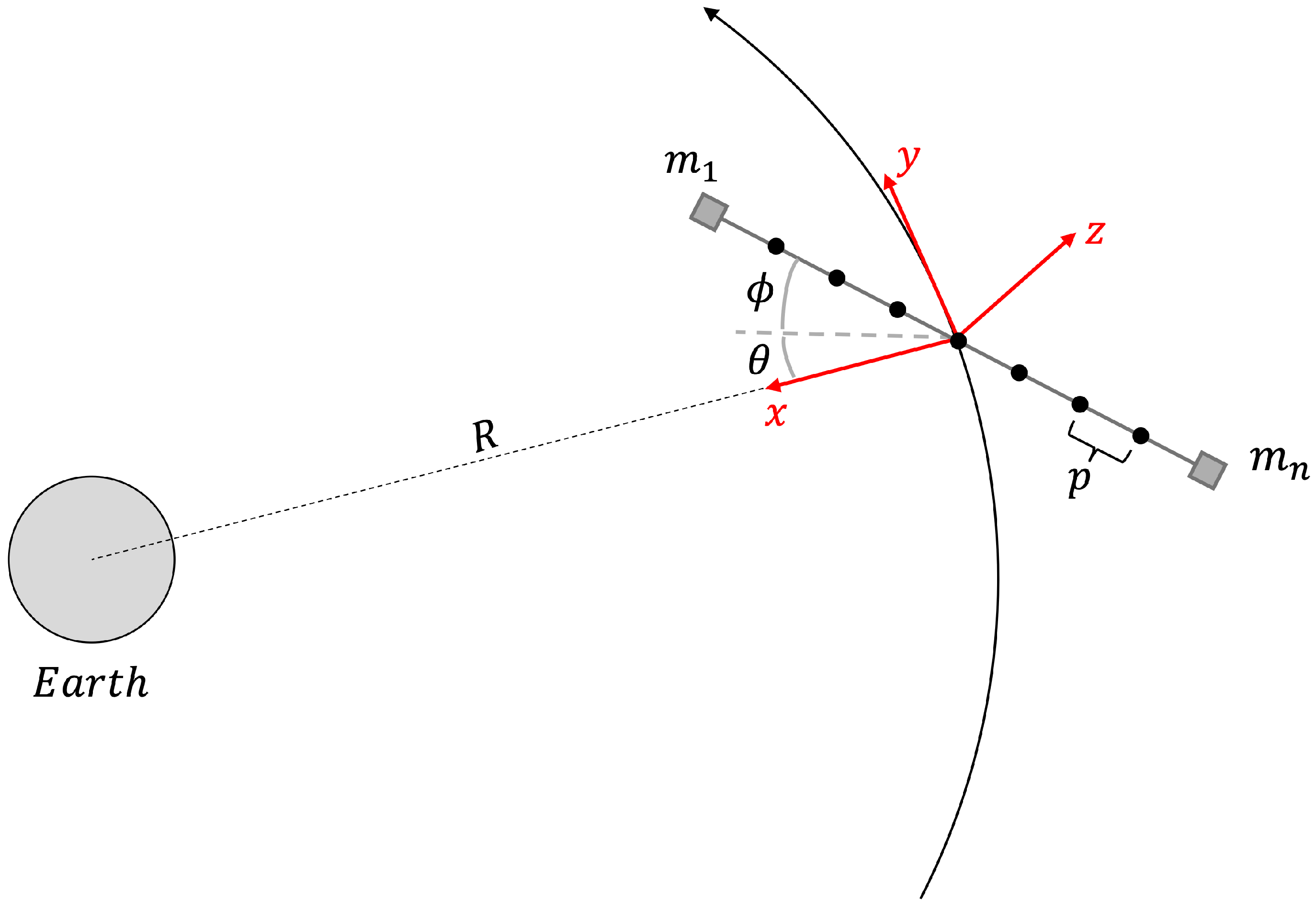
Figure 1. Basic representation of the tethered spinning system using the barbell chain model.
Remotesensing 18 00706 g001
Figure 2. Tether discretization with lumped masses and angles that define the orientation of each segment in the orbital plane.
Remotesensing 18 00706 g002
Figure 3. Difference of consecutive in-plane segment angles across the tethered system masses over time.
Remotesensing 18 00706 g003
Figure 4. Distances between two consecutive masses over time.
Remotesensing 18 00706 g004
Figure 5. Configuration with the spin axis lying on the orbital plane. The tether motion generates baseline projections both along and across the orbital velocity direction, allowing dual-direction sensing but slower baseline variation along the orbit.
Remotesensing 18 00706 g005
Figure 6. Configuration with the spin axis perpendicular to the orbital plane. The tether rotates within the orbital plane, leading to baseline variations only along the velocity direction and more frequent repetitions of the maximum baseline length.
Remotesensing 18 00706 g006
Figure 7. Vertical resolution of a stereo camera as a function of the orbital height for different baseline values. The section of the diagram corresponding to the lower orbital altitudes is highlighted in red.
Remotesensing 18 00706 g007
Figure 8. Example of the altitude variation of the Lunar Reconnaissance Orbiter over time.
Remotesensing 18 00706 g008
Figure 9. Vertical resolution as a function of elapsed seconds compared with the altitude variations. The configuration of the barbell system with a 5 km tether, a spin rate of 0.1 rpm, and the spin axis perpendicular to the orbital plane has been used.
Remotesensing 18 00706 g009
Figure 10. Projection of the baseline as a function of the elapsed time and the spin velocity of the tether system. The plotted curves are relative to a system with the spin axis on the orbital plane and orbiting the Earth at an altitude of 400 km. A decrease in altitude only shifts the peak line upwards and the two folds trend leftwards due to the orbital period decrease.
Remotesensing 18 00706 g010
Figure 11. Projection of the baseline as a function of the elapsed time and the spin velocity of the tethered system. The plotted curves are relative to a system orbiting the Moon along the Lunar Reconnaissance Orbiter (LRO) trajectory with the spin axis perpendicular to the orbital plane.
Remotesensing 18 00706 g011
Figure 12. Cross-track and along-track spatial resolution of the system in a 400 km Earth orbit with a 1 km tether length and a spin rate of 0.1 rpm. The inset highlights a zoomed region showing the highest achievable resolution.
Remotesensing 18 00706 g012
Figure 13. Cross-track and along-track spatial resolution of the system in a 50 km Moon orbit with a 1 km tether length and a spin rate of 0.1 rpm. The inset highlights a zoomed region showing the highest achievable resolution.
Remotesensing 18 00706 g013
Figure 14. Cross-track and along-track spatial resolution of the system along the LRO trajectory with a 1 km tether length and a spin rate of 0.1 rpm with the spin axis on the orbital plane. The inset highlights a zoomed region showing the highest achievable resolution.
Remotesensing 18 00706 g014
Figure 15. Along-track spatial resolution of the system along the LRO trajectory for a 1 km tether length and a spin rate of 0.1 rpm, with the spin axis perpendicular to the orbital plane. Due to attitude constraints, no cross-track resolution is achievable. The right panel shows a zoomed region highlighting the higher-resolution regime at shorter wavelengths.
Remotesensing 18 00706 g015
Table 1. Fraction of orbital time (%) during which the system satisfies the spatial resolution requirement for each investigated configuration. The percentages represent the portion of the orbital period in which the instantaneous ground resolution remains below the threshold values of 50 m ( λ = 4.2 cm), 1000 m ( λ = 70 cm), and 15 km ( λ = 33 m). Results are reported separately for the cross-track (ct) and along-track (at) directions, considering both spin rates (0.1 rpm and 1 rpm) and orbit types (Earth 400 km, Moon 100 km, and Moon 50 km).
Wavelength
ω  [rpm] λ = 4.2 cm λ = 70 cm λ = 33 m
ctatctatctat
Earth—400 km186.3578.1384.0575.1443.2042.42
0.186.2377.7083.8975.4842.1641.30
Moon—100 km196.6192.8896.0491.9387.5176.65
0.196.5695.1996.0794.5287.5079.13
Moon—50 km198.3096.1298.0695.5093.7888.28
0.198.3297.1298.0396.7693.7289.67
Disclaimer/Publisher’s Note: The statements, opinions and data contained in all publications are solely those of the individual author(s) and contributor(s) and not of MDPI and/or the editor(s). MDPI and/or the editor(s) disclaim responsibility for any injury to people or property resulting from any ideas, methods, instructions or products referred to in the content.