1. Introduction
Infrared–visible image fusion (IVIF) aims to integrate thermal target saliency from infrared images with rich texture details from visible images, thereby producing a fused image that preserves target discriminability, structural consistency, and fine-detail clarity [
1,
2]. This task is important for applications such as nighttime surveillance, autonomous driving, and security perception. Infrared imaging is more robust to illumination variations and highlights salient targets, whereas visible imaging provides more natural textures, boundaries, and fine-grained scene structures. However, the substantial modality gaps in imaging mechanisms and data distributions between the two modalities make it difficult to enhance infrared saliency without degrading visible structural naturalness.
Before the widespread adoption of deep learning, many IVIF methods were developed in transform domains, including multi-scale decomposition, sparse representation, and wavelet-based frameworks [
3,
4]. These methods are interpretable and effective at explicitly separating coarse structural information from fine details, but they usually depend on handcrafted activity measures and manually designed fusion rules. As a result, their generalization is limited in complex cross-modal scenarios, especially when source images exhibit strong modality inconsistency, structural competition, or weak local textures.
Recent deep learning methods have shifted IVIF from handcrafted fusion rules to data-driven representation learning. Representative frameworks such as DenseFuse, FusionGAN, IFCNN, RFN-Nest, and U2Fusion demonstrate that deep networks can effectively learn complementary multimodal features [
5,
6,
7,
8,
9]. Despite recent progress, existing methods still suffer from over-smoothed textures and unstable structural reconstruction. Consequently, two recurring issues remain: weak high-frequency textures are prone to over-smoothing, and low-frequency discrepancies between modalities may accumulate into structural conflicts, causing local artifacts or unstable backgrounds.
In response to these challenges, recent studies have begun to combine frequency-domain decomposition with deep neural networks. Classical wavelet theory provides a natural multiresolution representation for separating low-frequency structure from high-frequency details [
3,
4], while wavelet-assisted deep frameworks further show that explicit frequency decomposition can improve detail preservation and representation controllability in low-level vision and image fusion [
10,
11,
12,
13,
14]. Nevertheless, existing frequency-aware methods still face several challenges: some use decomposition mainly as a preprocessing or auxiliary tool, some do not explicitly compensate for weak high-frequency responses during nonlinear transformations, and some still suffer from structural competition when low-frequency information is fused without adaptive conflict suppression.
From the perspective of information representation, these challenges are essentially associated with different optimization goals in different frequency bands. Low-frequency components mainly characterize global layout, luminance, and structural consistency, whereas high-frequency components mainly describe edges, textures, and fine-detail clarity. Therefore, a more effective solution is to explicitly separate these two information types and assign them differentiated fusion strategies. At the same time, the decomposition–reconstruction process should preserve stable information transmission; otherwise, frequency-domain modeling may introduce uncontrollable information loss and weaken fusion robustness.
Motivated by these observations, we develop RIF-Fuse as a residual-enhanced invertible frequency-domain fusion framework for infrared–visible image fusion. The proposed method explicitly separates structural and textural information through an invertible wavelet decomposition–reconstruction pipeline, enabling band-controllable optimization for different information components [
13,
14]. A residual-enhanced Haar frequency encoder is introduced in the high-frequency branch to stabilize weak texture responses and alleviate detail suppression during training. In addition, a band-aware differential fusion strategy is designed to suppress low-frequency structural conflicts while enhancing high-frequency edges and textures. Together with a two-stage training scheme, these components improve optimization stability and cross-scene robustness.
The main contributions of this work are summarized as follows:
Band-controllable explicit decomposition interface. We construct a wavelet decomposition and reconstruction pipeline to explicitly represent structural (low-frequency) and textural (high-frequency) components while maintaining stable information transmission.
Residual-enhanced high-frequency modeling. A Haar residual enhancement mechanism is introduced in the high-frequency pathway to stabilize weak texture responses and alleviate detail suppression caused by smoothing bias.
Band-aware differential fusion strategy. Subband-level fusion rules are designed to suppress structural conflicts in low-frequency components while enhancing edges and textures in high-frequency components.
The remainder of this paper is organized as follows.
Section 2 reviews the related work on infrared–visible image fusion.
Section 3 presents the proposed RIF-Fuse framework in detail.
Section 4 describes the experimental settings and analyzes the results.
Section 5 discusses the limitations. Finally,
Section 6 concludes the paper.
2. Materials
This section reviews representative studies on infrared–visible image fusion (IVIF) from both traditional transform-domain and deep learning perspectives. To better position the proposed framework, we organize the discussion into four directions: traditional transform-domain methods, end-to-end unified fusion, structured cross-modality modeling, and frequency-aware/global modeling. These directions mainly differ in how complementary infrared and visible information is decomposed, selected, and preserved.
2.1. Traditional Transform-Domain Foundations
Before the deep learning era, many IVIF methods were built on transform-domain representations, including multi-scale transforms, sparse representation, and wavelet-based decomposition frameworks [
3,
4]. These methods separate low-frequency approximation components from high-frequency detail components, providing good interpretability and a clear basis for fusion-rule design. In this paradigm, low-frequency coefficients are usually used to preserve global luminance and structural information, whereas high-frequency coefficients are selectively combined to enhance edges and textures.
Despite their interpretability, traditional transform-domain methods usually rely on handcrafted activity measures and manually designed coefficient-selection strategies. As a result, their adaptability is limited when source images exhibit strong modality discrepancy, weak local textures, or complex target–background interactions. In addition, although classical wavelet decomposition provides a useful prior for distinguishing structural and textural information, most traditional methods cannot learn data-driven cross-modal interactions and therefore may struggle to maintain a satisfactory balance between thermal saliency and natural texture preservation in challenging scenes. These limitations motivate the development of learnable fusion frameworks while also indicating that explicit transform-domain priors remain valuable.
2.2. End-to-End Unified Fusion
End-to-end frameworks typically adopt an encode–fuse–decode pipeline and learn fusion mappings under unsupervised or weakly supervised objectives, such as reconstruction consistency, intensity preservation, and gradient constraints. Early representative methods perform fusion and reconstruction in a unified feature space, including DenseFuse, IFCNN, U2Fusion, RFN-Nest, and GAN-based fusion frameworks [
5,
7,
9,
15,
16]. These methods demonstrate that deep neural networks can effectively learn complementary representations from multimodal inputs without relying on handcrafted fusion rules, and they establish the basic paradigm of modern infrared–visible image fusion. Their main advantage lies in the simplicity of the overall framework: fusion can be achieved in a fully data-driven manner without requiring manually designed transform-domain operations or heuristic selection rules.
More recent studies further improve fusion performance by designing stronger fusion modules and training strategies. For instance, EMMA, DAFusion, and MaeFuse enhance cross-modality interaction and feature alignment through improved architectures or supervision mechanisms [
17,
18,
19]. These methods usually aim to strengthen feature extraction, improve cross-modal information exchange, or increase robustness under more challenging imaging conditions. As a result, they often achieve stronger performance on benchmark datasets and show better generalization than earlier unified fusion models. Nevertheless, despite steady progress, unified spatial-domain representations still have to satisfy structural consistency and detail fidelity simultaneously within a shared optimization space. In complex scenes, structural components tend to dominate optimization due to their higher statistical stability, making weak high-frequency textures more prone to over-smoothing during reconstruction.
2.3. Structured Modeling with Cross-Modality Interaction
Several recent methods have been employed in an attempt to mitigate the limitations of plain unified fusion by explicitly introducing structured interaction between infrared and visible modalities. Representative strategies include dual-branch extraction, cross-attention, iterative feature exchange, and decomposition-guided feature aggregation [
17,
18,
19,
20,
21,
22]. Compared with purely unified fusion pipelines, these methods improve the ability of the network to selectively preserve complementary information by modeling modality-specific features and their interactions more explicitly.
Such designs are particularly useful when thermal saliency and visible structural fidelity need to be preserved simultaneously. By introducing cross-modality interaction modules, the network can better align informative responses between the two modalities and reduce the risk that one modality excessively dominates the fusion result. However, most of these methods still perform interaction and reconstruction primarily in the spatial domain. Although they improve feature selection and information exchange, they do not always provide a clear interface for separating structural and textural information. As a result, low-frequency structural consistency and high-frequency detail preservation are still jointly optimized within a shared feature space, which may leave residual structural conflicts or detail attenuation unresolved.
2.4. Frequency-Domain Fusion and Global Modeling with External Priors
To improve interpretability and controllability, an increasing number of studies have turned to frequency-domain or wavelet-assisted fusion frameworks. Classical wavelet theory provides a natural multi-scale representation in which low-frequency subbands mainly encode global structure and luminance, whereas high-frequency subbands describe directional edges and textures [
3,
4]. This decomposition is particularly appealing for IVIF because the fusion requirements of structure and detail are inherently different across modalities. Some recent deep learning-based methods have therefore incorporated wavelet transforms as transform-domain interfaces, decomposition tools, or enhancement pathways, aiming to combine the interpretability of classical decomposition with the representational power of neural networks [
11,
12,
13,
14].
These frequency-aware methods indicate that explicit subband decomposition can alleviate some drawbacks of purely spatial-domain fusion. However, several challenges remain. First, in some frameworks, frequency decomposition mainly serves as a preprocessing or auxiliary representation step without sufficiently modeling the distinct semantic roles of low- and high-frequency subbands throughout the fusion pipeline. Second, weak high-frequency textures may still be attenuated during nonlinear feature transformations if no explicit compensation mechanism is introduced. Third, low-frequency fusion may still suffer from structural competition between modalities when global information is directly combined without adaptive conflict suppression. Therefore, simply introducing wavelet decomposition does not by itself guarantee controllable structure–detail coordination.
With the increasing adoption of transformer architectures in low-level vision tasks, fusion methods have also begun to incorporate stronger global modeling capabilities to capture long-range dependencies and improve cross-region consistency. Hierarchical vision transformers such as Swin Transformer [
20] and dynamic transformer architectures such as YDTR [
21] have been applied to infrared–visible image fusion to enhance global information aggregation. Efficient transformer-based restoration networks such as Restormer are also frequently adopted as backbone modules to balance global interaction and local representation [
22,
23]. Compared with conventional convolution-dominated frameworks, these architectures provide a larger receptive field and stronger contextual modeling ability, which is particularly useful in scenes where target saliency, background consistency, and long-range structural relations need to be jointly considered.
Beyond backbone improvements, incorporating external supervision and pretrained priors has become an important research direction. For instance, MetaFusion integrates fusion learning with object detection tasks to exploit task-driven gradients for guiding fusion [
24]. Similarly, MaeFuse leverages representations from masked autoencoder pretraining to enhance feature extraction and cross-domain generalization [
19]. These approaches indicate that fusion quality can be improved not only by modifying network structure but also by introducing stronger semantic or task-level guidance.
Different from existing unified, structured, or wavelet-assisted methods, the proposed RIF-Fuse is designed as a residual-enhanced invertible frequency-domain framework. It explicitly assigns different semantic roles to low-frequency and high-frequency components, introduces a residual enhancement path to compensate for weak texture responses in the high-frequency branch, and adopts a band-aware differential fusion strategy to address the distinct requirements of structural and detail subbands. In this way, our method aims to provide a more interpretable and controllable fusion mechanism while maintaining faithful information transmission through invertible decomposition and reconstruction.
3. Method
3.1. Framework Overview
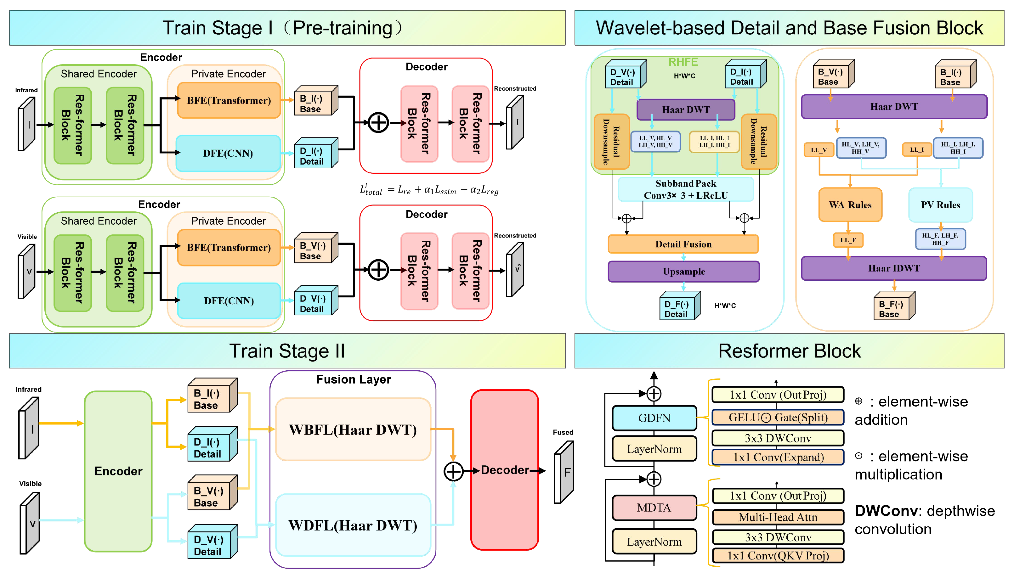
As illustrated in
Figure 1, we propose RIF-Fuse, a decompose–band-wise fuse–reconstruct framework for infrared–visible image fusion. Given a paired infrared image
I and a visible image
V, the objective is to generate a fused image
F that preserves the natural textures and fine details of the visible modality while injecting salient infrared targets, meanwhile avoiding structural conflicts and artifacts caused by modality discrepancies. Different from directly fusing features in the spatial domain, RIF-Fuse explicitly assigns two semantic roles to the latent representation: base (structural base) and detail (textural detail). This explicit division is motivated by the observation that low-frequency and high-frequency information play different roles in multimodal fusion and therefore should not be optimized under exactly the same fusion mechanism. An encoder is first used to extract and decompose features for both modalities:
Here, B represents relatively low-frequency information, such as global structure and luminance, while D captures relatively high-frequency variations, such as edges and textures.
After obtaining base and detail representations, band-wise fusion is performed:
Finally, a decoder reconstructs the fused image:
The motivation for performing fusion in a frequency-aware manner is that band decomposition explicitly exposes the hierarchy of low- and high-frequency components. Low-frequency components are more closely related to global layout, luminance consistency, and structural stability, whereas high-frequency components primarily correspond to edges, local contrast transitions, and fine textures. Therefore, the design principle of RIF-Fuse can be summarized as stabilizing low-frequency structures while sharpening high-frequency details. By decoupling these two information types and assigning them different fusion strategies, the proposed framework provides a more controllable solution to the trade-off between structural consistency and detail fidelity.
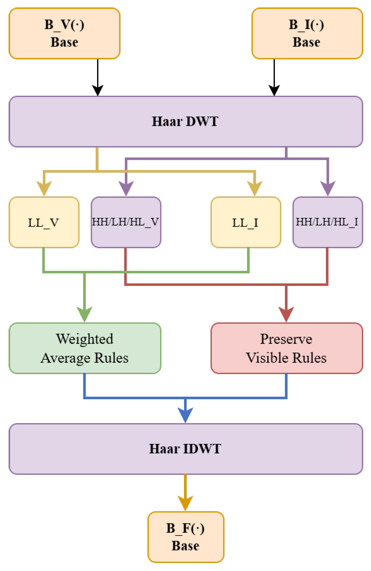
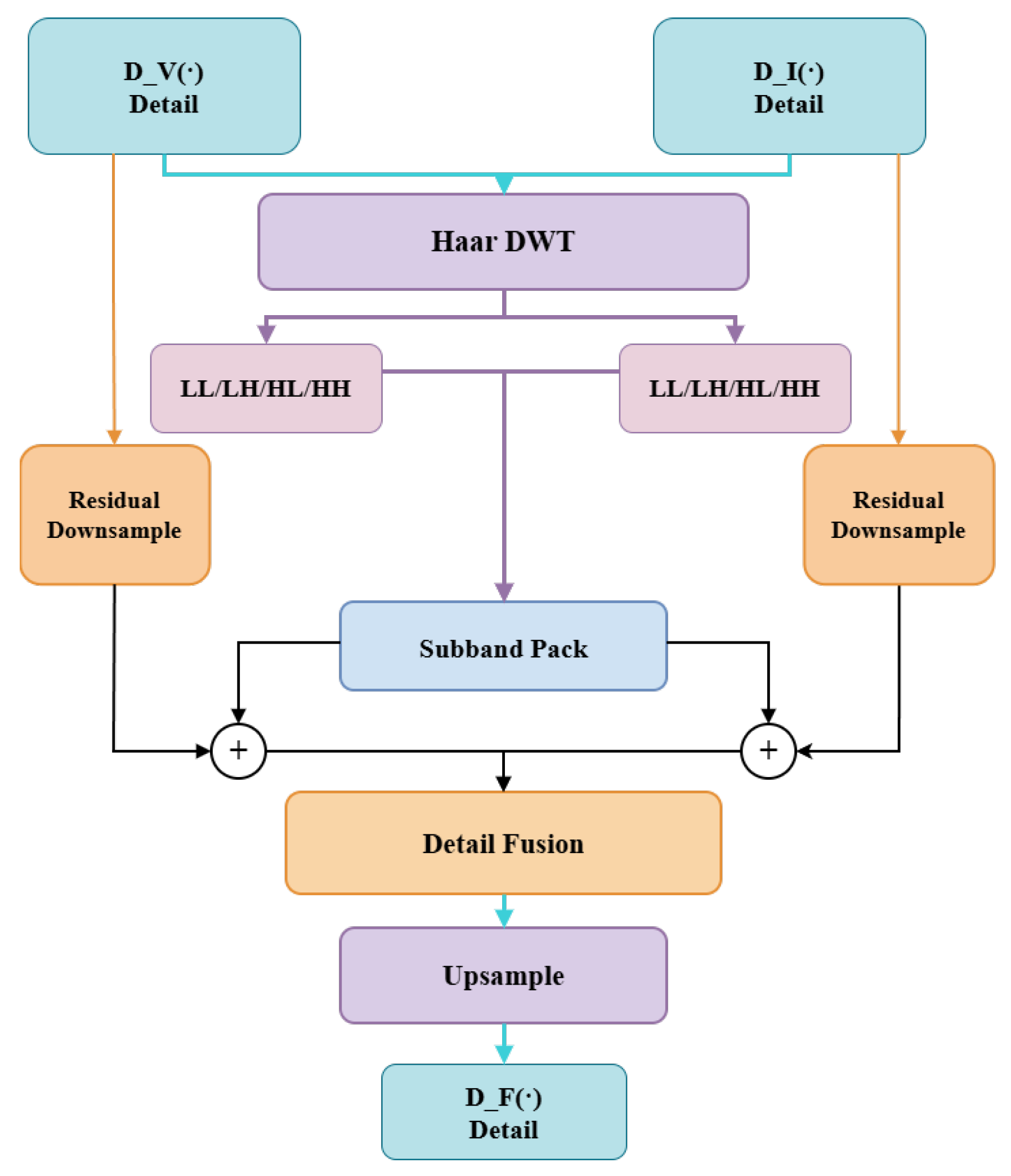
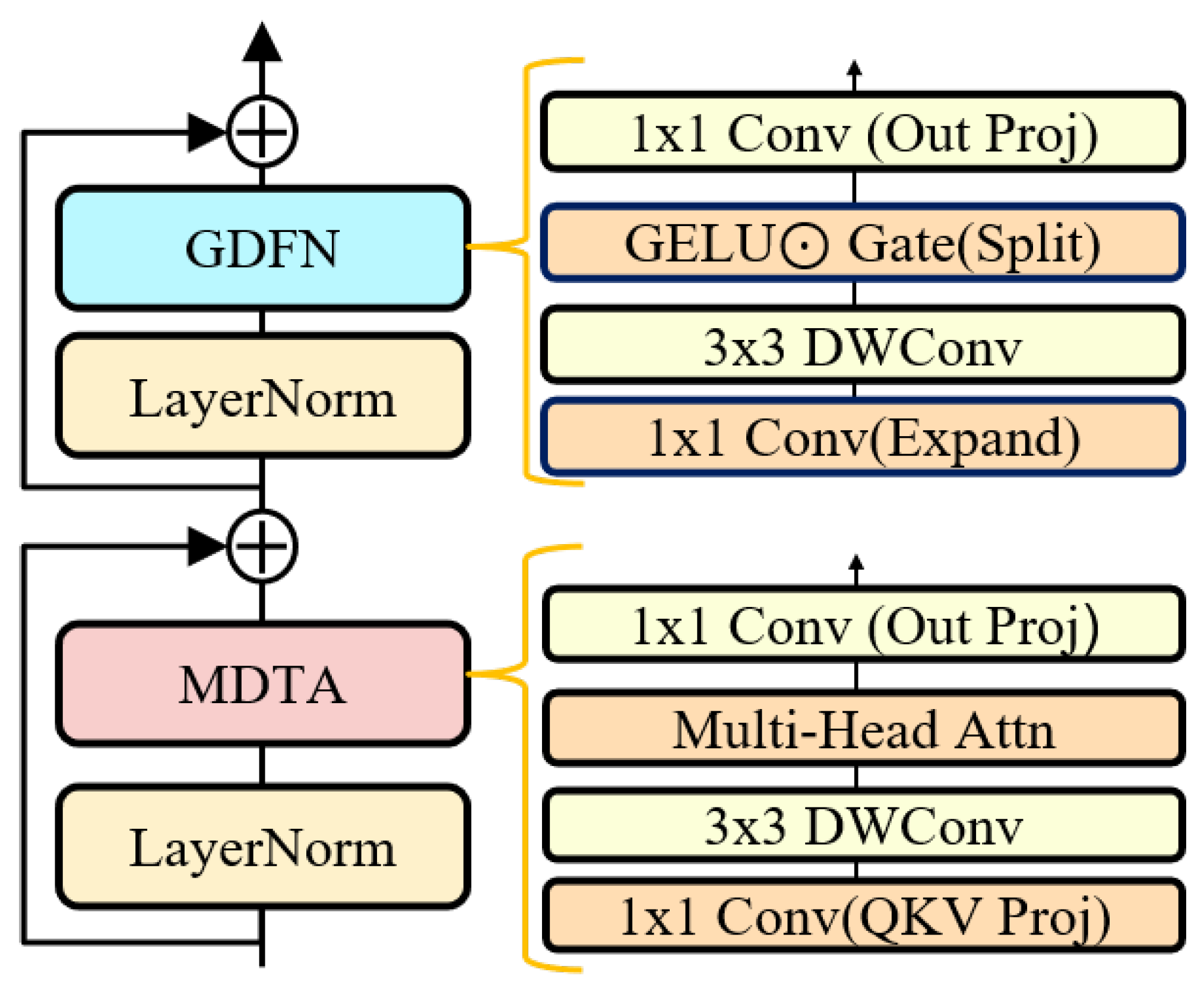
For clarity, the detailed structures of the base fusion module, the detail fusion module, and the transformer-based encoder–decoder backbone are illustrated in
Figure 2,
Figure 3 and
Figure 4, respectively.
Figure 2 presents the wavelet-based base fusion process,
Figure 3 shows the residual-enhanced detail fusion process, and
Figure 4 depicts the internal structure of the Resformer block used in the backbone.
3.2. Two-Stage Training Strategy
In infrared–visible image fusion tasks, a ground-truth fused image is typically unavailable as supervision. Directly training decomposition, fusion, and reconstruction simultaneously may cause unstable optimization in early stages [
25]. Therefore, we adopt a two-stage training strategy.
The strategy is motivated by the need to decouple representation stabilization from fusion learning. In the early training stage, if decomposition, subband fusion, and image reconstruction are optimized all at once, the encoder may not yet provide sufficiently stable base–detail representations, which in turn makes the subsequent fusion modules harder to optimize. We therefore first establish a reliable decomposition space and then introduce fusion-specific learning on top of it. This staged design improves optimization stability and makes the role of each module more explicit during training.
3.2.1. Stage I: Decomposition Pretraining
The first stage aims to learn stable base–detail representations. For an input image
,
The training objective is defined as
where
denotes the pixel reconstruction loss,
enforces structural similarity, and
represents a regularization term.
During this stage, only the encoder and decoder parameters are updated, while all fusion-related modules remain frozen. In our implementation, Stage I corresponds to the first 20 training epochs. This phase encourages the encoder to produce stable base and detail representations for each modality before introducing cross-modal fusion, thereby reducing optimization interference from the fusion layers.
3.2.2. Stage II: Fusion Training
After stable decomposition is obtained, fusion layers are introduced and the entire network is jointly optimized. This stage enables decomposed representations and fusion strategies to co-evolve under the fusion objective, improving training stability and final fusion performance.
More specifically, the pretrained encoder first extracts modality-specific base and detail features from the infrared and visible inputs. The base fusion module and the detail fusion module are then activated to generate fused subband representations, which are finally decoded into the fused image. In this stage, the fusion objective is combined with the decomposition regularization term so that the network can improve fusion quality while preserving the desired structure–detail separation behavior learned in Stage I.
In our implementation, Stage II starts after the decomposition pretraining stage and occupies the remaining 30 epochs. At this stage, the encoder, decoder, base fusion module, and detail fusion module are jointly optimized in an end-to-end manner. The learning rate is set to in Stage I and reduced to in Stage II, which further stabilizes the transition from representation learning to fusion-oriented optimization.
From an optimization perspective, this two-stage strategy serves two purposes. First, it prevents the decomposition process from being dominated by premature fusion gradients before meaningful base–detail semantics are formed. Second, once a stable decomposition basis is obtained, the fusion modules can focus on learning how to coordinate low-frequency structural information and high-frequency detail information more effectively. Therefore, the two-stage design is not merely a training heuristic but an integral part of the proposed frequency-aware fusion framework.
3.3. Wavelet-Based Frequency Fusion
To explicitly model frequency-domain information, Haar wavelet transform is adopted to perform discrete wavelet decomposition (DWT) and reconstruction (IDWT) [
3,
4]. For an input feature map
, DWT decomposes it into four subbands:
where
denotes the low-frequency approximation component, while
,
, and
represent directional high-frequency detail components. The inverse transform reconstructs the feature map:
We adopt the Haar wavelet because it is simple, orthogonal, computationally lightweight, and easy to integrate into an invertible decomposition–reconstruction pipeline. Moreover, one-level Haar decomposition directly produces one low-frequency approximation subband and three directional high-frequency detail subbands, which is well aligned with our objective of explicitly separating structural and textural information while keeping the frequency-domain transformation overhead low.
This decomposition naturally separates structural information (low frequency) from textural information (high frequency), which allows different fusion strategies to be assigned to different semantic roles. In RIF-Fuse, the base branch is designed to maintain low-frequency structural consistency and suppress cross-modal conflicts, whereas the detail branch focuses on preserving and enhancing high-frequency edges and textures.
3.3.1. Base Fusion
As shown in
Figure 2, the base branch first decomposes modality-specific base features into wavelet subbands and then performs band-aware fusion to preserve structural consistency while suppressing low-frequency conflicts. The base branch aims to preserve structural consistency while reducing low-frequency conflicts between modalities. Given base features
wavelet decomposition is first applied:
Since low-frequency subbands mainly determine global structure and luminance distribution, they are fused adaptively:
where
is a learnable weighting coefficient and ⊙ denotes element-wise multiplication.
The weighting network is implemented as a lightweight two-layer convolutional module. Specifically, the concatenated low-frequency feature is first projected from channels to C channels by a convolution, followed by batch normalization and a ReLU activation. A second convolution is then used to generate the final weighting map, and a sigmoid activation constrains to the range . This design allows the network to adaptively emphasize the more reliable structural response at each location while maintaining low computational overhead. The weighting network is jointly optimized with the full model in an end-to-end manner rather than being trained separately.
For the high-frequency subbands in the base branch, the modality with stronger directional response is preferentially preserved:
where
denotes a response-guided selection rule for detail inheritance.
The fused base feature is reconstructed by IDWT:
The rationale behind this design is that low-frequency inconsistencies between infrared and visible modalities are one of the main causes of structural competition and background instability. Therefore, low-frequency fusion is handled by adaptive weighting rather than direct averaging, while high-frequency directional responses are selectively inherited to preserve structure-related details without introducing excessive smoothing.
3.3.2. Detail Fusion
Figure 3 illustrates the detail fusion branch. The detail branch aims to preserve edges and textures while avoiding discontinuous switching between modalities. Given detail features
wavelet decomposition is first applied:
Subbands are packed along the channel dimension:
A lightweight convolutional encoder generates frequency representations:
To improve detail preservation, a residual bypass is introduced:
The residual-enhanced representation becomes:
Before the residual addition in Equation (
18), the two branches are projected to the same feature size. The encoded frequency representation
is obtained from the packed wavelet subbands and mapped to the target feature dimension, while the residual branch
applies a strided convolutional projection to
so that
has the same spatial resolution and channel number as
. Therefore, the residual addition is performed after dimensional alignment, which ensures that the operation in Equation (
18) is well defined.
Finally, cross-modality fusion is performed:
The fused detail feature is then upsampled to the original resolution:
Compared with direct spatial-domain concatenation, this design provides two advantages. First, the wavelet decomposition exposes directional high-frequency responses, which makes texture-related fusion more structured and controllable. Second, the residual enhancement path compensates for weak high-frequency responses that may otherwise be suppressed during nonlinear feature transformation, thereby improving edge continuity and fine-detail preservation in the reconstructed fused image.
3.4. Transformer-Based Encoder–Decoder Backbone
To enhance long-range dependency modeling and improve global context aggregation, we adopt a transformer-based encoder–decoder backbone in the proposed framework. Compared with purely convolutional designs, transformer-based blocks are more effective in capturing long-range contextual interactions, which is beneficial for infrared–visible image fusion, where target saliency, structural consistency, and background coherence often depend on both local details and nonlocal contextual relations. The overall backbone is illustrated in
Figure 4.
The encoder first projects the input image into a latent feature space
where
denotes the shallow embedding layer. The encoded feature is then processed by stacked transformer blocks to extract hierarchical contextual representations
where
denotes the encoder.
In the current implementation, the encoder contains 4 transformer blocks and the decoder also contains 4 transformer blocks. This configuration is adopted to balance representation capacity and computational efficiency.
The decoder reconstructs the feature representation after base–detail fusion,
where
denotes the fused latent representation and
denotes the decoder. Finally, the output layer maps the decoded feature to the fused image:
As shown in
Figure 4, each transformer block consists of a normalization layer, a multi-head self-attention module, and a feed-forward module, together with residual connections between adjacent sublayers. This design enables the backbone to jointly model global interactions and local feature refinement within a unified architecture.
From the perspective of representation learning, introducing transformer blocks into the encoder–decoder offers two advantages. First, the global receptive field helps to preserve scene-level structural consistency during reconstruction, which is particularly important when the infrared and visible modalities contain different but spatially correlated salient responses. Second, contextual aggregation makes the fused representation less dependent on purely local decisions, thereby reducing the risk of discontinuous structures or locally inconsistent textures.
The transformer-based backbone does not directly replace the role of frequency decomposition; rather, it complements the proposed frequency-aware fusion pipeline. The wavelet-guided base and detail branches explicitly regulate what kind of information should be preserved and fused, while the transformer-based encoder–decoder provides stronger contextual modeling for encoding and reconstruction. In this way, explicit frequency decomposition and global context modeling are integrated into a unified framework.
3.5. Method Summary
In summary, RIF-Fuse first establishes stable base–detail decomposition through a two-stage training strategy. Wavelet-based frequency-domain modules are then introduced to perform band-wise fusion.
Low-frequency components emphasize structural consistency and conflict suppression, while high-frequency components focus on preserving edges and textures. The residual-enhanced frequency encoder further stabilizes high-frequency representations.
By integrating invertible wavelet decomposition, band-aware fusion strategies, and residual enhancement mechanisms, RIF-Fuse achieves a better balance between structural stability and detail fidelity in infrared–visible image fusion.
Additional experimental results and supplementary visual comparisons are provided in
Appendix A.
4. Experiments
This section provides a systematic evaluation of the proposed residual-enhanced invertible frequency-domain fusion framework, namely RIF-Fuse. Since infrared–visible image fusion lacks a unique ground-truth fused image for supervision and evaluation, a single dataset or metric cannot fully reflect the overall performance of a fusion method. Therefore, we adopt an experimental protocol combining cross-dataset evaluation, multiple quantitative metrics, ablation studies, and qualitative visual comparisons.
Specifically, the model is trained on the MSRS dataset [
26] and evaluated on the TNO [
27] and RoadScene [
28] datasets. Quantitative evaluation uses multiple complementary metrics reflecting information content, structural preservation, and detail strength.
4.1. Training and Testing Settings
We adopt a source-domain training and cross-domain testing protocol. The model is trained on the MSRS dataset, while testing is conducted on TNO and RoadScene. This setting better reflects real-world deployment scenarios where the training distribution differs from the testing environment.
The proposed method is implemented in PyTorch. Training follows the two-stage strategy described in
Section 3.
During Stage I, only the encoder and decoder are updated to establish stable base–detail representations, while all fusion-related modules remain frozen. During Stage II, the base fusion module, the detail fusion module, and the frequency-domain fusion modules are activated, and the entire network is jointly optimized. This setting makes the training schedule more consistent with the functional decomposition of the proposed framework.
The model is trained for 50 epochs with batch size 16. The first 20 epochs are used for decomposition pretraining, and the remaining 30 epochs are used for fusion training. The Adam optimizer is adopted with weight decay . The learning rate is set to in Stage I and in Stage II. A cosine annealing learning-rate schedule is applied during training.
In implementation, the Stage I optimization is restricted to representation learning so that the encoder can first provide stable base and detail features for each modality. After this decomposition space is established, Stage II introduces the fusion-related modules and jointly optimizes the full model under the fusion objective. This staged setting improves optimization stability and reduces the risk that premature fusion gradients disrupt the formation of meaningful frequency-aware representations.
For reproducibility, all models in the quantitative comparison are evaluated under the same preprocessing pipeline and the same evaluation scripts whenever possible. When official implementations are available, they are used directly; otherwise, the compared methods are reimplemented according to their original descriptions. This setting is intended to ensure a fair comparison under unified testing conditions.
We further evaluate the computational cost of the proposed framework. For an input size of , RIF-Fuse contains 1.64 M learnable parameters and requires 120.25 G FLOPs. The average inference time is 158.19 ms per image, corresponding to 6.32 FPS. The inference time is measured over 100 forward passes on an NVIDIA GeForce RTX 4090 GPU using PyTorch 2.1.2 with CUDA 12.1, and the FLOPs are computed using a standard PyTorch-based profiling tool.
4.2. Datasets
MSRS (Training Dataset). The MSRS dataset [
26] contains aligned infrared and visible image pairs collected from real-world road scenarios. It includes various conditions, such as nighttime scenes, pedestrians, vehicles, and complex backgrounds. We use MSRS as the training dataset.
TNO (Testing Dataset). The TNO dataset [
27] is a widely used benchmark in infrared–visible fusion research. It contains diverse scenes with different imaging conditions and is commonly used to evaluate robustness and generalization ability.
RoadScene (Testing Dataset). RoadScene [
28] focuses on road-centric scenarios containing vehicles, pedestrians, and buildings. The dataset emphasizes structural consistency and detail preservation, making it suitable for evaluating the practical usability of fusion algorithms.
4.3. Baselines
To comprehensively evaluate the proposed method, we compare RIF-Fuse with several representative infrared–visible fusion methods. These methods represent different design philosophies in the literature, including end-to-end unified fusion, explicit feature decomposition, global context modeling, cross-modality interaction, and robustness-oriented fusion design. By selecting baselines with diverse architectural characteristics, we aim to provide a more balanced comparison and to better analyze the strengths of the proposed framework from multiple perspectives.
Specifically, the compared methods include PIAFusion [
29], U2Fusion [
9], IGNet [
30], CDDFuse [
25], PFCFuse [
31], EMMA [
17], MaeFuse [
19], and DAFusion [
18]. PIAFusion and U2Fusion are representative end-to-end fusion methods and serve as important references for evaluating unified spatial-domain fusion behavior. IGNet provides an additional baseline for assessing feature interaction and reconstruction capability under infrared–visible fusion settings.
Among them, CDDFuse [
25] introduces correlation-driven dual-branch decomposition to explicitly separate shared and modality-specific components, which makes it a strong baseline for structured representation learning. PFCFuse [
31] integrates PoolFormer and CNN modules to improve global context modeling while maintaining local feature extraction ability. EMMA [
17] enhances cross-modality interaction through equivariant feature alignment and is therefore particularly relevant for evaluating whether stronger feature communication can improve fusion quality.
We also include two recent approaches, MaeFuse [
19] and DAFusion [
18]. MaeFuse leverages masked autoencoder pretraining to improve representation learning and cross-domain generalization, while DAFusion focuses on robustness under distribution shifts and degraded imaging conditions. Together, these methods provide competitive and representative baselines for evaluating the proposed RIF-Fuse framework under both general and challenging scenarios.
Whenever possible, official implementations are used. Otherwise, methods are reimplemented following the original papers. All models are evaluated under the same preprocessing pipeline and evaluation scripts to ensure fair comparison. In addition, the corresponding reference numbers of the compared methods are explicitly given in
Table 1,
Table 2,
Table 3,
Table 4,
Table 5 and
Table 6 for easier cross-checking with the original literature.
4.4. Evaluation Metrics
Fusion quality cannot be fully described by a single metric. Therefore, we employ seven widely used metrics to evaluate different aspects of fusion performance.
These metrics collectively measure information richness, structural preservation, and detail representation. Additional experimental results and supplementary visual comparisons are provided in
Appendix B.
4.5. Quantitative Comparison
Table 1 and
Table 2 report the quantitative comparison results on the TNO and RoadScene datasets. Overall, RIF-Fuse achieves competitive performance across multiple complementary metrics and shows a favorable balance between structural stability and detail preservation. Since different metrics emphasize different aspects of fusion quality, the quantitative results should be interpreted jointly rather than through any single indicator alone.
On the TNO dataset, the proposed method achieves the best performance in EN, SF, and MI while remaining competitive in SD, VIF, and . The improvement in EN suggests that the fused images contain richer overall information, whereas the highest SF indicates stronger edge and texture activity. The strong MI score further shows that complementary information from both modalities is effectively retained in the fused result. Although CDDFuse and MaeFuse perform well on some perceptual or structure-related metrics, RIF-Fuse exhibits a more favorable balance among information richness, detail activity, and source-information retention, which is consistent with the design objective of jointly preserving thermal saliency and visible fine structures.
On the RoadScene dataset, the advantage of RIF-Fuse becomes more evident. The proposed method achieves the best values in EN, SD, and SF and reaches a competitive level in SCD. In particular, the improvements in SD and SF indicate that the fused images have stronger contrast variation and more active high-frequency responses, which is desirable for road scenes containing boundaries, vehicles, pedestrians, and other structurally rich objects. Although some compared methods obtain higher values on certain individual metrics, such as MI or VIF, RIF-Fuse consistently performs strongly on the metrics most closely related to contrast enhancement, structural expressiveness, and detail clarity. Since RoadScene contains more complex scene structures, such as vehicles and road boundaries, these results indicate that the proposed framework can maintain both structural consistency and detail clarity in challenging scenarios.
In summary, the quantitative results on both datasets suggest that the proposed invertible frequency decomposition and band-aware fusion strategy contribute to improved information richness and detail representation while maintaining competitive structural consistency. This trend is particularly evident on RoadScene, where the scene complexity places higher demands on both contrast preservation and texture reconstruction.
4.6. Prior Verification
To investigate whether the advantage of the proposed framework mainly comes from frequency-domain representation rather than handcrafted cues, we compare several representative priors, including Canny, GRE, and HOG, with the wavelet-based decomposition baseline IDWT.
For a fair comparison, these priors are used as alternative front-end representations under the same evaluation protocol, and their outputs are assessed using the same quantitative metrics on the TNO and RoadScene datasets. In this verification experiment, Canny is used to emphasize edge responses, GRE is adopted to enhance local gradient-related structures, HOG is employed to characterize orientation-sensitive local patterns, and IDWT serves as a frequency-domain decomposition baseline. This comparison aims to determine whether the advantage of the proposed framework arises mainly from frequency-aware representation rather than handcrafted local cues.
From
Table 3 and
Table 4, handcrafted priors can strengthen certain local responses but usually perform well only on specific metrics. For example, Canny produces strong SF values due to its edge-enhancement property, while GRE or HOG may improve certain structure-related statistics under specific scenes. However, these priors lack a unified representation mechanism for simultaneously preserving structure and detail.
Compared with the handcrafted priors, IDWT shows more favorable overall behavior on several structure- and information-related metrics, although it is not uniformly the best on every single indicator. On the TNO dataset, IDWT achieves the highest SD, MI, SCD, and VIF among the compared priors. On the RoadScene dataset, IDWT is also clearly stronger in SD, MI, and VIF, while the handcrafted priors exhibit relatively better values on some other individual metrics, such as SF or SCD. Therefore, rather than claiming uniformly more stable performance, these results more accurately indicate that frequency-domain decomposition provides a more balanced and systematic representation for preserving both global structure and complementary source information.
This observation aligns with the design rationale of RIF-Fuse. Handcrafted priors are usually specialized for enhancing certain local patterns, such as gradients or edge responses, but they do not explicitly provide a unified decomposition interface for jointly regulating low-frequency structural information and high-frequency detail information. In contrast, wavelet-based decomposition offers a more structured multi-scale representation, which is better aligned with the fusion objective of simultaneously preserving structural consistency and detail fidelity.
4.7. Ablation Study
To analyze the contribution of each component, we conduct ablation studies on the TNO and RoadScene datasets. The ablation is organized around the main modules of the proposed framework, including the wavelet-based decomposition baseline, the band-aware fusion strategy, the Haar-based high-frequency modeling pathway, and the residual enhancement mechanism in the detail branch.
For clarity, the evaluated configurations are defined as follows: IDWT denotes the wavelet-based decomposition baseline; BA denotes the band-aware fusion strategy; IDWT + Haar denotes the model with wavelet decomposition and the Haar-based high-frequency pathway; IDWT+BA combines the decomposition baseline with the band-aware fusion strategy; and RIF-Fuse denotes the complete model. In addition, to more explicitly isolate the contribution of the residual compensation mechanism, we further introduce a “
w/
o Residual Enhancement” configuration (abbreviated as “
w/
o res-enhance” in
Table 5 and
Table 6), in which the residual bypass in the high-frequency branch is removed while the Haar-based decomposition pathway is retained.
This additional configuration is necessary because the previously reported IDWT + Haar setting verifies the effect of introducing the Haar-based detail branch, but it does not fully isolate the contribution of the residual bypass itself.
First, comparing IDWT with BA shows that band-aware fusion improves EN and SF on both datasets, indicating that differentiated treatment of low- and high-frequency components can effectively enhance information richness and edge activity. This trend suggests that explicitly assigning different fusion behaviors to structural and detail components is beneficial even before the full residual-enhanced framework is introduced.
Second, comparing IDWT with IDWT+Haar demonstrates the effect of introducing the Haar-based high-frequency pathway. The Haar branch improves EN and SF, especially on RoadScene, suggesting that additional frequency-aware detail modeling is helpful for preserving weak textures and strengthening local detail responses in more complex scenes.
A more direct comparison should be made between IDWT + Haar and “
w/
o res-enhance” since these two settings differ mainly in whether the residual compensation pathway is activated. From
Table 5 and
Table 6, the differences between these two configurations are relatively limited on several metrics, which indicates that the Haar-based high-frequency pathway already contributes substantially to detail modeling. Therefore, the residual enhancement branch should be interpreted as providing an additional but relatively modest refinement rather than a dominant performance gain by itself.
More specifically, on the TNO dataset, IDWT + Haar and “w/o res-enhance” exhibit very similar EN, SF, VIF, and values, while the differences in SD, MI, and SCD are also relatively small. This suggests that, in simpler scenes with cleaner backgrounds and more concentrated salient targets, the major benefit already comes from the Haar-based frequency-aware detail pathway, whereas the residual compensation mechanism mainly provides limited supplementary refinement. On the RoadScene dataset, the two configurations also remain close overall, but the full model still achieves the strongest joint performance in EN, SD, and SF. This suggests that the residual enhancement pathway does not dramatically change the performance trend by itself but can still provide a useful complement within the complete framework.
The metric changes in
Table 5 and
Table 6 also show that the proposed modules do not improve all the indicators simultaneously because different metrics emphasize different aspects of fusion quality. On the TNO dataset, introducing BA and Haar-related components significantly improves EN and SF, suggesting stronger information richness and more active edge/texture responses. However, SD, MI, and VIF decrease compared with the IDWT baseline. This phenomenon is closely related to the different representation characteristics of the compared configurations. As a pure wavelet-based decomposition baseline, IDWT preserves source-image statistics and subband information in a more direct manner, with relatively limited learned modulation after decomposition. Consequently, its fused outputs remain more strongly correlated with the original source distributions, which is advantageous for metrics such as SD, MI, and VIF, which are sensitive to intensity dispersion, source-information inheritance, and source-related perceptual fidelity. This tendency is particularly evident in relatively simple scenes, where the source structures are cleaner and the original statistical characteristics can be retained more directly. In contrast, the proposed modules do not aim to maximize direct statistical similarity to the source images. Instead, they introduce more adaptive fusion regulation by suppressing low-frequency structural competition and strengthening high-frequency detail modeling. Although this improves structure–detail coordination and enhances the expressive quality of the fused representation, it also reduces the degree to which the output directly follows the original source distributions. As a result, some metrics that favor stronger source-level statistical consistency may decrease, even when the fused image exhibits better structural organization and more informative detail representation. In contrast, the proposed modules more actively enhance high-frequency details and suppress structural conflicts, which improves detail expressiveness but may reduce direct statistical correlation with the source images.
On the RoadScene dataset, the behavior is slightly different. Although MI and VIF still decrease compared with IDWT, the full RIF-Fuse model achieves the highest SD together with the best EN and SF. This indicates that, in more structurally complex scenes, such as road environments containing boundaries, vehicles, and densely distributed textures, the proposed band-aware fusion and residual-enhanced detail modeling are more effective at strengthening contrast variation and structural expressiveness. Therefore, the ablation results suggest that the proposed framework favors a better balance between contrast/detail enhancement and source-information retention rather than uniformly maximizing every metric.
Finally, combining the above mechanisms in the full RIF-Fuse model leads to the strongest overall balance across the two datasets. On TNO, the full model achieves the best EN and SF while remaining competitive on the other metrics. On RoadScene, it achieves the best EN, SD, and SF, indicating that the proposed framework can jointly improve contrast, structural expressiveness, and detail clarity.
4.8. Qualitative Comparison
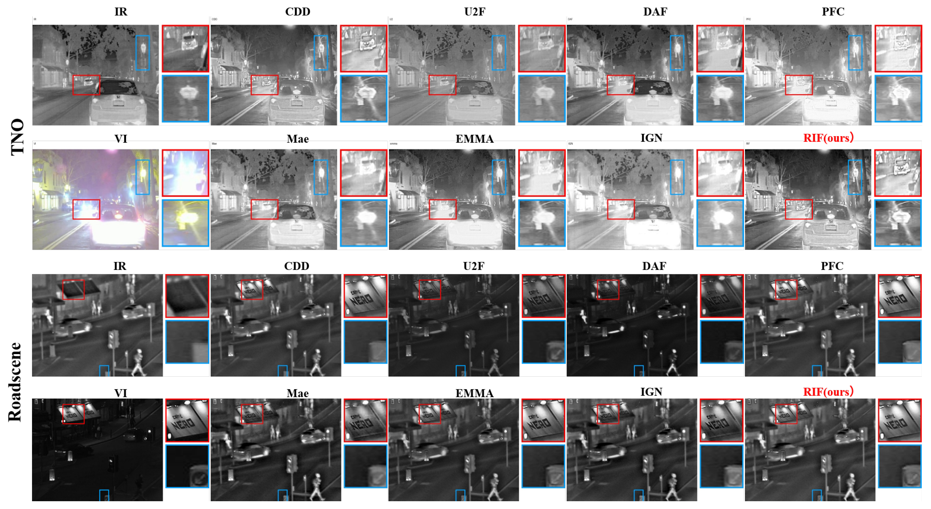
Figure 5 presents qualitative comparison results on the TNO and RoadScene datasets. Compared with competing methods, RIF-Fuse better preserves salient infrared targets while maintaining more natural visible textures and clearer structural boundaries.
More specifically, in regions containing weak targets or dark backgrounds, the proposed method highlights thermally salient objects more clearly without introducing severe background over-enhancement. At the same time, texture regions such as road boundaries, vehicle contours, and surrounding scene structures remain relatively sharp and continuous. This observation is consistent with the quantitative results: the strong SF and EN values correspond to better preservation of edge activity and information richness, while the competitive SCD values indicate that these improvements are achieved without obvious structural inconsistency.
In contrast, some comparison methods tend to overemphasize either infrared saliency or visible texture. The former may lead to unnatural local brightness or structural drift, whereas the latter may weaken target prominence. The visual results suggest that RIF-Fuse provides more balanced fusion behavior, which is consistent with the design principle of stabilizing low-frequency structures while enhancing high-frequency details.
5. Discussion
Although the proposed RIF-Fuse framework achieves competitive performance on multiple benchmarks, several limitations still remain and provide opportunities for further improvement.
First, the current framework mainly focuses on frequency-domain decomposition and local feature interaction. Although the transformer-based backbone introduces attention-based global modeling capability, long-range structural dependencies across distant regions may still be insufficiently captured in some complex scenes. In such cases, limited global interaction may restrict the ability of the model to maintain fully consistent structural relationships across the entire image. Recent sequence modeling approaches, such as state-space models (e.g., Mamba) [
39,
40], have demonstrated strong capability in capturing long-range dependencies with high computational efficiency. Integrating such mechanisms into the fusion framework may further improve global structural coordination while maintaining efficient inference.
Second, the proposed framework assumes that infrared and visible images are well aligned. In practical applications, however, slight misalignment or registration errors are often unavoidable due to sensor differences, viewpoint variations, and environmental disturbances. These spatial inconsistencies may affect the reliability of frequency-domain fusion, particularly when high-frequency components are directly combined, potentially leading to local artifacts or structural distortions in the fused results. To address this limitation, future research could explore robust fusion strategies that explicitly account for registration uncertainty. For example, incorporating lightweight alignment modules, spatial transformers, or deformable feature alignment mechanisms may help to improve the robustness of the fusion process under imperfect registration conditions.
Third, although wavelet-based decomposition provides an interpretable and computationally efficient frequency-domain representation, it may still impose certain limitations in modeling complex cross-modality relationships. Fixed wavelet filters may not fully adapt to diverse scene structures or modality-specific characteristics. Consequently, more flexible alternatives, such as learnable frequency transforms, adaptive multi-scale representations, or dynamic decomposition strategies, could further improve the representation capacity of the fusion framework.
Despite these limitations, the proposed band-aware fusion design provides a clear and interpretable mechanism for balancing structural consistency and detail preservation [
22].





 ,
,