Article

Spectrum Sharing Design for Integrated Aeronautical Communication and Radar System

1
School of Electronics and Information Engineering, Beihang University, Beijing 100191, China
2
State Key Laboratory of CNS/ATM, Beijing 100191, China
*
Author to whom correspondence should be addressed.
Remote Sens. 2025, 17(7), 1208; https://doi.org/10.3390/rs17071208
Submission received: 15 January 2025 / Revised: 25 March 2025 / Accepted: 26 March 2025 / Published: 28 March 2025

Abstract

:
The novel framework of an integrated aeronautical communication and radar system (IACRS) to realize spectrum sharing is investigated. A non-orthogonal multiple access (NOMA)-motivated multi-input–multi-output (MIMO) scheme is proposed for the dual-function system, which is able to detect multiple aircraft while simultaneously transmitting dedicated messages. Specifically, NOMA-inspired technology is utilized to enable dual-spectrum sharing. The superposition of communication and radar signals is facilitated in the power domain. Successive interference cancellation (SIC) is employed at the receiver to effectively mitigate inter-function interference. Subsequently, the regularity of the three-dimensional flight track and attitude is exploited to model the air-to-ground (A2G) MIMO channel. Based on this framework, a joint optimization problem is formulated to maximize the weighted achievable sum rate and the sensing signal–clutter–noise ratio (SCNR) while satisfying the rate requirements for message transmission and ensuring the radar detection threshold. An alternative optimization (AO) algorithm is proposed to solve the non-convex problem with highly coupled variables. The original problem is decoupled into two manageable subproblems: transmit beamforming of the ground base station combined with power allocation and receiver beamforming at the aircraft. The penalty-based approach and the successive rank-one constraint relaxation (SROCR) method are developed for iteratively handling the non-convex rank-one constraints in subproblems. Numerical simulations demonstrate that the proposed IACRS framework significantly outperforms benchmark schemes.

1. Introduction

To achieve safer and more efficient air traffic management (ATM), it is crucial to modernize the aeronautical communications system (ACS) [1]. A new promising ACS for cruise flight safety has emerged named the L-band digital aeronautical communication system (L-DACS). It is a next-generation air-to-ground (A2G) communication system designed to enhance aviation communication capacity and efficiency. L-DACS operates in the L-band spectrum, providing reliable data links to improve the operation efficiency of ATM, which can significantly improve the operation efficiency of ATM. Additionally, the L-DACS candidate system based on the orthogonal frequency division multiplexing (OFDM) physical-layer technique must be able to operate in the presence of interference from other pieces of equipment [2] and also cause the minimum possible interference to legacy systems, e.g., distance measuring equipment (DME) [3], in the same frequency band. This is particularly important since the current ATM system relies on the foundation infrastructure, communication, navigation, and surveillance (CNS), which provides critical functions for the safety of aircraft (AC). However, the availability of a dedicated frequency spectrum for CNS is struggling to keep up with the increasing saturation of the licensed aviation spectrum band, especially in congested airspace. Radar systems, used for navigation or surveillance function, have occupied a major portion of the spectrum for civilian aviation operations, leaving the usable spectrum for ACS scarce. Therefore, efficient spectrum utilization strategies are of paramount importance to enhance the performance of the integrated CNS system. A cost-efficient strategy for achieving high-quality CNS system performance is to leverage already-existing and available technologies such as multiple-input–multiple-output (MIMO). This can provide obvious advantages in terms of throughput and reliability by exploiting the spatial-domain channel correlation [4]. 3D beamforming is utilized for A2G communications with a phased uniform planar array (UPA) to realize a flexible coverage [5], enabling dynamic adjustment of beam patterns to match the target area’s geometry. Additionally, the sparsity of A2G communication channels can also benefit from MIMO [6], which exploits spatial diversity to solve the sparse recovery problem. Despite the evident merits of MIMO, the effective deployment of CNS is confronted with another challenge: the vulnerability of the A2G data link. This situation originates from the mutual interference induced by the presence of various pieces of avionics equipment. To address this issue, spectrum sharing between aeronautical communication and radar systems presents a promising solution [7], which has the potential to enable the utilization of additional spectrum resources for communication systems. Consequently, it remains crucial to continue enhancing the spectral efficiency (SE) in order to satisfy the stringent demands of future ACS. In this context, non-orthogonal multiple access (NOMA) has been recognized as a potentially effective technique for improving the SE as it allows for simultaneous multi-user transmission sharing the same resource block [8]. Specifically, the core principle of NOMA is to enable the access of multiple users within the same time–frequency resource blocks while differentiating them in the power domain. It improves spectral efficiency and system capacity by utilizing superposition coding (SC) at the transmitter and successive interference cancellation (SIC) at the receiver [9]. In contrast to the design of orthogonal multiple access (OMA), the NOMA-based framework can achieve higher SE as it serves multiple users in the same resource block, thereby significantly enhancing communication performance.

1.1. Related Works

In recent decades, research interest in communication and radar integration has increased, driven by the goal of suppressing mutual interference and enabling functional collaboration. Generally speaking, existing research on integration can be divided into two main categories: radar and communication coexistence (RCC) [10] and integrated sensing and communications (ISAC) [11]. Although the connotations of terminologies may vary, the sensing functionality primarily refers to radar sensing, which has been a mainstream focus in research. The major distinction between the two categories is whether the communication and radar functions are implemented through two separate systems or integrated within a unified framework. The first approach, RCC, represents a loose form of integration, yielding limited benefits such as reduced signaling overhead and interference suppression [12], while ISAC delivers both functions using the same waveform, designed to optimize the joint performance of both communication and radar systems [11]. Ultimately, the objective of integration is to surpass the separate functionalities of communication and radar, fostering effective cooperation between them to achieve mutual benefits.

1.1.1. Studies on RCC

The objective of RCC is to provide effective management of the mutual interference between the communication and radar systems. This allows both to operate on the same spectrum and achieve their individual tasks. The study of RCC initially focused on single-antenna techniques; the potential of the OFDM was explored for both communication and radar functions in [13]. The aeronautical spectral coexistence of the OFDM communication system and navigation system in the L-band was studied in [14], where the pulse blanking technique was employed to mitigate interference in the time domain. Exploiting multiple antennae, the closed-form expression for the optimal transmission waveform was derived to minimize the multi-user interference under different radar sensing criteria in [15]. As an innovative contribution, Ref. [16] developed branch-and-bound-based algorithms to investigate the optimal waveform design for RCC within an MIMO framework. Moreover, a precoder for MIMO radar, spectrally-coexistent with an MIMO cellular system, has been designed [17], where spectrum sharing with zero or minimal interference is achieved by using the proposed space projection. The research in [18] addresses the joint design of the communication and radar systems with co-located antennae focusing on spectrum sharing, aiming to maximize the radar signal–interference–noise ratio (SINR) or the communication rate. In a further development, Ref. [19] utilized federated transfer learning for beneficially radar-aided beam prediction in MIMO communication systems to preserve users’ location privacy, guaranteeing beam prediction accuracy and computation efficiency in a real-world environment.

1.1.2. Studies on ISAC

By leveraging a joint platform to promote communication and radar functions, ISAC significantly reduces hardware costs in comparison to RCC. As a result, ISAC has emerged as a key area of focus in the research on communication and radar integration. The research [20] focusing on dual-functional radar and communication systems addressed the challenge of optimizing time–frequency resource allocation in UAV-assisted networks by jointly managing customer assignment, power, and sub-channel allocation to enhance dual-functional performance. Further, Ref. [21] proposed a resource allocation framework with a three-stage alternating optimization method to balance radar sensing and communication efficiency. While these studies provide significant advancements in time–frequency resource allocation, there remains potential for the further exploration of spatial domain resources. An ISAC and hyper-reliable low-latency communication system was investigated in a high-speed scenario, considering the space–time–frequency resources comprehensively [22]. To solve the problem of maximizing the fair sum rate of non-convex and high coupling, a hybrid particle swarm optimization genetic algorithm (PSO-GA) was proposed, which combines the fast convergence of PSO and the strong global search ability of GA. Ref. [23] proposed two sophisticated strategies for implementing ISAC: separated deployment and shared deployment. Both multi-antenna strategies aim to generate high-quality radar beam patterns while meeting communication requirements, fully utilizing spatial degrees of freedom (DoFs). Based on the aforementioned antenna deployment strategy, low-complexity beamformer (BF) design algorithms were devised in [24] to quickly obtain a near-optimal solution. To explore the inherent performance boundaries of ISAC, Ref. [25] introduced a Pareto optimization framework that characterizes the performance region based on the trade-off between the radar’s peak-to-sidelobe ratio and the SINR attained by the communication user. Additionally, Ref. [26] presented a novel joint design for the transmitter and radar receiver, focusing on maximizing the radar’s received SINR for the first time within the ISAC. In [27], a blind beam tracking approach was exploited for UAV-satellite communication system considering the unstable beam pointing due to the UAV navigation. Tracking the spatial beam can be simplified to tracking the DOA information satellite. The authors pf [28] dealt with the waveform design of ISAC to improve target detect ability in the clutter environment considering the service quality of communication users, while maximizing the output signal–clutter–noise ratio (SCNR) of MIMO radar. Furthermore, Ref. [29] proposed two types of receiver structures for ISAC systems designed to cancel interference from a priori known dedicated radar signals. Based on these structures, the optimal BF was derived to minimize radar beampattern errors. In [30], a dual-functional base station employing NOMA was designed to serve multiple communication users while simultaneously exploiting the superimposed communication signals for target sensing. Further, Ref. [31] investigated an MIMO ISAC base station that detects radar-centric users while transmitting mixed multicast–unicast messages to both radar-centric and communication-centric users within the same spectrum resource.
Note that most of the aforementioned research contributions assume that radar targets are non-communicative and only need to be detected, which differs from scenarios involving aircraft in flight. This assumption essentially treats communication and radar as two isolated systems. Considering the diverse future applications of ACS for ATM, there is a need to develop more-sophisticated integration schemes for communication and radar to support a variety of co-located avionics. Although previous works have established a study foundation for spectrum sharing in ground-based wireless communication, the exploration of adopting ISAC in integrated aeronautical communication and radar system (IACRS) remains largely unexplored.

1.2. Motivation and Contributions

As unveiled by recent studies [30,31], the employment of NOMA can offer flexible resource allocation and diverse information transmission options for communication and radar integration. However, to the best of our knowledge, the interplay between NOMA and ISAC, as well as the potential performance enhancements they may provide, has not been explored in civil aeronautical applications. The primary challenges can be described as follows: (1) the non-convex optimization problem is challenging to solve because of highly-intertwined variables, including the transceiver BF and the power allocation coefficients; (2) the integration of MIMO introduces additional complexity in the form of the A2G channel, leading to intricate interplay between the subproblems. Therefore, the deployment of ISAC in the IACRS to achieve efficient performance needs to be further investigated. In view of this, we propose a novel concept of NOMA-motivated spectrum sharing design for IACRS. For the sake of brevity, the primary contributions of this paper are summarized as follows, with explicit comparisons to the current state of the art in Table 1.
  • We investigate an integrated transmission framework for an aeronautical communication and radar system in which MIMO is utilized at the ground base station (GBS) and the ACS to facilitate a flexible, multiple access scheme enabling inter-aircraft interference suppression, and NOMA is deployed to realize dual-spectrum sharing between the communication and the navigation avionic devices without interference. Given the proposed framework, we formulate a weighted achievable sum rate and the sensing SCNR maximization problem. Aiming for the joint optimization of the GBS-transmitted BF, the airborne receivers’ BFs, as well as the power allocation, the minimum operation requirements of both the communication and radar functions are guaranteed.
  • A practical A2G MIMO channel model accounting for the AC dynamics is proposed. This model considers both the AC position and attitude to characterize the steering directions. A rotation matrix is constructed with the AC attitude represented by Euler angles (i.e., heading angle, pitch angle, and roll angle) to derive an equivalent position (EP) given the AC’s current position. Consequently, the realistic angle-of-arrivals (AoAs)/angle-of-departures (AoDs) can be obtained by leveraging the geometrical information.
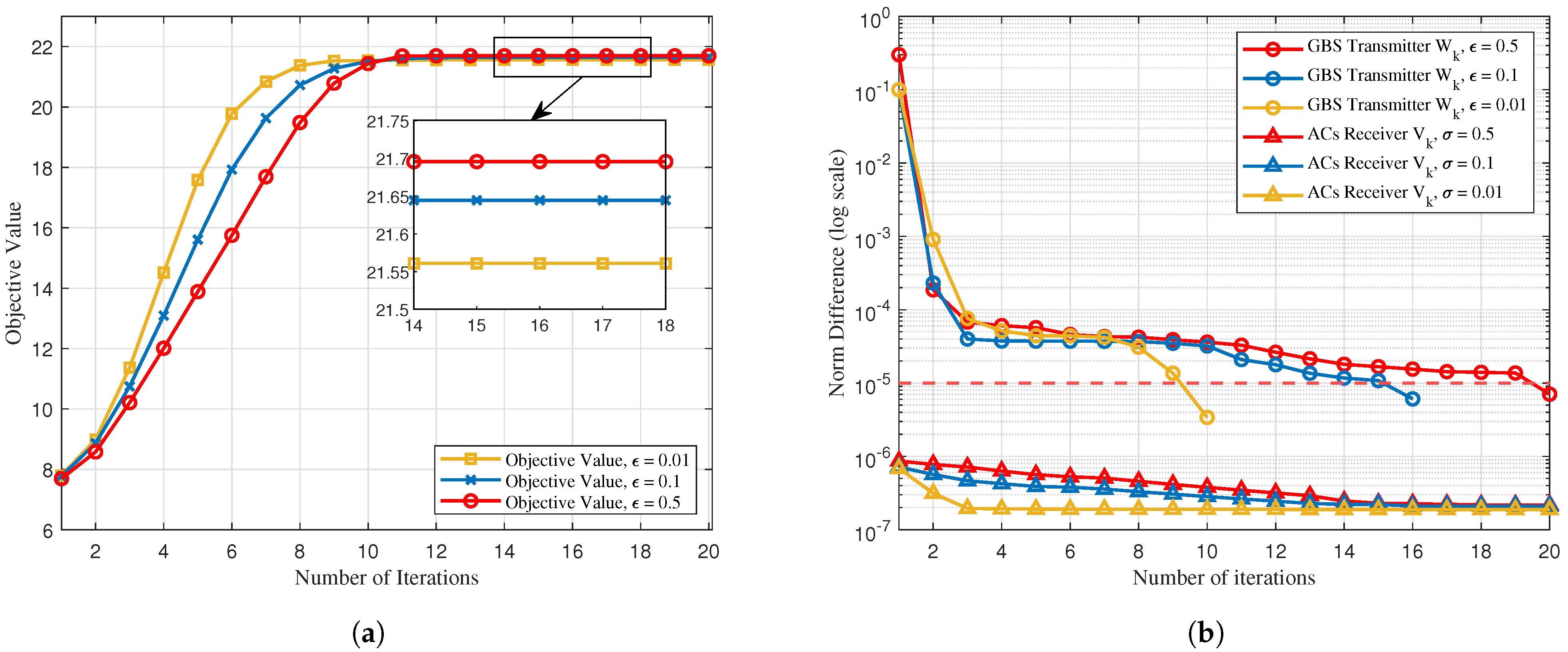
  • We develop an alternating optimization (AO) algorithm solved alternatively, where the original problem is decomposed into two subproblems. By combining the GBS transmit BF and the power allocation subproblems, we construct the auxiliary variables, which incorporate the optimization variables to simplify the optimization process. Afterwards, the penalty-based method is invoked to handle the non-convex constraint for the covariance matrix of BF. For the airborne receivers’ BF design, we effectively solve them by utilizing the sequential rank-one constraint relaxation (SROCR) while fixing the other optimization variables.
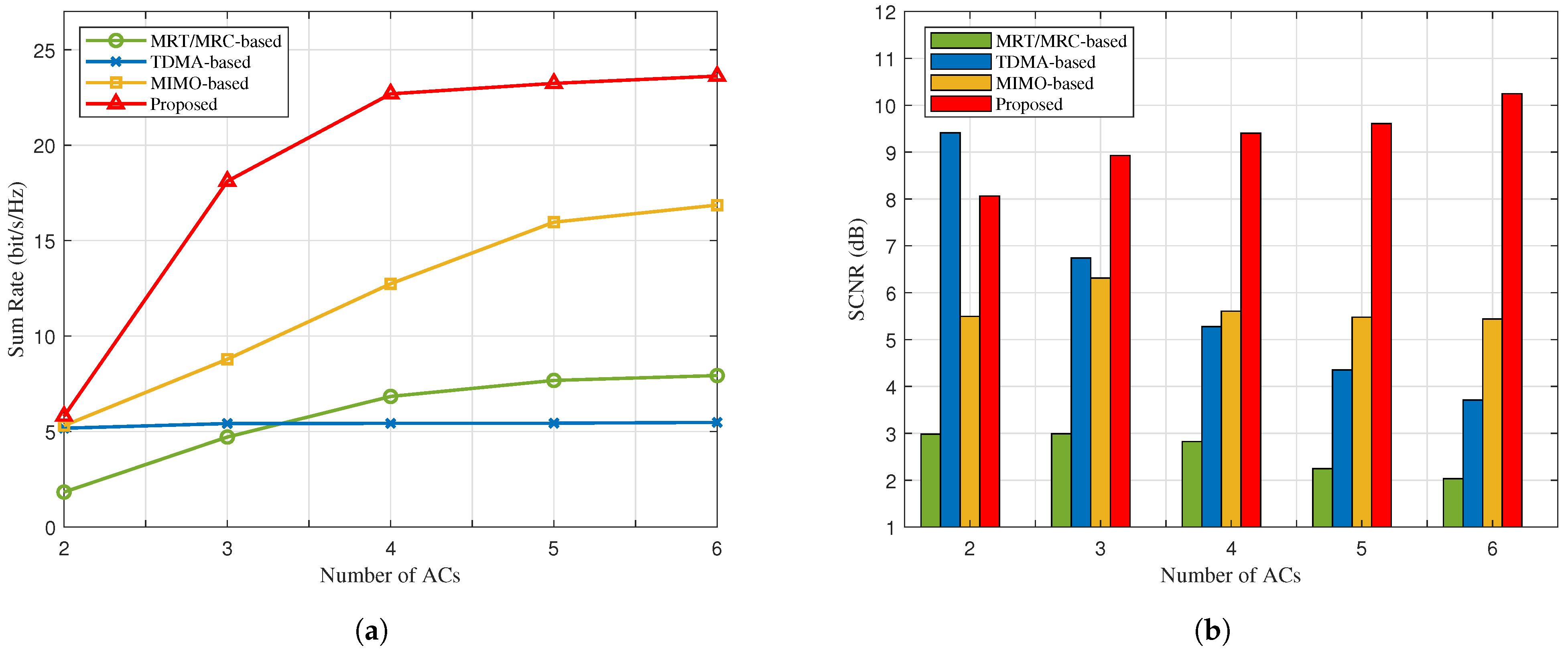
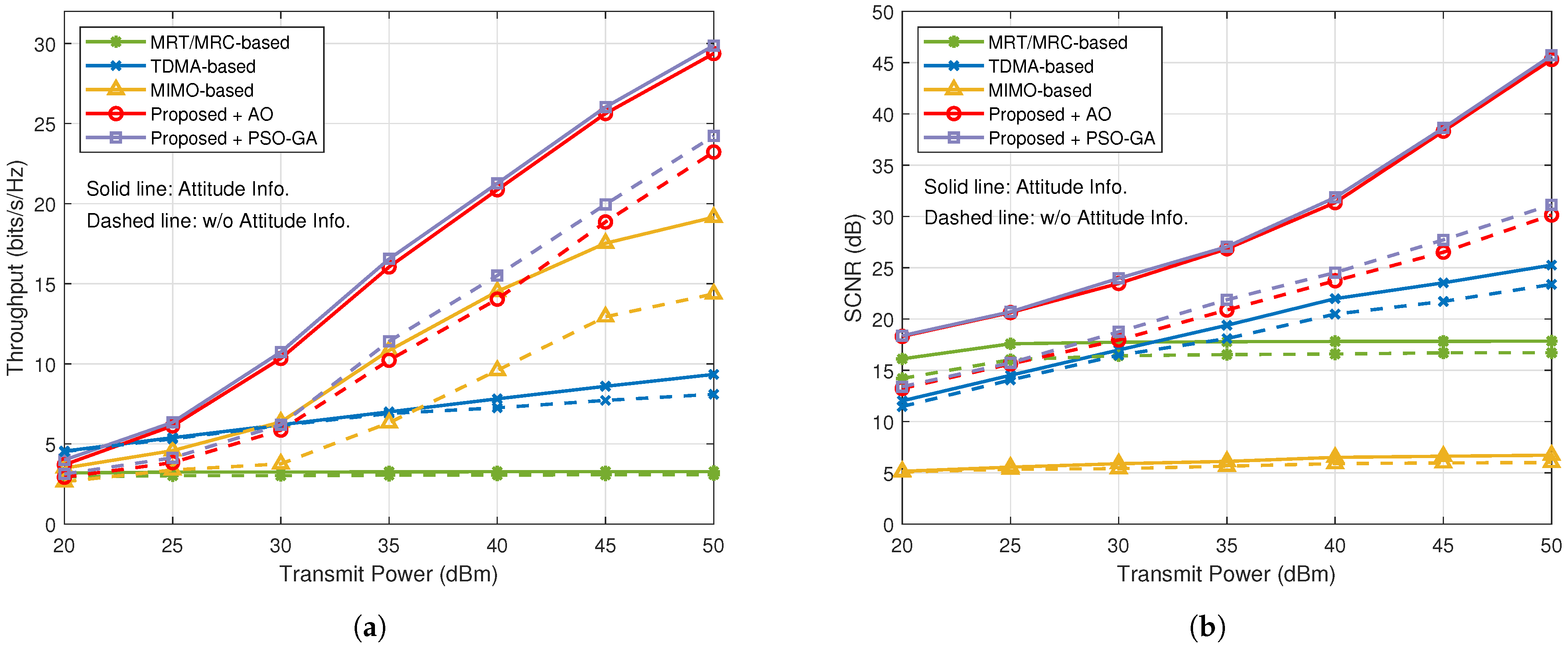
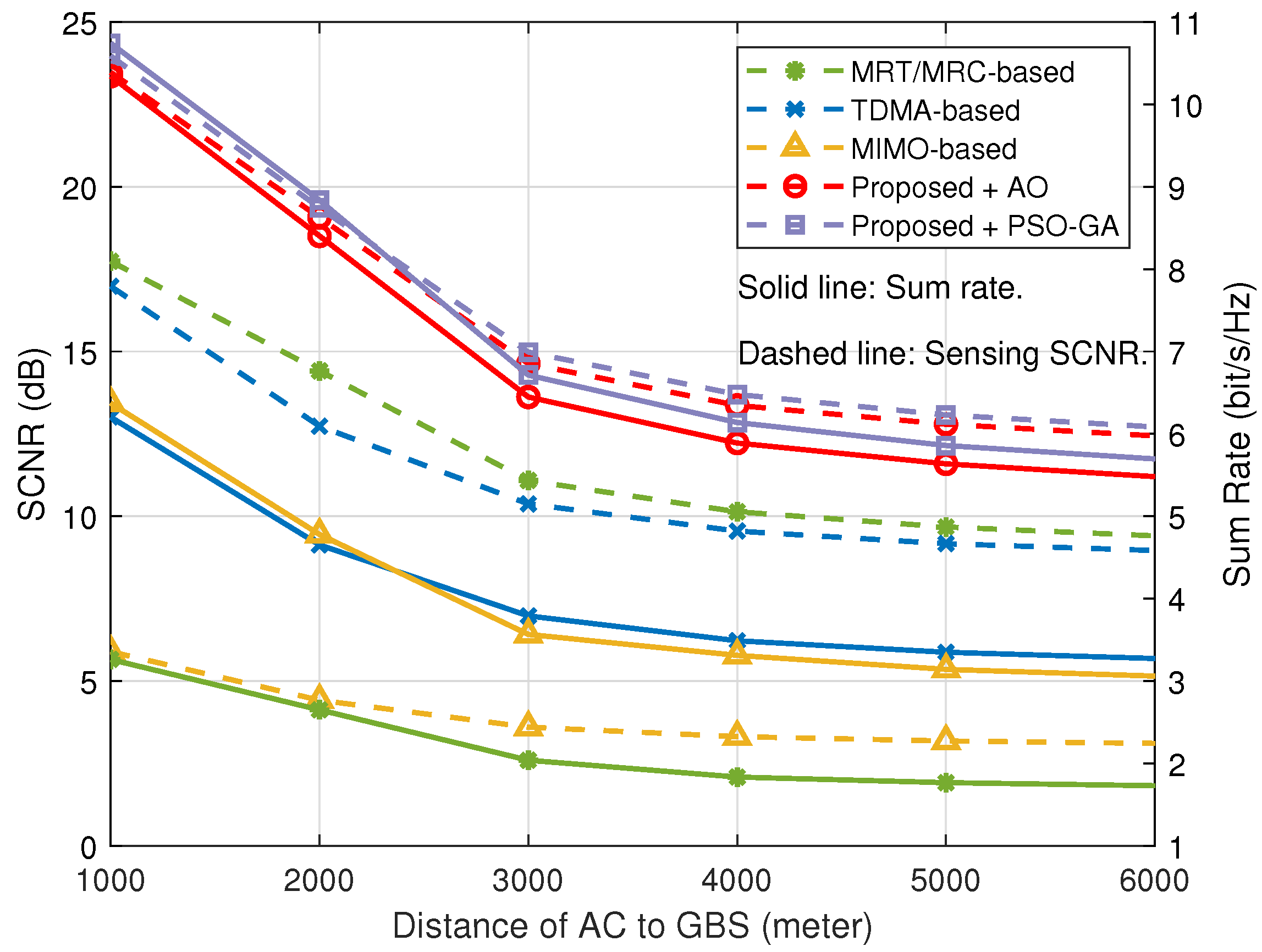
  • Numerical results indicate that the proposed algorithm outperforms benchmark schemes in terms of both the sum rate and the sensing performance for the dual-function of communication and radar. It is demonstrated that the proposed NOMA-motivated MIMO IACRS schemes significantly improve A2G datalink performance, enabling the ACS to receive messages while maintaining high-quality radar detection. Furthermore, the system performance gain becomes significant when the AC’s attitude is considered.

1.3. Organization and Notation

The rest of this paper is organized as follows. In Section 2, we introduce the IACRS model and formulate the joint sum rate and sensing SCNR problem. In Section 3, an AO-based iterative algorithm is developed to solve the formulated maximizing problem. Numerical results are presented in Section 4 to verify the effectiveness of the proposed algorithms compared to other benchmarks. Finally, conclusions are drawn in Section 6.
Notation: Matrices, vectors and scalars are denoted by bold-face upper-case, bold-face lower-case, and italic letters, respectively. C N × 1 denotes the space of N × 1 complex-valued vectors. For a vector a , a H denotes its (Hermitian) conjugate transpose, and a denotes its Euclidean norm.; X 0 indicates that matrix X is positive semidefinite; rank ( X ) and Tr ( X ) denote the rank and the trace of X , respectively. X * , X 2 are the nuclear norm and spectral norm of matrix X , respectively. CN ( μ , σ 2 ) denotes the distribution of a circularly symmetric complex Gaussian (CSCG) random variable with mean μ and variance σ 2 . The Kronecker product operator is denoted by ⊗.

2. System Model and Problem Formulation

In this section, we begin by introducing the NOMA-motivated MIMO IACRS model along with the corresponding channel model. Then, we present the coordinate transformation mechanism to illustrate the relationship between the AC’s attitude and the beam pointing. Lastly, we provide the problem formulation.

2.1. System Description

As illustrated in Figure 1, an A2G MIMO integrated communication and radar system is considered. It has a dual-functional GBS and K ACS indexed by k K = 1 , . . . , K . We assume that the communication system and the radar function are allocated on the same frequency band, which is similar to the case of the dedicated bands allocated to the L-DACS and DME system. The dual-functional GBS is installed with a UPA comprising M G = M G , x × M G , y transmit antennae. The k-th AC is also equipped with a UPA consisting of M A = M A , x × M A , y antennae. Given the A2G multipath components, the digital BFs are employed at both the GBS and ACS so that the transmission of the data stream for the k-th AC can be realized.
The dedicated radar sensing signal is assumed to be independent of the information symbols. Let s c , k and s r , k denote the transmitted communication signal and radar sensing signal intended for the k-th AC, respectively. Since the signals transmitted by the GBS in various time blocks have the same form, we focus on the t-th time block, which consists of T consecutive time slots, and the time-block index t is omitted in the following. The BF constructed for the k-th AC denoted by the transmit beamforming matrix w k C M G × 1 . Therefore, the transmitted dual-functional signal x C M G × 1 consists of the data signal and sensing signal for all ACSs:
x = k K w k ( α c , k s c , k + α r , k s r , k ) , k K ,
where α c , k 0 and α r , k 0 denote the power allocation factor of the communication and radar sensing signals of the k-th AC, respectively. Without loss of generality, we have α c , k + α r , k = 1 . Thus, the transmit power of the dual-functional GBS can be calculated as
E ( x x H ) = k K Tr ( w k w k H ) P G ,
where P G is the transmit power constraint for GBS. Different from existing research contributions that concern multiple communication users served by NOMA [8], NOMA-motivated technology is employed at the GBS to support both the communication and the sensing function for the same AC in this work. Considering the high-power signal characteristic of the DME system with information embedded, we set the fixed SIC order; it is known that SIC ordering has no influence on the high signal-to-noise ratio (SNR) slope of the ergodic communication rate and the sensing rate [32]. Specifically, the AC first deals with the radar signal by treating the communication signal as interference. The estimated radar signal is then subtracted from the received signal, with the remaining portion utilized for demodulating and decoding the communication signal. In the following, the radar sensing model and communication model of the proposed system will be introduced.
(1) MIMO Radar Sensing Model: Unlike primary radar systems that measure the orientation and distance of targets using the detected reflections of radio signals [33], the DME system relies on targets equipped with a radar transponder. It responds to each interrogation signal by transmitting encoded data containing the requested information. Hence, the transmit beam pattern used for typical radar detection is not a feasible metric considering the operating mode of DME. For the radar sensing function with the interrogation mode, we define the SCNR as the key metric. The SCNR represents the radar system’s detection range and sensitivity, which directly influence the probability of detection. It is determined by the gain of the line-of-sight (LoS) path and the situation of the clutter. The AC-received superimposed radar sensing signal is given by
y r , k = v k H β 0 a A θ A , LoS , ϕ A , LoS a G H θ G , LoS , ϕ G , LoS x AC target + v k H c clutter + v k H z r , k noise ,
where v k C M A × 1 represents the receive beamforming matrix of the k-th AC adhering to the power constraint Tr ( v k v k H ) P A , k , k K , β 0 denotes the complex-valued gain of the LoS path, and  z r , k C M A × 1 stands for the additive white Gaussian noise (AWGN), satisfying CN ( 0 , I r , k ) . The clutter, represented by c C M A × 1 , follows c CN ( 0 , R c ) including the non-line-of-sight (NLoS). It can generally be modeled as either signal-independent or signal-dependent. In the case of signal-independent clutter, the covariance matrix R c is assumed to remain constant. Conversely, for the signal-dependent clutter, it can be can be modeled as
c = l = 1 L β l a A θ A , l , ϕ A , l a G H θ G , l , ϕ G , l x = l = 1 L β l A GA , l x ,
where L is the number of NLoS rays, and β l represents the complex-valued gain of the NLoS path. The steering vectors at the GBS and AC are represented by a G θ G , · , ϕ G , · C M G × 1 and a A θ A , · , ϕ A , · C M A × 1 , respectively. Detailed expressions are provided in Section 2.3. The variables θ G , · and ϕ G , · ( θ A , · and ϕ A , · ) denote the azimuth and elevation components of the AoD at GBS (AoA at AC) for the LoS and NLoS paths, respectively. Given x in (1), the corresponding covariance matrix for the clutter can be calculated as
R c = k = 1 K l = 1 L ( β l A GA , l w k ) ( β l A GA , l w k ) H = k = 1 K l = 1 L β l 2 A GA , l w k w k H A GA , l H .
By employing classical iterative methods [34], R c can be considered constant when the BF matrix remained fixed following the previous iteration. Consequently, in the subsequent discussion, we will assume that the clutter covariance matrix remains constant during the single iteration. From (3), we set A GA , 0 = a A θ A , LoS , ϕ A , LoS a G H θ G , LoS , ϕ G , LoS as the LoS component. The sensing SCNR for the radar signal at the k-th AC is given as
T r , k = α r , k v k H β 0 A GA , 0 w k 2 α c , k v k H β 0 A GA , 0 w k 2 + v k H ( c + z r , k ) 2 .
(2) MIMO Communication Model: Given the transmit signal x in (1), the received communication signal of the k-th AC is expressed as
y c , k = v k H h GA , k w k α c , k s c , k desired communication signal + v k H h GA , k w k α r , k s r , k inter - function sensing interference removed by SIC + v k H h GA , k i k K w k ( α c , i s c , i + α r , i s r , i ) inter - aircraft interference not eliminate + v k H n c , k ,
where h GA , k C K A × K G denotes the spatial–frequency domain GBS-AC channel matrix of the k-th AC. The channel noise n c , k follows n c , k CN ( 0 , σ c 2 I c , k ) , where σ c 2 represents the average noise power. As our proposed IACRS framework is designed to address co-frequency interference for LDACS, the statistical value of σ c 2 can be obtained from the physical layer parameters provided in [2]. Inspired by NOMA technology, the inter-function interference will be eliminated by exploiting SIC while treating the signal from other ACSs as interference. As a result, the achievable rate of communication at the k-th AC after SIC is given is as follows:
R c , k = log 2 ( 1 + α c , k v k H h GA , k w k 2 i k K v k H h GA , k w i 2 + σ c 2 v k 2 ) .
Therefore, the communication throughput for all of the ACSs is represented by the achievable sum rate. In this study, perfect channel state information (CSI) estimation at the GBS is assumed to evaluate the maximum performance gain of the proposed IACRS framework. In practical scenarios, channel estimation techniques, such as those presented in [6,35], can be deployed into our framework to achieve accurate CSI acquisition with reasonable acceptable complexity and overhead. The Doppler shift is a significant factor in aeronautical scenarios, while developing a robust design that accounts for imperfect CSI is beyond the scope of the current work and will be addressed in future research.

2.2. Channel Model

As there are very limited dominant scatterers near both the GBS and the AC in the high-altitude A2G propagation surroundings, we adopt a geometric channel model with one LoS path and L NLoS paths. Assuming that the CSI remains unchanged within each time block (the duration of each time block depends on the coherence time of the A2G channel), h GA , k in the t-th time block can be expressed as a Rician model:
h GA , k = κ 1 + κ h GA , k LoS + 1 1 + κ h GA , k NLoS , k K ,
where κ denotes the Rician factor, which quantifies the energy ratio between the LoS and NLoS paths. h GA , k LoS is the LoS component of the k-th AC, and it can be expressed as
h GA , k LoS = β 0 a A θ A , LoS , ϕ A , LoS a G H θ G , LoS , ϕ G , LoS .
Similar to the channel state of the LoS path h GA , k LoS , h GA , k NLoS is the set as the NLoS component:
h GA , k NLoS = 1 L l = 1 L β l a A θ A , l , ϕ A , l a G H θ G , l , ϕ G , l .
β l is expressed by β l = h l e j 2 π T l T s , where T s is sampling period, and h l and τ l denote the large-scale fading gain and the delay of the l-th multipath component in the t-th time block, respectively. β 0 can be obtain by substituting h l and τ l with h LoS and T LoS , respectively.

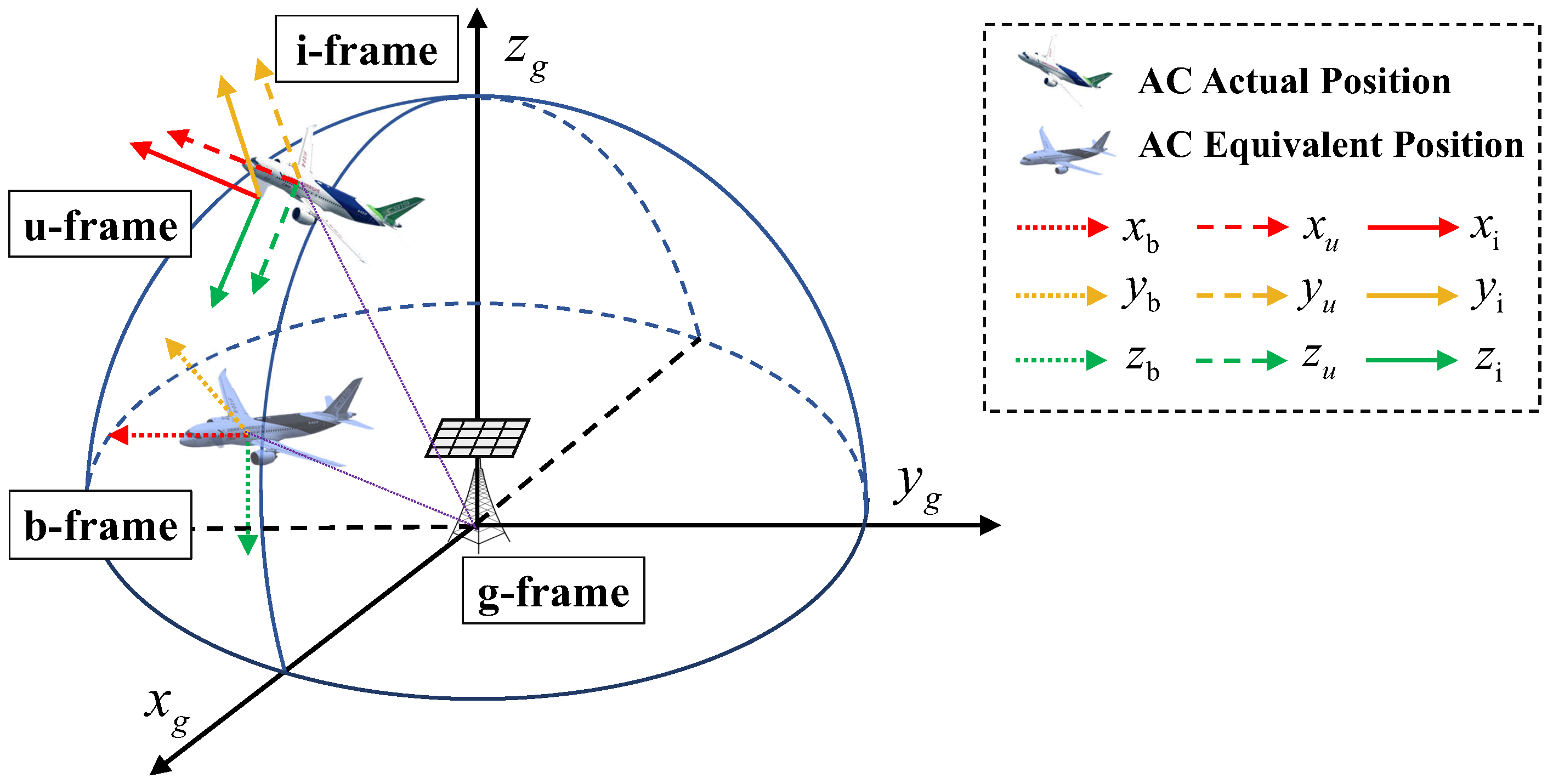
2.3. Coordinate Transformation

The steering directions at the GBS hinge on the AC’s position, while those at the AC side are also influenced by its attitude. To simplify the mathematical notations, we focus on deriving the AoD (denoted by θ G , LoS and ϕ G , LoS ) and the AoA (denoted by θ A , LoS and ϕ A , LoS ) of the LoS path, while the AoDs and AoAs of the NLoS paths can be calculated in the similar manner. To appropriately describe the relationship between the AoA (AoD) and the AC’s navigation information, we introduce the following reference frames, which are all illustrated in Figure 2.
  • The GBS geodetic coordinate frame (g-frame): Its origin is chosen as the center of gravity of the GBS-UPA, and its axes x g and y g are aligned with the directions of east and north, respectively. The axis z g is perpendicular to the ground surface pointing upwards, thus completing a right-handed coordinate frame. We assume that the row and column of the GBS-UPA are aligned with the axes x g and y g , respectively.
  • The AC body coordinate frame (b-frame): Its origin is the AC center of gravity (ACCG). The axes x b , y b , and z b are aligned with its longitudinal (forward), lateral (right), and vertical (downward) direction, respectively, which are parallel to x g , y g , and z g , respectively.
  • The inertial reference frame (i-frame): Its origin coincides with the ACCG, and its axes x i (roll axis) and y i (pitch axis)align along the directions of the AC’s head and starboard wing, respectively. And its axis z i (yaw axis) points downward, completing a right-handed coordinate frame.
  • The AC-UPA coordinate frame (u-frame): Its origin is chosen as the AC-UPA center of gravity. The axes x u and y u are aligned with the row and column of the AC-UPA, respectively. The axis z u is perpendicular to the plane spanned by the axes x u and y u . We assume that the axes x u , y u , and z u are parallel to x i , y i , and z i , respectively. On the basis of the relationship of the u-frame and the i-frame, the u-frame would be consistent with the i-frame when the attitude of the AC changes.
In the g-frame, the GBS’s position is fixed at the coordinate origin, while the AC’s position in the t-th time slot is denoted by p g = x g , y g , z g . On the other hand, the AC’s attitude in the t-th time slot is described by its Euler angles E = ψ , θ , ϕ in the i-frame. The angles ψ , θ , and ϕ are referred to as the roll, pitch, and yaw angles, respectively. Hence, the i-frame is consistent with the b-frame when the AC’s attitude is E = ( 0 , 0 , 0 ) . Note that the Euler angles are given with a specific rotation order: first around the roll axis, then the pitch axis, and finally, the yaw axis. The coordinate transformation matrix C b i expresses the relationship between the b-frame and the i-frame, which can be realized by three successive spatial rotations:
T 1 ( ψ ) = cos ψ sin ψ 0 sin ψ cos ψ 0 0 0 1 , T 2 ( θ ) = cos θ 0 sin θ 0 1 0 sin θ 0 cos θ , T 3 ( ϕ ) = 1 0 0 0 cos ϕ sin ϕ 0 sin ϕ cos ϕ .
The order of the rotations is critical to the orientation of the b-frame [27]. Thus, C b i can be mathematically expressed as
C b i = T 3 ( ϕ ) T 2 ( θ ) T 1 ( ψ ) = cos θ cos ψ cos θ sin ψ sin θ sin ϕ sin θ cos ψ cos ϕ sin ψ sin ϕ sin θ sin ψ + cos ϕ cos ψ sin ϕ cos θ cos ϕ sin θ cos ψ + sin ϕ sin ψ cos ϕ sin θ sin ψ sin ϕ cos ψ cos ϕ cos θ .
Since the GBS and AC positions, as well as the AC attitude, are defined in different coordinate frames, we introduce the concept of AC’s EP in the g-frame to make it tractable for the derivation of the steering vectors. The definition of EP is detailed in Appendix A. Given the p ˜ g and the corresponding AoA, the steering vector of the LoS path at the AC is expressed as
a A θ A , LoS , ϕ A , LoS = a A , x ( μ A , LoS ) a A , y ( ν A , LoS ) ,
where μ A , LoS = 2 π d λ c cos ( θ A , LoS ) sin ( ϕ A , LoS ) and ν A , LoS = 2 π d λ c sin ( θ A , LoS ) sin ( ϕ A , LoS ) represent the spatial frequencies along the axes x u and y u , respectively, with the antenna spacing of d and the carrier wavelength of λ c . The steering vectors a A , x ( μ A , LoS ) and a A , y ( ν A , LoS ) , along the axes x u and y u , respectively, are given by
a A , x ( μ A , LoS ) = 1 , e j μ A , LoS , . . . , e j ( M A 1 ) μ A , LoS ,
a A , y ( ν A , LoS ) = 1 , e j ν A , LoS , . . . , e j ( N A 1 ) ν A , LoS .
Similarly, the steering vectors of the NLoS paths at the AC are given by a A θ A , l , ϕ A , l = a A , x ( μ A , l ) a A , y ( ν A , l ) , where the AoAs are, respectively, replaced by the AoAs of the NLoS paths for the calculations of μ A , l and ν A , l . Furthermore, the steering vectors of the LoS and NLoS paths at the GBS are given by
a G θ G , LoS , ϕ G , LoS = a G , x ( μ G , LoS ) a G , y ( ν G , LoS ) ,
a G θ G , l , ϕ G , l = a G , x ( μ G , l ) a G , y ( ν G , l ) ,
where a G , x ( μ G , LoS ) and a G , x ( μ G , l ) , as well as a G , y ( μ G , LoS ) and a G , y ( μ G , l ) , are the steering vectors along the axes x g and y g , respectively.

2.4. Problem Formulation

As discussed in the previous subsection, two conflicting objectives must be addressed in the NOMA-motivated MIMO dual-function IACRS model: maximizing communication throughput and enhancing radar detection capability. To achieve a balance between communication and radar performance, an integrated waveform design is essential. This design should allocate spatial and power resources across the different propagation paths, ensuring that both the communication and radar functions meet their respective performance requirements. Specifically, the goal is to maximize the weighted sum of the achievable sum rate and the sensing SCNR for the system, subject to constraints that include the minimum communication rate for each AC, radar-specific requirements, and the total transmit power budget. The resultant optimization problem is formulated as
max { w k , v k , α c , k , α r , k } f ( R c , k , T r , k ) = ρ c k = 1 K R c , k + ρ r k = 1 K T r , k ,
s . t . R c , k R ¯ k , k K ,
T r , k T ¯ k , k K ,
k K Tr ( w k w k H ) P G , k K ,
Tr ( v k v k H ) = P A , k , k K
α c , k + α r , k = 1 , k K ,
α c , k 0 , α r , k 0 , k K ,
where ρ c 0 and ρ r 0 represent the regularization parameters, and R ¯ k denotes the minimum required communication data rate for the k-th AC. The constraint (17c) defines the minimum required sensing SCNR, with  T ¯ k representing the threshold value for the k-th AC. Additionally, (17d) and (17e) impose the maximum power constraints on the dual-functional GBS and each AC, respectively. The power allocation constraints, given by (17f) and (17g), are essential to ensure the implementation of SIC. The Problem (17) is non-convex, arising from the non-convex objective function and the non-convex constraints in (17b) and (17c). These constraints, highly coupled with the transmit BFs of the GBS { w k } , power allocation factors { α c , k , α r , k } , and the receiver BFs of the ACS, { v k } , present significant challenges. Consequently, finding the globally optimal solution is non-trivial. In the following, we propose an AO-based algorithm to find a high-quality near optimal solution.

3. AO-Based Alternative Optimization Algorithm

To tackle the above problems, we propose an AO-based algorithm, which decomposes the original optimization problem into two subproblems: the transmit BFs of the GBS, combined with power allocation; and the receiver BFs of the ACS. Each group of variables is iteratively optimized while keeping the others fixed, resulting in an iterative optimization process. The main challenge to solving Problem (17) arises from the fact that both the objective function and the left-hand-side (LHS) are non-concave with respect to the optimization variables. To address the issue, the penalty-based approach and the SROCR method are applied for addressing each subproblem iteratively.

3.1. GBS’ Transmit BFs Design and Power Allocation

We first solve the optimization problem with joint optimization of w k , α c , k , and α r , k for the given v k . The auxiliary variables are defined for the covariance matrix of the transmit beamforming matrix W k w k w k H , k K , where W k 0 , rank ( W k ) = 1 , and that of the receiver beamforming matrix V k v k v k H , k K , where V k 0 , rank ( V k ) = 1 . Further, we have equivalent channel h ˜ GA , k = v k H h GA , k . Then, Problem (17) can be reformulated as
max { W k , α c , k , α r , k } f ( R c , k , T r , k )
s . t . α c , k Tr ( H ˜ GA , k W k ) Γ c , k N k 0 , k K ,
α r , k T ¯ k v k H R ˜ c v k Tr ( W k Λ v , k ) T ¯ k α c , k 0 , k K ,
rank ( W k ) = 1 , W k 0 , k K ,
and additional constraints (17d)∼(17g), where H ˜ GA , k h ˜ GA , k h ˜ GA , k H , Γ c , k = 2 R ¯ k 1 , N k = i k K v k H h GA , k w i 2 + σ c 2 v k 2 , R ˜ c = R c + I and Λ v , k = β 0 2 A GA , 0 H V k A GA , 0 . Now, the reformulated Problem (18) is still non-convex due to the objective function and the non-convex constraints (18c) and (18d). In the following, we first address the non-convex objective function and the constraint (18c). To facilitate this, three auxiliary variables are introduced such that
ϖ r , k 2 = v k H R ˜ c v k = Tr ( V k R ˜ c ) , k K ,
J c , k = α c , k Tr ( H ˜ GA , k W k ) i k K Tr ( H ˜ GA , k W i ) + σ c 2 Tr ( V k ) , k K ,
L r , k = α r , k Tr ( W k Λ v , k ) α c , k Tr ( W k Λ v , k ) + ϖ k 2 .
Subsequently, Problem (18) can be equivalently reformulated as
max { W k , α c , k , α r , k } ρ c k = 1 K log 2 ( 1 + J c , k ) + ρ r k = 1 K L r , k
s . t . α r , k T ¯ k ϖ k 2 Tr ( W k Λ v , k ) T ¯ k α c , k 0 , k K ,
ϖ r , k 2 v k H R ˜ c v k , k K ,
J c , k α c , k Tr ( H ˜ GA , k W k ) i k K Tr ( H ˜ GA , k W i ) + σ c 2 Tr ( V k ) , k K ,
L r , k α r , k Tr ( W k Λ v , k ) α c , k Tr ( W k Λ v , k ) + ϖ r , k 2 ,
The Problem (22) is still subject to (17d)∼(17g), (18b), (18d). This is because, at the optimal solution of (22), it can clearly be verified that constraints (22c)–(22e), are always satisfied with equality. To illustrate, consider that at the optimal solution of (22), the value of J c , k can be increased to ensure that constraint (22d) is met with strict equality if it was initially satisfied with a strict inequality. This also increases the value of the objective function. We can see the same result when L r , k increases for the constraint (22d). Furthermore, if the constraint (22c) is strictly satisfied, ϖ k can be decreased, guaranteeing strict equality, while simultaneously increasing the value of the objective function. Hence, Problem (22) is equivalent to Problem (18).
The objective function in (22) is concave with respect to J c , k , and the second term in the LHS of (22b) is jointly concave with respect to ϖ k 2 and Tr ( W k Λ v , k ) . Moreover, the constraints (22c)–(22e) are non-convex regarding their respective optimization variables. To handle these, we introduce another two auxiliary variables, F c , k and G r , k , as follows:
J c , k ( i k K Tr ( H ˜ GA , k W i ) + σ c 2 Tr ( V k ) ) F c , k 2 α c , k Tr ( H ˜ GA , k W k ) ,
L r , k ( α c , k Tr ( W k Λ v , k ) + ϖ k 2 ) G r , k 2 α r , k Tr ( W k Λ v , k ) .
Next, we deal with constraint (23), which can be equivalently transformed into the following two constraints:
i k K Tr ( H ˜ GA , k W i ) + σ c 2 Tr ( V k ) F c , k 2 J c , k ,
F c , k 2 α c , k Tr ( H ˜ GA , k W k ) .
It is evident that constraint (25a) is non-convex due to the non-concavity of right-hand-side (RHS), whereas constraint (25b) is convex. However, the RHS of (25a) is a convex function joint with respect to F c , k and J c , k . A lower bound of the RHS of (25a) at the n 1 -th iteration of SCA can be derived by applying the first-order Taylor expression for any given feasible points, { F c , k ( n 1 ) , J c , k ( n 1 ) } , shown as
F c , k 2 J c , k ( F c , k ( n 1 ) ) 2 J c , k ( n 1 ) + 2 F c , k ( n 1 ) J c , k ( n 1 ) ( F c , k F c , k ( n 1 ) ) ( F c , k ( n 1 ) ) 2 ( J c , k ( n 1 ) ) 2 ( J c , k J c , k ( n 1 ) ) = 2 F c , k ( n 1 ) J c , k ( n 1 ) F c , k ( F c , k ( n 1 ) ) 2 ( J c , k ( n 1 ) ) 2 J c , k Π ( F c , k , J c , k ) , k K .
In a similar way, constraint (24) can also be equivalently transformed as
α c , k Tr ( W k Λ v , k ) + ϖ k 2 G r , k 2 L r , k ,
G r , k 2 α r , k Tr ( W k Λ v , k ) .
Constraint (27b) is obviously convex. Based on the definition of R c in (5), constraint (27a) can be obtained as
α c , k Tr ( W k Λ v , k ) + Tr ( V k R c ) + Tr ( V k ) G r , k 2 L r , k .
Constraint (27a) is non-convex as its RHS is not concave, while the RHS is a convex function joint with respect to G r , k and L r , k . Then, the approximation for the RHS of (27a) can be bounded using the first-order Taylor expansion at feasible points { G r , k ( n 1 ) , L r , k ( n 1 ) } as
G r , k 2 L r , k 2 G r , k ( n 1 ) L r , k ( n 1 ) G r , k ( G r , k ( n 1 ) ) 2 ( L r , k ( n 1 ) ) 2 L r , k Π ( G r , k , L r , k ) , k K .
For the non-convex constraint (22c), a lower bound can be obtained by the first-order Taylor expression as
ϖ r , k 2 ( ϖ r , k ( n 1 ) ) 2 + 2 ϖ r , k ( n 1 ) ( ϖ r , k ϖ r , k ( n 1 ) ) Ω ( ϖ r , k ) ,
where ϖ r , k ( n 1 ) is the feasible point at the n 1 -th iteration. The LHS of (30) is a convex function with respect to ϖ r , k . Therefore, we have the following reformulated optimization problem:
max X f ( J c , k , L r , k )
s . t . Ω ( ϖ r , k ) v k H R ˜ c v k , k K ,
i k K Tr ( H ˜ GA , k W i ) + σ c 2 Tr ( V k ) Π ( F c , k , J c , k ) , k K ,
α c , k Tr ( W k Λ v , k ) + ϖ k 2 Π ( G r , k , L r , k ) , k K ,
where X { W k , α c , k , α r , k , ϖ r , k , J c , k , L r , k , F c , k , G r , k } and f ( J c , k , L r , k ) replace the original objective function. The reformulated Problem (31) still needs to satisfy constraints (17d)–(17g), (18b), (18d), (22b), (25b), (27b). The non-convexity of this optimization problem arises primarily from the rank-one constraint (18d). A widely adopted approach to tackling this problem involves obtaining the semidefinite relaxation (SDR) of the reformulated problem, which omits the rank-one constraints. By removing the rank-one constraints, SDR could could efficiently obtain a global optimum through convex solvers like CVX. If the obtained solution does not satisfy the rank-one condition, the rank-one solution can be reconstructed through the Gaussian randomization method. The main advantage of SDR is its relatively low computational complexity as the relaxed problem typically needs to be solved only once. However, the solution derived from the relaxed problem is not guaranteed to be the global optimum of the original Problem  (17). One drawback of SDR is that significant performance degradation may occur due to the reconstruction. The process of reconstructing a rank-one solution can lead to significant performance degradation. Moreover, there is no assurance that the reconstructed rank-one solution will always satisfy all of the constraints for the original problem, potentially resulting in an infeasible solution.
To avoid the drawback, we endeavor to transform the rank-one constraints into penalty terms incorporated within the objective function. This reformulated result can be effectively addressed using SCA considering both solution optimality and feasibility. Building on this concept, the non-convex rank-one constraint (18d) is equivalent to the equality constraint:
W k * W k 2 = 0 , k K ,
where · * and · 2 denote the nuclear norm and spectral norm of the matrix, respectively. It can be readily verified that if the covariance matrix is of rank-one, the above equality constraint (32) is certainly satisfied for any W k , satisfying constraint (18d). Otherwise, the inequality W k * W k 2 > 0 must be maintained if the matrices are not rank-one. Thus, the penalty term for the rank-one equality constraint is introduced to the objective function of Problem (17), yielding the following optimization problem:
max X f ( J c , k , L r , k ) 1 η k K ( W k * W k 2 ) , s . t . ( 17 d ) ( 17 g ) , ( 18 b ) , ( 18 d ) , ( 22 b ) , ( 25 b ) , ( 27 b ) .
where η is the regularization parameter, serving as a penalty factor. The violation of (32) is penalized by the factor 1 η when W k is not of rank-one. It is important to recognize that the selection of η has a significant impact on the objective function. As  η tends towards 0, causing 1 η to approach , the rank of matrix W k will definitely be one. Nevertheless, in this case, the objective function will be primarily dominated by the penalty term, leading to a bad solution in terms of maximizing both communication throughput and radar detection capability. To tackle this, we can initialize η with a sufficiently large value to obtain a good starting point for the optimization problem. Subsequently, η can be gradually reduced to a sufficiently small value with the update rule η = ε η , 0 < ε < 1 . As a result, feasible rank-one matrix solutions associated with a near-optimal performance can eventually be obtained. However, the spectral norm as the second term in the penalty introduces non-convexity to the objective function. To tackle this, we apply the first-order Taylor expansion around the feasible point W k ( n 1 ) . We could obtain its upper bound W k 2 W ^ k ( n 1 ) , given by
W ^ k ( n 1 ) W k ( n 1 ) 2 Tr [ u max , k ( n 1 ) ( u max , k ( n 1 ) ) H ( W k W k ( n 1 ) ) ] ,
where u max , k ( n 1 ) is the eigenvector corresponding to the largest eigenvalue of W k ( n 1 ) . Thus, Problem (33) can be approximated as
min X f ( J c , k , L r , k ) + 1 η k K W k * + W ^ k ( n 1 ) , s . t . ( 17 d ) ( 17 g ) , ( 18 b ) , ( 18 d ) , ( 22 b ) , ( 25 b ) , ( 27 b ) .
Problem (35) is a quadratic semidefinite program (QSDP) that can be efficiently addressed using CVX. The iterative procedure will terminate when the penalty term becomes sufficiently small within a predefined accuracy, thereby satisfying the condition k K ( W k * W k 2 ) ϵ 0 . Algorithm 1 provides a comprehensive outline of the penalty-based procedure developed to address Problem (18).
Algorithm 1 Penalty-based approach to solve the joint transmit BF design and power allocation subproblem (35).
1:
Initialize feasible points { W k 0 , α c , k 0 , α r , k 0 } and the penalty parameter η .
2:
repeat: outer loop
3:
      Set iteration index n = 0 for inner loop.
4:
      repeat: inner loop
5:
            Use (19)–(21), (23) and (24) to calculate the current value { ϖ r , k ( n 1 ) , J c , k ( n 1 ) , L r , k ( n 1 ) , F c , k ( n 1 ) , G r , k ( n 1 ) } .
6:
            Solve the convex problem (35) with given feasible points, and the obtained optimal variables are denoted by { W k * , α c , k * , α r , k * } .
7:
             { W k ( n 1 + 1 ) , α c , k ( n 1 + 1 ) , α r , k ( n 1 + 1 ) } by the obtained optimal solutions and n 1 = n 1 + 1 .
8:
      until the fractional for the objective function variation value lowers below a predefined threshold ϵ inner > 0
9:
      Update feasible points { W k 0 , α c , k 0 , α r , k 0 } by the current optimal solutions.
10:
  Update η = ε η .
11:
until the norm difference constraint is lower than the maximum tolerable threshold ϵ outer > 0 .

3.2. ACS Receiver BFs’ Design

To optimize v k for a given w k , α c , k , and α r , k , the auxiliary variable g ˜ GA , k = h GA , k w k is introduced, which is the equivalent channel when w k is fixed. In the following, we also deal with the non-convex objective function and tackle the rank-one constraint. First, we deal with the term for the communication throughput, which can be expressed as
R c , k = log 2 ( 1 + α c , k Tr ( V k G ˜ GA , k ) i k K Tr ( V k G ˜ GA , i ) + σ c 2 Tr ( V k ) ) = log 2 ( α c , k Tr ( V k G ˜ GA , k ) + i k K Tr ( V k G ˜ GA , i ) + σ c 2 Tr ( V k ) ) log 2 ( i k K Tr ( V k G ˜ GA , i ) + σ c 2 Tr ( V k ) ) J k ,
where G ˜ GA , k g ˜ GA , k g ˜ GA , k H . The non-convexity of the objective function originates from the second term J k . However, since the objective can be expressed as the difference of two concave functions, a concave lower bound can be established by applying the first-order Taylor expansion at specified feasible points ( V 1 ( n 2 ) , . . . , V K ( n 2 ) ) in the n 2 -th iteration of the algorithm as follows:
J k J ^ k log 2 ( i k K Tr ( V k ( n 2 ) G ˜ GA , i ) + σ c 2 Tr ( V k ( n 2 ) ) ) i k K Tr ( ( V k V k ( n 2 ) ) G ˜ GA , i ) + σ c 2 Tr ( V k V k ( n 2 ) ) ( i k K Tr ( V k ( n 2 ) G ˜ GA , i ) + σ c 2 Tr ( V k ( n 2 ) ) ) ln 2 .
Then, we define
R ^ c , k log 2 ( α c , k Tr ( V k G ˜ GA , k ) + i k K Tr ( V k G ˜ GA , i ) + σ c 2 Tr ( V k ) ) + J ^ k ,
which establishes a lower bound for R k c . By leveraging it, constraint (17b) can be transformed into a conservative approximation with R ^ k c R ¯ k . Next, we tackle the second term of the objective function. To achieve a smooth approximation, the SCNR is transformed into a decibel (dB) scale, thereby obtaining a lower bound for T k r :
T r , k T ^ r , k = log 10 ( α c , k Tr ( Λ w , k V k ) ) log 10 ( α c , k Tr ( Λ w , k V k n ) + Tr ( V k n R ˜ c ) ) α c , k Tr ( Λ w , k ( V k V k ( n 2 ) ) ) + Tr ( ( V k V k ( n 2 ) ) R ˜ c ) ( α c , k Λ w , k Tr ( V k ( n 2 ) ) + Tr ( V k ( n 2 ) R ˜ c ) ) ln 10 ,
where Λ w , k = β 0 2 A GA , 0 W k A GA , 0 H . We can observe that T ^ k r is a convex function with respect to V k such that the objective function with concavity is the addition of a concave function and an affine function. Hence, problem (17) can be rewritten as follows:
max V k f ( V k ) = ρ c k = 1 K R ^ c , k + ρ r k = 1 K T ^ r , k ,
s . t . R ^ c , k R ¯ k , k K ,
( α r , k T ¯ k α c , k ) β 0 2 Tr ( Λ w , k V k ) T ¯ k Tr ( V k R ˜ c ) 0 ,
rank ( V k ) = 1 , V k 0 , k K ,
and additional constraints (17d)–(17g). While the computing power of avionic computers is limited, it is difficult to employ the penalty-based approach to address the rank-one issue, so we invoke the SROCR method. The fundamental framework of the SROCR method is detailed in [36], demonstrating its capability to iteratively obtain a feasible rank-one solution with significantly lower complexity compared to the penalty-based approach. Rather than completely ignoring the rank-one constraint, the core concept of SROCR is to gradually relax this constraint, thereby making it easier to find a feasible solution. Moreover, the SROCR method can generate a locally optimal solution for a general rank-one constrained optimization problem, provided that the relaxed optimization problem (without the rank-one constraint) is convex. This ensures that the algorithm can effectively address the original problem while maintaining acceptable computational complexity. To facilitate this method, the non-convex rank-one constraint (40d) is replaced with the following relaxed convex constraint:
λ max ( V k ) δ ( n 2 ) Tr ( V k ) ,
where λ max ( V k ) is the largest eigenvalue of V k , and δ ( n 2 ) [ 0 , 1 ] denotes a relaxation parameter which controls the largest eigenvalue-to-trace ratio of V k in the n 2 -th iteration of the SROCR algorithm as the solution V k * is guaranteed to satisfy the following condition:
δ ( n 2 ) λ max ( V k * ) Tr ( V k * ) 1 .
Thus,  (41) will be equivalent to the SDR when δ ( n 2 ) = 0 , which omits the non-convex rank-one constraint. This motivates us to incrementally increase δ ( n 2 ) from 0 in iterations, allowing the transformed constraint to gradually converge to the actual rank-one constraint set as δ ( n 2 ) approaches 1. As a result, Problem (40) can be rewritten as the following relaxed optimization problem:
max V k f ( V k ) , s . t . ( u max , k ( n 2 ) ) H V k u max , k ( n 2 ) δ ( n 2 ) Tr ( V k ) , k K , ( 17 d ) ( 17 g ) , ( 40 b ) , ( 40 c ) ,
where u max , k ( n 2 ) is the eigenvector corresponding to the largest eigenvalue of V k ( n 2 ) , which is the obtained solution feasible with δ ( n 2 ) . Now, problem (43) has been reformulated into a convex problem, which can be solved using optimization tools such as CVX [37]. The optimal value obtained from (43) serves as a lower bound for the original problem. This is because the non-convex components have been replaced with their respective lower bound approximations, ensuring that the solution reflects a conservative result of the original problem. After each iteration, relaxation parameter δ ( n 2 ) is updated as
δ ( n 2 ) = min ( 1 , λ max ( V k ( n 2 ) ) Tr ( V k ( n 2 ) ) + σ ( n 2 ) ) ,
where σ ( n 2 ) is a predefined step size. If problem (43) is infeasible at the current step σ ( n 2 ) , we will reduce the step size as σ ( n 2 + 1 ) = σ ( n 2 ) / J , where J 2 , in order to speed up the process of making (43) solvable. Setting f ( V k ( n 2 ) ) as the objective function value achieved by solution V k ( n 2 ) , the algorithm will be terminated when f ( V k ( n 2 ) ) f ( V k ( n 2 1 ) ) ϵ 1 and 1 δ ( n 2 1 ) ϵ 2 are simultaneously satisfied, where ϵ 1 and ϵ 2 are convergence thresholds. Hence, the proposed method can be assured to converge to a locally optimal solution with rank-one constraint [38] by updating parameter δ ( n 2 ) and solving problem (43). The details of solving problem (40) with the SROCR method are summarized in Algorithm 2.
Theorem 1. 
Given a feasible initial point V k ( 0 ) , Algorithm 2 converges to a KKT stationary solution of problem (43), which is equivalent to problem (40).
The proof of Theorem 1 is detailed in Appendix A. According to the convexity of problem (43), its objective function’s value remains non-increasing in each iteration, which also demonstrates the convergence of (40).
Remark 1. 
The proposed SROCR algorithm facilitates an easier analysis of the rank-one optimization process. In principle, Algorithm 2 iteratively projects the largest eigenvector of the matrix variable V k onto an updated direction u max , k ( n 2 ) until all the power lies in a one-dimensional subspace. Furthermore, unlike penalty-based methods (like Algorithm 1), V k ( n 2 ) converges to a rank-one solution by monotonically increasing δ ( n 2 ) in a controlled and iterative manner. This ensures a progression toward the desired rank-one constraint without the need for non-convex penalty parameters.
Algorithm 2 SROCR method for solving the receiver BF design subproblem (43).
1:
Initialize convergence thresholds ϵ 1 and ϵ 2 , step size σ ( n 2 ) , relaxation parameter δ ( n 2 ) , and  n 2 = 0 .
2:
repeat
3:
      For given { δ ( n 2 ) , V k ( n 2 ) } , solve the problem (43).
4:
      if problem (43) is feasible then
5:
             V k ( n 2 + 1 ) = V k , σ ( n 2 + 1 ) = σ ( 0 ) .
6:
      else
7:
             V k ( n 2 + 1 ) = V k ( n 2 ) , σ ( n 2 + 1 ) = σ ( n 2 ) / J .
8:
      end if
9:
       n 2 = n 2 + 1 ,
10:
     update δ ( n 2 ) = min ( 1 , λ max ( V k ( n 2 ) ) Tr ( V k ( n 2 ) ) + σ ( n 2 ) ) .
11:
until  f ( V k ( n 2 ) ) f ( V k ( n 2 1 ) ) ϵ 1 and 1 δ ( n 2 1 ) ϵ 2 . V k * = V k ( n 2 ) .

3.3. Complexity Analysis

Following the above discussions, the proposed AO-based alternative algorithm is utilized to address the original problem (17), which starts by initializing a feasible solution, including the aforementioned two subproblems. The main computational burden of the proposed AO-based algorithm is primarily determined by the complexities of Algorithms 1 and 2. Given the solution accurancy E , the complexity Algorithm 1 is O ( I o I i ( K M G 3.5 + ( 7 K ) 3.5 ) log ( 1 / E ) ) , where I i , I o and 7 K denote the number of inner and outer iterations required for convergence and the number of scalar optimization variables, respectively. Considering that the relaxed problem (43) is a standard SDP, Algorithm 2 exhibits a complexity of O ( ( K M A 3.5 ) log ( 1 / E ) ) . Thus, the total computational complexity of the AO-based algorithm is given by O ( ( I o I i ( K M G 3.5 + ( 7 K ) 3.5 ) + K M A 3.5 ) log ( 1 / E ) ) .

4. Results

To evaluate the performance of the proposed IACRS, we present numerical results obtained from Monte Carlo simulations in this section. The number of aircraft K is two in the default scenario. In particular, we assume that the GBS and ACS are all equipped with UPA with the same number of elements M G = M A = 4 × 4 , which involves half-wavelength spacing between adjacent antennae. The channels between the GBS and the ACS are assumed to experience Rician fading with the path loss of L k = L 0 + 20 log 10 ( d k ) ( dB ) , where L 0 is the path loss at the reference distance d = 1 meter (m), and d k represents the distance from the GBS [23]. The initial penalty factor of Algorithm 1 is set to η = 10 5 , and the convergence thresholds of inner and outer loops are set to ϵ inner = 1.001 and ϵ outer = 10 5 . The initial step size of Algorithm 2 is set to σ ( 0 ) = 0.1 , and the convergence thresholds for the difference in the objective function and the relaxation parameter are set to ϵ 1 = 10 3 and ϵ 2 = 10 5 , respectively. All numerical results are obtained using 300 Monte-Carlo simulations with random channel realizations. By normalizing the noise power, the derivations can be simplified. Without loss of generality, we set the noise power σ c 2 = 1 . Table 2 summarizes the default parameters of the simulation system. Unless otherwise specified, these default parameters are used.
For performance comparison, we consider the following benchmark schemes.
  • TDMA-based dual-function scheme: In this scheme, the GBS with multi-antenna successively transmits dedicated messages and interrogation-detecting signal to the ACS over 2 K time slots, employing one common BF. Accordingly, for the TDMA-based scheme, the sensing SCNR at the k-th AC is given by
    T k TDMA = 1 2 K v k H β 0 A GA , 0 w k 2 v k H ( c + z r , k ) 2 ,
    and the corresponding achievable rate for the k-th AC is
    R k TDMA = 1 2 K log 2 ( 1 + v k H h GA , k w k 2 σ c 2 v k 2 ) .
    The problem of maximizing the sum of T k TDMA and R k TDMA can be solved using the SCA algorithm as there are no inter-aircraft or inter-function interference terms involved.
  • MIMO-based dual-function scheme: In this scheme, the MIMO-only GBS transmits communication data to the ACS, employing distinct BFs, which are also simultaneously utilized for the detection of the ACS. Notably, each AC directly receives its intended signal while treating the signals for other ACS as interference without the assistance of SIC, which means a low level of integration. Therefore, the sensing SCNR and the sum rate for the transmitted signal at the AC are similar, with (3) and (7), respectively.
  • MRT/MRC-based dual-function scheme: In this scheme, the system model is the same as the proposed integrated framework, while using a linear transmitter and receiver, a maximum-ratio transmission/maximum-ratio combining (MRT/MRC) [40]. Hence, the approximate closed-form expressions of the transmit BFs of GBS and the receiver BFs of the ACS can be obtained.
In Figure 3a, the convergence behavior of the proposed algorithm is studied with varying values of the reduction factor ϵ . The numerical results indicate that the objective function rapidly converges to a stable value for any values of the reduction factor, while the rank-one term approaches nearly zero after a few iterations. This behavior confirms the convergence of the proposed algorithm. It demonstrates that the algorithm effectively identifies a feasible rank-one solution with high performance, which is applicable to both the GBS transmitter and the airborne receiver. Furthermore, the results reveal that as the parameter ϵ decreases, the algorithm achieves faster convergence speed but results in lower objective values, which corresponds to reduced system performance. This highlights a trade-off between convergence speed and system performance. In Figure 3b, we use the equivalent norm difference, W k * W k 2 , V k * V k 2 , k K , as an evaluation metric to assess the results of both the penalty-based approach and the SROCR method for the rank-one constraint. It can also be observed that the value of σ has little or no effect on the rank-one term, so we only focus on selecting ϵ in Figure 3a. Additionally, as ϵ decreases, the proposed algorithm exhibits faster convergence but leads to a lower objective value, i.e., worse system performance, reflecting a trade-off. Therefore, in the following simulations, we set ϵ = 0.1 , which provides a balance between convergence speed and system performance.
We evaluate the impact of the AC’s number on the proposed IACRS framework in Figure 4. Different scenarios for AC’s number are set as K = { 2 , 3 , 4 , 5 } , with their azimuth positions given by the sets [ 0 , π 2 ] , [ 0 , π 2 , π ] , [ 0 , π 2 , π , 3 π 2 ] , [ 0 , π 2 , π , 3 π 2 ] , and [ 0 , π 3 , 2 π 2 , π , 4 π 3 ] , respectively. It is shown that the objective value in the proposed scheme increases consistently during the iterations, regardless of the number of ACSs. On the one hand, the number of iterations increases as the number of ACSs grows. For instance, when K = 2 , the objective value gradually rises over approximately seven iterations to attain converge. However, when the number of ACSs is increased to K = 5 , the iterations rise to around 12. This increase in the number of iterations is attributed to the expanded search space resulting from the increased number of ACs, which requires more computational effort to achieve convergence. On the other hand, it can be observed that the growth rate of the objective value slows down as the number of ACSs increases. This is because the channel correlation among the ACSs becomes stronger with the larger number of ACSs, leading to increased inter-aircraft interference.
Further investigation of the achievable sum rate and average SCNR versus the number of ACSs is given in Figure 5. We consider different scenarios for AC’s number as K = { 2 , 3 , 4 , 5 , 6 } , with their azimuth positions given by the sets [ 0 , π 2 ] , [ 0 , π 2 , π ] , [ 0 , π 2 , π , 3 π 2 ] , [ 0 , π 2 , π , 3 π 2 ] , [ 0 , π 3 , 2 π 2 , π , 4 π 3 ] , and [ 0 , π 3 , 2 π 2 , π , 4 π 3 , 5 π 3 ] , respectively. All ACSs remain at an elevation angle of π 3 , which is consistent with a typical cruise situation. It can be observed that the sum rate of all schemes, except the TDMA-based scheme, initially increases and then converges as K increases. This trend can be explained as follows: for small values of K, increasing the number of ACSs provides more DoFs, which can be exploited to enhance the sum rate. However, as K becomes larger, the azimuth angles between the ACSs become smaller, leading to increased channel correlation. Strong channel correlation limits spatial DoFs, making it difficult for beamforming to effectively separate aircraft signals, which reduces system capacity and spectral efficiency. Regarding the average SCNR, the MIMO-based scheme exhibits an initial increase followed by a decrease as K increases. In contrast, the proposed scheme is the only one for which the average SCNR consistently increases with the number of ACSs. This result highlights the effectiveness of the proposed framework in maintaining robust radar sensing performance, even as the number of ACSs grows. The MRT/MRC scheme does not benefit from the NOMA-motivated framework, leading to a degradation in radar sensing performance. Additionally, the TDMA-based scheme shows a significantly lower average SCNR, primarily due to the reduction in available time slots allocated to the sensing function of each AC as the number of ACSs increases.
In Figure 6, it can be observed that the achievable sum rate of all schemes increases with the increasing transmit power P G in Figure 6a. Except for the transmit power, everything else remains unchanged from Table 2. Furthermore, the performance enhancement attained by the NOMA-motivated framework upon increasing P G is more significant than that of the TDMA-based scheme since NOMA benefits from a flexible resource allocation scheme, enabling double spectrum sharing. In Figure 6b, we also present the sensing SCNR obtained by the four schemes. It can be observed that the proposed scheme outperforms the other baseline schemes, especially at high transmit power. The SCNR gain achieved with effective attitude information, compared to position-only information, becomes more pronounced as transmit power increases. However, in contrast to the TDMA-based and proposed schemes, the sensing SCNR achieved by the MIMO-based scheme seems to be bounded by a certain value, with its enhancement becoming negligible. This is because in the absence of interference mitigation, the MIMO-based scheme becomes interference-limited. These results demonstrate that the proposed NOMA-motivated MIMO IACRS scheme is particularly suitable for aeronautical A2G communication in environments with saturated dedicated spectrum resources, while providing high-quality sensing SCNR for multiple-aircraft detection in secondary radar applications. It is worth noting that in terms of both the sum rate and the SCNR, the proposed AO algorithm performs nearly as well as the PSO-GA algorithm applied to the same scheme. As a heuristic algorithm, PSO-GA is capable of obtaining the global optimal solution to the problem. The simulation configuration parameters of PSO-GA are set as illustrated in Table 2 [22]. This indirectly proves the near-optimality of the feasible solutions obtained by the proposed algorithm.
In Figure 7, the simulation results highlight the trade-off between the sensing SCNR and the sum rate in the proposed system only under different NLoS conditions. As the number of NLoS paths increases, SCNR initially improves but eventually degrades due to the growing clutter from excessive multipath components. In contrast, the sum rate generally benefits from the presence of NLoS paths, reflecting the system’s ability to exploit spatial diversity. However, this improvement saturates as the system approaches its capacity to effectively handle multipath propagation. Additionally, it is clear that increasing the number of UPA elements results in a noticeable performance gain. In summary, there exists a trade-off between achieving higher data rates and maintaining sensing signal quality, as more NLoS components increase capacity but also introduce greater interference. To optimize system performance, careful management of multipath effects is essential to mitigate clutter while maximizing the benefits of spatial diversity.
To investigate the impact of communication distance, we conducted simulations by fixing the spatial distance between one AC and the GBS at 1000 m while varying the distance of the other AC. As shown in Figure 8, both the sum rate and SCNR decrease significantly as the distance increases, primarily due to the presence of the AC moving away from the GBS. Eventually, both metrics converge to a fixed value, which is determined by the aircraft maintaining a constant distance from the GBS. Furthermore, it can be observed that the performance degradation of the NOMA-motivated MIMO IACRS is less pronounced compared to other schemes. As a result, the proposed scheme maintains higher dual-functional performance, demonstrating its robustness in scenarios with varying communication ranges.

5. Discussion

The proposed IACRS framework leverages MIMO technology and an NOMA-inspired concept to enable efficient spectrum sharing between communication and radar functionalities. While these technologies offer significant theoretical advantages in improving spectral efficiency and system capacity, their practical deployment in real-world aviation environments still faces challenges. Addressing these challenges is important to achieving stable and reliable operation in complex scenarios. Below, we discuss these issues in detail and outline potential strategies to mitigate their impact.
First, we discuss complexity and optimality. The proposed AO algorithm provides an efficient approach to tackling non-convex optimization problems in the IACRS framework. While AO ensures near-optimal solutions, its inability to guarantee global optimality comes from the non-convexity of the problem space. To mitigate this limitation, we derived a convex lower-bound approximation for the original problem, enabling the algorithm to achieve a stable suboptimal solution with reduced computational overhead. Simulation results demonstrate that AO achieves an objective value within 2.19 % of the global optimal algorithm PSO-GA while reducing computation time in the small-scale simulation settings (e.g., 2 aircraft with 4 × 4 MIMO arrays). However, scalability remains a critical challenge; for scenarios involving more aircraft, the AO algorithm computation time grows exponentially, and convergence becomes unreliable. This limitation underscores the trade-off between optimality and scalability. Further exploration of distributed computing architectures could alleviate computational bottlenecks in large-scale deployments. Additionally, AI-driven techniques like reinforcement learning could dynamically adjust algorithm parameters based on real-time channel conditions, accelerating convergence.
Furthermore, the actual deployment of the IACRS framework also encounters challenges, especially in handling electromagnetic interference. Various radio devices with CNS functions are densely installed within the limited space of an AC. For instance, an Airbus 320 typically installs at least 30 antennae. This dense setup creates a complex airborne electromagnetic environment, leading to interferences such as adjacent-channel, co-channel, and out-of-band. The proposed IACRS framework mitigates inter-function interference and inter-aircraft interference through power-domain multiplexing and beamforming, respectively, while sudden disruptions, e.g., pulsed radar emissions or unauthorized jamming signals, remain a significant threat. Uncoordinated radar pulses in shared frequency bands can degrade NOMA’s power allocation efficiency, leading to packet loss. To address these issues, advanced anti-jamming technologies must be incorporated. Compressed sensing offers a promising solution by exploiting signal sparsity to reconstruct desired waveforms while suppressing interference. It can isolate communication signals from wide-band jamming by leveraging their temporal and spectral sparsity properties. Similarly, wavelet transform techniques enable multi-resolution analysis to detect and eliminate pulsed interference across diverse frequency bands. While our current study primarily focuses on the theoretical framework and algorithmic design, we recognize the importance of addressing hardware and implementation challenges to bridge the gap between theory and practice.
Admittedly, timely CSI updating is crucial. The beamforming performance and power allocation in the IACRS framework heavily are heavily reliant on accurate CSI. However, the highly dynamic aviation environment introduces rapid channel variations due to aircraft mobility, atmospheric turbulence, and multipath effects, making CSI acquisition inherently challenging. Current simulations assume perfect CSI, which overlooks practical limitations such as estimation errors, feedback delays, and quantization noise. At the cruising phase, the Doppler shift causes conventional pilot-based channel estimation methods to be ineffective. To bridge this gap, adaptive CSI estimation techniques must be developed. Compressed sensing-based channel tracking could reduce pilot overhead by exploiting channel sparsity in the angle-delay domain, while Kalman filter-based predictors could compensate for feedback delays by extrapolating future channel states. Furthermore, machine learning models could learn temporal correlations in channel variations such that trained BFs on historical flight data could predict the beamforming weights for upcoming maneuvers, reducing reliance on instantaneous feedback. However, these approaches demand rigorous validation under diverse flight scenarios, including extreme weather and congested airspace, to ensure robustness. Collaborative research with aviation stakeholders will be critical to collecting large-scale channel datasets and refining these algorithms for operational use.
Last but not least, the high-dynamic aviation environment imposes unique constraints on system design, particularly during high-speed velocity and in congested airspace. The Doppler effect caused by the high speed introduces frequency offsets that degrade OFDM subcarrier orthogonality and SIC accuracy, necessitating robust frequency synchronization algorithms. Based on real-time Doppler estimates, adaptive modulation and coding schemes could mitigate these effects by dynamically adjusting transmission parameters. Aircraft attitude changes further complicate MIMO channel modeling. While the proposed attitude-based dynamic framework captures gradual attitude variations, temporarily misaligned beamforming directions may occur. Integrating inertial measurement unit (IMU) data with beam tracking could address this by enabling real-time beam steering. A hybrid beamforming architecture could use IMU-derived attitude angles to pre-adjust analog BFs, while digital precoders fully utilize the spatial DoFs. Finally, multi-aircraft coordination protocols with interference management, inspired by vehicular ad-hoc networks (VANETs), could enhance situational awareness and spectrum utilization in congested airspace, ensuring stable and efficient operations under dynamic conditions. Recognizing these challenges does not emphasize a limitation of our current research but rather outlines a clear path for future work.

6. Conclusions

This paper proposes a novel NOMA-motivated MIMO dual-function scheme for IACRS, where an MIMO GBS transmits NOMA-structured superimposed radar sensing signals and communication messages to the ACS, achieving double spectrum sharing. For the proposed framework, corresponding BF optimization and power allocation problems are formulated for enhancing both communication and radar performance, while fulfilling the transmitted data rate and the sensing SCNR requirements. An AO-based algorithm is developed to find a near-optimal solution to solve the resultant non-convex optimization problem. Specifically, a new A2G MIMO channel model that accounts for AC dynamics, including both position and attitude, is introduced to characterize the steering direction. Since the AoDs and AoAs depend on the time-varying position and attitude, the proposed channel model significantly improves system performance. The numerical results demonstrate that the proposed scheme achieves superior dual-function system performance compared to the benchmark schemes. And it obtained a performance close to the global optimal algorithm PSO-GA. In contrast, the MRT/MRC scheme does not benefit from the NOMA-inspired framework as it relies only on valid channel information, resulting in inferior communication performance.

Author Contributions

Conceptualization, L.Y. and J.Z.; methodology, L.Y. and Q.Z.; software, L.Y.; validation, L.Y. and Q.Z.; formal analysis, L.Y.; investigation, L.Y.; resources, J.Z. and K.C.; data curation, L.Y.; writing—original draft preparation, L.Y.; writing—review and editing, Q.Z. and J.Z.; visualization, L.Y.; supervision, J.Z. and Y.Z.; project administration, J.Z., Y.Z. and K.C.; funding acquisition, J.Z. and K.C. All authors have read and agreed to the published version of the manuscript.

Funding

This research is supported by the funds from the National Natural Science Foundation of China (Grant Nos. U2133210, U2233216), the Fundamental Research Funds for the Central Universities (Grant No. YWF-24-JT-102), and the Postdoctoral Fellowship Program of CPSF (Grant No. GZB20240934).

Data Availability Statement

The original contributions presented in the study are included in the article, further inquiries can be directed to the corresponding author.

Conflicts of Interest

The authors declare no conflicts of interest.

Appendix A

This appendix provides the formal definition and proposition regarding the concept of the Aircraft’s Equivalent Position (EP), which is critical to understanding the derivation of AoDs/AoAs under varying aircraft positions and attitudes.
Definition A1. 
p ˜ g is named as the AC’s EP with respect to its current position p g . The AC’s EP in the g-frame, p ˜ g = x ˜ g , y ˜ g , z ˜ g , corresponds to the position where the AC with attitude E = ψ , θ , ϕ and current position p g results in the same AoA as when the AC has attitude E ˜ = ( 0 , 0 , 0 ) and p ˜ g .
In simpler terms, while the AoA depends on the AC’s position and attitude, it can equivalently be described solely by its EP. Then, the AC’s EP p ˜ g = x ˜ g , y ˜ g , z ˜ g can be derived as p ˜ g = C b i p g , where p ˜ g and p g lie on the same sphere centered at the GBS. Additionally, it can be observed that det ( C b i ) = 1 . Thus, we can conclude that p g = p ˜ g .

Appendix B

This appendix provides the proof of Theorem 1. Given a feasible initial point V k ( 0 ) , Algorithm 2 iteratively solves the convex problem (43) by alternately optimizing V k and u max , k ( n 2 ) . At each iteration, the algorithm updates δ ( n 2 + 1 ) and adjusts the step size σ ( n 2 + 1 ) based on the solution of problem (43). If the problem is solvable, the optimal solution V k ( n 2 + 1 ) is obtained, and the step size is reset to σ ( 0 ) ; otherwise, the step size is halved to ensure progress toward feasibility. The termination criteria, f ( V k ( n 2 ) ) f ( V k ( n 2 1 ) ) ϵ 1 and 1 δ ( n 2 1 ) ϵ 2 , guarantee that the algorithm converges to a solution satisfying the prescribed precision. Since problem (43) is convex and the constraints are continuously refined, the algorithm converges to a KKT stationary, which is equivalent to the original rank-one constrained problem (40) due to the equivalence established through the relaxation and the rank-one constraint enforcement. Thus, Algorithm 2 ensures convergence to a near optimal solution of the rank-one constrained optimization problem.

References

  1. Zhang, J. Aeronautical Mobile Communication: The Evolution from Narrowband to Broadband. Engineering 2021, 7, 431–434. [Google Scholar] [CrossRef]
  2. Schnell, M.; Epple, U.; Shutin, D.; Schneckenburger, N. LDACS: Future aeronautical communications for air-traffic management. IEEE Commun. Mag. 2014, 52, 104–110. [Google Scholar] [CrossRef]
  3. Neji, N.; de Lacerda, R.; Azoulay, A.; Letertre, T.; Outtier, O. Survey on the Future Aeronautical Communication System and Its Development for Continental Communications. IEEE Trans. Veh. Technol. 2013, 62, 182–191. [Google Scholar]
  4. Xiao, Z.; Zhu, L.; Liu, Y.; Yi, P.; Zhang, R.; Xia, X.G.; Schober, R. A Survey on Millimeter-Wave Beamforming Enabled UAV Communications and Networking. IEEE Commun. Surv. Tutor. 2022, 24, 557–610. [Google Scholar]
  5. Zhu, L.; Zhang, J.; Xiao, Z.; Cao, X.; Wu, D.O.; Xia, X.G. 3-D Beamforming for Flexible Coverage in Millimeter-Wave UAV Communications. IEEE Wirel. Commun. Lett. 2019, 8, 837–840. [Google Scholar]
  6. Chen, Z.; Tang, J.; Zhang, X.Y.; So, D.K.C.; Jin, S.; Wong, K.K. Hybrid Evolutionary-Based Sparse Channel Estimation for IRS-Assisted mmWave MIMO Systems. IEEE Trans. Wirel. Commun. 2022, 21, 1586–1601. [Google Scholar]
  7. Luong, N.C.; Lu, X.; Hoang, D.T.; Niyato, D.; Kim, D.I. Radio Resource Management in Joint Radar and Communication: A Comprehensive Survey. IEEE Commun. Surv. Tutor. 2021, 23, 780–814. [Google Scholar]
  8. Liu, Y.; Qin, Z.; Elkashlan, M.; Ding, Z.; Nallanathan, A.; Hanzo, L. Nonorthogonal Multiple Access for 5G and Beyond. Proc. IEEE 2017, 105, 2347–2381. [Google Scholar]
  9. Zhu, L.; Zhang, J.; Xiao, Z.; Cao, X.; Wu, D.O.; Xia, X.G. Millimeter-Wave NOMA with User Grouping, Power Allocation and Hybrid Beamforming. IEEE Trans. Wirel. Commun. 2019, 18, 5065–5079. [Google Scholar]
  10. Zheng, L.; Lops, M.; Eldar, Y.C.; Wang, X. Radar and Communication Coexistence: An Overview: A Review of Recent Methods. IEEE Signal Process. Mag. 2019, 36, 85–99. [Google Scholar]
  11. Liu, F.; Cui, Y.; Masouros, C.; Xu, J.; Han, T.X.; Eldar, Y.C.; Buzzi, S. Integrated Sensing and Communications: Toward Dual-Functional Wireless Networks for 6G and Beyond. IEEE J. Sel. Areas Commun. 2022, 40, 1728–1767. [Google Scholar] [CrossRef]
  12. Zhang, A.; Rahman, M.L.; Huang, X.; Guo, Y.J.; Chen, S.; Heath, R.W. Perceptive Mobile Networks: Cellular Networks with Radio Vision via Joint Communication and Radar Sensing. IEEE Veh. Technol. Mag. 2021, 16, 20–30. [Google Scholar] [CrossRef]
  13. Sturm, C.; Zwick, T.; Wiesbeck, W. An OFDM System Concept for Joint Radar and Communications Operations. In Proceedings of the VTC Spring 2009—IEEE 69th Vehicular Technology Conference, Barcelona, Spain, 26–29 April 2009; IEEE: New York, NY, USA, 2009; pp. 1–5. [Google Scholar]
  14. Agrawal, N.; Darak, S.J.; Bader, F. Spectral Coexistence of LDACS and DME: Analysis via Hardware Software Co-Design in Presence of Real Channels and RF Impairments. IEEE Trans. Veh. Technol. 2020, 69, 9837–9848. [Google Scholar] [CrossRef]
  15. Sturm, C.; Wiesbeck, W. Waveform Design and Signal Processing Aspects for Fusion of Wireless Communications and Radar Sensing. Proc. IEEE 2011, 99, 1236–1259. [Google Scholar] [CrossRef]
  16. Liu, F.; Zhou, L.; Masouros, C.; Li, A.; Luo, W.; Petropulu, A. Toward Dual-functional Radar-Communication Systems: Optimal Waveform Design. IEEE Trans. Signal Process. 2018, 66, 4264–4279. [Google Scholar] [CrossRef]
  17. Mahal, J.A.; Khawar, A.; Abdelhadi, A.; Clancy, T.C. Spectral Coexistence of MIMO Radar and MIMO Cellular System. IEEE Trans. Aerosp. Electron. Syst. 2017, 53, 655–668. [Google Scholar] [CrossRef]
  18. Qian, J.; Lops, M.; Zheng, L.; Wang, X.; He, Z. Joint System Design for Coexistence of MIMO Radar and MIMO Communication. IEEE Trans. Signal Process. 2018, 66, 3504–3519. [Google Scholar] [CrossRef]
  19. Zhou, Q.; Gong, Y.; Nallanathan, A. Radar-Aided Beam Selection in MIMO Communication Systems: A Federated Transfer Learning Approach. IEEE Trans. Veh. Technol. 2024, 73, 12172–12177. [Google Scholar] [CrossRef]
  20. Zhang, H.; Liu, W.; Zhang, Q.; Zhang, L.; Liu, B.; Xu, H.X. Joint Power, Bandwidth, and Subchannel Allocation in a UAV-Assisted DFRC Network. IEEE Internet Things J. 2025. Early Access. [Google Scholar] [CrossRef]
  21. Zhang, H.; Liu, W.; Zhang, Q.; Liu, B. Joint Customer Assignment, Power Allocation, and Subchannel Allocation in a UAV-Based Joint Radar and Communication Network. IEEE Internet Things J. 2024, 11, 29643–29660. [Google Scholar] [CrossRef]
  22. Qiao, Y.; Niu, Y.; Han, Z.; Xiong, L.; Wang, N.; Quek, T.Q.S.; Ai, B. Resource Allocation for ISAC and HRLLC in UAV-Assisted HSR System with a Hybrid PSO-Genetic Algorithm. IEEE Internet Things J. 2025, 12, 6790–6804. [Google Scholar] [CrossRef]
  23. Liu, F.; Masouros, C.; Li, A.; Sun, H.; Hanzo, L. MU-MIMO Communications with MIMO Radar: From Co-Existence to Joint Transmission. IEEE Trans. Wirel. Commun. 2018, 17, 2755–2770. [Google Scholar] [CrossRef]
  24. Dong, F.; Wang, W.; Hu, Z.; Hui, T. Low-Complexity Beamformer Design for Joint Radar and Communications Systems. IEEE Commun. Lett. 2021, 25, 259–263. [Google Scholar] [CrossRef]
  25. Chen, L.; Liu, F.; Wang, W.; Masouros, C. Joint Radar-Communication Transmission: A Generalized Pareto Optimization Framework. IEEE Trans. Signal Process. 2021, 69, 2752–2765. [Google Scholar] [CrossRef]
  26. Tsinos, C.G.; Arora, A.; Chatzinotas, S.; Ottersten, B. Joint Transmit Waveform and Receive Filter Design for Dual-Function Radar-Communication Systems. IEEE J. Sel. Areas Commun. 2021, 15, 1378–1392. [Google Scholar]
  27. Zhao, J.; Gao, F.; Wu, Q.; Jin, S.; Wu, Y.; Jia, W. Beam Tracking for UAV Mounted SatCom on-the-Move with Massive Antenna Array. IEEE J. Sel. Areas Commun. 2018, 36, 363–375. [Google Scholar] [CrossRef]
  28. Zhu, J.; Li, W.; Wong, K.K.; Jin, T.; An, K. Waveform Design of DFRC System for Target Detection in Clutter Environment. IEEE Signal Process. Lett. 2023, 30, 1517–1521. [Google Scholar] [CrossRef]
  29. Chen, L.; Wang, Z.; Du, Y.; Chen, Y.; Yu, F.R. Generalized Transceiver Beamforming for DFRC with MIMO Radar and MU-MIMO Communication. IEEE J. Sel. Areas Commun. 2022, 40, 1795–1808. [Google Scholar]
  30. Wang, Z.; Liu, Y.; Mu, X.; Ding, Z.; Dobre, O.A. NOMA Empowered Integrated Sensing and Communication. IEEE Commun. Lett. 2022, 26, 677–681. [Google Scholar] [CrossRef]
  31. Mu, X.; Liu, Y.; Guo, L.; Lin, J.; Hanzo, L. NOMA-Aided Joint Radar and Multicast-Unicast Communication Systems. IEEE J. Sel. Areas Commun. 2022, 40, 1978–1992. [Google Scholar] [CrossRef]
  32. Ouyang, C.; Liu, Y.; Yang, H. Revealing the Impact of SIC in NOMA-ISAC. IEEE Wirel. Commun. Lett. 2023, 12, 1707–1711. [Google Scholar] [CrossRef]
  33. Liu, F.; Masouros, C.; Petropulu, A.P.; Griffiths, H.; Hanzo, L. Joint Radar and Communication Design: Applications, State-of-the-Art, and the Road Ahead. IEEE Trans. Commun. 2020, 68, 3834–3862. [Google Scholar]
  34. Chen, C.Y.; Vaidyanathan, P.P. MIMO Radar Waveform Optimization with Prior Information of the Extended Target and Clutter. IEEE Trans. Signal Process. 2009, 57, 3533–3544. [Google Scholar]
  35. Ogbe, D.; Love, D.J.; Rebholz, M.; Bidigare, T.P. Efficient Channel Estimation for Aerial Wireless Communications. IEEE Trans. Aerosp. Electron. Syst. 2019, 55, 2774–2785. [Google Scholar]
  36. Cao, P.; Thompson, J.; Poor, H.V. A sequential constraint relaxation algorithm for rank-one constrained problems. In Proceedings of the 2017 25th European Signal Processing Conference (EUSIPCO), Kos, Greece, 28 August 2017–2 September 2017; pp. 1060–1064. [Google Scholar]
  37. Boyd, S.; Vandenberghe, L. Convex Optimization; Cambridge University Press: Cambridge, UK, 2004. [Google Scholar]
  38. Dinh, Q.T.; Diehl, M. Local Convergence of Sequential Convex Programming for Nonconvex Optimization; Springer: Berlin/Heidelberg, Germany, 2010. [Google Scholar]
  39. Tian, Y.; He, X.; Xu, Y.; Wan, L.; Ye, B. 4D Trajectory Optimization of Commercial Flight for Green Civil Aviation. IEEE Access 2020, 8, 62815–62829. [Google Scholar]
  40. Li, Y.; Fan, P.; Leukhin, A.; Liu, L. On the Spectral and Energy Efficiency of Full-Duplex Small-Cell Wireless Systems with Massive MIMO. IEEE Trans. Veh. Technol. 2017, 66, 2339–2353. [Google Scholar]
Figure 1. Illustration of integrated MIMO aeronautical communication and radar system.
Remotesensing 17 01208 g001
Figure 2. Illustration of different reference frames, including the g-frame, the b-frame, the u-frame, and the i-frame.
Remotesensing 17 01208 g002
Figure 3. Convergence of the proposed AO-based algorithm: (a) tendency of objective value; (b) tendency of rank-one constraint with norm difference.
Remotesensing 17 01208 g003
Figure 4. Convergence of the proposed algorithm with different AC numbers.
Remotesensing 17 01208 g004
Figure 5. Obtained communication and sensing objectives by different schemes when the number of ACSs changes: (a) sum rate versus number of ACSs; (b) average SCNR versus number of ACSs.
Remotesensing 17 01208 g005
Figure 6. System performance versus transmit power: (a) sum rate versus transmit power; (b) SCNR versus transmit power.
Remotesensing 17 01208 g006
Figure 7. System performance versus number of NLoS paths.
Remotesensing 17 01208 g007
Figure 8. System performance versus distance of AC to GBS.
Remotesensing 17 01208 g008
Table 1. Contributions compared to the state of the art.
Considering Factor[27][28][29][30,31]Proposed
Multi-aircraft communication
Multi-aircraft sensing×
Radar interference cancellation×××
Deployment of NOMA×××multiple-user access in communicationco-located dual-function coordination
DME-like sensing requirement××✓ but not mentioned×
Aircraft attitude×××
✓ = factor included; × = factor not included.
Table 2. Parameters of system configuration.
ParameterSymbolValueParameterSymbolValue
Antenna spacingd 0.5 λ c Flight range d k [ 500 , 10000 ] m
Roll angle range ψ [ π 3 , π 3 ] 1Pitch angle range θ [ π 12 , π 6 ]
Yaw angle range ϕ [ 0 , 2 π ) Rician factor κ 9
Number of NLOSL2Regularization parameters ρ c , ρ r 0.5, 0.5
Receiver power at k-th AC P A , k 30 dBmTransmit power at GBS P G 30 dBm
Path loss reference L 0 32.6 dBlarge-scale fading gain h l 1 / L k
Max path delay τ m a x 16 T s Delay distribution τ l U [ 0 , T m a x ]
Required data rate R ¯ k 0.5 bit/s/HzRequired SCNR T ¯ k 1 dB
1 The attitude dynamic of A320 aircraft is considered. It is taken from the Base of Aircraft Data (BADA) [39].
Disclaimer/Publisher’s Note: The statements, opinions and data contained in all publications are solely those of the individual author(s) and contributor(s) and not of MDPI and/or the editor(s). MDPI and/or the editor(s) disclaim responsibility for any injury to people or property resulting from any ideas, methods, instructions or products referred to in the content.

