1. Introduction
Synthetic aperture radar (SAR) data from the Lunar Reconnaissance Orbiter’s Mini-RF [
1] and Chandrayaan-1’s Mini-SAR [
2] are invaluable for investigating the surface and shallow subsurface properties of the Moon, leveraging their penetration capabilities. Both Mini-RF and Mini-SAR employ advanced wideband hybrid polarization technology, transmitting right circularly polarized waves and receiving horizontally and vertically polarized waves. This setup enables the measurement of Stokes parameters for the reflected signals from the lunar surface [
3], supporting the generation of a more accurate circular polarization ratio (CPR) and polarization decomposition characteristics. These parameters are crucial for multi-source data analysis and fusion.
Before such analyses can be conducted, precise image registration, which means the spatial matching of two images, is a fundamental prerequisite in the geolocation of remote-sensing data [
4]. The calibrated and mapped Mini-SAR/Mini-RF images (Level-2 data) released by NASA on the Planetary Data System (PDS) have gone through a map projection and orthorectification process with DEM data. Though these procedures eliminate the majority of location errors from the terrain, the final processed SAR data cannot be aligned with data from other instruments on the same spacecraft and exhibits significant geometric distortion. This phenomenon indicates that additional registration work is required in data processing.
The correction of the above localization errors can be modeled as a heterogeneous image registration problem between SAR and optical/DEM data. The SAR-optical alignment is especially tricky due to radiometric and geometric differences. SAR and optical/DEM images from the same area differ in spatial resolution, spatial alignment, satellite type, and temporal dimensions [
5]. These existing issues pose challenges to SAR-optical/DEM registration methods.
According to Sourabh Paul’s systematic review of current remote sensing image registration methods [
6] and their application in SAR images [
5], the solution to SAR-optical/DEM image registration can be broadly categorized into intensity-based and feature-based approaches, depending on the specific method employed.
- (1)
Intensity-based registration methods, or so-called area-based methods, include the normalized cross-correlation (NCC) method [
7] and the mutual information (MI) method [
8,
9], which rely on calculating image similarity measures within specific regions to achieve alignment. These methods directly compare pixel intensities between images, making them suitable for scenarios with minimal radiometric or geometric differences. Intensity-based registration methods have fewer requirements for the quality and similarity of the two images, but they can only register errors with rigid transformation, including translation and rotation.
- (2)
Handcrafted feature-based registration methods focus on identifying distinct points in images where grayscale values exhibit significant variation across multiple directions. These “features” form the basis for alignment. A critical aspect of these methods, exemplified by SAR-SIFT and PSO-SIFT techniques [
10,
11], is the robust extraction and description of feature points. Regarding recent studies, Stefan proposed BRISK [
12], a novel method for key point detection, description, and matching, with an adaptive, high-quality performance and a dramatically lower computational cost. Pablo introduced a novel multiscale 2D feature detection and description algorithm in nonlinear scale spaces, which is named KAZE features [
13], to reduce the effect of blurring and noise. The precondition of feature extraction is that two images must have a certain degree of structural similarity and richness of certain specific structures, such as corner points [
14], edges [
15], polygonal regions, and rapid gradient changes. Taking cases of earth SAR images as an example, images of forests and rural areas contain few corner points and polygonal regions, and thus, the presented handcrafted methods can produce more stable results in urban areas than rural areas.
- (3)
Deep learning feature-based registration methods. Recently, neural networks have been used to extract features automatically from the heterogeneous image pair, as opposed to the traditional feature methods mentioned above. Merkle et al. [
16] proposed the first notable example of a Siamese machine-learning architecture to perform SAR-optical image registration. Zhou et al. [
17] extracted multi-orientated gradient features using CFOG descriptors to depict the structure properties of images. Deep learning-based methods can bridge the radiometric differences between optical and SAR images to extract common features. But achieving satisfactory results requires a large amount of data for model pre-training and training.
Generally, intensity/area-based registration methods offer the best algorithm efficiency and versatility but are limited in the types of transformations they can correct. The two types of feature-based methods above could handle more complex image transformations but impose higher requirements on image similarity and quality. Intensity-based methods are typically used for processing large-scale data with simple deformations, while feature-based methods are generally preferred for the fine registration of small-scale datasets. Given the large data volume, extensive coverage, and relatively simple transformation types in this study, intensity-based methods best meet the research requirements.
For lunar SAR data such as Mini-RF and Mini-SAR, the registration process faces additional challenges due to the inherent quality issues of lunar remote-sensing datasets and characteristics of lunar terrain. In certain regions, such as mid-to-low latitudes and parts of the North Pole, the low Signal-to-Noise Ratio (SNR) in Mini-RF images can result in the loss of features, compromising registration accuracy. This issue is particularly pronounced at the image edges, where the regions lie on the margins of the beam pattern and are only partially illuminated. At the same time, Lunar SAR images lack corner points, have blurred edge information, and exhibit a greater information gap with reference images such as optical or DEM data compared to terrestrial SAR images. These differences may result in feature points extracted by traditional feature extraction methods lacking valid information, thus affecting the matching process.
Moreover, Mini-RF instruments have relatively low resolutions, with 30 m/pixel in zoom mode (after multi-view processing). The reference basemaps, such as Wide-Angle Camera (WAC) images and the SELENE and LRO Digital Elevation Model (SLDEM), also have lower resolutions compared to similar Earth-based products. Although the Narrow-Angle Camera (NAC) offers a higher resolution of 0.5–2 m/pixel, it cannot serve as the reference basemap due to Permanent Shadow Regions (PSRs) and orbital errors in the LRO mission [
18,
19].
Because of these limitations, conventional registration methods developed for Earth SAR images are not directly applicable to lunar images. It is not just the issue of heterogeneous image registration; the differences in image quality and lunar landform structure characteristics also result in the poor performance of Earth SAR image registration methods. And deep learning methods face the challenge of insufficient pre-trained models and training data. To address these challenges, new registration methods need to be proposed to adapt lunar datasets [
20].
For the application of remote sensing image registration methods on the Moon, there have already been some studies and attempts. Referring to the existing research work, the LRO QuickMap [
21] provides a registered mosaic of Mini-RF data for the lunar South and North Poles. But this mosaic provides no comparable registration results for the mid- and low-latitude regions. Fassett [
22] proposed a registration and map-projection process for calibrated Level-1 data based on correlation techniques to mitigate topographic effects in Mini-RF S-band observations. While this process has been demonstrated to be effective for images with large-scale features, its performance on images with mainly smaller-scale objects, such as secondary craters, remains inconsistent.
To solve the problems of existing approaches and produce precisely registered SAR images, this article introduces a DEM-based registration method to correct along-track and cross-track offsets in Mini-RF Level-1 data (calibrated images). This method was inspired by Fassett’s research on Level-1 data [
22,
23] and GAMMA’s data processing techniques [
24], using the Digital Elevation Model (DEM) on lunar terrain for simulation and normalized cross-correlation for registration. A scattering model with input as the local incidence angle was used to generate the simulated image. An image enhancement method of background elimination was also applied to address the issue of significant differences in information between images and improve registration performance. And an offset calculation approach based on NCC was applied to achieve the registration between the simulated image and the real image. The proposed method offers a robust and effective solution for data registration across all latitudes.
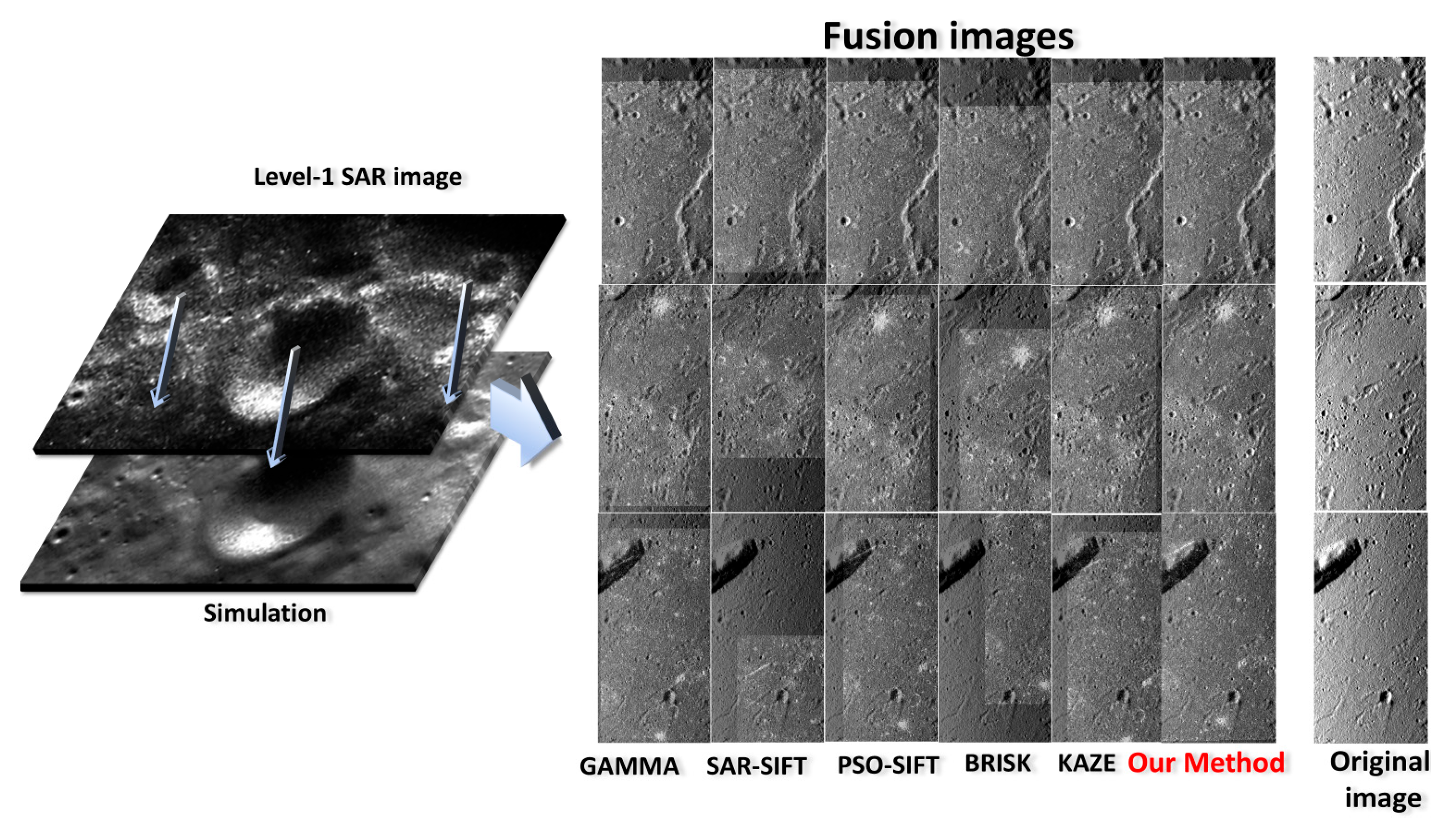
The proposed method was applied to the entire Mini-RF S-band dataset (6584 images after excluding data with equipment malfunctions) and the Mini-SAR S-band dataset (735 images after similar exclusions). The accuracy and performance of the registration method were evaluated on a global scale, and its robustness was verified by comparisons with Level 2 data processed with other methods.
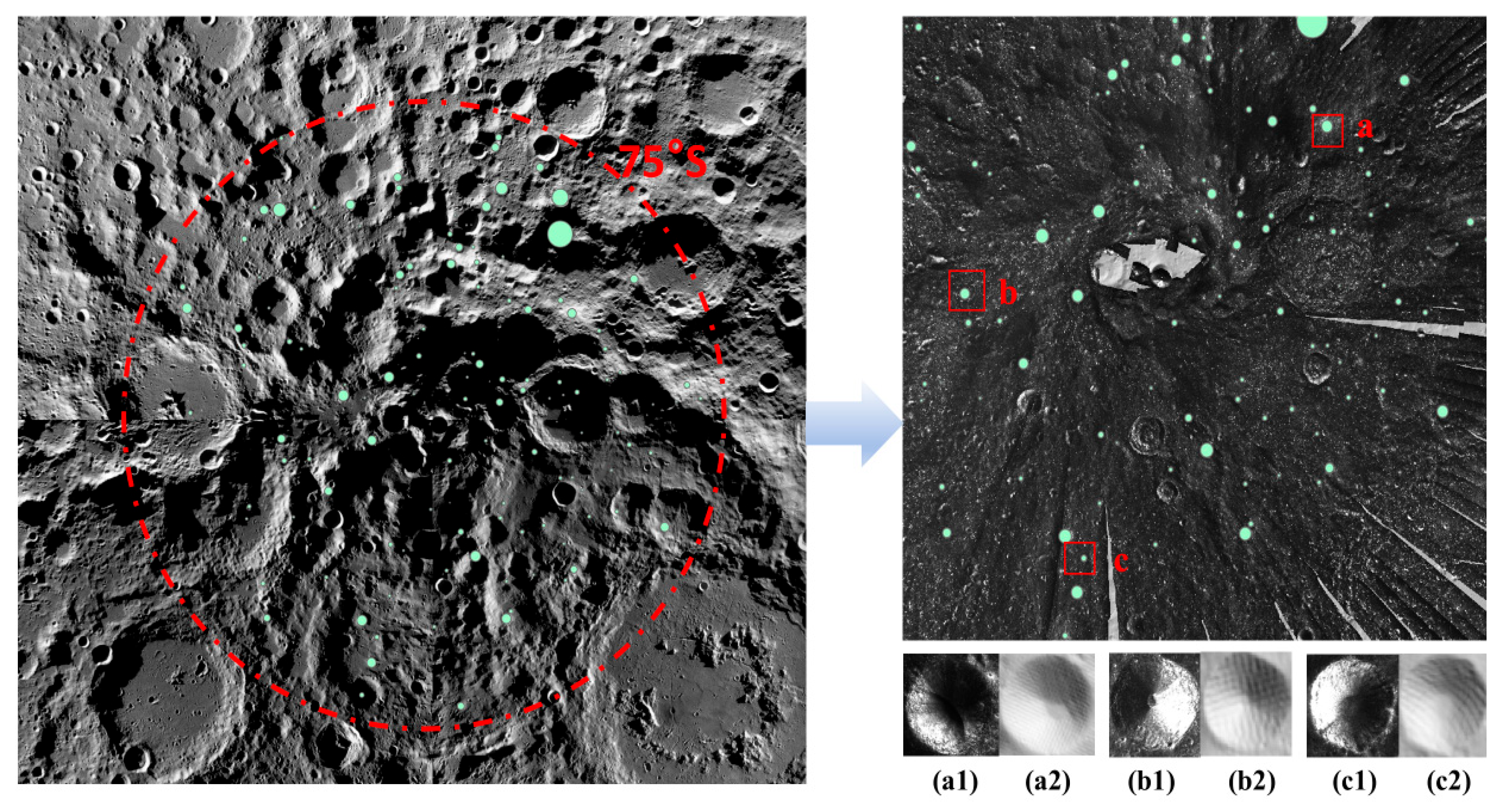
After completing the accuracy assessment, the registered full-moon SAR datasets were completed. The registered data were further utilized for the circular polarization ratio (CPR) analysis of anomalous craters in the lunar South Pole. The results demonstrate that the improved registration process significantly impacts CPR analysis, enabling the correction of average CPR statistics for geological targets such as craters, thereby enhancing the reliability of the interpretations.
This article is divided into five main parts: Introduction (
Section 1), Dataset (
Section 2), Methodology (
Section 3), Experiment Results and Discussion (
Section 4) and Conclusions (
Section 5). In the Dataset part (
Section 2), the source and characteristics of the remote-sensing datasets used in the experiment are introduced. In the Methodology part (
Section 3), the basic framework and theories of the proposed method are discussed. The Experiment Results and Discussion section (
Section 4) mainly discusses the validation process of the algorithm’s effectiveness, robustness, and the results of data analysis.
3. Methodology
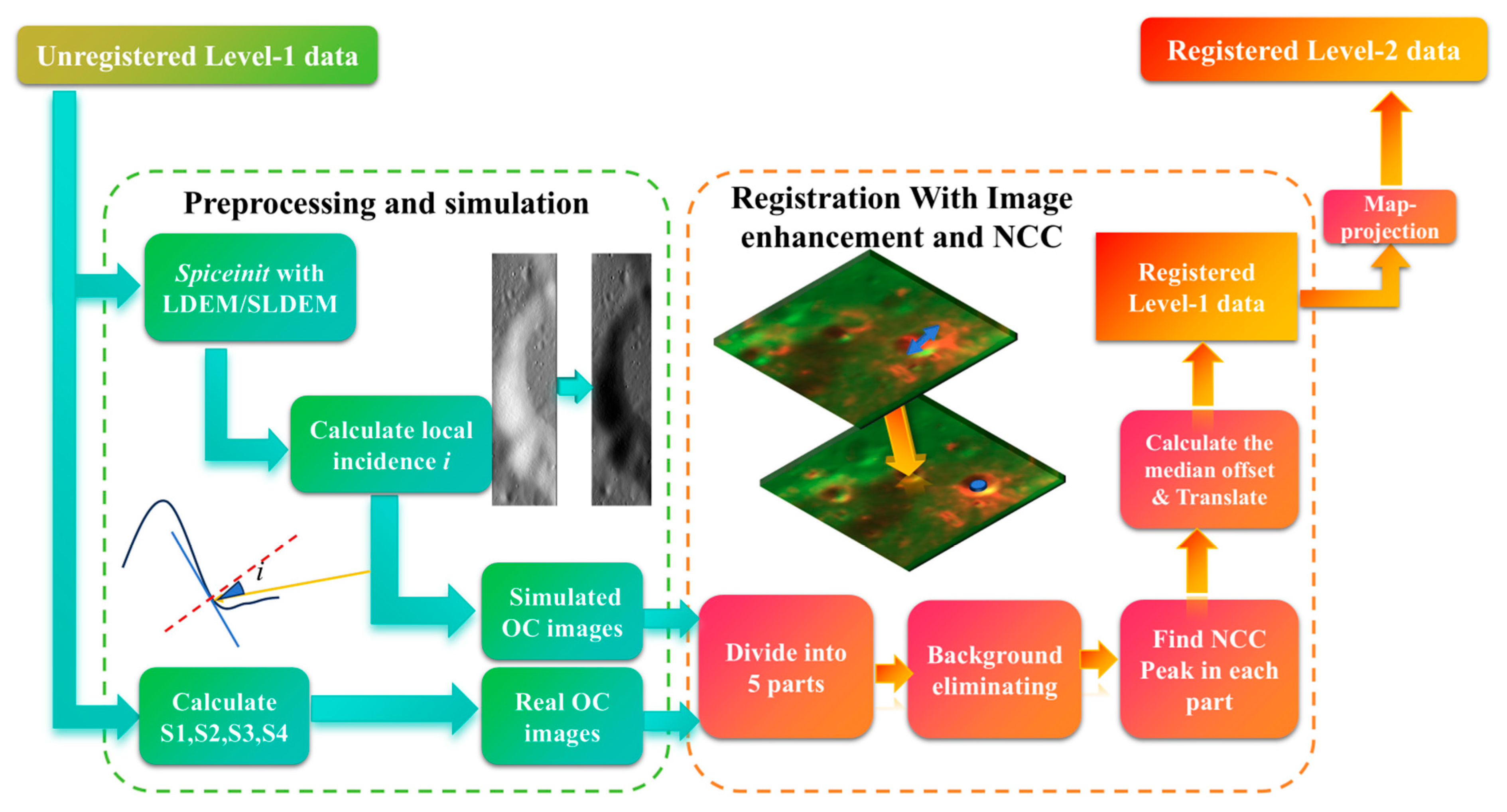
In order to realize the registration of SAR images to lunar maps, the proposed method is structured into two key parts: (1) preprocessing and simulation, which includes Stokes parameter computation and simulated image generation, and (2) registration with image enhancement and NCC, which involves image dividing, image enhancement focusing on background eliminating, and estimating the offset with co-registration, as illustrated in
Figure 1.
These stages in
Figure 1 collectively address the challenges in the lunar SAR data registration, ensuring improved alignment and reliability and obtaining the registered Level-1 lunar SAR data. To produce registered Level-2 data, the third step includes orthorectification and map projection and is implemented through the existing R-D positioning algorithm. After the above steps, the final registered Level-2 data product is completed.
3.1. Preprocession and Simulated Image Generation
The preprocessing step mainly follows the instructions provided by USGS, with several additional steps included in the workflow, including the generation of real/simulated OC images.
Using hybrid polarimetric echoes from Mini-RF and Mini-SAR, the Stokes parameters can be derived to describe the polarization states of the waves received. The four Stokes parameters
S1,
S2,
S3, and
S4 can be expressed as demonstrated in (1).
ERH and
ERV represent the horizontally and vertically polarized complex components from the right circularly polarized signal transmitted. And
indicates the conjugate of
ERV in the complex domain.
With the Stokes parameters, same-sense (
) and opposite-sense (
) circular echoes and the circular polarization ratio (CPR) can also be calculated as shown in (2).
The OC component better reflects the variations in scattering intensity caused by terrain changes. As a result, the OC component of the SAR image is calculated for use in subsequent processes. Then, the reversed R-D model is applied to produce the back-projection of the LDEM and SLDEM data within the SAR image’s coverage area with orbital information [
28].
The R-D location model is shown in Function (3)
. R/
represents the coordinate of the ground point in the range-Doppler field.
represents the coordinate of the satellite, while
represents the ground point in the geocentric coordinate system. The
z information is usually provided by the DEM. By solving the equation for an approximate solution, the precise mapping relationship from the SAR image domain to the geocentric coordinate system can be obtained. And the reversed relationship can generate the DEM image in the SAR image domain. With the local DEM data, the local incidence angle,
i, which is the angle between the incident wave and the vertical direction of the local terrain slope (shown in
Figure 1) for the radar imaging range is derived from the back-projection.
After preprocessing, the simulation step generates a simulated SAR image to serve as a registration reference. The OC component is selected as the reference because it contains richer information about terrain variations. To perform the registration, a simulated SAR image must first be prepared. Thompson’s backscattering model for 13 cm radar waves is employed to create these radar image simulations [
29]. The formula used to relate the local incidence angle
i (in degrees) to the simulated backscattering intensity is shown in Equation (4).
represents the final simulation result of the OC component, which consists of the low-angle specular component
and the high-angle specular component
.
After the simulation step, the simulated OC image is used as the fixed reference for registration. It is necessary to mention that up-sampling or high-definition (HD) enhancement is not included in this process, as experiments have shown that up-sampling does not provide reliable improvements in registration accuracy. Instead, it only leads to an exponential increase in computational complexity.
3.2. Image Enhancement and Correlation Registration
Before proceeding to the registration step, it is necessary to determine the registration method. The choice of method depends on the transformation model of the offset. Assuming that the back-projection and simulation processes accurately capture the correct incidence direction, the offset between the real SAR image and the simulated image can be represented as a rigid transformation characterized by an along-track offset (δy) and a cross-track offset (δx).
After transformation analysis, since there is no distortion or rotation between the two images, the correlation coefficient is chosen as the metric to calculate the offset because it is more efficient and not dependent on specific image texture information, such as corner points, edges, and gradient variation.
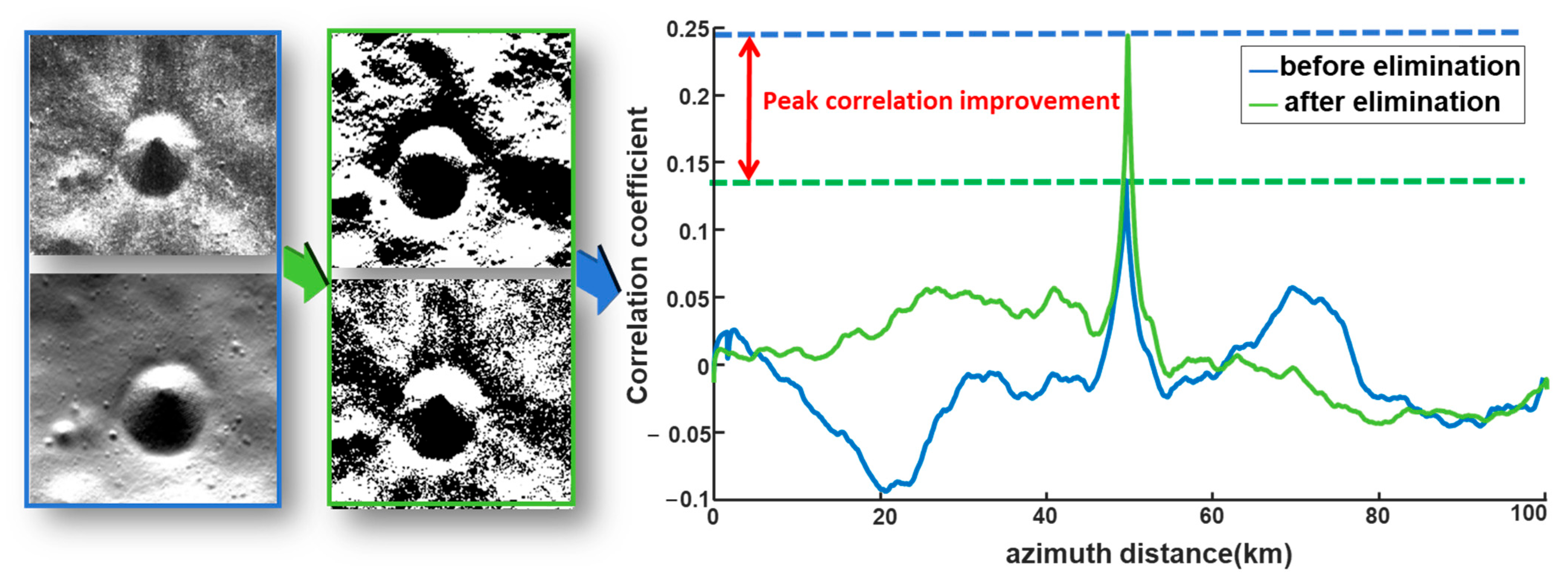
Before applying the registration method, specific image enhancement techniques are performed on the fixed and reference images to improve the final registration performance. Since the two images differ in background and texture in certain areas, image enhancement is necessary to increase the correlation between the real OC image and the simulated one.
As shown in Equation (5), the image is first multiplied by a mask (
), which is designed to cover the no-data regions of the real SAR image to exclude the no-data region in the simulated image and reduce computational load. To enhance edge features, such as crater rims and linear structures, a background elimination procedure inspired by the image pyramid method [
30] is applied to reduce the influence of the local background. This process involves down-sampling the image, followed by up-sampling it back to its original resolution, effectively performing a low-pass filtering operation to generate a background image (
). The background image is then subtracted from the original image (
) to produce an enhanced foreground image (
). As illustrated in
Figure 2, the improvement achieved by removing the image background is significant. The peak correlation response is enhanced by approximately 66% after background elimination.
In this procedure, the down-sampling ratio affects the final performance of the correlation and is related to the local texture information of the image. To select the best ratio for the method, 20 views of sample images are chosen to undergo background elimination with a ratio of 5:1, 10:1, 20:1, and 50:1. The average correlation peak response improvement is shown in
Table 1. According to the result, 10:1 is chosen because this rate is the most stable and effective in performance. To further prove this conclusion, 100 views of Mini-RF data from the North Pole, 100 from the South Pole, and 150 from the mid-latitude area were selected to examine the matching rate of SAR data from different regions of the Moon. As shown in
Table 2, as the down-sampling ratio increases, the performance of the image enhancement in mid-latitude regions rapidly declines. This phenomenon exists because an excessively high down-sampling ratio may amplify the impact of striping noise, causing a sharp decline in the enhancement’s performance in mid-latitude regions. The ratio of 10:1 is the most stable in its performance for the three kinds of areas mentioned above.
After the enhancement step, correlation-based registration is applied. For Mini-RF data, the fixed and moving images are first divided into five equally sized sections. The position of the peak correlation ([xp, yp]) between the original enhanced image and the simulated image is then calculated. The offsets ([δx, δy]) are determined by subtracting the center of the correlation image from [xp, yp].
Offsets are calculated for all five sections, and any results exceeding 10 km (330 pixels) are deemed invalid and discarded. The median of the remaining valid offsets is selected as the overall offset for the entire image. Finally, the translate function in ISIS is used to eliminate the calculated offset.
For Mini-SAR data, the overall scheme is similar to that of Mini-RF, with the following differences. Due to Mini-SAR’s relatively low resolution of 150 m/pixel, the effective information for registration primarily pertains to large-scale structures. To preserve the integrity of these structures, the images are divided into three sections instead of five. Additionally, the background elimination step is omitted.
After the registration, the co-registered Level-1 image is mapped by the function
cam2map from ISIS [
28]. The map product could be used to generate products for analysis.


 ,
, 


