1. Introduction
With the continuous development of space satellite technology, remote sensing video satellites have achieved multi-object tracking (MOT) of moving vehicles on the ground. The MOT of moving vehicles has a wide range of applications in fields such as security monitoring [
1], motion analysis [
2], and traffic control [
3]. Furthermore, due to the large amount of data in satellite videos and the high latency of transmission to the ground, real-time, on-satellite processing is of great practical significance [
4,
5,
6]. With regard to devices for implementing on-satellite algorithms, commercial, off-the-shelf (COTS) Graphics Processing Units (GPUs) or Central Processing Units (CPUs) are difficult to use due to issues related to power consumption, spatial radiation, and extreme temperatures [
7,
8]. Application-Specific Integrated Circuit (ASIC) processing chips are expensive due to their single-function nature and are not suitable for algorithm deployment or adaptation to different scenarios [
9], while Field-Programmable Gate Arrays (FPGAs) are highly versatile and portable and may be used in on-satellite applications [
10].
In real-time videos captured by remote sensing satellites, vehicle targets are small and exhibit little texture information due to large imaging distance and coverage [
11]. It is difficult to apply traditional MOT algorithms to remote sensing vehicle tracking in natural scenes (using, e.g., surveillance cameras and video recorders) or aerial scenes (using, e.g., drones and aircraft) [
12]. Remote sensing MOT algorithms can be divided into traditional algorithms and deep learning-based algorithms [
13], while the frameworks of remote sensing MOT algorithms can be divided into detection–association frameworks and the joint detection–association frameworks [
14]. The detection–association framework has two steps—moving target detection and target association—which are independent of each other. In a joint detection–association framework, detection and association are combined and the association effect is improved via predictions of target displacement in the detection stage. In this framework, the complexity and computational complexity of the algorithm are increased, which is not conducive to on-satellite implementation.
In recent years, deep learning-based remote sensing MOT algorithms have made great progress [
15]. Xiao et al. [
16] applied the recognition framework to remote sensing MOT through a two-stream framework [
17], resulting in DSFNet. DSFNet effectively recognizes moving target information; however, five consecutive frames at a time are required to be processed to obtain a single frame of a moving target. Zhang et al. [
18] proposed a bidirectional MOT framework based on trajectory criteria (BMTC). In this BMTC, the impact of performance degradation in the detection stage is reduced, and it predicts the target trajectory while simultaneously backtracking the trajectory of invalid segments. However, the trajectory backtracking process greatly increases the computational complexity, and the frame rate implementation is only 0.148 fps using a TITAN X GPU; this is far from achieving real-time detection. Zhao et al. [
19] proposed a mask propagation and motion prediction network (MP
2Net), which enhances the characteristics of small targets and combines implicit and explicit motion prediction to improve multi-target tracking. However, due to its complex network structure, MP
2Net only achieves a tracking speed of about 3 fps on a Titan RTX GPU, which does not meet real-time tracking requirements. Deep learning-based MOT algorithms for remote sensing can model target and image features through continuous training, but this relies on high-performance hardware such as GPUs or Tensor Processing Units (TPUs). Satellite power supply and cooling systems cannot cope with the use of such equipment [
20]. At the same time, on-satellite MOT implementation requires quantization and model pruning, which will affect the accuracy of the models and require more tuning and training [
21].
Traditional methods for implementing MOT algorithms for remote sensing mainly use the detection–association framework. In terms of the detection method, Ahmadi et al. [
22] proposed moving vehicle detection, tracking and traffic parameter estimation method (DTTP), which removes the background using the frame difference method to extract moving targets and uses a neighborhood search method to associate the target, while Wei et al. [
23] proposed a detecting and tracking framework (D&T), which uses an exponential probability distribution to distinguish potential vehicles from noise patterns based on modeling the local noise. The use of D&T improved moving vehicle detection. In terms of the association method, Zhang et al. [
24] proposed a bi-level K-shortest method for constructing spatio-temporal grid flows for association. The extracted trajectory can skip bad detections. These traditional algorithms for remote sensing MOT have significant advantages for solving specific problems (e.g., background noise, occlusion, and lost tracks) compared to deep learning-based methods. The use of these methods increases the depth of the model and the amount of computations, and more operations are required during processing. The traditional method is more suitable for application on satellites with limited power consumption and computing power.
Due to the limitations of on-satellite equipment, most MOT algorithms used on satellites have, in recent years, adopted a detection–association framework containing a traditional algorithm. Liu et al. [
25] used a Zynq FPGA to detect and associate targets, using dynamic background difference and a Kalman filter, respectively. However, the Programmable Logic (PL) part of the FPGA is only used to implement the preprocessing algorithms, while both detection and tracking algorithms are implemented on the Processing System (PS) side. The acceleration effect of PL is limited, and real-time processing cannot be achieved. Han et al. [
26] achieved tracking through a shape center extraction algorithm, and they then implemented the algorithm in an FPGA-based space-embedded system. In this method, only the largest moving target is tracked without background removal; it is not suitable for complex moving backgrounds. Su et al. [
27] proposed using an improved local contrast method and the Kalman filter to detect and associate potential targets, using the difference in motion states to suppress fixed stars. Then, they implemented the algorithm on an FPGA and DSP. However, this method is aimed at targets in deep space with a simple background and is unable to track moving vehicles in complex moving backgrounds. Overall, recent research on the on-satellite implementation of MOT algorithms for remote sensing is still limited to the implementation of traditional algorithms for deep space backgrounds. In this paper, we propose an MOT algorithm for moving vehicles in complex moving backgrounds and implement the algorithm on a satellite to achieve real-time MOT.
Based on the above analysis, it can be observed that traditional MOT algorithms can effectively solve the following problems related to deep learning-based MOT algorithms when implemented on satellites:
(1) Dataset limitations
The basic framework of deep learning-based MOT algorithms features two steps: training and inference. During the training phase of the neural network, a large amount of labeled data is required for training. The dataset’s quality and the training method directly affect the inference results. However, there is currently a small amount of high-quality labeled datasets for on-satellite MOT, and labeling multiple small targets is costly. Traditional MOT algorithms rely on predefined target types and extract the features of the targets to achieve MOT in the absence of these datasets.
(2) Computational scale and on-satellite implementation capabilities
The performance of deep learning-based MOT algorithms can be further improved by increasing the size of the neural network, but this also leads to a sharp increase in the number of calculations. The implementation of a large-scale neural network will lead to substantial processing time. Moreover, the deployment of such a network may be impractical due to the power consumption and resource constraints of on-satellite equipment. The actions of moving equipment (e.g., camera turntables and propulsion devices) are highly dependent on real-time performance, and the images need to be processed in real time to control the attitude of the satellite.
(3) Traceability and reliability
Deep learning models have a range of structures and connections, and there is no clear conclusion yet on the specific role of certain parts. The traceability and reliability of results are crucial in critical tasks such as satellite control. Traditional MOT algorithms are based on clear target features and work steps, and the results of each step can be clearly explained, making them more suitable for on-satellite processing tasks.
The main contributions of this paper are two-fold:
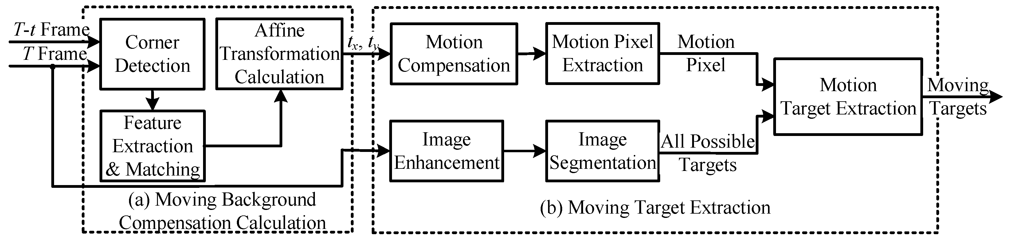
(1) We propose an MOT algorithm with a detection–association framework designed for complex moving backgrounds in remote sensing scenarios. The algorithm employs corner feature matching and the neighbor pixel difference method for background compensation and motion pixel extraction. The extracted motion pixels enable precise bounding box generation for moving targets. For target association, the Jonker–Volgenant (JV) algorithm is adopted to solve the linear assignment problem (LAP) efficiently, ensuring accurate and continuous MOT.
(2) A pixel-level stream processing mode and a cache access processing mode are proposed to optimize the on-satellite implementation of the MOT algorithm. These modes leverage pipeline and parallel processing to enhance processing efficiency and real-time performance, aligning with the characteristics of the satellite hardware and sensor output. The complete algorithm is successfully implemented on-satellite, achieving a comparable tracking performance to existing algorithms while ensuring real-time applicability.
In this paper, we propose an MOT algorithm for moving vehicles in complex moving backgrounds and apply the tracking algorithm onboard a satellite to achieve real-time multi-object tracking. In the detection stage, we use feature matching to obtain the background’s motion information. Then, we use neighboring pixel differences to segment the motion pixels. Finally, to eliminate the background noise, we fuse the motion pixels with the enhanced raw image to obtain complete moving-vehicle targets. In the association stage, we use the Kalman filter and the LAPJV matching algorithm to predict and associate the target, respectively. In addition, we implement the algorithm using an on-satellite FPGA and optimize the algorithm for pipelining according to the on-satellite equipment and sensors. The algorithm processes while the sensor reads. The joint software and hardware design can accelerate the processing speed of the algorithm and improve its real-time performance; the on-satellite processing method proposed in this paper can achieve real-time processing at 1024 × 1024 px@47 fps.
The remainder of this paper is structured as follows.
Section 2 details the design of the tracking method,
Section 3 introduces the hardware implementation,
Section 4 presents the experimental results,
Section 5 is discussions and limitations, and
Section 6 provides a conclusion.
3. Hardware Implementation
3.1. Overall Hardware Design
The multi-object vehicle tracking algorithm for moving backgrounds proposed in this paper was implemented on a satellite, where real-time MOT processing is entirely implemented by an FPGA. The structure of the proposed on-satellite system is shown in
Figure 4, and it mainly includes input and output interfaces, a global control module, a pipeline control and status acquisition module, a DDR cache, and image processing modules. The input interface receives the real-time data from the sensor and converts the pixel-by-pixel readout from the sensor into an image data stream that is sent to the image processing module for processing. This data stream is also stored in the DDR cache. The output interface outputs the target tracking results, which can be used by the satellite to control the turntable and transmit result; thereby, autonomous control of the remote sensing satellite is achieved. The global control module controls all system functions and obtains the system status for telemetry and remote control, while the pipeline control and status acquisition module controls the pipeline status of the image processing module and obtains the working status of each module. The DDR cache buffers the results of the image processing module and also buffers multiple image frames. The image processing modules are the compensation calculation module, the background compensation and target detection module, and the multi-target association module. These three modules are processed in a pipeline, and read-and-write interactions are performed with the data in the DDR cache to achieve real-time image processing.
The internal design of the submodule has two modes: the pixel-level stream processing mode and the cache access processing mode. The pixel-level stream processing mode is used to scan and process complete image data, and its internal structure is shown in
Figure 5a, showing that it includes a row buffer, versatile RAM, and computational core. The input image data are cached in real time in the
k row buffer according to the size of the calculation kernel
. The row buffer consists of a chain of shift registers made up of block RAM, and the output buffer contains the pixels of the calculation kernel as a new pixel
i is input. The row buffer greatly simplifies image neighborhood processing, reduces the on-chip memory footprint, and also satisfies pixel-by-pixel input and output processing. The submodule also contains versatile RAM, which is designed with different functions, such as convolution kernel, filter kernel, or temporary data storage. Such data include the location of the matching points and sampling points storage, and the functions can be used after obtaining the
calculation kernel.
The computational core is designed with different computational functions according to different submodules, and the computational core can be assembled and reused according to the design of the algorithm.
The other design mode is the cache access processing mode, which can be used to perform various complex operations on the data in the cache and write the results back to the cache. Its internal structure is shown in
Figure 5b, and it includes multi-frame or multi-target cache, load and save module, and complex computation module. The cache may be composed of on-chip block RAM or DDR, and the cache configuration can be changed according to the amounts of calculations and data. The load and save module adjusts the read and write timing according to the cache type and calculation mode to reduce the effect of the interface bandwidth. The complex computation module implements a variety of processing tasks and performs on-chip linear tasks such as prediction, matching, and lookup in multi-object tracking algorithms. This mode is similar to that of the traditional processing method, but by decomposing complex computations into finer granularities, the demand for interface bandwidth is reduced, preventing the processing from being affected by real-time bandwidth bottlenecks. The following is a detailed introduction to each module of the algorithm implementation.
3.2. Compensation Calculation
In the compensation calculation module, the transformation matrix
between
T frame and
frame is calculated by acquiring and matching the corner features of an image, i.e., the compensation information
of the moving background. The structure of the compensation calculation module is shown in
Figure 6, and it includes five submodules: corner detection, main direction calculation, feature description extraction, feature matching, and transformation matrix modules. The corner detection submodule extracts the corner points of the current frame image, while the main direction calculation submodule calculates the main direction of the corner points. The feature description extraction submodule extracts rotation-invariant corner features according to the main direction and stores the corner features in the DDR cache at the same time. The feature matching submodule matches the corner features of frame
T with those of remtheframe
, while the transformation matrix calculation submodule calculates the affine transformation matrix of the image according to the matched feature points and obtains the translation amounts
and
.
The corner detection submodule performs gradient calculations, Gaussian smoothing, and thresholding and outputs the maximum value. It extracts the corners from the current frame by thresholding the smaller eigenvalue
of the gradient covariance matrix
and then using non-maximum suppression (NMS). The gradient covariance matrix
is shown in Formula (
6):
where
and
represent the image gradients in the
x and
y directions, respectively, which are obtained by the Sobel operator after Gaussian filtering. Gaussian smoothing is performed by convolving the calculated gradient magnitude with a
Gaussian kernel, using a standard deviation of 0.5 for the Gaussian function.
The main direction calculation submodule performs neighborhood extraction, neighborhood gradient averaging, and rotation angle calculation. This submodule obtains the main direction of the corner points in the image. The feature direction of the central pixel
is calculated using the information gained from 45 sampling points around the corner point
, as shown in Formula (
7).
where
are the coordinates of the sampling points,
and
are the pixel values after Gaussian filtering, and
is the number of sampling points.
The feature descriptor extraction submodule performs sampling point selection and grayscale comparison and outputs features. This submodule adjusts the sampling point position of the feature descriptor according to the feature direction
, obtains a feature descriptor with rotational invariance, and stores the coordinates of the corner point and the corresponding feature value in the DDR cache. The feature
of the corner point is extracted using information from 43 sampling points around the corner point
. The calculation of
is shown in Formula (
8):
The feature matching submodule performs feature loading, region selection, and similarity comparisons. By obtaining the corner coordinates and feature values of the current, T, and previous, , frame, the similarity between the two frames is calculated to obtain the matching point pair. The area around the feature points in the current frame is filtered according to the background motion speed and the frame rate of the image sensor. The search neighborhood range needs to be adjusted according to the task; a typical value is centered on the corner feature. The FREAK feature descriptor of the corner feature is a 512-bit vector. If the number of corner features that are the same in the two frames is greater than 400 bits, corner feature matching is considered successful. The similarity calculation uses a circuit addition tree in parallel to improve the processing speed.
The transformation matrix calculation submodule performs random selection, matrix calculations, error calculations, and best selection. The best transformation matrix is obtained by continuously randomly selecting matching points and calculating the error. The RANSAC algorithm is used to randomly sample point pairs from matching point pairs; this random sampling can exclude outliers when performed a large number of times, bringing the calculation result closer to the correct transformation matrix. Correct matching point pairs and abnormal matching point pairs can then be obtained. The specific process is as follows:
(1) First, three matching point pairs are randomly sampled from matching point pairs and , and a conversion matrix is calculated for this set of sampled point pairs. Set to represent the coordinates of feature points in the current frame T, and to represent those in the previous frame . An 11-bit linear feedback shift register (LFSR) is used to generate pseudo-random numbers.
(2) The coordinates of the points in set are calculated after transformation using the transformation matrix calculated in step (1).
(3) The error between the coordinates calculated in step (2) and the coordinates of the matched point pairs in set is calculated. If the error is less than the set threshold, the point pair is an interior point under the current transformation matrix; if it exceeds the threshold, it is an exterior point. The number of interior points under this transformation is counted.
(4) Steps (1) to (3) are repeated until the maximum number of iterations is reached. Select the transformation matrix with the most interior points.
The complexity of the RANSAC algorithm depends on the set number of iterations. The higher the number of iterations, the more accurate the transformation matrix calculation, but the longer the calculation time. Therefore, a reasonable number of iterations is required for the algorithm to run more efficiently. The theoretical minimum number of iterations
N is calculated [
40] as shown in Formula (
9).
where
s represents the number of samples, which is set to 3 when calculating the transformation matrix, indicating that three sampling points are selected.
p represents the probability that at least one of the three sampling points is an interior point, and
p is generally set to 0.99.
represents the probability of an exterior point being in the matched point pair. Seting
,
, and
leads to
. Seventeen point pairs were randomly selected to calculate the optimal affine transformation matrix
with the maximum number of interior point matches.
3.3. Background Compensation and Target Detection
The background compensation and target detection modules begin calculating in parallel with the compensation calculation module. Background compensation requires the image translation parameters
in the affine transformation matrix output by the compensation calculation module, and the background compensation and target detection modules process
frames and
frames.
frames are written to the DDR cache simultaneously while the compensation calculation module is operating. The DDR has a cache of the original image of frame
. The background compensation and target detection modules obtain the original images of frames
and
and the affine transformation matrix of frame
from the DDR cache. The structure of the background compensation and target detection module is shown in
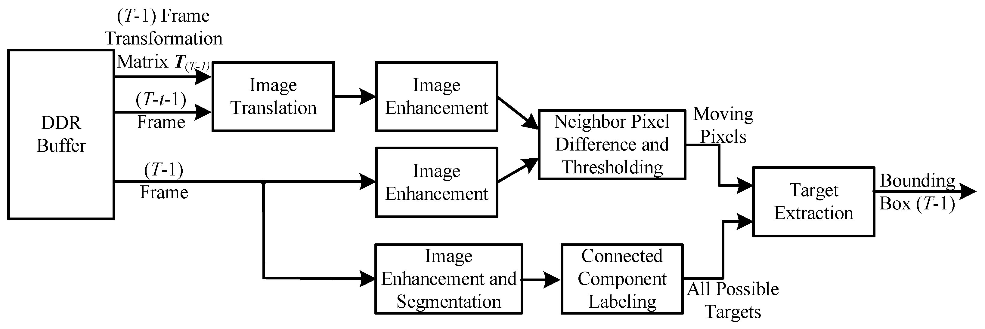
Figure 7, and it includes six submodules: image translation, image enhancement, neighborhood pixel difference and thresholding, image enhancement and segmentation, connected domain marking, and target extraction modules.
The frame image is background-compensated after image translation using Laplace enhancement. The neighborhood pixel difference and thresholding submodule subtract the pixel in the enhanced frame from each pixel in a neighborhood in the background-compensated frame to obtain the minimum value, which is then compared with the threshold. If it exceeds the threshold, the pixel is a motion pixel, and the motion pixel image is output.
At the same time, the frame image is Laplace enhanced, and after subtraction from the original image, it is segmented according to the threshold value. The connected domain labeling submodule assigns different label numbers to the connected domains in the segmented image, and all possible target images are output.
The target extraction submodule calculates the bounding box of the possible target image and filters out the bounding box of the moving target that contains the motion pixel. Because all possible target images have a large number of connected domains, this calculation is time-consuming. Therefore, in this paper, we use the single-scan connected-component analysis (CCA) algorithm for all possible target images :
(1) The input image is input row by row, and each connected component that appears in a row is assigned a tag from 1 to the maximum number of columns, ensuring that there are no duplicate tags between adjacent rows.
(2) The tags for the same connected component in each row are stored in the form of a linked list, including a head list, a next tag list, and a tail list. In addition, there is a motion pixel list, where the tag in the list is set to 1 if the pixel at the corresponding position of a tag is a motion pixel in .
(3) During the scanning process, the bounding box coordinates of the tags in the linked lists belonging to the same connected domain are merged, including the upper, lower, left, and right coordinates.
(4) After each current connected-component scan is complete, and if the current scan of the connected domain ends here and the connected component corresponds to a moving pixel, the bounding box accumulated for this connected domain is output; if the current scan of the connected domain does not end, the bounding box coordinates corresponding to the current mark are re-initialized after merging.
(5) After inputting all possible target images , the bounding boxes of all connected components containing moving pixels are output.
The CCA algorithm is performed in a single scan and can immediately obtain the bounding boxes of moving objects, even if the image has not been fully inputand the connected components have already ended.
The bounding boxes of the background compensation and object detection module are output in real time as the data streams of the frames and frames are read from the DDR cache. Once a bounding box is detected, which meets the requirements, and the connected components end, the bounding box is output in the next clock cycle. The background compensation and object detection modules are designed to perform single scans using our proposed pixel-level stream processing mode, which avoids multiple reads from the DDR cache, reduces the amount of bandwidth used by the DDR interface, and improves the processing speed. It can also be used in parallel with the compensation calculation module.
3.4. Multi-Target Association
In the second stage of the entire MOT process, moving targets are associated with multiple frames and target IDs are assigned for achieving target tracking. The structure of the multi-target association module is shown in
Figure 8, and it includes five submodules: IoU calculation, ID assignment, Kalman prediction, Kalman correction, and target feature and Kalman parameter caching modules.
In order to achieve pipelined parallelism, the multi-target association module processes the moving targets of frame
when the sensor outputs frame
T. First, the target information and Kalman filter parameters of frame
are obtained from the target feature and Kalman parameter cache, and then the Kalman prediction submodule predicts the target position of frame
. The IoU calculation module calculates the IoU between the moving target of frame
and the predicted target of frame
to obtain the IoU matrix
, as shown in Formula (
4). The ID assignment module calculates the optimal assignment, assigns the ID from the target of frame
to frame
, and outputs the tracked target. At the same time, the Kalman correction submodule is used to adjust the parameters of the Kalman filter and store them in the target feature and Kalman parameter cache.
The results of ID assignment are separated into three categories. The first category is for results in which the target box in the current frame is successfully associated with the tracking box. If the similarity is greater than the set threshold, it is considered to be a valid match, and the tracked ID number is assigned to the current tracking box. If the similarity is less than the set threshold, it is an invalid match, and the tracked ID number will be discarded. The second category is for results in which the target box in the current frame is not successfully associated with the tracking box. This indicates that the target box in the current frame is a newly emerged target, and a new ID number is assigned to this target at this time. The third category is for results in which the tracking box is not successfully associated with the current target box. This indicates that the tracking box does not have a corresponding target in the current frame, that is, the target is lost, and the ID number of the tracking box is discarded at this time.
After the above process, the target box of the current frame is assigned to that of the previous frame, and the ID number corresponding to the target box of the previous frame is assigned to the target of the current frame to continuously track the target.
The MOT algorithm proposed in this paper is implemented in a pipelined parallel manner. In the compensation calculation module, the pipelined calculation is implemented by means of a row buffer, which reduces the delay in the output of feature descriptors, while in the background compensation and target detection module, motion pixel extraction is achieved using the neighbor pixel difference method, effectively removing background interference. Moving target extraction is implemented using the single-scan CCA, which reduces repeated reads and writes to the DDR cache. In the multi-target association module, the target features and Kalman parameters of each tracked target are independently cached on-chip, which improves the speed of target association. The algorithm implementation module adopts a pixel-level stream processing mode and a cache access processing mode, which implements the entire processing algorithm using the satellite’s equipment.
5. Discussion and Limitations
5.1. Discussion of Experimental Results
The on-satellite MOT algorithm proposed in this paper is implemented at the sensor’s edge to continuously track multiple targets and extract their trajectories. The FPGA can also control the turntable to further continuously track and locate individual targets or groups of targets whose motion trajectories meet specific characteristics. The moving-background compensation algorithm proposed in this paper can effectively remove the background motion caused by the relative motion of the turntable and the satellite to the ground, enabling on-satellite real-time MOT.
First, we tested the algorithm on the publicly available SkySat dataset; the results are shown in
Table 1. Compared with traditional algorithms [
22,
23,
24], the proposed MOT algorithm led to improvements in terms of MOTA, IDF1, IDP, and IDR. In particular, the MOTA improved from 48.1% to 69.9%, an increase of about 22%. The multi-object tracking algorithm proposed in this paper is based on a traditional algorithm. With the same static dataset, the tracking metrics greatly improved compared to those of other traditional algorithms.
Compared with the latest deep learning-based object tracking algorithms [
18,
19], the proposed algorithm achieves an IDP of 84.3%, 2.8% higher than 81.5%, and the number of MTs increased from 126 to 149. MP
2Net [
19] combines implicit (IMP) and explicit (EMP) motion prediction strategies. IMP can enhance targets with inconspicuous motion features, while EMP uses predicted displacement information between target frames to suppress false positives in motion target tracking and compensate for missing detections. Therefore, MP
2Net can detect more moving targets and thus obtain higher MOTA, IDF1, and IDR values. However, its multiple complex network structures make the inference process extremely cumbersome, and tracking results cannot be output in real time. Compared with the latest deep learning-based object tracking algorithms, the proposed algorithm can be implemented onsatellites with only a small deterioration in tracking metrics.
The MOT algorithm proposed in this paper uses the neighbor pixel difference method to simultaneously detect motion pixels and extract complete targets from the original image. This combination can effectively screen out complete moving targets, effectively improving the MOTA compared to traditional algorithms. The extraction of complete moving targets also helps the effective matching of Kalman prediction and LAPJV matching during the matching stage, which leads to a superior IDF1 value.
Next, we altered the displacement of the selected region in the dataset to generate several test video sequences with a moving background. The MOTA and IDF1 values with respect to the speed of movement are shown in
Figure 12. The video sequence is unified with the public dataset at 300 frames, and there are fewer scenarios where the tracked target is occluded. When the background movement speed is 0 px/frame, the algorithm proposed in this paper is better than MP
2Net [
19] in regard to both MOTA and IDF1 values. As the background motion speed increases, the MOT algorithm proposed in this paper can effectively track the target in a moving background and maintain its superior tracking metrics.
The end position of the selected region of the dataset is different at different background motion speeds, which leads to a difference in the total number of targets. Therefore, the evaluation metrics at a background motion speed of 1.5 px/frame are better than those at 1.0 and 2.0 px/frame, and MP
2Net [
19] performs similarly to the algorithm proposed in this paper.
Analyzing the overall trends, it is shown that the algorithm proposed in this paper has a good tracking effect in the presence of a moving background. The addition of an algorithm to compensate for background motion can help to accurately obtain the background offset based on the motion relationship of feature points. The moving background can thus be removed, and the moving vehicle target is effectively retained.
Then, we aslo visualized the results of motion target detection, as shown in
Figure 13. MP
2Net [
19] mistakenly identifies the background motion as a moving vehicle target, generates a false alarm, and also ignores vehicle targets moving at a similar speed to the background motion, resulting in missed detections. The moving target detection algorithm we propose can effectively detect moving vehicle targets in the presence of background movement.
Based on the evaluation results using the public SkySat dataset, the algorithm proposed in this paper has good MOT results in both static and dynamic backgrounds. The algorithm compensates for and removes the background and extracts the moving target to achieve effective MOT.
Furthermore, we evaluated MOT using original output videos from the Jilin-1 satellite. The tracking results are shown in
Figure 14, where targets with different IDs are distinguished by different colors. The original output video of the Jilin-1 satellite exhibits clear non-linear background motion. Our proposed MOT algorithm can compensate for this moving background and track moving vehicle targets at the same time. When the speed of the moving background changes for the deep learning-based MOT algorithm MP
2Net [
19], all tracked targets are lost due to the difference between the scenes in the training dataset, and it cannot output new tracked target boxes. In real situations, the speed of the background motion changes due to the movement of the satellite camera turntable, and this change is not fixed. By training the network through deep learning methods, it cannot be adapted to multiple changing scenarios.
Finally, we compared the performance of on-satellite implementation of the algorithm with other hardware, as shown in
Table 2. In terms of application scenarios, the method proposed in this paper can be implemented on satellites to track multiple vehicle targets in complex moving backgrounds. Liu et al. [
25] and Su et al. [
27] only achieved multi-object tracking in static background scenarios concerning ships and space-based target surveillance. BMTC [
18] and MP
2Net [
19] are the latest deep learning-based multi-object tracking algorithms for remote sensing vehicles; however, they can only perform remote sensing tracking in static backgrounds. The on-satellite method in this paper can achieve a frame rate of 47 fps, which is about 4 times higher than MP
2Net’s 11 fps [
19]. In terms of power consumption, note that Su et al. [
27] performed target tracking in deep space with a simple background. Their system is relatively complex, with detection and tracking performed using an FPGA and a DSP, respectively. The total power consumption was 13 W, which is 3 W higher than that of our method, which was implemented completely using an FPGA. In terms of GPU implementation in the same application scenario, MP
2Net [
19] consumes 310 W, which is about 31 times more power than that consumed by the on-satellite method presented in this paper. Furthermore, we learned from an Nvidia official that BMTC [
18] used a GPU with a theoretical power consumption of 250 W, which is about 25 times more power than that consumed by the method in this paper.
A comparison of the comprehensive performance indicators shows that, due to the general-purpose design of the GPU and the frequent movement of data between different memories and caches, the interface bandwidth is the bottleneck of the entire implementation, which prevents the GPU from achieving its maximum performance (typical value: 350 W) and further increases in the frame rate. The on-satellite method presented in this paper is deployed at the sensor edge and directly processes the output data from the sensor. The pipelined parallel design of multiple modules for pixel-by-pixel input and output effectively increases the processing frame rate, and eliminates the bottleneck caused by frequent data transfers to meet the real-time requirements of on-satellite processing. Moreover, the background compensation algorithm proposed in this paper removes the effects of background motion in the output video at the sensor edge. The concise moving-target extraction algorithm and target matching algorithm can achieve real-time online MOT at the edge, with only a small deterioration in performance metrics.
5.2. Limitations and Shortcomings of the Proposed Method
The MOT algorithm and on-satellite implementation method proposed in this paper have some limitations and shortcomings.
First, the image output of the on-satellite sensor may be affected by jitter due to the shaking of the satellite. If a frame is jittery, the entire picture will appear to be displaced, and the calculated displacement between frames will include the amount of jitter. As compensation is performed based on the amount of displacement, the frame difference is determined to cancel out the effect of this jitter and extract the real moving vehicle target. However, the on-satellite implementation method in this paper does not feature image pre-processing algorithms such as image stabilization, and this, the jitter of target vehicles, cannot be eliminated.
Next, moving vehicles may be occluded by environmental objects such as bridges and buildings, and the movement trajectories of different vehicles may intersect. The algorithm for target association between multiple frames used in this paper transfers target IDs between frames by calculating the IoU and using an assignment algorithm. In the short term, continuous prediction by the Kalman filter can provide some occlusion resistance; however, the algorithm proposed in this paper is not optimized for scenarios with intersecting vehicle trajectories. Intersecting vehicle trajectories often occur at intersections, but for vehicles moving normally on a road, intersecting trajectories are rare. In future work, the direction vector of the vehicle’s movement can be combined with the IoU to avoid the effects of intersecting trajectories.
In addition, due to the high mobility of vehicles, they have different speeds and directions of movement. For objects with the same speed and direction of movement as both the vehicle and the background, the moving background compensation used in this paper will consider the object as background and remove it, causing the object to be lost. This may occur when a certain object or certain objects are continuously tracked by a controlled motion mechanism. This situation can be avoided by protecting the current tracked object.
Finally, the MOT algorithm proposed in this paper was designed based on manually extracted target features only. It is not universally applicable to a variety of different scenarios. The target feature extraction capability is weak, and the algorithm needs to be adjusted and adapted according to different scenarios. However, these limitations and shortcomings are typical defects of traditional algorithms. In order to adapt to more complex scenarios, more algorithm steps and processing operations need to be added, which will have a negative impact on on-satellite implementation.
In summary, although in this paper, we have implemented the MOT algorithm on a satellite in the context of moving backgrounds, the various limitations and shortcomings of the method need to be addressed by implementing more on-satellite processing algorithms. An increase in the number of these algorithms will inevitably lead to a decrease in processing speed and an increase in resource usage. Trade-offs need to be made between various metrics to meet the requirements of real on-satellite applications.


 ,
, 


