Article

Robust and Adaptive Ambiguity Resolution Strategy in Continuous Time and Frequency Transfer

1
National Time Service Center, Chinese Academy of Sciences, Xi’an 710600, China
2
Key Laboratory of Time Reference and Applications, Chinese Academy of Sciences, Xi’an 710600, China
3
University of Chinese Academy of Sciences, Beijing 100049, China
4
College of Electronic Engineering, National University of Defense Technology, Hefei 230037, China
5
National Key Laboratory of Electromagnetic Space Security, Jiaxing 314033, China
*
Author to whom correspondence should be addressed.
Remote Sens. 2025, 17(16), 2878; https://doi.org/10.3390/rs17162878
Submission received: 4 July 2025 / Revised: 10 August 2025 / Accepted: 15 August 2025 / Published: 18 August 2025

Abstract

The integer precise point positioning (IPPP) technique significantly improves the accuracy of positioning and time and frequency transfer by restoring the integer nature of carrier-phase ambiguities. However, in practical applications, IPPP performance is often degraded by day-boundary discontinuities and instances of incorrect ambiguity resolution, which can compromise the reliability of time transfer. To address these challenges and enable continuous, robust, and stable IPPP time transfer, this study proposes an effective approach that utilizes narrow-lane ambiguities to absorb receiver clock jumps, combined with a robust sliding-window weighting strategy that fully exploits multi-epoch information. This method effectively mitigates day-boundary discontinuities and employs adaptive thresholding to enhance error detection and mitigate the impact of incorrect ambiguity resolution. Experimental results show that at an averaging time of 76,800 s, the frequency stabilities of GPS, Galileo, and BDS IPPP reach 4.838 × 10⁻¹⁶, 4.707 × 10⁻¹⁶, and 5.403 × 10⁻¹⁶, respectively. In the simulation scenario, the carrier-phase residual under the IGIII scheme is 6.7 cm, whereas the robust sliding-window weighting method yields a lower residual of 5.2 cm, demonstrating improved performance. In the zero-baseline time link, GPS IPPP achieves stability at the 10−17 level. Compared to optical fiber time transfer, the GPS IPPP solution demonstrates superior long-term performance in differential analysis. For both short- and long-baseline links, IPPP consistently outperforms the PPP float solution and IGS final products. Specifically, at an averaging time of 307,200 s, IPPP improves average frequency stability by approximately 29.3% over PPP and 32.6% over the IGS final products.

1. Introduction

Time and frequency transfer technology plays a critical role in sustaining the global time scale based on International Atomic Time (TAI). Various techniques have been developed to achieve precise time and frequency transfer, including two-way satellite time and frequency transfer (TWSTFT), common-view (CV) and precise point positioning (PPP) techniques based on Global Navigation Satellite System (GNSS) satellites, and optical fiber link time and frequency transfer. Among these, PPP has emerged as a dominant method for time and frequency transfer due to its cost-effectiveness and capability to simultaneously determine parameters such as station coordinates and receiver clock offsets using both carrier-phase and pseudorange observations. However, in the standard PPP mathematical model, the ambiguity parameters absorb both uncalibrated satellite hardware delays and receiver hardware delays. Consequently, these ambiguities are estimated as float values. This can introduce additional errors into the estimated receiver clock offset, potentially degrading the accuracy of time and frequency transfer. To restore the integer nature of carrier-phase ambiguities, several methods of server-side products to support this process have been proposed, primarily categorized as the Uncalibrated Phase Delay (UPD) method (theoretically equivalent to the Observable-Specific Signal Bias (OSB) method [1,2,3]), the Integer Recovery Clock (IRC) or phase clock method, and the decoupled clocks method. In this study, we utilize post-processed OSB products provided by the International GNSS Service (IGS) analysis center to recover the integer properties of the ambiguities. This enables high-precision positioning and time and frequency transfer with integer ambiguity resolution, known as integer PPP (IPPP). Experiments employing IPPP time and frequency transfer techniques with post-processed IPPP products have demonstrated the achievement of frequency transfer stability at the level of 1 × 10⁻¹⁶ at averaging times of 5 days [4,5]. While time and frequency transfer utilizing integer ambiguity resolution already attains high accuracy, aspects concerning its continuity (especially during signal outages or high ionospheric activity) and robustness (resistance to biases and errors under diverse conditions) warrant further consideration and improvement.
Currently, the IGS analysis center generates post-processed precise products based on single-day processing. During this process, day-boundary discontinuities manifest in the estimated receiver clock offsets due to variations in pseudorange biases [6]. To mitigate these discontinuities, Yao and Levine (2013) [7] proposed the shift-stacking (Rinex-Shift) method. Similarly, Dach et al. (2006b) [8] and Guo et al. (2025) [9] employed a multi-day batch processing strategy to attenuate the impact of day-boundary jumps, thereby improving the continuity and stability of PPP time and frequency transfer. Petit et al. (2015b) [10] implemented a combination of bridging and extrapolation methods to achieve continuous IPPP time and frequency transfer. However, these processing strategies tend to complicate the data processing workflow to a certain extent. Subsequently, Guo et al. (2025) [9] employed IPPP using multi-day batch-processed precise products to further reduce day-boundary discontinuities. This approach relies on specific server-side auxiliary products, which significantly limits its applicability. Nevertheless, no universally accepted solution exists to completely eliminate day-boundary discontinuity effects.
Within single-epoch processing, ambiguity parameters exhibit strong correlation with the receiver clock offset parameter. Incorrect integer ambiguity resolution directly propagates into the estimated receiver clock offset. Consequently, the time and frequency transfer link may exhibit some jumps or outliers, leading to degraded stability [11]. Furthermore, post-processed precise products are inevitably subject to anomalies or periods of degraded accuracy. If these products contain biases due to system failures or anomalies [12], these errors can be transferred into the estimated ambiguities or receiver clock offsets. Therefore, an IPPP time and frequency transfer solution necessitates a robust IPPP processing strategy capable of detecting and mitigating false ambiguity fixes. This is essential to maintain the continuity and stability of the time and frequency transfer. In conventional approaches, a float narrow-lane ambiguity is considered successfully fixed when its residual is smaller than 0.25 cycles [13]. Nonetheless, abnormal values may still occur within this fixed threshold. To address this issue, the IGIII scheme was proposed, in which the constraint variance is appropriately inflated based on the magnitude of the residuals [14]. However, it relies solely on single-epoch information, which may reduce its ability to detect localized anomalies. Moreover, in most IPPP processing strategies, the threshold used to determine the correctness of ambiguity fixing, such as the ratio test, is typically chosen empirically and cannot readily adapt to dynamic environmental changes [15,16]. Thus, static thresholds are not necessarily optimal for all processing scenarios, and adaptive thresholding may provide enhanced effectiveness in detecting and mitigating errors.
In this study, we implement IPPP time and frequency transfer utilizing OSB products, which provide greater flexibility in handling multi-frequency signal combinations. To address key challenges in operational IPPP links, we propose a novel strategy that effectively mitigates the classical day-boundary discontinuity problem in time and frequency transfer links. This strategy enables mitigation of day-boundary discontinuities through relatively simple yet effective narrow-lane ambiguity compensation using products from different IGS analysis centers. It thereby eliminates the dependency on specific post-processed products and avoids complex data processing procedures. In addition, we design a robust ambiguity-resolution constraint scheme to enhance the stability of time and frequency transfer results. This method employs robust error detection metrics for anomaly identification. By integrating a sliding-window mechanism that incorporates historical data, it achieves enhanced sensitivity to localized incorrect ambiguity fixes. The manuscript is structured as follows: First, we detail the methodology for IPPP time and frequency transfer using OSB products. This is followed by a comprehensive description of the processing strategy for day-boundary discontinuity mitigation and the implementation of the robust constraint scheme. Subsequently, we present the experimental design and evaluate the performance of time and frequency transfer links across multiple stations. Finally, we present the principal conclusions of this work.

2. Method

2.1. Materials and IPPP Approach

Multi-frequency GNSS Observation Model
For GNSS satellite s and receiver r, the multi-frequency pseudorange and carrier-phase observation equations can be expressed as
P r , n s = ρ r s + c d t r c d t s + γ n I r , 1 s + m r , w s Z r , w + ( b r , n b n s ) + e r , n s L r , n s = ρ r s + c d t r c d t s γ n I r , 1 s + m r , w s Z r , w + λ n N r , n s + B r , n B n s + ε r , n s
where P and L denote raw pseudorange and carrier-phase observations, respectively; n represents the frequency index; ρ r s is the true geometric range between receiver and satellite; c is the speed of light in a vacuum; d t r and d t s are receiver and satellite clock offsets; Z r , w is the zenith wet tropospheric delay; m r , w s is the mapping function for zenith wet delay tropospheric delay; I r , 1 s is the slant ionospheric delay at the first frequency; γ n = λ n 2 / λ 1 2 is the ionospheric scaling factor; λ n is the signal wavelength (m); N r , n s denotes the integer carrier-phase ambiguity in units of cycles; b r , n / b n s denote receiver/satellite pseudorange hardware delays; likely, B r , n / B n s denote receiver/satellite phase hardware delays; e r , n s / ε r , n s represent pseudorange/carrier-phase observation noise, including multipath effects.
In this study, the following error sources are corrected using established models and thus omitted from the equations: satellite/receiver antenna phase center offsets (PCOs) and variations (PCVs), relativistic effects, solid earth tides, ocean tidal loading, and phase wind-up. For first-order ionospheric delay elimination in dual-frequency scenarios (frequencies 1 and 2), the ionosphere-free combination is applied:
P I F s = α I F P 1 s + β I F P 2 s = ρ r s + c d t r c d t s + m r , w s Z r , w + b r , I F b I F s + e r , I F s L I F s = α I F L 1 s + β I F L 2 s = ρ r s + c d t r c d t s + m r , w s Z r , w + λ I F N I F s + B r , I F B I F s + ε r , I F s
α I F = f 1 2 f 1 2 f 2 2 , β I F = f 2 2 f 1 2 f 2 2 b r , I F = α I F b r , 1 + β I F b r , 2 , b I F s = α I F b 1 s + β I F b 2 s B r , I F = α I F λ 1 B r , 1 + β I F λ 2 B r , 2 / λ I F , B I F s = ( α I F λ i B i s + β I F λ 2 B 2 s ) / λ I F N r , I F s = α I F λ 1 N r , 1 s + β I F λ 2 N r , 2 s / λ I F
where I F denotes the ionosphere-free combination; α I F and β I F are the corresponding combination coefficients. In the pseudorange observation model, b r , I F and b I F s represent the combined hardware delays at the receiver and satellite ends, respectively. Similarly, in the carrier-phase observation model, B r , I F and B I F s   ε r , I F s refer to the receiver and satellite phase hardware delays, respectively. The terms e r , I F s and ε r , I F s represent the measurement noise and multipath effects in the ionosphere-free pseudorange and phase observations. λ I F is the wavelength of the ionosphere-free combination, and N I F s is the corresponding carrier-phase ambiguity.
To implement PPP with ambiguity resolution, we adopt a cascaded ambiguity fixing strategy, introducing the wide-lane and narrow-lane ambiguities N W L and N N L (where N 1 is typically regarded as N N L for simplicity). These ambiguities are jointly estimated using the Melbourne–Wübbena (MW) combination [17] and the ionosphere-free combination, as defined by the following equations:
L r , M W s = λ W L ( N W L + Δ W L ) = L r , 1 s + z r , 1 s λ 1 L r , 2 s + z r , 2 s λ 2 f 1 P r , 1 s + z r , 1 s + f 2 P r , 2 s + z r , 2 s f 1 + f 2
L I F s = ρ s + c d t r c d t s + + m r , w s Z r , w + λ N L N 1 s + λ W L λ 2 N W L s + λ I F B r , I F B I F s + ε r , I F s λ W L = c f 1 f 2 ,   λ N L = c f 1 + f 2
where λ W L and λ N L represent the wavelengths of the wide-lane and narrow-lane combinations, respectively. Δ W L denotes the fractional component of the wide-lane ambiguity, corresponding to the non-integer portion less than one full cycle. Equation (5) describes the transformation relationship between the ionosphere-free carrier-phase observation model and the wide-lane and narrow-lane ambiguity parameters. z r , 1 s and z r , 2 s denote the antenna phase center offsets (PCOs) for different frequencies, as defined in [18]. It is particularly important to note that PCO errors can be frequency-dependent. When the Z-component of dual-frequency PCOs is inconsistent, the discrepancy may reach several decimeters, potentially leading to incorrect ambiguity fixes [19].
N r , N L s = f 1 + f 2 f 1 N r , I F s f 2 f 1 f 2 N r , W L s
Due to the relatively long wavelength of the wide-lane combination (up to several tens of centimeters), it is less sensitive to errors and can be reliably fixed by rounding. Subsequently, based on the transformation relationship among N I F , N W L , and N N L , the narrow-lane ambiguity can be resolved using the LAMBDA method.
IPPP Implementation Utilizing OSB Products
From the above equations, it is evident that the critical step in restoring float ambiguity parameters to integer solutions lies in separating the integer component of ambiguities from the fractional hardware biases originating from satellites and receivers. To achieve this, various analysis centers provide distinct products to eliminate satellite hardware delays from integer ambiguity estimates. When combined with between-satellite single differencing, these products further mitigate receiver hardware delays. Consequently, the fractional components can be isolated from ambiguity parameters, enabling integer ambiguity resolution.
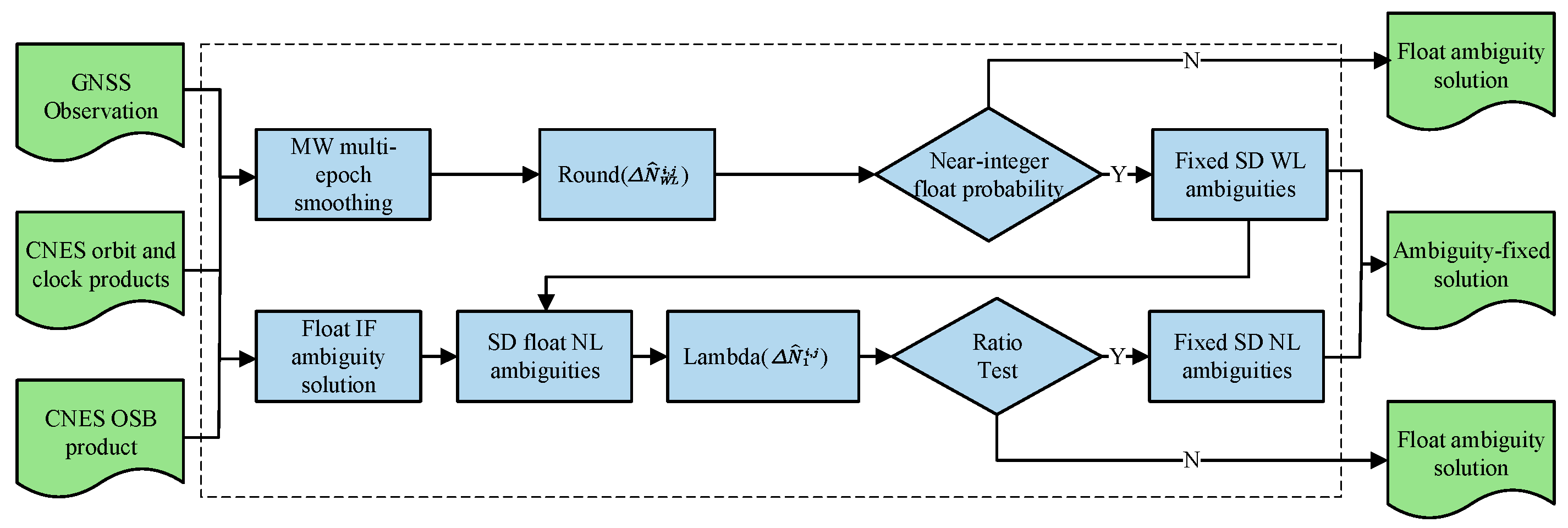
In this study, we utilize the post-processed OSB products provided by the Centre National d’Études Spatiales (CNES) analysis center (note that this differs from the traditional IRC-based fixing method). The IPPP fixing procedure presented herein is generalizable and can also be applied to clock and OSB products from other IGS analysis centers. The fundamental workflow for implementing OSB products alongside other post-processed precise products is illustrated in Figure 1.
To recover the integer nature of the ambiguities, a cascaded ambiguity resolution strategy is adopted, as proposed by Ge et al. [20]. In this approach, the ionosphere-free ambiguity is decomposed into wide-lane and narrow-lane components, and all three ambiguity terms are subsequently estimated. The relationship among these components is described by Equation (6).
Δ N ~ I F i , j = N ~ I F i N ~ I F j
The first step is to estimate the float ionosphere-free ambiguities, which forms the foundation for implementing IPPP. In this study, the satellite with the highest elevation angle is selected as the reference satellite. Between-satellite single differences (SDs) are then formed between the reference satellite and the remaining satellites involved in the ambiguity resolution. Using an extended Kalman filter (EKF), the float single-differenced ionosphere-free ambiguities are denoted as Δ N ~ I F i , j , where i refers to the satellite under consideration and j denotes the reference satellite.
The next step is to fix the wide-lane ambiguities. The float wide-lane ambiguities can be derived from the MW combination. The MW combined observation equation is given as follows:
Δ N ^ W L i , j = λ W L Δ N W L i , j + λ W L Δ u W L i , j + λ W L Δ O r , W L i , j + λ W L Δ ε W L i , j
Δ O r , W L i , j represents the phase center offset (PCO) correction. When the PCO corrections for the first and second frequencies are equal, Δ O r , W L i , j becomes zero. Δ u W L i , j denotes satellite and receiver hardware bias. After applying the OSB corrections and compensating for the vertical PCO error, the satellite-side hardware bias and PCO-related bias in the wide-lane ambiguity are effectively removed—this is referred to as the Wide-lane Satellite Bias (WSB). Subsequently, by forming between-satellite single differences, the receiver-side hardware biases—known as the Wide-lane Receiver Bias (WRB)—can also be eliminated, thereby restoring the integer nature of the wide-lane ambiguity.
Δ N ^ W L i , j = ( N ^ 1 i N ^ 2 i ) ( N ^ 1 j N ^ 2 j )
The MW combination has a relatively long wavelength (approximately 86 cm for GPS), and Equation (9) possesses inherent integer characteristics. After multi-epoch smoothing, the wide-lane ambiguities can be directly fixed by applying rounding.
Finally, the narrow-lane ambiguities are fixed. Due to the short wavelength of N ^ 1 i (approximately 19 cm for GPS), measurement noise and multipath effects can cause significant deviations between N ^ 1 and the true ambiguity N 1 . Moreover, the strong correlation among ambiguities associated with different satellites must be taken into account. Therefore, the LAMBDA method is employed to reliably fix N 1 . Once fixing N 1 , it is implemented as a virtual observation to constrain the Kalman filter state, yielding the ambiguity-fixed solution.

2.2. Fundamentals of Time and Frequency Transfer

The receiver clock offset d t r estimated in IPPP represents the time difference between the local receiver clock and the time scale t r e f of the precise satellite products. It is important to note that the receiver clock in this context refers specifically to the phase clock, as it is estimated solely from carrier-phase observations. This approach avoids contamination from the pseudorange-derived clock estimates during the ambiguity resolution process [10].
Since the time scale t r e f provided by the precise satellite products is consistent across stations, the local time difference between any two stations A and B can be derived by a simple differencing of their respective clock offsets. The resulting time difference between the two local receiver clocks is given by
Δ t = d t A d t B = ( t A t r e f ) ( t B t r e f )
where t A and t B are the local time at stations A and B, respectively, and t r e f is the time scale of the satellite products.

2.3. Day-Boundary Discontinuity Compensation

Currently, the majority of precise post-processed products provided by the IGS analysis center are generated in daily batches. On the one hand, satellite time scale discontinuities may occur at daily boundaries in the precise satellite products. On the other hand, during IPPP processing, strong correlations between parameters may cause the receiver clock estimates to be affected by hardware delays embedded in the ambiguity parameters—particularly wide-lane and narrow-lane delays—resulting in polluted clock solutions. Considering that these uncertainties may vary across time and location, their propagation into time and frequency transfer links between stations can lead to discontinuities at day boundaries.
According to Equation (5), a quantitative relationship between the receiver clock offset parameter and the narrow-lane (NL) ambiguity can be derived [21]. For example, a single cycle jump in the NL ambiguity (assuming GPS L1 and L2 frequencies of 1575.42 MHz and 1227.60 MHz, respectively, yielding an NL wavelength of approximately 0.19 m) would result in a corresponding jump in the clock offset of approximately 0.353 ns. Therefore, NL ambiguity cycles can be exploited to absorb clock discontinuities and repair the day-boundary discontinuities in the time link.
To minimize the impact of such day-boundary discontinuities, the correction can be performed either at the PPP solution level or during time link formation [21]. In this study, we propose a convenient and effective correction strategy at the link level to mitigate day-boundary jumps as much as possible. The proposed method consists of the following steps:
(I) Estimating the clock jump across the day boundary.
Since NL ambiguities may change between daily batches, such changes will inevitably introduce clock jumps equivalent to integer multiples of the NL wavelength. Based on this, standard processing using single-day products is first performed. After detecting a day-boundary discontinuity and verifying it over multiple epochs, the float-level clock jump can be estimated directly.
(II) Bridging the discontinuity in the time link.
Once the float jump in the clock offset has been determined, it is rounded to the nearest integer multiple of the NL cycle, based on the known conversion factor. Since we are dealing with between-satellite single-difference ambiguities, the compensation can be implemented in one of two ways: either by keeping the ambiguity of the reference satellite fixed and adjusting the ambiguity of the other satellite, or by fixing the ambiguity of the secondary satellite and applying the correction to the reference satellite. This procedure effectively bridges the cycle-induced clock jump and restores the continuity of the time link across the day boundary.

2.4. Robust Sliding-Window Weighted Strategy

During single-epoch integer ambiguity fixing, degraded signal quality, excessive multipath effects, or imperfections in post-processed precise products may introduce anomalies into the observations. These deviations are often absorbed by the fractional part of the float ambiguity estimates. When the fractional residual approaches 0.5 cycles, it may result in incorrect ambiguity fixes to a neighboring integer value. Due to the strong correlation between ambiguities and receiver clock parameters, such erroneous integer constraints can directly compromise the receiver clock estimation, potentially leading to instability in the time and frequency transfer link—manifesting as abrupt jumps or isolated outliers.
In conventional residual analysis for ambiguity fixing, the float residuals of narrow-lane ambiguities serve as an indicator of fixing quality. A commonly adopted threshold is 0.25 cycles, below which the fixed solution is considered reliable. However, under abnormal conditions, relying solely on single-epoch residuals may not provide sufficient sensitivity for detecting outliers.
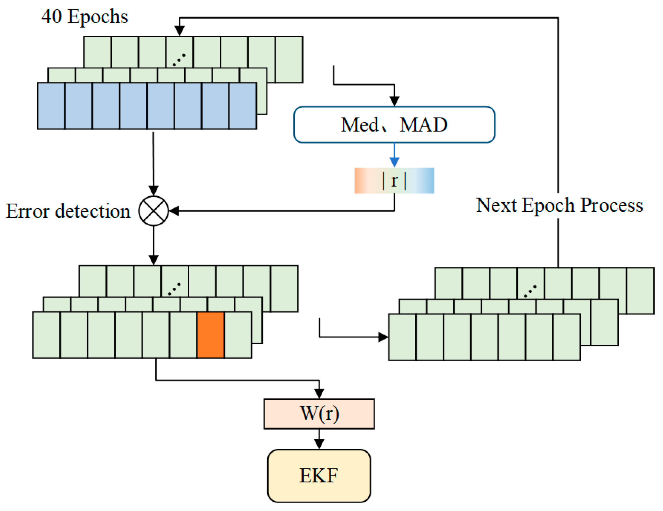
To address this issue, we propose a robust ambiguity fixing constraint method that incorporates multi-epoch narrow-lane residual information, as shown in Figure 2. The key steps are as follows:
(I) Construction of Detection Metric
To enhance sensitivity to local anomalies, we employ a sliding window to statistically evaluate the float residuals of narrow-lane ambiguities across multiple consecutive epochs for all satellites involved in the ambiguity resolution process. The selection of an appropriate sliding window size must strike a balance between estimation accuracy and sensitivity to errors [22], as well as between real-time responsiveness and the use of historical information. In the case of sudden ambiguity fixing errors, a small window is more responsive to transient anomalies and can effectively capture such events [23,24]. However, an overly small window may result in misidentification of normal residuals as outliers. Previous studies have shown that one hour of epoch data provides a sufficient number of points for anomaly detection [21]. In this study, the primary motivation for using a small window is to preserve finer details, which is particularly suitable for detecting abrupt changes while maintaining low latency and enabling timely identification of ambiguity fixing errors. Based on extensive experimental evaluations of different window lengths, a 40-epoch window was selected by considering both positioning accuracy and computational efficiency. From the residual set, the median and median absolute deviation (MAD) are computed to construct a robust error detection metric. Compared with the standard deviation, the MAD provides better resistance to outliers and is thus more suitable for robust detection in noisy datasets.
| r | = | r e s m e d | M A D
where res denotes the fractional part of the float narrow-lane ambiguity; med represents the median of the residual dataset; MAD is the median absolute deviation of the parameter dataset; and r is the test statistic used for error detection.
(II) Error Detection
An error detection procedure is applied to the set of narrow-lane ambiguity residuals. A dynamic threshold is used for the test, defined as k = 1.345 × MAD, which corresponds to 95% Gaussian efficiency. If an outlier is detected, it will be down-weighted in the subsequent step, and the residual from the current epoch will be removed from the sliding window used to maintain the residual set. Otherwise, the PPP processing proceeds to the next epoch as usual.
(III) Adaptive Down-Weighting
For satellites identified with abnormal narrow-lane ambiguity behavior, a Huber-based down-weighting strategy is employed. The Huber function is used to compute the weight factor of each affected satellite, which is then applied to adjust the observation weight accordingly. This procedure reduces the influence of incorrect ambiguities on the estimation of receiver clock offset and ensures robust PPP ambiguity resolution.
w ( r ) = 1 , | r | k k r α , | r | > k
Here, w ( r ) denotes the weighting factor constructed based on the error detection metric, k is the dynamic threshold, and α represents the variance inflation factor.
3. Data and Strategy

3.1. Dataset

To validate the effectiveness of the proposed method and evaluate the performance of IPPP time and frequency transfer, we collected 30 days of multi-frequency GNSS observations at a 30-s interval from six globally distributed IGS reference stations, covering day of year (DOY) 72–101, 2025 (corresponding to MJD 60746–60776). The corresponding post-processed precise products, including satellite orbits, clock offsets, and OSB corrections, were obtained from the CNES analysis center. All stations are equipped with high-performance atomic clocks. The geographical distribution of the stations is illustrated in Figure 3, and the hardware configuration of each station is summarized in Table 1. The baseline distances for the selected time links are listed in Table 2.
For the zero-baseline experiment, two co-located stations in the United States, USN7 and USN8, were selected as the test sites. For the medium- and long-baseline experiments, IENG was chosen as the central reference station, forming three time and frequency transfer links. The IGS final precise products were used as the reference. Additionally, two domestic Polish stations, BOR1 and GUM5, were selected. Although the two stations collect only GPS observations, an optical fiber time transfer link is available between them. Owing to its superior frequency stability compared to GNSS time links and the absence of day-boundary discontinuities [9], this optical link can serve as a benchmark for independently validating the performance of IPPP time and frequency transfer.

3.2. Processing Strategies

The dual-frequency ionosphere-free combination is formed based on GPS L1C and L2W observations, and all parameters are solved using single-epoch processing. IPPP employs a stepwise ambiguity fixing strategy, in which the wide-lane (WL) satellite-differenced ambiguities are sequentially rounded to integers and fixed. Once fixed, these ambiguities are used to generate virtual observations to constrain the PPP equations. Subsequently, the narrow-lane (NL) satellite-differenced ambiguities are fixed using the LAMBDA method and validated by the ratio test. The reference satellite is selected as the one with the highest elevation angle. A partial ambiguity resolution (PAR) strategy is applied by selecting ambiguities in descending order of satellite elevation. Upon successful NL ambiguity fixing, the receiver clock offset is estimated under the combined constraints of WL and NL ambiguities. Notably, to further reduce the probability of incorrect ambiguity fixes, a more rigorous fixing strategy is adopted: after obtaining a continuous and stable PPP solution, the Kalman filter states are updated only when the ambiguities are fixed correctly for eight consecutive epochs [1,25]. In all processing schemes, all datasets are processed in static mode, antenna phase center offsets and variations are corrected using ATX files, the receiver clock offset is modeled as white noise, and the receiver coordinates are estimated as constants. Further details on the error handling and modeling strategies can be found in Table 3.

4. Results and Analysis

In this section, the availability of the IPPP algorithm based on OSB products is first validated. Subsequently, the results of the day-boundary discontinuity repair experiments and related simulations are presented. Finally, a comprehensive performance evaluation of the proposed IPPP time and frequency transfer scheme is conducted using multiple transfer links across various baselines. In the tests, the performance of GPS IPPP is compared with the GPS PPP float solution (to avoid contamination of phase clocks by pseudorange-related biases, carrier phase-only processing was employed in both the IPPP and PPP experimental schemes), optical fiber links, and the IGS final products employing the modified Allan deviation (MDEV) as the primary stability metric. Notably, to ensure consistency with the IGS final products, the experimental results were resampled to obtain a uniform interval of 300 s. Observations from all selected stations span from MJD 60,746 to 60,776.

4.1. Distribution of the WL and NL Ambiguity Fractional-Cycle Residuals

It is generally accepted that the NL residuals represent the quality of ambiguity fixing, and effective integer ambiguity resolution can only be achieved when these residuals are sufficiently small. In both WL and NL ambiguity resolution, the subset of satellites used for ambiguity fixing is initially selected based on residuals, with a threshold set at 0.25 cycles. Figure 4 and Figure 5 illustrate the probability distribution of float WL and NL ambiguity residuals during the 30-day short baseline link (SPT0-IENG) experiment, showing a large concentration of residuals near zero to ensure reliable ambiguity resolution. Table 4 summarizes the ratios of WL and NL fractional residuals within 0.25 cycles. The statistical average was computed based on the measurements from both stations. Specifically, 97.90% of WL fractional residuals are within 0.25 cycles, and 87.84% are within 0.15 cycles; for NL fractional residuals, 99.70% fall within 0.25 cycles, and 97.83% within 0.10 cycles. Moreover, the standard deviations of both WL and NL residuals are within picosecond-level precision, indicating good accuracy. These results demonstrate that the OSB products from the CNES satisfy the requirements for IPPP and enable precise time and frequency transfer.

4.2. Repair of Day-Boundary Discontinuities

In this section, GPS observation data from the SPT0-IENG link between day of year (DOY) 72 and 78 in 2025 were collected to conduct continuity tests of IPPP time and frequency transfer. The experiments are divided into two groups: before and after discontinuity repair. Note that a small vertical offset is applied to the time transfer results in the figure to facilitate better comparison. As shown by the blue curve in Figure 6, when performing standard single-day batch processing for time and frequency transfer, a discontinuous clock jump occurs at the day boundary (between DOY 74–75, 75–76 and 76–77) with a magnitude of approximately 0.353 ns. Using the compensation algorithm proposed in this study, the clock jump at the day boundary is actively absorbed by the satellite-differenced NL ambiguities, thereby repairing the discontinuity. The orange curve in the figure indicates that after applying the NL ambiguity-based clock jump absorption, the discontinuities in the time link between DOY 74–75, 75–76 and 76–77 have been bridged, and the discontinuities are minimized.

4.3. Measured-Data and Simulation Time Link Experiments

4.3.1. IPPP Time Links of GPS, BDS, and GAL

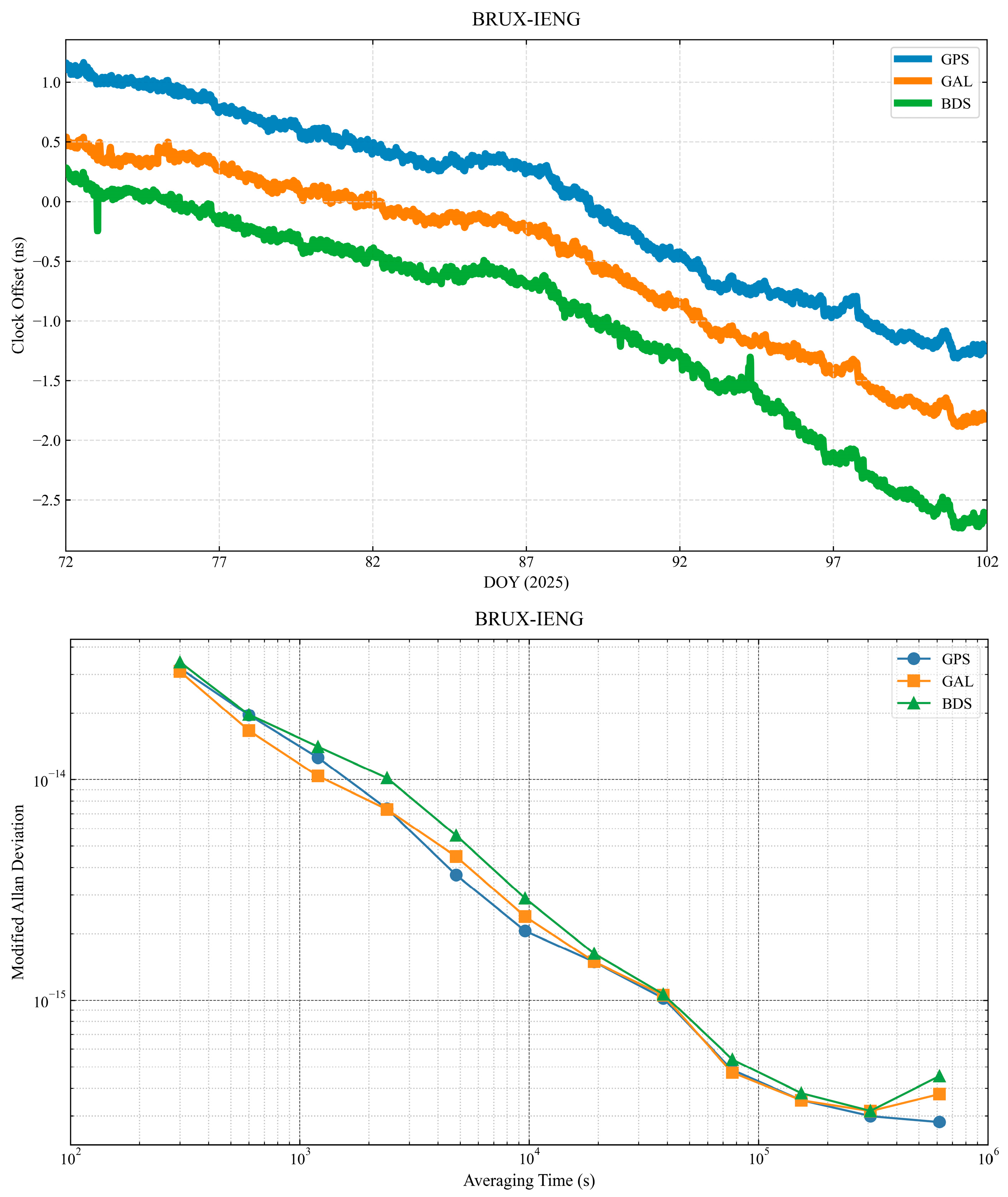
To evaluate the general applicability of the proposed algorithm, IPPP time transfer experiments were conducted using GPS, Galileo (GAL), and BeiDou (BDS) signals. For this purpose, 30-day time transfer links were established between the BRUX and IENG stations using GPS L1C and L2W signals, GAL L1C and L5Q signals, and BDS B1C and B2a signals, respectively. The goal was to assess the frequency stability performance across different GNSS constellations.
As shown in Figure 7, continuous time transfer was successfully achieved using IPPP for all three systems—GPS, GAL, and BDS. Among them, BDS exhibited slightly inferior frequency stability compared to GPS and GAL. Table 5 and Table 6 present the standard deviation (STD) and the frequency stability of the time link. In terms of the STD of the time link, GPS IPPP achieved 0.744 ns, GAL IPPP 0.727 ns, and BDS IPPP 0.859 ns. At an averaging time of 1200 s, the frequency stability reached 1.258 × 10⁻¹⁴ for GPS, 1.038 × 10⁻¹⁴ for GAL, and 1.411 × 10⁻¹⁴ for BDS. When the averaging time increased to 9600 s, the corresponding values were 2.061 × 10⁻¹⁵, 2.394 × 10⁻¹⁵, and 2.893 × 10⁻¹⁵. At 76,800 s, the stability further improved to 4.838 × 10⁻¹⁶ (GPS), 4.707 × 10⁻¹⁶ (GAL), and 5.403 × 10⁻¹⁶ (BDS). Compared with GPS and GAL, the frequency transfer stability of BDS time links demonstrates relatively inferior performance. Possible contributing factors include the relatively lower performance of onboard clocks; the limited number of visible satellites when using the newly introduced BDS-3 signals (B1C/B2a) alone; lower global availability of BDS ground stations, which may lead to inconsistencies in orbit and clock product precision; and higher pseudorange multipath noise levels.

4.3.2. Simulation of Incorrect Ambiguity Fixes

To compare the performance of the IGIII and the proposed robust sliding-window weighting strategies under worst-case conditions, a simulated experiment involving incorrect ambiguity fixes was conducted over the 7-day time link between SPT0 and IENG (DOY 72–78). Specifically, incorrect ambiguity fixes at epochs 3000, 4000, and 5000 were introduced at station SPT0. As shown in Figure 8, such incorrect ambiguity fixes cause significant fluctuations in the time transfer link between BRUX and SPT0, with the carrier-phase residual increasing sharply to 9.6 cm, ultimately leading to a degradation in time and frequency stability.
As shown in Figure 9 and Figure 10, the IGIII triple-segment down-weighting strategy (parameter 1 is 0.25 cycles and parameter 2 is 0.15 cycles) [11,26] fails to fully eliminate the anomalies caused by incorrect ambiguity resolution. Table 7 presents the STD of carrier-phase residuals under different strategies. Both the time transfer link and the carrier-phase residuals exhibit abnormal fluctuations, with the STD of the residuals increasing to 6.7 cm. In contrast, the proposed robust sliding-window weighting strategy, which employs dynamic thresholding, effectively reduces the impact of incorrect ambiguity fixes by suppressing abrupt changes in the time transfer link. As a result, the STD of the carrier-phase residuals is reduced to 5.2 cm. These findings indicate that the dynamic thresholds derived from the robust sliding-window weighting algorithm can more comprehensively and accurately detect incorrect ambiguity fixes, thereby improving the reliability and stability of time transfer links.

4.4. Zero-Baseline Experiment

In a zero-baseline configuration, the signal propagation paths from the satellites to the two stations are nearly identical, thereby minimizing geometry-related errors. Additionally, the use of a shared high-performance external clock significantly reduces the impact of receiver-related noise. For these reasons, zero-baseline setups are frequently employed to assess the noise level and performance of time and frequency transfer techniques. In this study, USN7 and USN8—equipped with identical high-stability hydrogen masers and sharing a common antenna—were selected to validate the time transfer performance under a common-clock, zero-baseline condition. Results were also compared against the IGS final products.
Figure 11 presents the zero-baseline time transfer results between USN7 and USN8, using both PPP float solutions and IPPP with ambiguity resolution. The float solution was obtained from a standard processing procedure, while the IPPP solution was derived by constraining the float solution with resolved integer ambiguities. As expected, due to the shared antenna and high-quality external clock, the time transfer results exhibit minimal fluctuations. For visualization purposes, the curves were shifted to align the baseline levels. Compared to the PPP float solution, the IPPP results show a noticeable improvement in smoothness and stability. Furthermore, as shown in red circles, the time transfer link between the USN7 and USN8 stations exhibits significant fluctuations when ambiguities are incorrectly fixed, resulting in a noticeable degradation of frequency stability. Traditional triple-segment down-weighting schemes, such as the IGIII method (parameter 1 is 0.25 cycles and parameter 2 is 0.15 cycles) [11,26], are not fully effective in suppressing these anomalies. In contrast, the proposed sliding window-based robust weighting strategy dynamically adjusts the weights and helps recover correct ambiguity fixing. This adaptive mechanism successfully mitigates the outliers in the time transfer link, resulting in fewer isolated points and enhanced robustness against abnormal data.
The STD of the clock differences over a 30-day period was calculated. The GPS IPPP Robust, GPS IPPP IGIII, and GPS PPP solutions yielded STDs of approximately 9 ps, 10 ps, and 29 ps, respectively, all indicating high time transfer precision. In terms of frequency stability analysis, GPS IPPP exhibits increasingly improved stability over longer averaging intervals, as shown in Table 8. For zero-baseline time transfer using GPS IPPP Robust, frequency stabilities at averaging times of 1200 s, 9600 s, and 38,400 s are denoted as 3.699 × 10⁻¹⁵, 5.235 × 10⁻¹⁶, and 1.087 × 10⁻¹⁶, respectively—representing improvements of 15.1%, 59.8%, and 82.0% over the corresponding float PPP solutions. When the averaging time extended to 76,800 s, the frequency stability of GPS IPPP Robust reached 3.332 × 10⁻¹⁷. The reliability of the proposed robust sliding-window weighting strategy was thus confirmed, and it was subsequently adopted as a default component in all IPPP experimental schemes involving baselines of different lengths. For simplicity of notation, all GPS IPPP experimental schemes are assumed to incorporate both the day-boundary discontinuity repair algorithm and the robust sliding-window weighted strategy by default.

4.5. Additional Baseline Experiments

4.5.1. Optical Fiber Link Experiment

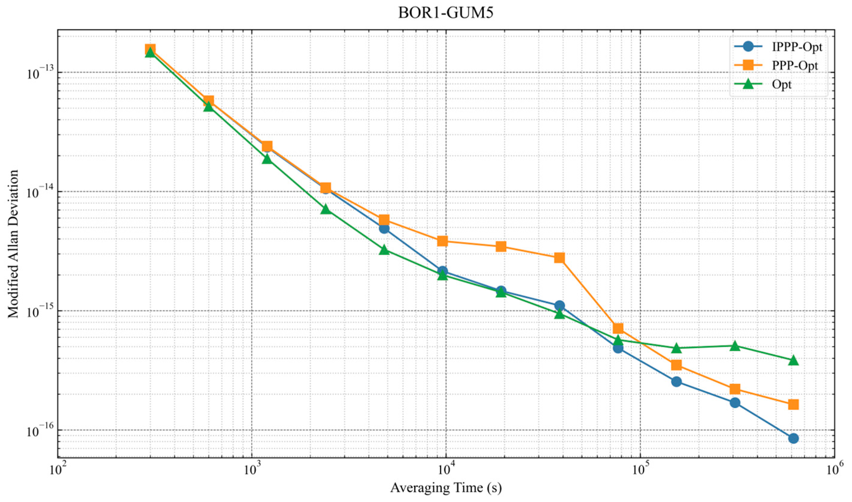
To benchmark IPPP time transfer performance, a comparative analysis was conducted against a high-precision optical fiber link between BOR1 and GUM5.
As shown in Figure 12, the performance of the optical fiber link surpasses that of the GPS IPPP and PPP differential schemes for averaging times shorter than 9600 s. This is primarily because the transmission medium in optical fiber links is more stable—largely due to consistent refractive index and signal power loss characteristics. These results also indicate that the IPPP- and PPP-based time transfer links are subject to higher short-term frequency noise.
For longer averaging times, however, the IPPP differential scheme outperforms the optical fiber link in terms of time transfer precision, which may be attributed to clock instability or other limiting factors on the optical fiber link.

4.5.2. Short-Baseline and Long-Baseline Experiment

Using IENG as the reference station, two short-baseline links (BRUX-IENG and SPT0-IENG) and one long-baseline link (TWTF–IENG) were tested. To evaluate the performance of the IPPP-based time transfer solution over different baseline lengths, the results were compared with time links derived from the IGS final products.
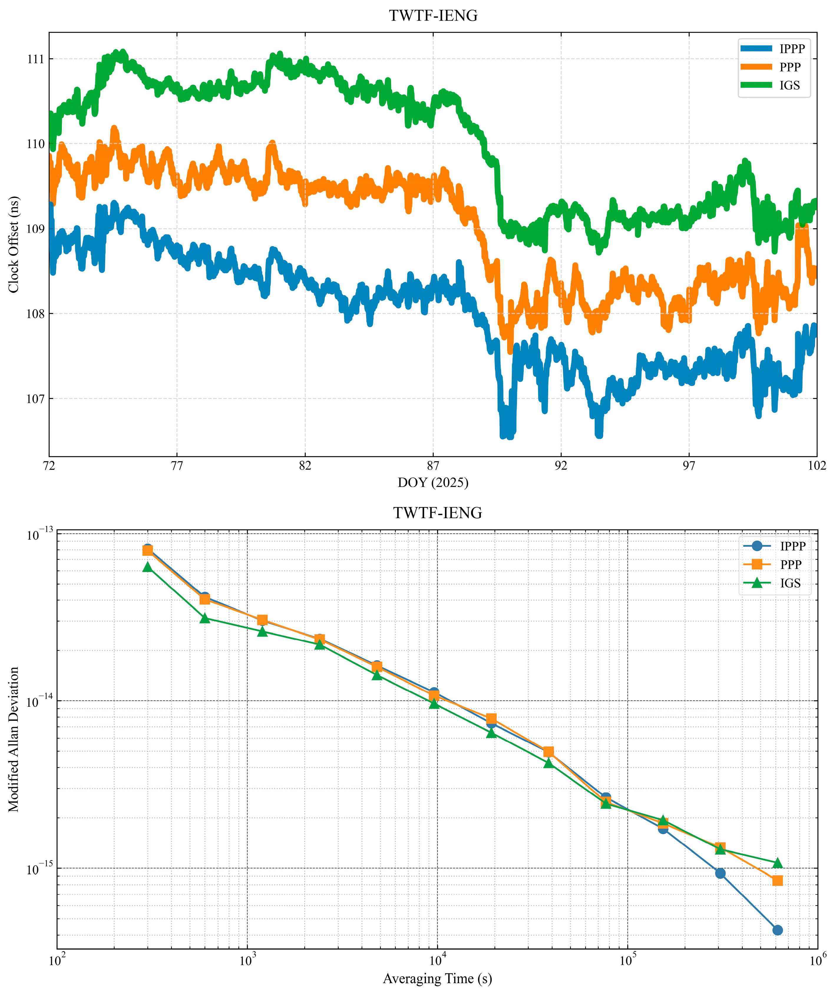
Figure 13 and Figure 14 present the comparisons and MDEV analyses of the GPS IPPP, GPS PPP, and IGS final product time links for the tested baselines. It is evident from the time series comparison that the IGS-derived links exhibit day-boundary discontinuities, which is consistent with the fact that they are based on single-day batch processing. In contrast, the GPS IPPP and PPP links—enhanced with a compensation algorithm—show significantly reduced discontinuities at the day boundaries.
Table 9, Table 10 and Table 11 present the frequency stability of the three solutions. When the averaging time is relatively short, the frequency stability of the three solutions remains comparable. This is expected, as the IPPP solution is derived by applying integer ambiguity constraints to the PPP float solution, and thus inherits its short-term stability characteristics [13]. Interestingly, for long baselines, the IGS solution sometimes exhibits slightly better stability, likely due to the fact that the path-consistent errors are not effectively mitigated by differencing over long distances. At an averaging time of 76,800 s, all three schemes exhibit similar levels of frequency stability. As the averaging time exceeds 153,600 s for all tested links, both GPS IPPP and PPP demonstrate improved frequency stability compared to the IGS final products, with IPPP consistently delivering the best performance. In the comparison with IGS final products over both short- and long-baseline links, for the averaging time of 307,200 s, the GPS IPPP solution achieves an average improvement of approximately 29.3% in frequency stability over the PPP float solution, and about 32.6% over the IGS final product.

5. Conclusions

The IPPP technique enhances the accuracy of time and frequency transfer by restoring the integer nature of carrier-phase ambiguities, particularly improving long-term frequency stability. In this study, integer ambiguity resolution was performed using OSB products. Additionally, a day-boundary discontinuity correction algorithm and a robust sliding-window weighting strategy were proposed and employed to assess the effectiveness of IPPP in time and frequency comparison. The following conclusions can be drawn from the analysis:
(1) The proposed day-boundary correction method effectively mitigates clock jumps at daily boundaries. The robust sliding-window weighting approach fully utilizes the narrow-lane residuals across multiple adjacent epochs, enabling more reliable detection and suppression of erroneous ambiguity fixes.
(2) Over a 7-day dataset, the IPPP time transfer technique achieved frequency stabilities of 4.838 × 10⁻¹⁶ (GPS), 4.707 × 10⁻¹⁶ (Galileo), and 5.403 × 10⁻¹⁶ (BDS) at an averaging time of 76,800 s. In the simulation experiments, the proposed robust sliding-window weighting algorithm demonstrated its ability to derive adaptive thresholds, enabling more comprehensive detection of anomalies compared to the IGIII method. Specifically, when applying the IGIII scheme, the carrier-phase residual reached 6.7 cm, whereas with the robust sliding-window approach, the residual was reduced to 5.2 cm.
(3) Across both zero-baseline and longer baseline links, the IPPP time transfer technique consistently outperformed the traditional float PPP solution in terms of accuracy and stability—especially for long-term averaging. Especially in differential comparisons with optical fiber time transfer, the IPPP solution showed better long-term stability than the optical fiber link itself. In the zero-baseline experiment, the frequency stability of GPS IPPP showed improvements of 15.1%, 59.8%, and 82.0% over the float PPP solution at averaging times of 1200 s, 9600 s, and 38,400 s, respectively. At 76,800 s, GPS IPPP achieved a frequency stability of 3.332 × 10⁻¹⁷. For both short- and long-baseline links, when compared to the IGS final products at an averaging time of 307,200 s, the IPPP solution showed an average improvement of approximately 29.3% over the PPP float solution and 32.6% over the IGS products.
Since this study is based on dual-frequency ionosphere-free combinations, it inherently requires that the user equipment support at least two frequencies. In the future, we aim to extend this work to single-frequency and multi-GNSS scenarios and further investigate ionospheric error correction, with the goal of enabling more flexible and reliable time transfer under constrained environments.

Author Contributions

Conceptualization, methodology, and validation: K.W. and W.Q.; data supply: W.W.; discussion—D.L., P.W. and X.Y. All authors have read and agreed to the published version of the manuscript.

Funding

Youth Innovation Promotion Association of the Chinese Academy of Science (Grant No. Y2023108), CAS “Light of West China—Western Interdisciplinary Team” Program [xbzg-zdsys-202308], the National Natural Science Foundation of China (Grant No. 12273047).

Data Availability Statement

The original contributions presented in this study are included in the article. Further inquiries can be directed to the author at wukun@ntsc.ac.cn.

Conflicts of Interest

The authors declare no conflict of interest.

References

  1. Collins, P.; Bisnath, S.; Lahaye, F.; Héroux, P. Undifferenced GPS Ambiguity Resolution Using the Decoupled Clock Model and Ambiguity Datum Fixing. Navigation 2010, 57, 123–135. [Google Scholar] [CrossRef]
  2. Laurichesse, D.; Mercier, F.; Berthias, J.-P.; Broca, P.; Cerri, L. Integer Ambiguity Resolution on Undifferenced GPS Phase Measurements and Its Application to PPP and Satellite Precise Orbit Determination. Navigation 2009, 56, 135–149. [Google Scholar] [CrossRef]
  3. Geng, J.; Meng, X.; Dodson, A.H.; Teferle, F.N. Integer Ambiguity Resolution in Precise Point Positioning: Method Comparison. J. Geod. 2010, 84, 569–581. [Google Scholar] [CrossRef]
  4. Petit, G.; Leute, J.; Loyer, S.; Perosanz, F. Sub 10−16 Frequency Transfer with IPPP: Recent Results. In Proceedings of the 2017 Joint Conference of the European Frequency and Time Forum and IEEE International Frequency Control Symposium (EFTF/IFCS), Besançon, France, 9–13 July 2017; IEEE: New York, NY, USA, 2017; pp. 784–787. [Google Scholar]
  5. Fujieda, M.; Yang, S.H.; Gotoh, T.; Hwang, S.W.; Hachisu, H.; Kim, H.; Lee, Y.K.; Tabuchi, R.; Ido, T.; Lee, W.K. Advanced Satellite-Based Frequency Transfer at the 10−16 Level. IEEE Trans. Ultrason. Ferroelectr. Freq. Control 2018, 65, 973–978. [Google Scholar] [CrossRef]
  6. Loyer, S.; Perosanz, F.; Mercier, F.; Capdeville, H.; Marty, J.-C. Zero-Difference GPS Ambiguity Resolution at CNES–CLS IGS Analysis Center. J. Geod. 2012, 86, 991–1003. [Google Scholar] [CrossRef]
  7. Yao, J.; Levine, J. A New Algorithm to Eliminate GPS Carrier-Phase Time Transfer Boundary Discontinuity. In Proceedings of the 45th Annual Precise Time and Time Interval Systems and Applications Meeting, Bellevue, WA, USA, 2–5 December 2013; Institute of Navigation: Manassas, VA, USA, 2013. [Google Scholar]
  8. Dach, R.; Schildknecht, T.; Hugentobler, U.; Bernier, L.G.; Dudle, G. Continuous Geodetic Time-Transfer Analysis Methods; IEEE Transactions on Ultrasonics Ferroelectrics & Frequency Control: Piscataway, NJ, USA, 2006. [Google Scholar]
  9. Guo, J.; Defraigne, P.; Pinat, E. Continuous Time and Frequency Transfer Achieved by Multi-Day GPS/Galileo/BDS Integer Precise Point Positioning. GPS Solut. 2025, 29, 95. [Google Scholar] [CrossRef]
  10. Gerard, P. Sub-10-16 Accuracy GNSS Frequency Transfer with IPPP. GPS Solut. 2021, 25, 22. [Google Scholar]
  11. Ren, Z.; Lyu, D.; Gong, H.; Peng, J.; Huang, X.; Sun, G. Continuous Time and Frequency Transfer Using Robust GPS PPP Integer Ambiguity Resolution Method. GPS Solut. 2023, 27, 82. [Google Scholar] [CrossRef]
  12. Li, X.; Liang, D.; Li, X.; Huang, J.; Wu, J.; Gou, H. Quality Monitoring of Real-Time PPP Service Using Isolation Forest-Based Residual Anomaly Detection. GPS Solut. 2024, 28, 118. [Google Scholar] [CrossRef]
  13. Xu, W.; Shen, W.; Cai, C.; Li, L.; Wang, L.; Ning, A.; Shen, Z. Comparison and Evaluation of Carrier Phase PPP and Single Difference Time Transfer with Multi-GNSS Ambiguity Resolution. GPS Solut. 2022, 26, 58. [Google Scholar] [CrossRef]
  14. Yang, Y.; Song, L.; Xu, T. Robust Estimator for Correlated Observations Based on Bifactor Equivalent Weights. J. Geod. 2002, 76, 353–358. [Google Scholar] [CrossRef]
  15. Teunissen, P.J.G.; Verhagen, S. The GNSS Ambiguity Ratio-Test Revisited: A Better Way of Using It. Surv. Rev. 2009, 41, 138–151. [Google Scholar] [CrossRef]
  16. Guo, J.; Geng, J. Integer Ambiguity Validation through Machine Learning for Precise Point Positioning. Satell. Navig. 2025, 6, 14. [Google Scholar] [CrossRef]
  17. Chen, C.; Xiao, G.; Chang, G.; Xu, T.; Yang, L. Assessment of GPS/Galileo/BDS Precise Point Positioning with Ambiguity Resolution Using Products from Different Analysis Centers. Remote Sens. 2021, 13, 3266. [Google Scholar] [CrossRef]
  18. Geng, J.; Yang, S.; Guo, J. Assessing IGS GPS/Galileo/BDS-2/BDS-3 Phase Bias Products with PRIDE PPP-AR. Satell. Navig. 2021, 2, 17. [Google Scholar] [CrossRef]
  19. Cao, X.; Yu, X.; Ge, Y.; Liu, T.; Shen, F. BDS-3/GNSS Multi-Frequency Precise Point Positioning Ambiguity Resolution Using Observable-Specific Signal Bias. Measurement 2022, 195, 111134. [Google Scholar] [CrossRef]
  20. Geng, J.; Bock, Y. Triple-Frequency GPS Precise Point Positioning with Rapid Ambiguity Resolution. J. Geod. 2013, 87, 449–460. [Google Scholar] [CrossRef]
  21. Petit, G.; Kanj, A.; Loyer, S.; Delporte, J.; Mercier, F.; Perosanz, F. 1 × 10⁻¹⁶frequency Transfer by GPS PPP with Integer Ambiguity Resolution. Metrologia 2015, 2, 301. [Google Scholar] [CrossRef]
  22. Song, W.; Zhang, R.; Yao, Y.; Liu, Y.; Hu, Y. PPP Sliding Window Algorithm and Its Application in Deformation Monitoring. Sci. Rep. 2016, 6, 26497. [Google Scholar] [CrossRef]
  23. Zheng, X.; Dong, Y.; Zhao, Y.; Zhang, B.; Li, M. TSF-GINS: Based on Time-Fixed Sliding Window with Factor Graph a Global Navigation Satellite System and Inertial Measurement Unit Tightly Coupled Localization System. Measurement 2025, 239, 115421. [Google Scholar] [CrossRef]
  24. Ge, Y.; Zhou, F.; Liu, T.; Qin, W.; Wang, S.; Yang, X. Enhancing Real-Time Precise Point Positioning Time and Frequency Transfer with Receiver Clock Modeling. GPS Solut. 2019, 23, 20. [Google Scholar] [CrossRef]
  25. Zhang, X.; Li, P.; Guo, F. Ambiguity Resolution in Precise Point Positioning with Hourly Data for Global Single Receiver. Adv. Space Res. 2013, 51, 153–161. [Google Scholar] [CrossRef]
  26. Yang, Y. Robust estimation for dependent observation. Manuscripta Geod. 1994, 19, 10–17. [Google Scholar]
Figure 1. Flowchart of the ambiguity resolution strategy based on CNES OSB products using a dual-frequency ionosphere-free combination. Green boxes denote data or products while blue boxes denote processes.
Remotesensing 17 02878 g001
Figure 2. Structure of the robust sliding-window weighting algorithm. The blue blocks represent the narrow-lane residuals currently being processed; the green blocks indicate residuals classified as normal, while the orange blocks denote residuals identified as outliers.
Remotesensing 17 02878 g002
Figure 3. Spatial distribution of the experimental stations. IENG (red dot) serves as the center, linked with the other stations (blue dots) to establish time links. An optical fiber link is used between BOR1 and GUM5.
Remotesensing 17 02878 g003
Figure 4. Statistics of WL and NL fractional residuals over 30 days (SPT0).
Remotesensing 17 02878 g004
Figure 5. Statistics of WL and NL fractional residuals over 30 days (IENG).
Remotesensing 17 02878 g005
Figure 6. Comparison of day-boundary discontinuity repair for the SPT0–IENG (about 1457 km) link over 7 days. The blue curve shows the time link before repair, and the orange curve shows the result after repair.
Remotesensing 17 02878 g006
Figure 7. Time transfer results and MDEV frequency stability comparison of GPS, Galileo, and BDS IPPP solutions over the BRUX-IENG (about 688km) link (DOY 72–101).
Remotesensing 17 02878 g007
Figure 8. Time transfer link comparison and carrier-phase residuals for the SPT0–IENG baseline (about 1457 km) after simulating incorrect ambiguity fixes at station SPT0 (DOY 72–78). An arbitrary vertical offset was added to the time link results for visual comparison. In the right figure, each color corresponds to a different satellite.
Remotesensing 17 02878 g008
Figure 9. Time transfer link comparison at station SPT0 after applying the IGIII scheme and the robust sliding-window weighting strategy (DOY 72–78).
Remotesensing 17 02878 g009
Figure 10. Carrier-phase residuals at SPT0 after processing with the IGIII scheme and the proposed robust sliding-window weighting algorithm. Each color corresponds to a different satellite.
Remotesensing 17 02878 g010
Figure 11. Frequency stability analysis of IPPP IGIII, IPPP Robust, and IPPP time transfer on USN7-USN8 zero-baseline common-clock link (DOY 72–101). Outliers in the time transfer link are marked by red circles in the upper panel of the figure.
Remotesensing 17 02878 g011
Figure 12. MDEV of time transfer links obtained by differencing the GPS IPPP, GPS PPP, and optical fiber link solutions and the corresponding optical fiber link (about 267 km).
Remotesensing 17 02878 g012
Figure 13. Time transfer links over short baselines (BRUX–IENG, about 688 km, and SPT0–IENG, about 1457 km) from DOY 72–101 are shown in the upper panel, with the corresponding MDEV stability analysis presented in the lower panel. The blue line represents the GPS IPPP solution, the orange line denotes the GPS PPP float solution, and the green line indicates the solution based on IGS final products. The time differences in the top panel remove a linear drift and add an arbitrary offset.
Remotesensing 17 02878 g013
Figure 14. Time transfer links over long baselines (TWTF–IENG) from DOY 72–101 are shown in the upper panel, with the corresponding MDEV stability analysis presented in the lower panel. The blue line represents the GPS IPPP solution, the orange line denotes the GPS PPP float solution, and the green line indicates the solution based on IGS final products. The time differences in the top panel remove a linear drift and add an arbitrary offset.
Remotesensing 17 02878 g014
Table 1. The hardware details of the stations.
StationReceiver TypeAntenna TypeAtomic Clock Type
IENGSEPT POLARX5TR-5.4.0SEPCHOKE_MC-NONEEXTERNAL H-MASER
BRUXSEPT POLARX5TR-5.5.0JAVRINGANT_DM-SCISEXTERNAL IMASER 3000
SPT0SEPT POLARX5TR-5.5.0TRM59800.00-OSODEXTERNAL H-MASER
TWTFSEPT POLARX4TR-2.9.6SEPCHOKE_B3E6-SPKEEXTERNAL H-MASER
BOR1TRIMBLE NETR9-5.45TRM59800.00-NONEEXTERNAL H-MASER
GUM5TTS-5NAX3G + C NONEEXTERNAL H-MASER
Table 2. The distance of the time links.
LinkTypeDistance
BRUX-IENGShort-baseline link688 km
SPT0-IENGShort-baseline link1457 km
TWTF-IENGLong-baseline link9736 km
USN7-USN8Zero-baseline link0 km
BOR1-GUM5Optical fiber link267 km
Table 3. Details of the PPP processing strategies.
ItemStrategy
Observations1 day pseudorange and carrier phase
Sampling rate of solutions30s
Elevation cut off
PCV and PCOigs20_2350.atx
Tropospheric delayDry delay: Corrected by Saastamoinen model;
Wet delay: Estimated as random walk
Ionospheric delayDual-frequency ionosphere-free combination correction
Relative effectApplied
Phase-windup effectCorrected
PositionsEstimated as daily constants
Receiver clockEstimated as white noise
Tidal effectsOcean tide file
EstimatorEKF
Table 4. Percentages of WL and NL fractional residuals within 30 days (%).
StationWL (Within 0.25)WL (Within 0.15)NL (Within 0.25)NL (Within 0.10)
SPT097.5485.2599.6197.68
IENG98.2690.4399.7997.97
Table 5. STD of GPS, GAL, and BDS IPPP time transfer links.
SystemGPSGALBDS
STD/ns0.744 0.7270.859
Table 6. Frequency stability of the BRUX-IENG test time links from DOY 72 to 101.
Averaging Time/sSolution
GPS GALBDS
12001.258 × 10−141.038 × 10−141.411 × 10⁻¹⁴
96002.061 × 10−152.394 × 10−152.893 × 10⁻¹⁵
768004.838 × 10−164.707 × 10−165.403 × 10⁻¹⁶
Table 7. STD of carrier-phase residuals under different strategies.
StrategyStimulateIGIIIRobust
STD/cm9.6 6.75.2
Table 8. Frequency stability of the USN7-USN8 test time links from DOY 72 to 101.
Averaging Time/sSolution
GPS IPPP RobustGPS PPPGPS IPPP IGIII
12003.699 × 10−154.368 × 10−154.061 × 10⁻¹⁵
96005.235 × 10−161.304 × 10−156.161 × 10⁻¹⁶
38,4001.087 × 10−166.055 × 10−161.411 × 10⁻¹⁶
Table 9. Frequency stability of the BRUX-IENG test time links from DOY 72 to 101.
Averaging Time/sSolution
GPS IPPPGPS PPPIGS
12001.258 × 10−141.279 × 10−141.146 × 10⁻¹⁴
96002.061 × 10−152.735 × 10−153.463 × 10⁻¹⁵
38,4001.021 × 10−151.356 × 10−151.723 × 10⁻¹⁵
153,6003.530 × 10−164.067 × 10−165.427 × 10⁻¹⁶
Table 10. Frequency stability of the SPT0-IENG test time links from DOY 72 to 101.
Averaging Time/sSolution
GPS IPPPGPS PPPIGS
12001.393 × 10−141.492 × 10−141.212 × 10⁻¹⁴
96002.908 × 10−153.572 × 10−153.067 × 10⁻¹⁵
38,4008.725 × 10−161.350 × 10−151.561 × 10⁻¹⁵
153,6003.243 × 10−164.795 × 10−166.405 × 10⁻¹⁶
Table 11. Frequency stability of the TWTF-IENG test time links from DOY 72 to 101.
Averaging Time/sSolution
GPS IPPPGPS PPPIGS
12003.020 × 10−143.050 × 10−142.603 × 10⁻¹⁴
96001.126 × 10−141.598 × 10−141.427 × 10⁻¹⁴
38,4004.929 × 10−154.961 × 10−154.250 × 10⁻¹⁵
153,6001.721 × 10−151.835 × 10−151.934 × 10⁻¹⁵
Disclaimer/Publisher’s Note: The statements, opinions and data contained in all publications are solely those of the individual author(s) and contributor(s) and not of MDPI and/or the editor(s). MDPI and/or the editor(s) disclaim responsibility for any injury to people or property resulting from any ideas, methods, instructions or products referred to in the content.