Review

The Development of a Spaceborne SAR Based on a Reflector Antenna

1
Department of Space Microwave Remote Sensing System, Aerospace Information Research Institute, Chinese Academy of Sciences, Beijing 100190, China
2
School of Electronic, Electrical and Communication Engineering, University of Chinese Academy of Sciences, Beijing 100049, China
*
Author to whom correspondence should be addressed.
Remote Sens. 2025, 17(14), 2432; https://doi.org/10.3390/rs17142432
Submission received: 5 June 2025 / Revised: 5 July 2025 / Accepted: 10 July 2025 / Published: 14 July 2025

Abstract

In recent years, synthetic aperture radars (SARs) have been widely applied in various fields due to their all-weather, day-and-night global imaging capabilities. As one of the most common types of antennas, the reflector antenna offers some advantages for spaceborne radars, including low cost, lightweight, high gain, high radiation efficiency, and low sidelobes. Consequently, spaceborne SAR systems based on reflector antennas exhibit significant potential. This paper reviews the main types and characteristics of reflector antennas, with particular attention to the structural configurations and feed arrangements of deployable reflector antennas in spaceborne SAR applications. Additionally, some emerging techniques, such as digital beamforming, staggered SAR, and SweepSAR based on reflector antennas, are examined. Finally, future development directions in this field are discussed, including high-resolution wide-swath imaging and advanced antenna deployment schemes.

1. Introduction

As an active microwave imaging sensor, synthetic aperture radar (SAR) [1,2] achieves high-resolution imaging by transmitting broadband signals and employing pulse compression technique in the range direction while utilizing the synthetic aperture technique in the azimuth direction to extend the effective aperture. This enables SAR to overcome the limitations of conventional real-aperture radar and achieve high-resolution imaging [1]. Compared with passive remote sensing technologies, such as optical and hyperspectral sensors, spaceborne SAR provides all-weather, day-and-night global imaging and penetration capabilities. This makes it a powerful tool for Earth observation and often superior to traditional sensors [3]. As a result, SAR has been widely applied in military reconnaissance, terrain mapping, vegetation monitoring, resource exploration, ocean management, pollution tracking, urban planning, and deep space exploration [4,5,6,7,8].
In pursuit of a higher resolution, wider mapping swath, and shorter revisit cycles, spaceborne SAR system design faces increasingly severe challenges, primarily due to limitations in antenna performance. The antenna, as a core component of radar systems, directly affects imaging quality and detection capability. Its primary function is to convert the high-power energy output by the transmitter into radiated electromagnetic waves, while also receiving incoming echoes and converting them to the receiver. Essentially, the antenna is a component capable of efficiently and directionally transmitting or receiving high-frequency electromagnetic waves [9,10]. Various types of antennas are employed in modern radar systems, each with its advantages and limitations. A reflector antenna typically consists of a reflector surface and a feed system, featuring a large aperture, high gain, a narrow main lobe, low sidelobes, and high radiation efficiency [11]. Additionally, mesh reflector antenna offers advantages such as lightweight construction and a high deployment-to-stowage ratio, making it one of the most commonly used antenna types in spaceborne radar systems.
In SAR applications, spatial resolution and mapping swath are key performance metrics that directly determine the system’s capability to characterize targets and terrain. High-resolution wide-swath (HRWS) SAR systems generally require antennas with high gain, and compared to phased array antennas, reflector antennas can achieve high gain at a lower cost, making them more advantageous for HRWS imaging.
Globally, many countries have developed and launched spaceborne SAR systems adopting reflector antenna architectures [12,13,14,15,16,17,18]. The United States deployed the Lacrosse and Magellan SAR satellites in the 1990s, both utilizing traditional reflector antennas [12]. In the 21st century, Germany launched the SAR-Lupe satellites (2006–2008) [17], also equipped with parabolic antennas. Around the same time, Israel’s TecSAR (2008) [14] and India’s RISAT-2 (2009) employed radial rib deployable antennas, demonstrating the feasibility of large-aperture designs. China launched the civilian SAR satellite HJ-1-C (2012) [18], featuring a framework deployable antenna. More recently, Japan’s QPS-SAR, the U.S. Capella Space’s Acadia [19] and Whitney series [13], China’s Qilu-1, Land Exploration Satellite-4 01, and Neptune-01 satellites have all adopted reflector antenna architectures. Additionally, Germany launched SARah-2/3 in 2023 as the successor to the SAR-Lupe satellites, while Russia launched Kondor-FKA No.2 in 2024, both incorporating reflector antennas. Several ongoing SAR projects, such as the U.S. EOS-SAR, the UK’s CarbSAR, ESA’s Biomass, and the U.S.-India NISAR mission [16], also employ reflector antenna architectures. Germany’s Tandem-L [15] project aims to utilize reflector antennas for HRWS imaging and flexible beam steering through two-dimensional feed arrangements.
This paper is organized as follows: Section 2 introduces the main types of reflector antennas. Section 3 reviews representative spaceborne SAR systems using reflector antennas, classified by deployment structure and feed type. Section 4 discusses emerging techniques, current challenges, and future development directions. Section 5 concludes this paper.

2. Principles and Classification of Reflector Antennas

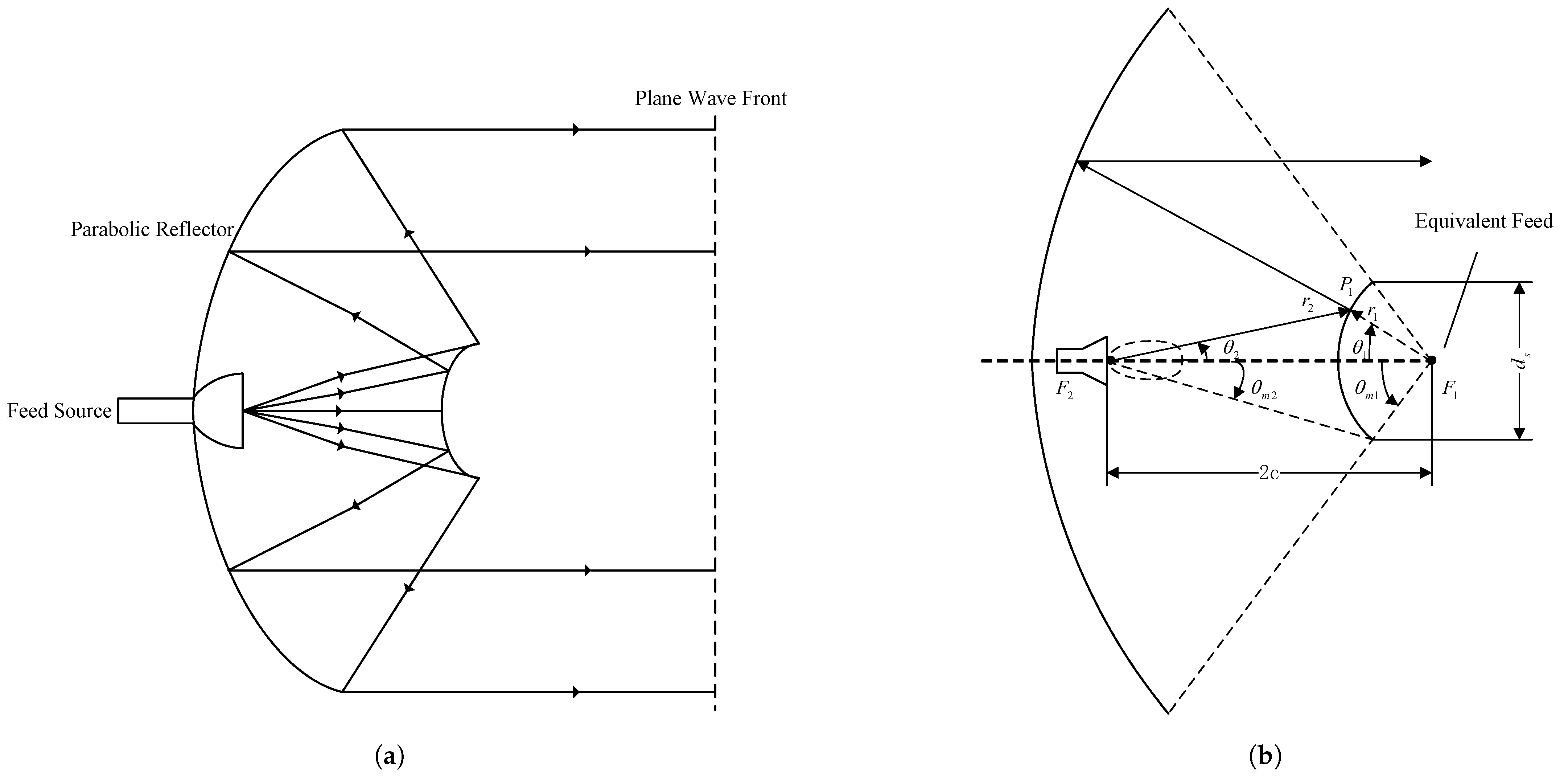
2.1. Basic Principles of Reflector Antennas

Spaceborne SAR systems utilize various types of antennas, primarily including planar phased array antennas and reflector antennas. The selection of an appropriate antenna type depends on mission requirements, satellite platform capabilities, and SAR system performance. Due to its high gain and low sidelobe characteristics, reflector antennas are advantageous for achieving high-resolution imaging in spaceborne SAR applications. Among various reflector antenna types, the rotationally symmetric parabolic reflector antenna is the most common.
The simplest form of a reflector antenna typically consists of two main components: a reflector surface significantly larger than the operating wavelength and a relatively small feed. Figure 1 illustrates the structural schematic of a parabolic reflector antenna.
The vertex of the paraboloid is denoted as O , and the focal point is located at F. A symmetric parabolic reflector is fully defined by its diameter d and focal length f, and it is typically characterized by its f / d ratio. The diameter d represents the physical size of the reflector, while the f / d ratio describes its curvature. As f / d approaches infinity, the reflector surface approximates a planar surface. A rotationally symmetric paraboloid is generated by rotating a parabolic curve about its axis of symmetry. Any point on its surface satisfies the following equations [20]:
In cylindrical coordinates (origin at O ):
ρ 2 = 4 f z
where f is the focal length of the paraboloid, ρ is the radial distance from point M on the paraboloid to the z-axis, and z is the axial coordinate along the paraboloid’s symmetry axis.
In rectangular coordinates (origin at O ):
x 2 + y 2 = 4 f z
In comparison, a more convenient coordinate system for application is the spherical coordinate system with the focus F as the origin. The spherical coordinates of an arbitrary point M on the parabolic surface are denoted as ( r , θ , φ ) ; thus,
r sin θ = ρ
r cos θ = f z
where r is the distance from the focus F to an arbitrary point M on the reflector surface, and θ is the angle between r and the z-axis.
The sum of the squares of the above two equations is obtained as follows:
r = ρ 2 + ( f z ) 2 = 4 f z + f 2 2 f z + z 2 = f + z = 2 f r cos θ
Therefore,
r = 2 f 1 + cos θ = f cos 2 θ 2
This is the spherical coordinate equation of a point on the parabolic surface with point F as the origin. The geometric parameters of the paraboloid include the diameter d, focal length f, and the half opening angle θ m . Since
ρ = r sin θ = f cos 2 θ / 2 2 sin θ 2 cos θ 2 = 2 f tan θ 2
we have
d 2 = 2 f tan θ m 2
or
tan θ m 2 = d 4 f
where θ m is the half opening angle of the paraboloid.
It follows that among these three parameters, only two are independent. Specifying any two uniquely determines the shape of the paraboloid. Similarly, based on the principle of geometrical optics, when a point source is positioned at the focal point F, the reflected waves from the parabolic surface propagate parallel to the axis, forming a collimated beam (plane wave).

2.2. Types and Characteristics of Reflector Antennas

Reflector antennas can be classified based on their characteristics. The most fundamental classification is based on the geometric shape of the reflector. According to this criterion, reflector antennas can be categorized into five types [21]: parabolic reflector antennas, parabolic cylindrical antennas, elliptical reflector antennas, spherical reflector antennas, and dual-reflector antennas. The characteristics and applications of each type are discussed below.

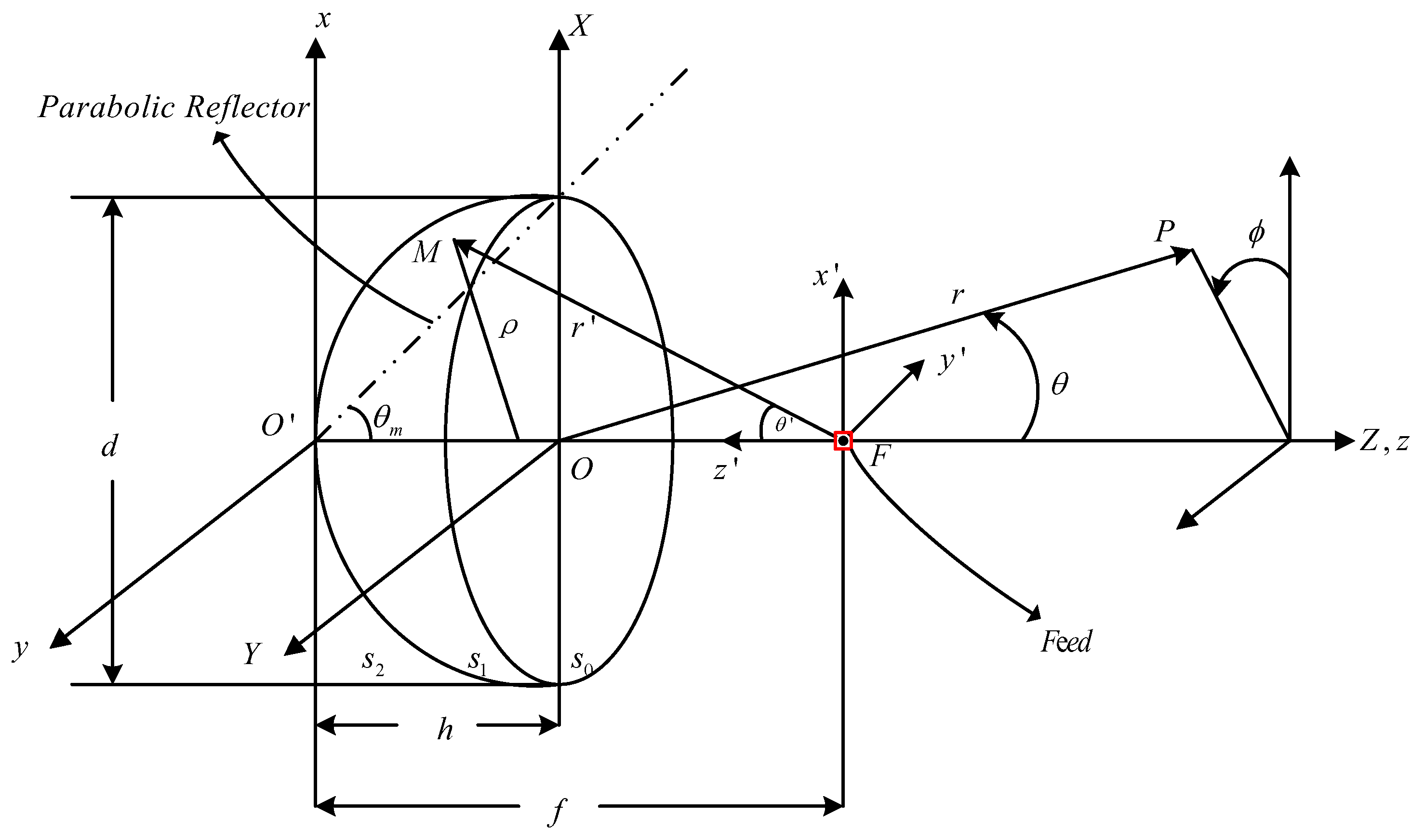
2.2.1. Parabolic Reflector Antennas

Parabolic reflector antennas, or rotational parabolic antennas, operate based on the principles described in Section 2.1. As the most classic and widely used type of reflector antenna [22], its geometry ensures that parallel incoming waves converge at the focal point. In radar systems, it offers high gain, strong directivity, high efficiency, and low sidelobe levels [23].
A key parameter is aperture gain, given by
G = 4 π A λ 2
where A is the aperture area and λ is the wavelength. For a circular aperture with diameter D, this becomes
G = π D λ 2
In practice, gain is reduced by losses such as spillover, feed blockage, reflector leakage, surface deformation, and structural blockage. These factors must be considered in design and analysis.
Parabolic reflector antennas are widely used due to their simple structure, ease of design and fabrication, and excellent electromagnetic performance. However, they inherently suffer from certain drawbacks: the feed and their supporting struts are typically positioned along the antenna’s optical axis, which results in scattering and blockage of the reflected electromagnetic waves. Consequently, feed blockage leads to reduced antenna gain and increased sidelobe levels, thereby degrading overall performance.
Offset reflector antennas address this by using an asymmetric reflector, placing the feed outside the aperture. This configuration eliminates feed blockage, thereby improving antenna gain and efficiency [24]. Offset reflector antennas significantly enhance aperture efficiency, reduce sidelobe levels, and improve cross-polarization performance. As illustrated in Figure 2, the offset reflector antenna places the feed outside the main reflector aperture to reduce feed-induced obstructions, thereby improving the antenna’s overall performance [25]. Geometrically, an offset reflector is a section of a larger paraboloid, formed by intersecting a conventional parabolic reflector with a cylinder offset from the focal axis. This design removes feed blockage but, due to its asymmetry, may increase cross-polarization.
In SAR applications, parabolic reflectors are most suited for narrow-swath, high-resolution imaging due to their high gain and well-formed main lobe. However, they suffer from feed blockage and increased sidelobe levels, especially when large apertures are needed. These limitations can reduce imaging contrast and interfere with clutter suppression.

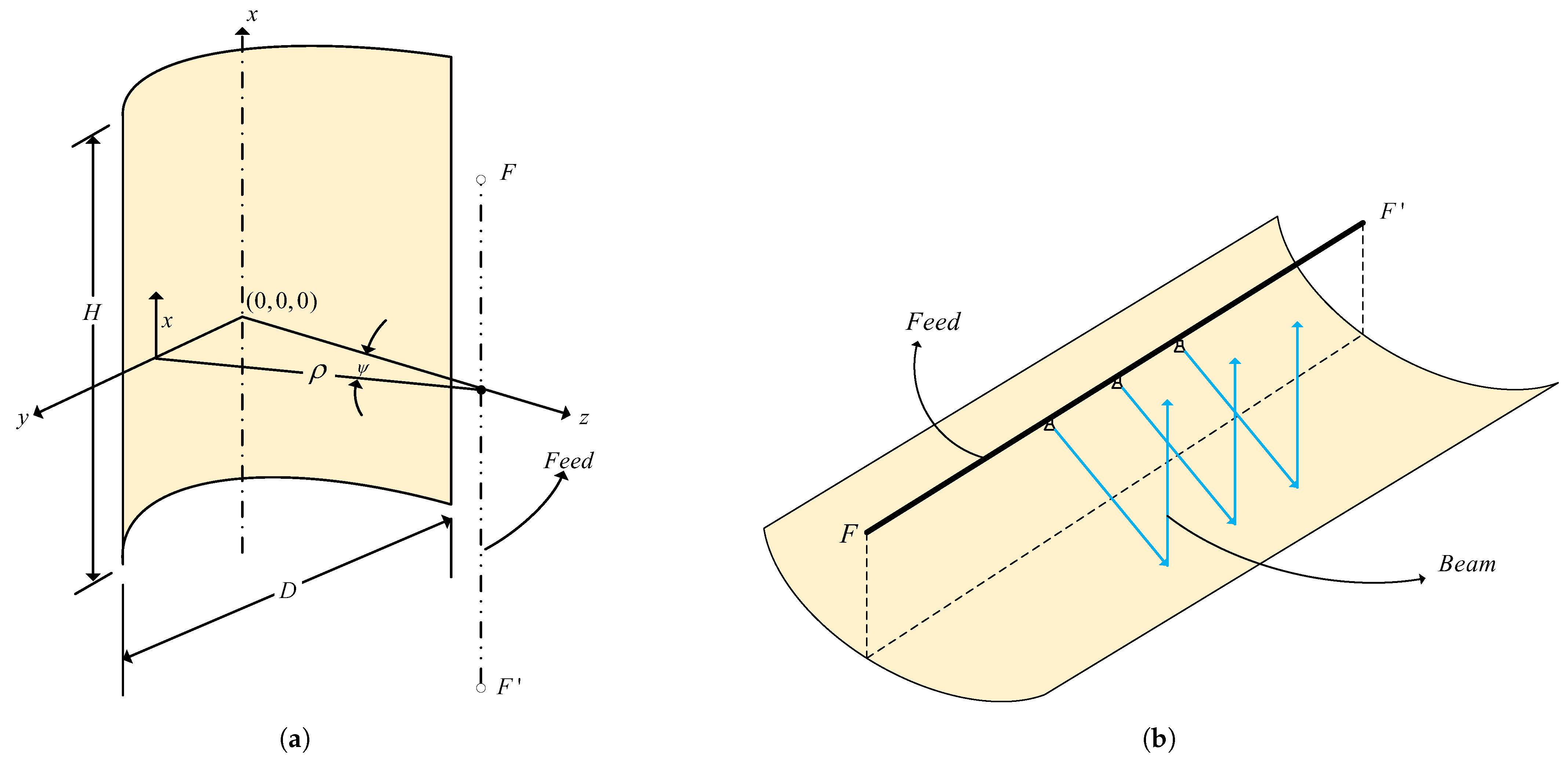
2.2.2. Parabolic Cylindrical Reflector Antennas

The primary difference between a parabolic cylindrical reflector antenna and a rotational parabolic reflector antenna lies in their formation: a rotational parabolic reflector is generated by rotating a parabolic curve around its axis, while a parabolic cylindrical reflector antenna is formed by translating a parabolic curve along its normal direction to create a cylindrical surface. Parabolic cylindrical reflectors focus in one direction and produce a fan-shaped beam in the other, making them suitable for scanning radar systems with mechanical or electronic beam steering.
The surface of a parabolic cylindrical reflector is defined by the following equation:
z = y 2 4 f f
where z is the distance from the focal plane, f is the focal length, and y is the horizontal dimension. A basic configuration of a parabolic cylindrical reflector is shown in Figure 3a; the shape is constant along the x-axis, and the feed is typically a line source placed along the focal line. As we can see from Figure 3b, the beam of the linear feed is also linear, and at any cross-section, the beam direction is consistent with the rotating parabolic surface.
The design principles of parabolic cylindrical reflector antennas are similar to those of parabolic reflectors, with the primary distinction being that the energy from the feed propagates in a cylindrical wavefront rather than a spherical one. Consequently, parabolic cylindrical reflectors exhibit a simple structure and unidirectional focusing characteristics, though they tend to be larger and offer reduced flexibility. In SAR applications, parabolic cylindrical reflector antennas can be employed in stripmap-mode SARs to achieve high-azimuth-resolution imaging while maintaining a certain level of range coverage.
This antenna type is ideal for stripmap SAR and ground surveillance, as it naturally generates a wide beam in one direction, offering wide coverage. However, the lack of focusing in the orthogonal direction limits its use in spotlight or high-resolution imaging modes. Further beamforming is often needed to enhance performance.

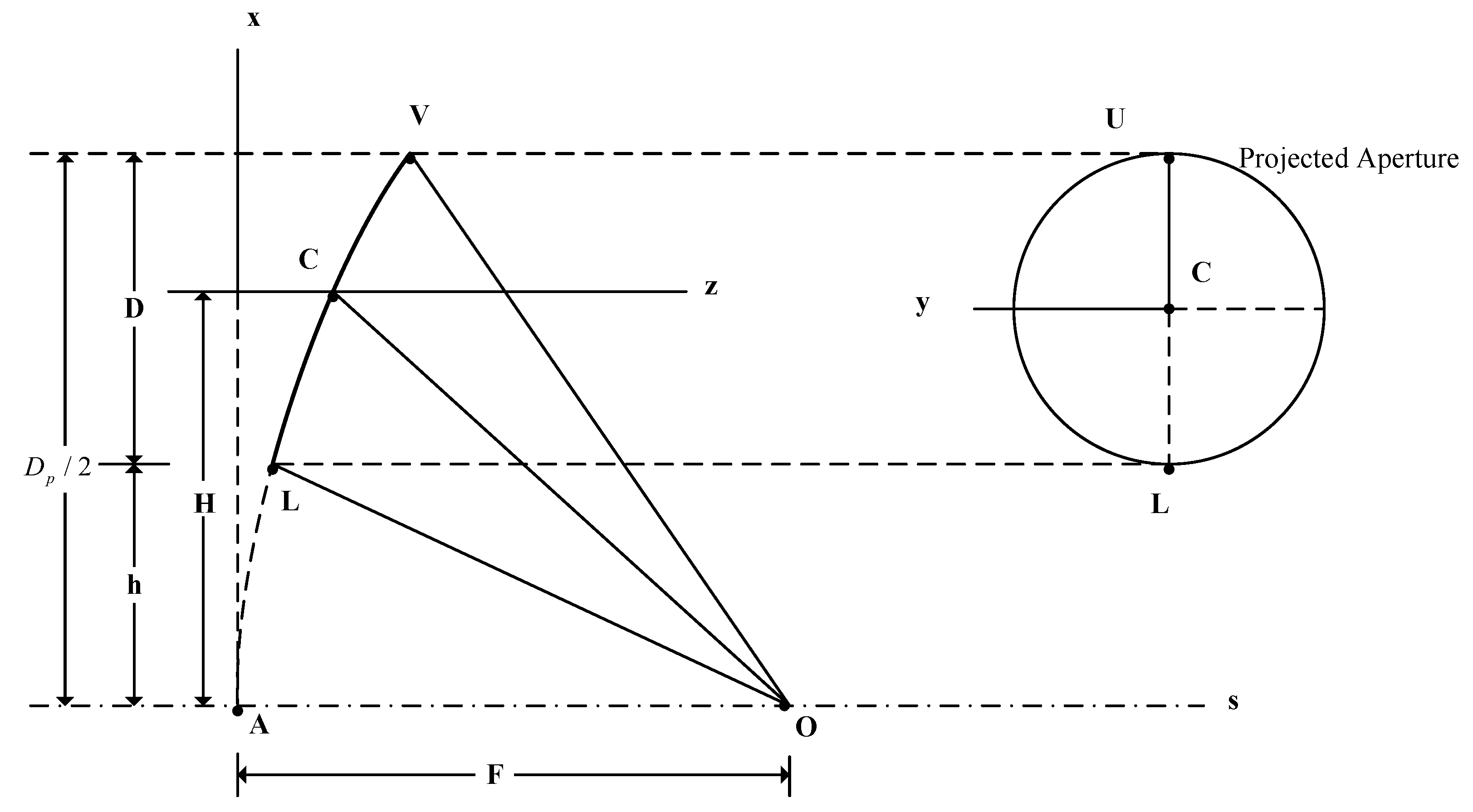
2.2.3. Elliptical Reflector Antennas

Elliptical reflector antennas use an ellipsoidal surface to focus signals, differing from parabolic reflectors by having two distinct focal lengths in orthogonal directions (azimuth and range). As shown in Figure 4a, rays from one focal point reflect to the other, enabling dual-focus operation. The reflector surface is as follows:
Z = x 2 4 F a + y 2 4 F r
where F a and F r are the focal lengths in the x and y directions, respectively.
The ellipsoidal geometry enables beam shaping, improved gain distribution, enhanced directivity, and sidelobe control. Although less common in spaceborne SAR systems, elliptical reflectors are valuable for applications requiring custom beam patterns or multi-beam scanning.
In spaceborne SAR systems, elliptical reflector antennas are mostly used in conjunction with one-dimensional linear phased array feeds. As shown in Figure 4b, the phased array feed is placed on the azimuth focus F 1 ; for the range direction, it is located at the forward out-of-focus position. Elliptical reflector antennas offer dual-focus operation, making them suitable for applications requiring shaped or multi-beam coverage, such as wide-swath monitoring. However, the complex geometry imposes challenges in surface accuracy control and mechanical deployment.

2.2.4. Dual-Reflector Antennas

A dual-reflector antennas is an extended configuration of a parabolic reflector antenna system that incorporates a secondary reflector. The most common forms include the Cassegrain antenna and the Gregorian antenna. Originating from optical telescope designs, the Cassegrain antenna is the most prevalent dual-reflector configuration, as illustrated in Figure 5a. Its standard structure consists of a primary parabolic reflector and a secondary hyperbolic reflector, both formed by rotating a parabola and a hyperbola about their respective axes.
In operation, electromagnetic waves from the feed reflect off the secondary reflector, then the primary reflector, and finally propagate outward. Similar to a conventional parabolic reflector antenna, the rays originating from the feed remain parallel to the optical axis after two reflections.
To better understand the operation of a Cassegrain antenna, the equivalent feed method (also known as the virtual feed method) can be employed. As shown in Figure 5b, using a geometric optics approximation, rays emitted from the real feed F 2 are reflected by the secondary reflector in such a way that they appear to originate from a virtual focal point F 1 . This implies that the combination of the real feed and the secondary reflector can be equivalently represented as a single virtual feed located at the virtual focal point. Consequently, a Cassegrain antenna with a reduced longitudinal dimension can achieve the same performance as a long-focal-length parabolic reflector antenna, thereby reducing the overall length while maintaining an effective focal distance.
Dual-reflector designs reduce the distance between the feed and transceiver, minimizing noise. The dual reflections also enable the use of symmetric feed patterns, improving aperture field distribution and overall efficiency. Positioning the feed behind the primary reflector further reduces feed blockage. Despite added complexity, the dual-reflector antenna offers key advantages: reduced blockage, improved aperture efficiency, aberration correction, better beam shaping, and lower sidelobe and cross-polarization levels [25,26].
Dual-reflector designs such as Cassegrain and Gregorian antennas are valuable when compact feed placement and high aperture efficiency are required. They are especially suitable for missions requiring symmetric beam shaping and low cross-polarization. However, their structural complexity increases deployment risk and cost in spaceborne SAR applications.

2.2.5. Spherical Reflector Antennas

Spherical reflector antennas use a segment of a spherical surface and are suited for wide-angle scanning or multi-beam applications [27]. Within a limited angular range, the spherical surface approximates a paraboloid, enabling beam steering as the feed moves along a surface of radius R / 2 . The scanning range depends on the reflector’s aperture size, and beam steering can be realized via movable or switchable feed arrays.
Owing to the symmetry of the spherical geometry, feed movement near the focal region causes minimal performance loss. However, spherical reflectors inherently suffer from aberrations, leading to reduced gain and aperture efficiency. These can be mitigated using corrective feeds or dual-reflector designs. Though rarely used in SARs, spherical reflector antennas are promising for systems requiring wide-angle or multi-beam coverage, such as phased-array radar and multi-beam SARs.
While spherical reflectors allow for wide-angle scanning through mechanical feed movement, their inherent aberrations and reduced gain make them less favorable for high-resolution SARs. Corrective techniques such as dual-reflector correction or adaptive feeds are needed to improve performance, but they add to system complexity.

2.2.6. Summary of Reflector Antenna Types and Characteristics

Different reflector antenna types offer distinct advantages tailored to specific applications. Parabolic reflectors are widely used in satellite communications and radio astronomy for their high gain and simple design, while offset reflectors eliminates feed blockage, enhancing gain and efficiency in radar and satellite systems. Parabolic cylindrical reflectors provide high-resolution imaging and are effective in scanning radar systems. Elliptical reflectors, with dual foci, enable flexible beam shaping for multi-beam and pattern-specific radars. Dual-reflector designs, such as Cassegrain antennas, improve aperture efficiency and reduce feedline loss. Spherical reflectors support wide-angle and multi-beam coverage, making them suitable for radio astronomy and multi-target tracking. Table 1 summarizes the main characteristics of these five types of reflector antennas and their representative application examples in existing spaceborne SAR systems.
From a comparative perspective, each reflector antenna type presents distinct trade-offs between electromagnetic performance, structural complexity, and system-level applicability. Parabolic reflector antennas offer high gain and are widely used in conventional SAR systems, but suffer from feed blockage, especially at larger apertures. Offset designs mitigate this issue at the expense of increased structural asymmetry. Parabolic cylindrical reflector antennas, while structurally simple and effective for wide-area scanning, lack focusing capability in the orthogonal direction, making them unsuitable for high-resolution spotlight imaging. Elliptical reflector antennas enable dual-focus beam shaping and multi-beam operations but introduce challenges in manufacturing precision and mechanical deployment. Dual-reflector antenna configurations enhance aperture efficiency and beam symmetry while reducing feed blockage and cross-polarization, though their mechanical complexity increases deployment risk. Spherical reflector antennas are advantageous in wide-angle and multi-beam scenarios but require correction techniques to overcome inherent aberrations and reduced gain.
Ultimately, the selection of the reflector antenna type in spaceborne SAR systems must balance resolution, swath width, weight, deployability, polarization performance, and cost. Scientific missions may prioritize imaging quality and flexibility, favoring complex dual-reflector or elliptical systems, whereas commercial platforms often favor robustness and compactness, leaning toward traditional or offset parabolic reflector antennas. This classification not only supports structural taxonomy but also serves as a design guideline in aligning antenna architecture with mission-specific SAR imaging requirements.

3. Reflector Antenna Configurations in Spaceborne SAR Systems

The current spaceborne SAR systems mainly adopt parabolic reflector antennas, elliptical reflector antennas and dual-reflector antennas as their antenna forms. Table 1 lists the specific system examples. Below, we will conduct a detailed discussion based on their deployment mechanisms and feed configurations.

3.1. Deployable Antenna

Spaceborne SAR systems require large-aperture antennas. Therefore, the application of deployable antennas is more in line with the trends of high gain and lightweight design [26,28,29]. When the satellite is launched, the antenna is folded up and then deployed in orbit. Figure 6 illustrates the deployable antenna of HJ-1-C [30], where Figure 6a is the antenna folded state and Figure 6b is the antenna deployed state. According to the way the antenna is folded up and deployed, deployable antennas can be classified into the following three categories: framework deployable antennas, perimeter truss deployable antennas, and radial rib deployable antennas [31,32,33]. In the following sections, we will present an overview of the three types of deployable antennas.

3.1.1. Framework Deployable Antenna

A framework deployable reflector antenna employs a spatial framework composed of interconnected rods and nodes, forming a grid-like structure. This configuration adopts a modular design approach [34], using elements such as tetrahedrons, quadrangular pyramids, hexagonal prisms, and hexagonal frusta. By adjusting the module quantity and size, apertures of various dimensions can be realized. Deployment is typically enabled through hinged trusses with spring-loaded mechanisms [35], offering a high stowage ratio (typically around 1:10), high surface precision, and stable deployment performance.
Framework antennas provide high structural rigidity, lightweight design, and wideband capability [36]. Compared to other large deployable antenna types, they demonstrate superior deployment stiffness, excellent thermal stability, and scalability for on-orbit assembly [37].
Key advantages of this configuration include simplified structural design, reliable deployment mechanisms, and accurate surface control. However, challenges remain, notably the complex assembly and calibration due to numerous rods and joints. Additionally, a non-uniform weight distribution can impact antenna pointing accuracy and satellite attitude stability.
Despite these limitations, framework deployable antennas are often used to meet the requirements of large apertures and broadband. Representative examples include China’s HJ-1-C SAR satellite (launched in 2012 under the “2+1” disaster monitoring constellation, as illustrated in Figure 7a), the Ku-band Qilu-1 SAR satellite (launched in 2021), and Russia’s Kondor-FKA SAR satellite (illustrated in Figure 7b), all of which utilize framework deployable reflectors.

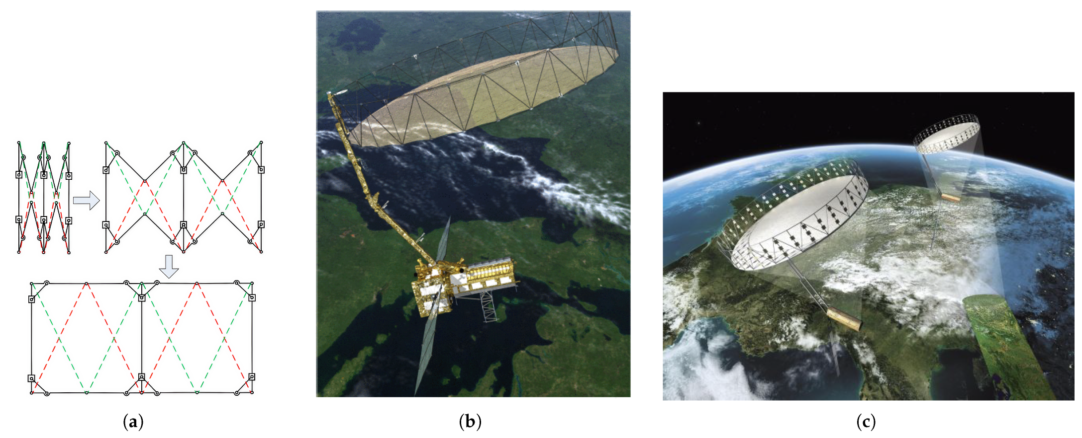
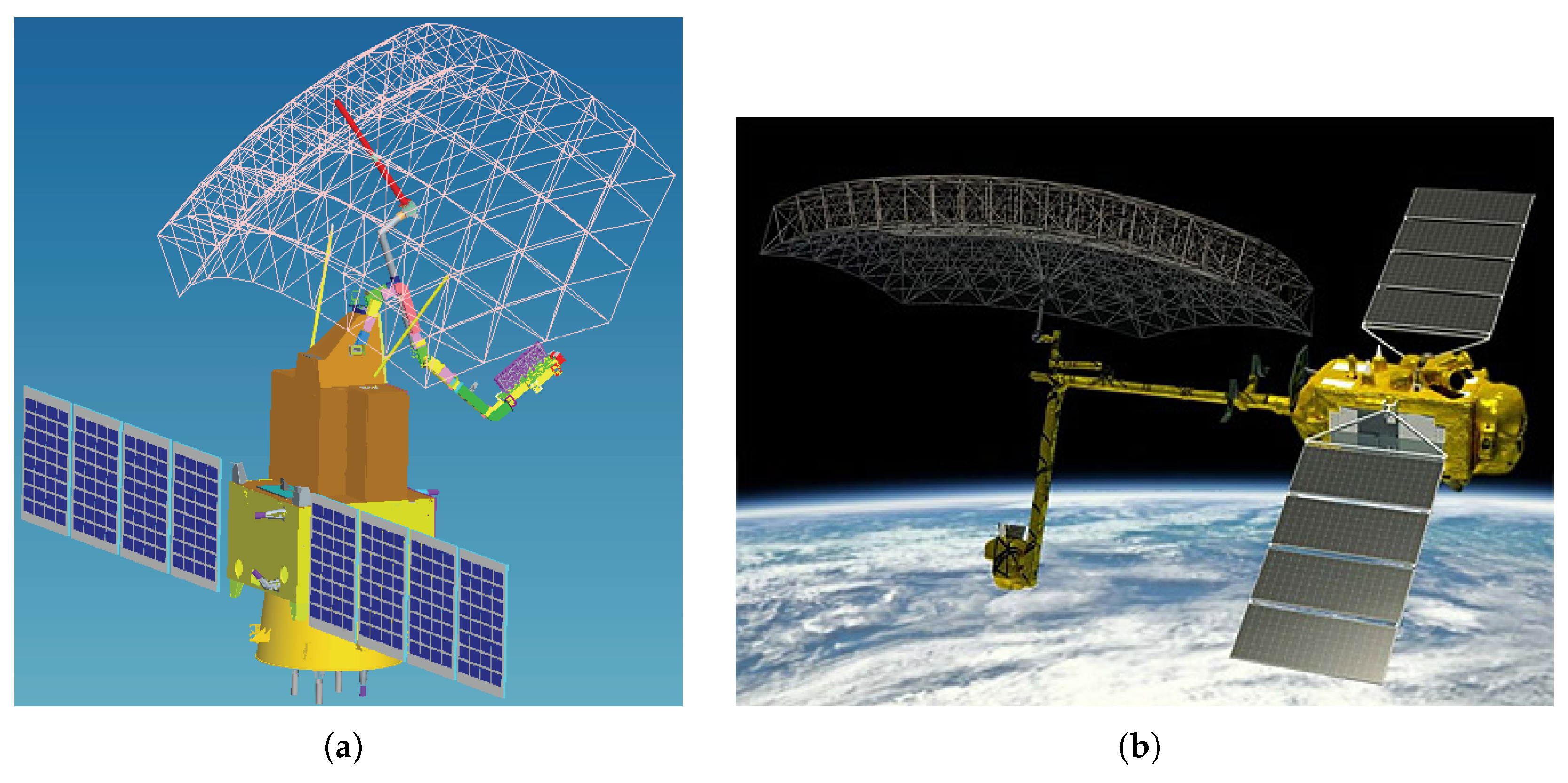
3.1.2. Perimeter Truss Deployable Antennas

Perimeter truss deployable reflector antennas, or ring truss antennas, consist of a circular truss and a flexible cable-net reflector. Deployment arms drive the antenna into position, where the truss expands to tension the mesh and form the reflector surface [40]. The structure includes quadrilateral units with telescopic diagonals, and cables threaded through the diagonals contract them synchronously during deployment [41,42]. The deployment process of the perimeter truss deployable antenna is illustrated in Figure 8a. This configuration offers a high deployment ratio, good structural precision, and relatively uniform weight distribution. Compared to framework antennas, it is simpler and lighter, making it well suited for spaceborne SAR systems requiring compact stowage and reliable deployment.
For example, the Acadia satellite series, representing Capella Space’s latest generation of X-band SAR satellites, employs an 8 m2 perimeter truss deployable antenna as part of its new constellation launched in 2023 [19]. Germany’s Tandem-L mission, proposed by the German Aerospace Center (DLR), also utilizes a perimeter truss reflector to enable high-resolution, wide-swath imaging. Tandem-L is an L-band fully polarimetric bistatic SAR constellation designed for real-time monitoring of dynamic Earth processes, including global biomass mapping, surface deformation, and disaster response [43,44,45,46,47,48,49,50]. The NASA-ISRO Synthetic Aperture Radar (NISAR) mission, a joint initiative between NASA and ISRO, consists of two fully polarimetric SAR satellites operating in the L- and S-bands, respectively [16,51]. NISAR features a 12-m diameter perimeter truss deployable reflector, as illustrated in Figure 8b. Another example is EOS SAR, developed by EOS in the United States, which operates in the X- and S-bands and integrates a lightweight perimeter truss reflector antenna with a total SAR payload mass of 50 kg. Meanwhile, the Tandem-L in Germany also adopts a peripheral truss deployable antenna, as illustrated in Figure 8c.
Figure 8. Perimeter truss deployable antenna: (a) deployment process [52]; (b) NISAR satellite [16]; (c) Tandem-L satellite [53].
Remotesensing 17 02432 g008

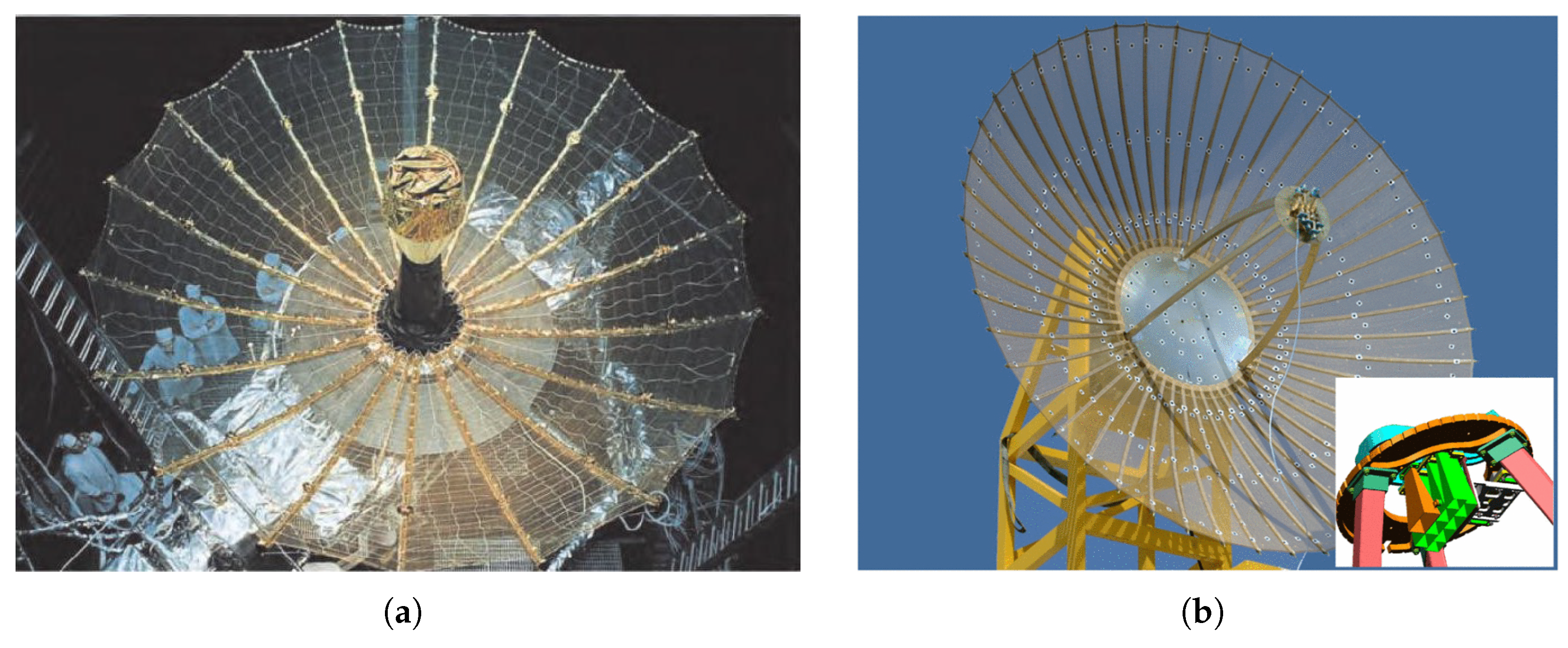
3.1.3. Radial Rib Deployable Antennas

Radial rib deployable reflector antennas, also known as star-rib antennas, are a well-established configuration widely used in spaceborne systems [34,54,55]. Structurally similarly to an umbrella, they comprise multiple curved carbon-fiber parabolic ribs attached to a central hub, supporting a metal mesh reflector. When stowed, the ribs fold along the central axis. During deployment, motors drive the ribs to unfold radially around the hub. The reflective mesh is tensioned by a cable-net structure stretched over the deployed ribs. When retracted, the ribs fold inward via a base mechanism into a compact cylindrical shape. Once deployed, the antenna resembles a fully opened umbrella, as illustrated in Figure 9a. This configuration uses a centralized mechanism to deploy ribs radially, forming the reflector surface through interconnecting cables. It offers a simple structure, reliable deployment, and low weight, making it suitable for large spaceborne antennas and promising for SAR applications.
For example, Israel’s TecSAR satellite, launched in 2008 [14,56], adopts a radial rib antenna and employs mosaic scanning, combining electronic and mechanical methods to achieve high-resolution imaging across wider coverage areas (see Figure 9b). India’s RISAT-2 series, launched by ISRO in 2009, also uses radial rib antennas and supports multiple imaging modes. Japan’s QPS-SAR, launched in 2019, features a 3.6-m diameter antenna that folds into a compact 0.8-m diameter and 0.15-m height. In 2024, China’s Neptune-01 was launched with a radial rib deployable reflector antenna for use in resource monitoring, disaster management, environmental protection, and maritime security.

3.1.4. Summary of Deployable Antennas

Framework-based, perimeter truss-based, and radial rib-based deployable antennas each offer unique advantages for different applications.
(1) Framework deployable antennas utilize a modular truss design, forming a spatial grid through interconnected rods and nodes. They offer a high stowage ratio, precision, and deployment stability with strong structural rigidity, making them suitable for large aperture and high-bandwidth applications. However, their complex assembly and uneven weight distribution may impact performance.
(2) Perimeter truss deployable antennas use a ring truss and cable-net reflector, resulting in a lightweight, high-stowage-ratio structure with uniform weight distribution and simplified deployment mechanisms. They effectively balance the deployment ratio, structural stability, and mass distribution, making them ideal for next-generation SAR satellites.
(3) Radial rib deployable antennas rely on a central deployment mechanism with outward-extending ribs, offering simplicity, reliability, and lightweight characteristics. They are particularly suited for large spaceborne antennas and high-resolution SAR missions.
Table 2 summarizes the SAR satellite missions that employ different types of deployable antennas.

3.2. Feed Configurations for Reflector Antenna

Specifically, in the transmission mode, the feed generates a primary beam that illuminates the reflector surface, which then shapes and directs the radiation toward the target region. In the reception mode, backscattered signals from the target are first collected and focused by the reflector before being received by the feed and transmitted to the receiver system. Generally speaking, the feeds of reflector antennas in spaceborne SAR systems are classified into the following three categories: single-beam feed, multi-beam feed, and phased array feed (PAF).
Reflector antennas work with a feed on the focus or near the focus. Single-beam feed is commonly used due to its simple structure and ease of implementation, which suffices for many basic SAR applications. However, as SAR technology advances toward HRWS imaging and there are increasing demands for multi-polarization and multi-beam capabilities, the limitations of single-beam feeds have become apparent.
To overcome these constraints, researchers have explored more complex feed architectures, such as multi-beam feed and phased array feed (PAF). Multi-beam feed can generate multiple independent beams simultaneously, enabling wider area coverage and parallel multi-channel reception, thereby improving mapping efficiency and supporting multi-beam SAR. One feed forms an antenna beam, so it needs to be switched to a phased array feed to achieve beam scanning. Phased array feed, leveraging electronic scanning technology, offers flexible beam steering and shaping, allowing for rapid beam scanning and dynamic beamforming. These features make PAF well suited for high-resolution, wide-swath SAR imaging and complex scene observations.
The following sections introduce the three primary feed configurations used in spaceborne SAR reflector antenna systems.

3.2.1. Single-Beam Feed

Single-beam feed is the most fundamental and widely used feed type in reflector antennas. Traditional reflector antennas, such as parabolic antennas, typically use a single-beam feed, often implemented as a horn antenna. The primary beam generated by the feed is shaped by the reflector to form a directed beam. The primary objective in single-beam feed design is to produce an initial radiation pattern with optimal characteristics to efficiently illuminate the reflector and maximize overall antenna performance.
While single-beam feed reflector antennas lack beam-scanning capability, they remain suitable for many basic SAR applications, particularly those with relatively simple operational requirements. For example, Qilu-1, a Chinese SAR satellite launched in 2021, utilizes a single-beam reflector antenna to provide remote sensing services for land monitoring, urban planning, agriculture, forestry, energy, and disaster management in the Shandong region of China. Meanwhile, the Capela Arcadia SAR satellite [19] of Capela Space in the United States also adopted the traditional single-beam feed. As illustrated in Figure 10, the horn antenna in the red box represents a single-beam feed.

3.2.2. Multi-Beam Feeds

Compared to single-beam feeds, multi-beam feeds can generate multiple independent beams simultaneously, providing benefits such as expanded spatial coverage, increased data transmission capacity, and support for multi-functional radar systems. The key advantages of multi-beam antennas include the following:
(1) Increased System Capacity—By utilizing spatial and polarization isolation, multi-beam antennas enable frequency reuse, significantly enhancing bandwidth utilization and communication capacity.
(2) Enhanced Antenna Gain.
(3) Greater Flexibility—Multi-beam antennas offer beam scanning and beam reconfiguration capabilities.
Multi-beam reflector antennas often employ an array of offset feeds, typically consisting of multiple horn antennas, to illuminate the reflector and generate multiple beams. This configuration is also known as a reflector-fed feed array multi-beam antenna. As shown in Figure 11a, the multi-beam feed of RISAT-2 [57] uses an array of multi-beam feeds. In Figure 11b, we can see that the multi-beam feeds of HJ-1-C [30] can generate nine different beams.
Since multi-beam reflector antennas can achieve high-gain, multi-beam operation with relatively small feed arrays, they reduce the complexity of the system. Consequently, multi-beam feeds have been widely adopted in SAR applications. Examples include TecSAR (Israel, 2008) [14,56], RISAT-2 series (India, 2009) and HJ-1-C (China, 2012) [18].

3.2.3. Phased Array Feed (PAF)

The PAF technique combines the beam-scanning and beamforming capabilities of phased arrays with the high-gain characteristics of reflector antennas, offering an advanced solution for high-performance radar and communication systems. In spaceborne SAR applications, PAF reflector antennas provide HRWS imaging with flexible beam control, making them a key development direction.
PAF reflector antennas typically adopt a hybrid architecture, where the phased array feed illuminates the reflector, enabling beam agility and dynamic adjustments to meet the demands of high-resolution SAR. Unlike multi-beam feeds described in Section 3.2.2, which require complex high-power feed-switching networks to achieve multiple beams of different widths and directions required for SARs, the reflector antenna with PAF has the advantages of both phased array antennas and reflector antennas, mainly in the following aspects [58]:
(1) Improved System Reliability—The distributed transmission of a PAF ensures that all beams are formed simultaneously by all feed elements, eliminating the need for high-power microwave switches or feed-switching networks, thereby improving system reliability.
(2) Reduced Feed Losses—PAF designs allow transmission/reception (T/R) components to be placed closer to the horn elements, reducing feed loss and enhancing antenna efficiency [59,60].
(3) Enhanced Beam Flexibility—By applying amplitude and phase weighting to feed elements, PAF reflector antennas can achieve limited electronic scanning and beam broadening, offering greater flexibility than multi-beam reflector antennas [61,62].
Although the PAF technique is still relatively uncommon in SAR applications, China’s environmental and disaster monitoring satellites (HJ-2-E/F) have adopted a one-dimensional phased array feed, with its basic configuration shown in Figure 12. The PAF technique introduces new capabilities to reflector antennas, such as beam scanning, beamforming, and multi-beam generation, significantly expanding their applicability. In spaceborne SAR systems, PAF reflector antennas offer great potential for HRWS imaging, adaptive beam control, and multi-functional SAR operations. As technology advances, PAF-based reflector antennas are expected to play an increasingly important role in future spaceborne SAR systems.

3.2.4. Summary of Feed Configurations for Reflector Antennas

Reflector antennas have various configurations, each with distinct advantages and trade-offs. The choice of feed architecture in spaceborne SAR systems depends on the specific mission requirements.
(1) Single-beam feed is the most common, featuring a single horn antenna to generate a directional beam, while simple and cost-effective, it lacks beam-scanning capabilities, making it only suitable for basic SAR applications.
(2) Multi-beam feeds can simultaneously generate multiple independent beams, expanding coverage, enhancing data transmission, and enabling beam scanning and reconfiguration. However, their scanning angles are limited and discontinuous, making them less flexible than PAF.
(3) The phased array feed, combined with the beam scanning of the phased array antenna and the high-gain characteristics of the reflector antenna, can achieve flexible beam control. Therefore, they are suitable for HRWS imaging, avoid complex feed switching networks, improve system reliability and efficiency, and have broad potential in the future SAR field.
Table 3 summarizes the characteristics and SAR applications of these three feed configurations.

3.3. Reflector Antenna Configurations in Representative SAR Systems

Reflector antennas have been widely adopted in a variety of spaceborne SAR missions due to their high gain and beam shaping flexibility. Depending on specific mission objectives, different reflector structure types and feed configurations have been developed. This section summarizes the reflector antenna configurations of selected current and upcoming SAR systems, categorized according to the reflector deployment mechanisms and feed types, as defined in Section 2. Specifically, three classes of deployable reflectors—radial rib deployable antennas, framework deployable antennas, and perimeter truss deployable antennas—are identified, along with three types of feed systems: single-beam feed, multi-beam feeds, and phased array feed. Table 4 provides an overview of representative SAR missions and highlights their antenna configurations and system characteristics.
Overall, the adoption of different reflector structures and feed types reflects the trade-offs between system complexity, imaging performance, and deployment constraints. Scientific missions tend to favor advanced configurations such as perimeter truss deployable antennas and multi-beam feeds to achieve wide-swath and high-resolution capabilities, while commercial systems often prioritize compactness and cost-effectiveness through simpler designs.

4. Challenges and Development Trends in Reflector Antenna-Based SAR Technology

4.1. Emerging Techniques for Reflector Antenna-Based SAR

To achieve HRWS imaging, some emerging techniques have been applied in current spaceborne SAR systems. These emerging techniques are also combined with reflector antennas, mainly including the following three: digital beamforming (DBF), staggered SAR, and SweepSAR. This section provides an in-depth analysis of these emerging techniques.

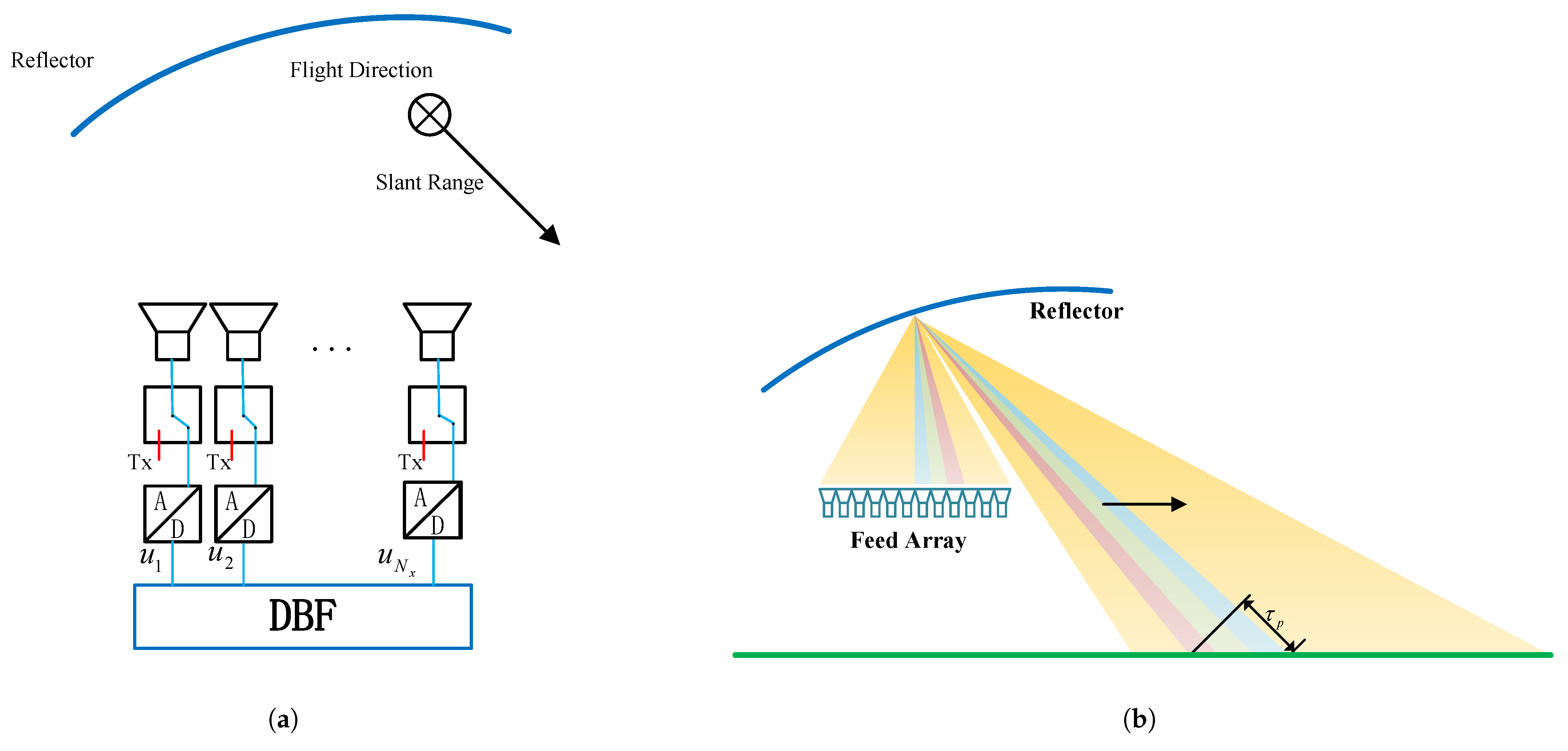
4.1.1. Reflector Antennas with DBF

To achieve wide-swath imaging, spaceborne SAR systems often require reduced antenna sizes in the range direction. However, the minimum antenna area constraint [63] limits size reduction, as decreasing the antenna size also reduces transmission gain, negatively impacting the signal-to-noise ratio (SNR). Additionally, broad beam formation in the range direction exacerbates range ambiguities [64]. Traditional DBF [65] mitigates these challenges by dividing the antenna into multiple sub-apertures in the range direction. During transmission, a single aperture generates a broad beam for wide-swath coverage, while each sub-aperture independently receives echoes from different ground regions. DBF then applies time-variant weighting to the received signals, effectively emulating a dynamic high-gain narrow beam for ground echo reception—a concept known as Scan-On-Receive (SCORE) [66,67,68]. Compared to conventional analog beamforming methods, DBF provides greater flexibility, precision, and multi-beam processing capabilities [69,70]. This single-transmit, multi-receive mechanism successfully achieves the goal of HRWS SAR imaging.
In recent years, the integration of reflector antennas with DBF has become a promising trend in spaceborne SAR systems. This combination leverages the high gain and efficiency of reflector antennas while incorporating DBF’s beamforming flexibility and precision control, offering a viable solution for HRWS SAR systems [15,70,71,72]. However, implementing DBF with a reflector antenna requires the use of PAF. Compared to planar phased array antennas, reflector antennas provide superior gain performance [70] and enable HRWS imaging. Unlike planar phased arrays, which directly receive signals, reflector antennas capture echoes via their feed elements after signal reflection.
Figure 13a shows a typical reflector-based DBF SAR system architecture [73]. During transmission, all feed elements are activated to generate a broad beam, which illuminates a specific ground area. In reception, different ground regions correspond to specific feed elements, forming a wide-transmit, narrow-receive configuration. This mechanism is similar to the SCORE technique, wherein high-gain narrow sub-beams track ground echoes dynamically [70,74,75], as depicted in Figure 13b. By incorporating the DBF technique, reflector antenna-based SAR systems can achieve HRWS imaging while reducing the complexity of large-aperture beamforming processors, improving overall system efficiency [69].
Compared to conventional planar phased array DBF SAR systems, reflector antenna-based DBF SAR systems offer several advantages:
(1) Lower Weight, Simpler Structure and Cost-Effectiveness—For a given aperture and gain, reflector antennas are generally lighter and structurally simpler, making them well suited for large-scale, spaceborne HRWS SAR systems.
(2) Larger Aperture Capabilities—Reflector antennas can accommodate larger apertures, resulting in higher resolution and gain. When combined with DBF, they enable flexible beam scanning and multi-beam imaging, thereby extending the swath width while maintaining a high resolution.
Thus, the integration of reflector antennas with the DBF technique represents a revolutionary advancement in spaceborne SAR systems, enhancing system gain, efficiency, beam control, and multi-beam imaging. This breakthrough overcomes the performance limitations of traditional SAR systems, paving the way for more efficient, flexible, and cost-effective HRWS SAR.
Building on these performance advantages, reflector antenna-based DBF SAR systems also exhibit strong potential for next-generation wide-swath and high-resolution Earth observation missions. DBF applied to reflector antennas offers promising capabilities for future ultra-wide-swath, high-resolution SAR systems, such as those envisioned in Tandem-L-like missions. The combination of DBF with reflector antennas allows for flexible beam control and supports various imaging modes.
Nevertheless, implementing DBF with reflector antennas also introduces signal processing complexities that must be carefully addressed. The far-field pattern of reflector antennas must be simulated accurately, requiring precise modeling of the feed reflector geometry. Unlike planar phased arrays that are often approximated by simple sinc patterns, reflector antennas require more complex electromagnetic modeling. Furthermore, due to the echo path involving reflection before reaching the feed, the signal model becomes more complicated, and conventional DBF weight generation methods are often inadequate. Overall, reflector antenna-based DBF systems offer a powerful and scalable approach to overcoming traditional SAR limitations, marking a critical step forward in the evolution of high-performance spaceborne SAR system.

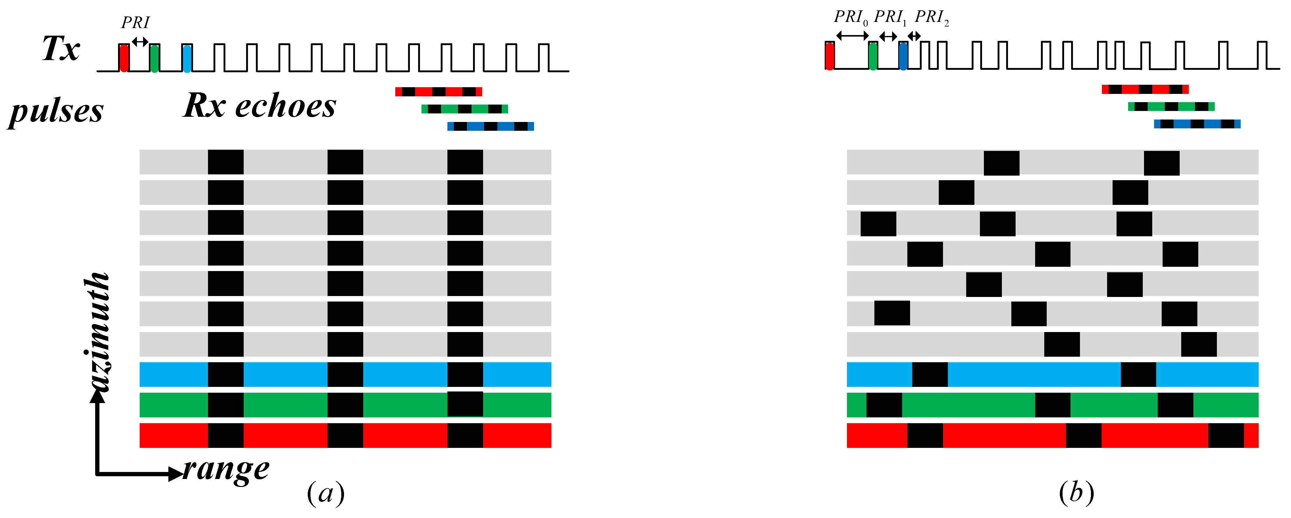
4.1.2. Staggered SAR
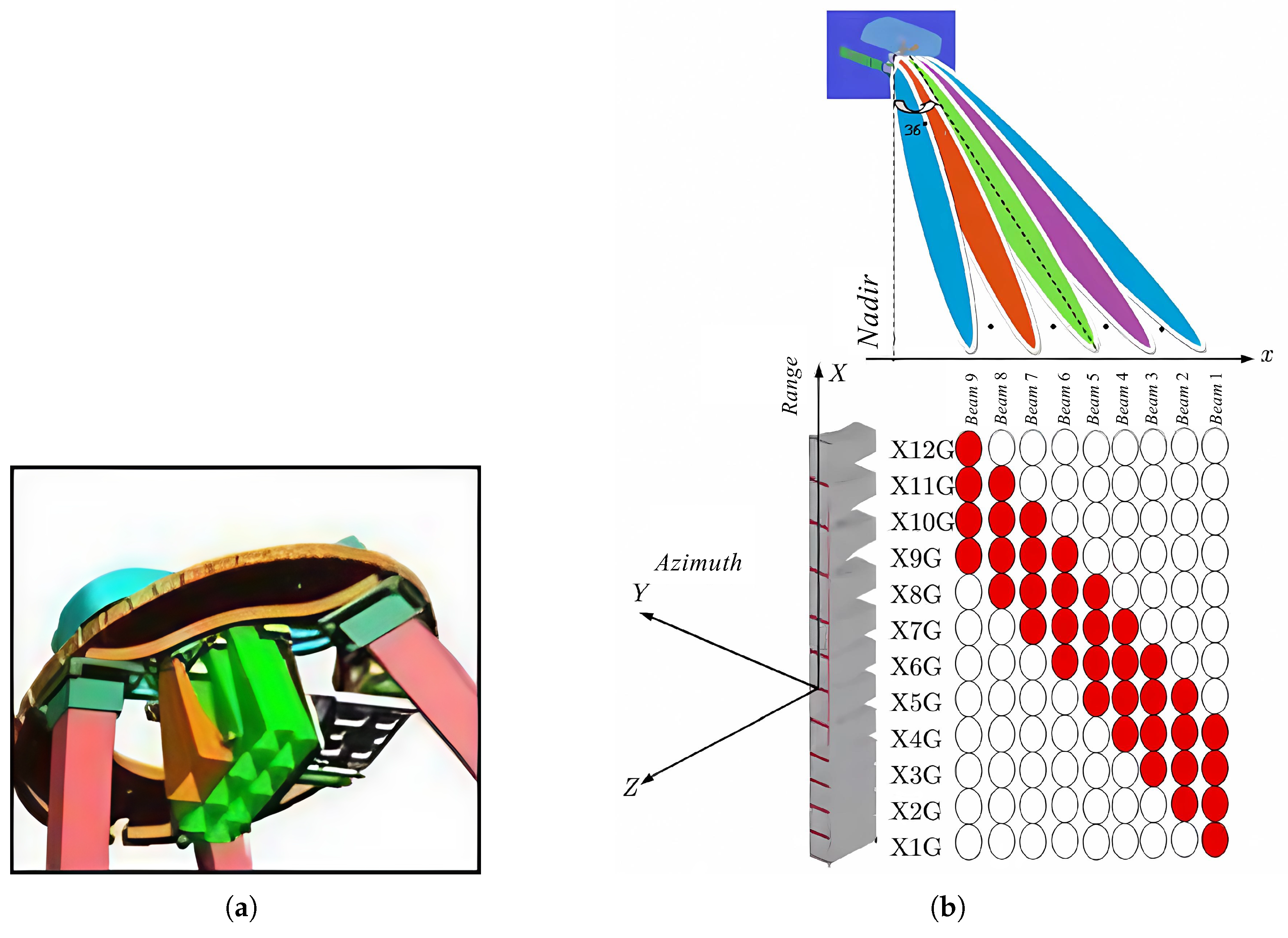
With the adoption of the DBF technique, spaceborne SAR systems can utilize multi-beam techniques in the range direction to achieve simultaneous imaging [73,76,77]. However, using a fixed pulse repetition interval (PRI) introduces blind ranges because the radar cannot receive signals while transmitting, leading to data gaps between adjacent echoes [73].
To address this issue, staggered SAR [78,79,80] continuously varies the PRI, thereby shifting the receive window for each transmitted pulse. Although individual transmissions may still exhibit blind zones, the staggered PRI causes these blind ranges to be distributed across pulses. Over time, this temporal offset effectively eliminates persistent blind regions, as illustrated in Figure 14.
By selecting an optimized PRI sequence, staggered SAR distributes blind ranges across pulses, and interpolation techniques can be applied to reconstruct missing echoes. This approach enables continuous imaging while eliminating blind range artifacts. The staggered PRI technique can be applied to both planar phased arrays and reflector antennas, significantly enhancing SAR system imaging performance, particularly in resolution improvement and blind range reduction.
The integration of reflector antennas in staggered SAR systems offers distinct advantages over phased array architectures. First, the parabolic reflector’s inherent beam-focusing capability simplifies wide-swath illumination by leveraging its large physical aperture, avoiding the need for densely packed T/R modules required in phased arrays. For instance, the Tandem-L mission utilizes a perimeter truss reflector to achieve HRWS imaging with reduced hardware complexity and thermal management demands, as its passive structure eliminates active cooling requirements.
Second, reflector-based systems decouple azimuth and elevation beamforming tasks: azimuth scanning is handled mechanically through staggered PRI, while elevation processing uses digital beamforming (DBF) on the feed array. This separation minimizes real-time computational loads, critical limitations in phased arrays that rely on simultaneous multi-beam steering. Finally, reflectors enable cost-effective scalability for large apertures (e.g., NISAR’s 12 m reflector), whereas phased arrays face prohibitive costs and mass penalties for equivalent performance at the L-band.
Building on these system-level benefits, staggered SARs with reflector antennas also demonstrate strong application potential in future wide-swath and high-resolution missions. For example, staggered SARs combined with full-polarization imaging offer enhanced target characterization capabilities and increased classification accuracy. The technology can mitigate blind zones by continuously varying the pulse repetition interval (PRI), enabling seamless wide-swath imaging at lower data rates. The integration of staggered SAR with DBF is also considered a key enabler for achieving high-resolution, wide-swath SAR.
Despite these promising advantages, implementing staggered SARs with reflector architectures also introduces unique signal processing challenges. The design of the PRI sequence is critical, requiring careful control over its rate and variation. Since the resulting echo data are non-uniformly sampled, reconstruction using interpolation algorithms becomes essential. The choice and accuracy of interpolation techniques can significantly affect the final image quality, adding complexity to the signal processing pipeline. Overall, the combination of staggered PRI and reflector antenna architectures represents a promising direction for scalable, efficient, and high-performance SAR imaging, especially in wide-swath and long-wavelength applications.

4.1.3. SweepSAR

The traditional phased array DBF technique is well suited for short-wavelength SAR systems (e.g., X-band or Ka-band). However, in SARs, the range beamwidth is proportional to wavelength and inversely proportional to antenna height. As wavelength increases, achieving the same beamwidth as short-wavelength systems requires a larger antenna height, significantly increasing the aperture size of phased array antennas. For instance, in [81], an HRWS SAR system operating in the X-band requires a 12 m × 1.66 m receiving antenna. In contrast, an L-band HRWS system would require an antenna of 12 m × 13.3 m—nearly eight times larger than the X-band system. This results in increased data rates, operational complexity, and onboard processing demands.
The SweepSAR technique [82] addresses this issue by combining reflector antennas with one-dimensional phased array feeds, utilizing analog beamforming to enable DBF. Unlike conventional DBF, SweepSAR uses analog beamforming to generate narrow pencil beams in reception while transmitting a wide beam to illuminate the target area.
Operational principle:
(1) Multiple feed elements transmit a wide beam simultaneously.
(2) Only selected feed elements are activated during reception, forming a narrow receive beam, as shown in Figure 15.
This method allows SweepSAR to control the receive beam position via an analog beamforming network, offering advantages over DBF by reducing processing complexity.
Advantages of SweepSAR:
(1) Lower Peak and Average Transmit Power—Reduces power requirements for radar systems.
(2) Wider Swath Coverage.
(3) Lightweight Implementation—Reflector antennas are more mass-efficient than large phased arrays, making them suitable for large-aperture SAR systems.
SweepSAR systems employing reflector antennas demonstrate superior operational flexibility compared to phased arrays. The reflector’s high aperture gain allows for low transmit power while maintaining signal-to-noise ratios, a critical advantage for energy-constrained platforms.
Additionally, the reflector’s fixed geometry simplifies onboard processing: beamforming on receive is performed digitally via the feed array, eliminating the need for real-time phase adjustments across thousands of T/R modules. This architecture also supports lightweight deployable designs (e.g., Capella Space’s perimeter truss antennas), whereas phased arrays suffer from rigidity and stowage limitations for large apertures. These advantages position reflector-based SweepSAR as a scalable solution for next-generation HRWS missions, particularly in long-wavelength bands where phased arrays struggle with aperture size and thermal dissipation.
Due to its advantages in the above aspects, SweepSAR has application potential in many areas. For instance, SweepSAR technology leverages the wide-swath advantages of reflector antennas and is well suited for Earth science missions targeting solid earth, cryosphere, ecosystems, and hydrology. Its application in long-wavelength SAR systems also helps reduce overall system mass.
However, SweepSAR also introduces challenges in signal processing: SweepSAR increases system data rate requirements and requires multiple receiving channels as the number of beams increases. This raises the complexity of both hardware and signal processing, which require further research to overcome.

4.2. Challenges for Reflector Antenna-Based SAR

Despite the potential of reflector antennas in spaceborne SAR applications, several challenges remain in practical implementation:
(1) Limited Beam Steering Accuracy: Compared to phased array antennas, reflector antennas face greater difficulty in achieving precise beam steering. Due to their superior pointing accuracy, phased array antennas remain the preferred choice for many modern SAR systems.
To address this, integrating two-dimensional phased array feeds (PAFs) with reflector antennas is proposed. This configuration combines the high-gain benefits of reflectors with the beamforming flexibility of DBF. By employing digital beamforming in the range direction and multi-channel azimuth processing, the system can achieve dynamic beam synthesis and improved real-time steering accuracy. The SweepSAR technique can further enhance coverage while reducing real-time pointing demands.
(2) Ground Testing Limitations: Simulating a zero-gravity environment on the ground is highly challenging, making it difficult to accurately test the structural deformations and mechanical stress of spaceborne reflector antennas. These uncertainties introduce errors in antenna surface accuracy and structural precision, affecting pointing accuracy and stability.
Future research is directed toward high-accuracy ground simulation techniques and active surface control mechanisms. By incorporating precision shape error modeling, structural dynamics simulations, and closed-loop calibration techniques, the uncertainties in beam pointing and surface accuracy can be reduced. Moreover, active reflector surface control can help compensate for in-orbit deformations.
(3) Structural Complexity and High Precision Requirements: Deployable reflector antennas involve intricate structures that are susceptible to shape errors due to uneven cable tension distribution. Additionally, these antennas often exhibit lower interference resistance, high assembly and calibration complexity, and strict precision requirements for deployment and stowing mechanisms.
To address this, future work should emphasize the development of novel lightweight truss configurations, high-strength reflective materials, and more robust deployment mechanisms. Additionally, modular or segmented reflector architectures, combined with real-time shape monitoring and in-orbit adjustment capabilities, can enhance the reliability and scalability of large deployable antennas.

4.3. Risks for Reflector Antenna-Based SAR

4.3.1. On-Orbit Deployment Accuracy and Structural Stability

The on-orbit deployment process for reflector antennas (especially large deployable reflectors) is highly complex, involving numerous deployment joints and mechanisms (e.g., numerous rods and nodes in framework antennas, rib joints in radial rib antennas). Fully simulating the zero-gravity, thermal cycling, and other space environments on the ground for comprehensive validation is extremely challenging. Post-deployment, the achieved surface accuracy may deviate from the ideal paraboloid (due to thermal distortion, material creep, uneven tension distribution, etc.), leading to focal point deviation (defocusing). This causes antenna pattern degradation, including main beam broadening, gain reduction, and increased sidelobe levels. Ultimately, this manifests in SAR imagery as blurring, ghosting, and other severe quality issues. For instance, the Qilu-1 satellite experienced imaging performance degradation attributed to reflector surface deformation.

4.3.2. High-Power System Failure

Traditionally, reflector antennas rely on single or few high-power feeds (usually hundreds of Watts to kilowatts). Compared to the low-power TR modules of phased array antennas, concentrated high-power feeding poses significant challenges:
(1) Thermal Management Difficulty: Heat dissipation is inefficient in the space vacuum, making high-power feeds and associated beam switching switches (if used) prone to overheating.
(2) Multipactor Discharge: High-power microwave signals in vacuum or low-pressure environments can easily trigger multipactor discharge (secondary electron multiplication) within waveguides, connectors, or switches, leading to permanent component damage or failure. The failure of the HJ-1C satellite was analyzed to be directly related to multipactor damage in its high-power switching components. However, by increasing the pulse repetition frequency and ambiguity suppression in signal processing, usable SAR images were still ultimately obtained.

4.3.3. Risk Mitigation Measures for Future Systems

To address these risks, the future development of reflector antenna-based spaceborne SARs should focus on the following:
(1) Refined Ground Verification: Investing in more advanced ground simulation test facilities (e.g., suspension systems, air-bearing tables) to better replicate the space environment for rigorous testing and validation of deployment mechanism reliability, post-deployment surface accuracy stability under thermal loads, and thermal control performance.
(2) Distributed Feed Architectures: Actively adopting multi-beam feeds or more advanced phased array feed (PAF) technologies (as discussed in Section 3.2.2 and Section 3.2.3 of the manuscript). Distributing the total transmit power across multiple feed elements significantly reduces the power level per channel, thereby fundamentally mitigating thermal stress and multipactor risk (e.g., as planned for the HJ-2-E/F satellites). Furthermore, PAF offers flexible beam control capabilities (as mentioned in Section 4.1.1 DBF and Section 4.1.3 SweepSAR), which can help compensate for potential reflector surface deformations.

4.4. Future Development Directions for Reflector Antenna-Based SAR

Although phased array antennas currently dominate spaceborne SAR applications, reflector antennas offer substantial potential for future development. Key research directions include the following:
(1) HRWS Imaging: Overcoming the fundamental trade-off between resolution and swath width remains a major challenge in spaceborne SAR design. A promising direction involves integrating a two-dimensional PAF with a reflector antenna, combined with range-direction DBF, multi-channel azimuth processing, and the SweepSAR technique to achieve flexible HRWS imaging.
(2) Multi-Mode Imaging Capability: To accommodate diverse observation tasks and enhance system flexibility, next-generation spaceborne SAR systems must support multiple imaging modes. For instance, Israel’s TecSAR supports stripmap, scan, spotlight, and mosaic imaging modes, while the U.S. Capella Space’s Sequoia series offers stripmap, spotlight, and sliding spotlight imaging modes. Developing multi-mode-capable reflector antenna-based SAR systems is a crucial research objective.
(3) Lightweight Design and Novel Deployment Mechanisms: The large size of reflector antennas necessitates deployable structures to meet launch constraints. Future research should focus on novel antenna configurations, advanced deployment mechanisms, improved shape error analysis methods, precision shape optimization, and active surface control techniques. The development of larger reflector antennas imposes stringent requirements on material selection and deployment mechanisms, including truss structures and high-strength reflective mesh materials.
These perspectives indicate that the future of reflector antenna-based SARs will focus on HRWS imaging, multi-mode support, structural innovation, and precision control, further extending spaceborne SARs’ application scope.

5. Conclusions

Reflector antennas offer notable advantages for spaceborne SAR systems, including high gain, lightweight construction, and excellent radiation efficiency, making them well suited for applications in military reconnaissance, environmental monitoring, and commercial remote sensing. This paper has presented the fundamental principles of reflector antennas, examined various structural types, and reviewed commonly used deployable reflector configurations and feed architectures. In addition, this paper surveyed representative spaceborne SAR systems employing reflector antennas and discussed emerging techniques, such as DBF, staggered SAR, and SweepSAR, as well as the technical challenges associated with reflector antenna-based SAR platforms.
To further advance reflector antenna-based SAR systems, future research directions include HRWS imaging, multi-mode SAR functionality, lightweight structural designs, and novel deployment mechanisms. As technological capabilities advance, reflector antennas are expected to play an increasingly critical role in next-generation spaceborne SAR systems, enabling more accurate, efficient, and versatile remote sensing solutions across a broad range of applications.

Author Contributions

Conceptualization, W.Y. and Y.H.; writing—original draft preparation, Y.H.; writing—review and editing, W.Y., Y.H., Q.L., W.L. and Y.F.; supervision, W.Y. and Q.L.; project administration, W.Y.; funding acquisition, W.Y. All authors have read and agreed to the published version of the manuscript.

Funding

This research received no external funding.

Institutional Review Board Statement

Not applicable.

Informed Consent Statement

Not applicable.

Data Availability Statement

No new data were created or analyzed in this study. Data sharing is not applicable to this article.

Conflicts of Interest

The authors declare no conflicts of interest.

References

  1. Wiley, C.A. Synthetic Aperture Radars. IEEE Trans. Aerosp. Electron. Syst. 1985, AES-21, 440–443. [Google Scholar] [CrossRef]
  2. Brown, W.M. Synthetic Aperture Radar. IEEE Trans. Aerosp. Electron. Syst. 1967, AES-3, 217–229. [Google Scholar] [CrossRef]
  3. Moreira, A.; Prats-Iraola, P.; Younis, M.; Krieger, G.; Hajnsek, I.; Papathanassiou, K.P. A Tutorial on Synthetic Aperture Radar. IEEE Geosci. Remote Sens. Mag. 2013, 1, 6–43. [Google Scholar] [CrossRef]
  4. Cumming, I.G.; Wong, F.H. Digital Signal Processing of Synthetic Aperture Radar Data: Algorithms and Implementation; Artech House Publishers: Norwood, MA, USA, 2004. [Google Scholar]
  5. Soumekh, M. Synthetic Aperture Radar Signal Processing; John Wiley & Sons: New York, NY, USA, 1999. [Google Scholar]
  6. Curlander, J.C.; Mcdonough, R.N. Synthetic Aperture Radar: Systems and Signal Processing; John Wiley & Sons: New York, NY, USA, 1991. [Google Scholar]
  7. Reigber, A.; Scheiber, R.; Jager, M.; Prats-Iraola, P.; Hajnsek, I.; Jagdhuber, T.; Papathanassiou, K.P.; Nannini, M.; Aguilera, E.; Baumgartner, S.; et al. Very-High-Resolution Airborne Synthetic Aperture Radar Imaging: Signal Processing and Applications. Proc. IEEE 2013, 101, 759–783. [Google Scholar] [CrossRef]
  8. Bao, Z.; Xing, M.-D.; Wang, T. Radar Imaging Technology: Radar Technology Series; Publishing House of Electronics Industry: Beijing, China, 2005. [Google Scholar]
  9. Balanis, C.A. Antenna Theory: Analysis and Design. IEEE Antennas Propag. Soc. Newsl. 2003, 24, 28–29. [Google Scholar] [CrossRef]
  10. Stutzman, W.L.; Thiele, G.A. Antenna Theory and Design; Wiley: New York, NY, USA, 1998. [Google Scholar] [CrossRef]
  11. Clarricoats, P.; Poulton, G. High-Efficiency Microwave Reflector Antennas—A Review. Proc. IEEE 1977, 65, 1470–1504. [Google Scholar] [CrossRef]
  12. Saunders, R.S.; Spear, A.J.; Allin, P.C.; Austin, R.S.; Berman, A.L.; Chandlee, R.C.; Clark, J.; Decharon, A.V.; De Jong, E.M.; Griffith, D.G.; et al. Magellan Mission Summary. J. Geophys. Res. Planets 1992, 97, 13067–13090. [Google Scholar] [CrossRef]
  13. Castelletti, D.; Farquharson, G.; Stringham, C.; Eddy, D. Operational Readiness of the Capella Space SAR System. In Proceedings of the IGARSS 2020–2020 IEEE International Geoscience and Remote Sensing Symposium, Waikoloa, HI, USA, 26 September–2 October 2020; pp. 3571–3573. [Google Scholar] [CrossRef]
  14. Naftaly, U.; Levy-Nathansohn, R. Overview of the TECSAR Satellite Hardware and Mosaic Mode. IEEE Geosci. Remote Sens. Lett. 2008, 5, 423–426. [Google Scholar] [CrossRef]
  15. Huber, S.; De Almeida, F.Q.; Villano, M.; Younis, M.; Krieger, G.; Moreira, A. Tandem-L: A Technical Perspective on Future Spaceborne SAR Sensors for Earth Observation. IEEE Trans. Geosci. Remote Sens. 2018, 56, 4792–4807. [Google Scholar] [CrossRef]
  16. Kellogg, K.; Hoffman, P.; Standley, S.; Shaffer, S.; Rosen, P.; Edelstein, W.; Dunn, C.; Baker, C.; Barela, P.; Shen, Y.; et al. NASA-ISRO Synthetic Aperture Radar (NISAR) Mission. In Proceedings of the 2020 IEEE Aerospace Conference, Big Sky, MT, USA, 7–14 March 2020; pp. 1–21. [Google Scholar] [CrossRef]
  17. Lange, S. SAR-Lupe satellites launched. Strategie Tech. (Int. Ed.) 2007, 2, 13–15. [Google Scholar]
  18. Yu, W.-D.; Yang, R.L.; Deng, Y.K.; Zhao, F.J.; Lei, H. The Load Design and Implementation of HJ-1-C Space-borne SAR. J. Radars 2014, 3, 256–265. [Google Scholar] [CrossRef]
  19. Farquharson, G.; Castelletti, D.; De, S.; Stringham, C.; Yague, N.; Bes, V.C.; Ryu, J.; Goncharenko, Y. The New Capella Space Satellite Generation: Acadia. In Proceedings of the IGARSS 2023–2023 IEEE International Geoscience and Remote Sensing Symposium, Pasadena, CA, USA, 16–21 July 2023; pp. 1513–1516. [Google Scholar] [CrossRef]
  20. Zhong, S.-S. Antenna Theory and Techniques; Publishing House of Electronics Industry: Beijing, China, 2015. [Google Scholar]
  21. Lo, Y.T.; Lee, S.W. Antenna Handbook: Theory, Applications, and Design; Springer Science & Business Media: Berlin/Heidelberg, Germany, 2013. [Google Scholar]
  22. Lin, Y.-Q. Present and Future of the Spaceborne Synthetic Aperture Radar System. Mod. Radar 2009, 31, 10–13. [Google Scholar]
  23. Sletten, C.J. The Theory of Reflector Antennas; Air Force Cambridge Research Laboratories, Office of Aerospace Research, United States Air Force: Wright-Patterson Air Force Base, OH, USA, 1966. [Google Scholar]
  24. Shafai, L.; Sharma, S.; Balaji, B.; Damini, A.; Haslam, G. Multiple Phase Center Performance of Reflector Antennas Using a Dual Mode Horn. IEEE Trans. Antennas Propag. 2006, 54, 3407–3417. [Google Scholar] [CrossRef]
  25. Pontoppidan, K. GRASP9-Technical Description; Ticra: Copenhagen, Denmark, 2008. [Google Scholar]
  26. Agrawal, P.; Anderson, M.; Card, M. Preliminary Design of Large Reflectors with Flat Facets. IEEE Trans. Antennas Propag. 1981, 29, 688–694. [Google Scholar] [CrossRef]
  27. Li, T. A Study of Spherical Reflectors as Wide-Angle Scanning Antennas. IRE Trans. Antennas Propag. 1959, 7, 223–226. [Google Scholar] [CrossRef]
  28. Rudge, A.; Adatia, N. Offset-Parabolic-Reflector Antennas: A Review. Proc. IEEE 1978, 66, 1592–1618. [Google Scholar] [CrossRef]
  29. Potter, P.D.; Merrick, W.D.; Ludwig, A.C. Big Antenna Systems for Deep-Space Communications. Astronaut. Aeronaut. 1966, 4, 84–95. [Google Scholar]
  30. Zheng, S.-K.; Ji, Y.-Z.; Cui, Z.-Y.; Fang, Y.-G.; Zhou, L.-P. Design and Analysis of HJ-1-C Satellite SAR Antenna. J. Radars 2014, 3, 266–273. [Google Scholar] [CrossRef]
  31. Yuan, J.-J.; Yu, D.-Y. Design and Analysis of Satellite Structures; China Astronautic Publishing House: Beijing, China, 2004. [Google Scholar]
  32. Le Vine, D.; Griffis, A.; Swift, C.; Jackson, T. ESTAR: A Synthetic Aperture Microwave Radiometer for Remote Sensing Applications. Proc. IEEE 1994, 82, 1787–1801. [Google Scholar] [CrossRef]
  33. Wang, L.; Gao, W.-J.; Lei, H.; Liu, X.-M.; Xiong, Y.-H. Analysis for the Pattern of Deployable Truss ReflectorAntenna with Substitute Physical Optics Method. J. Electron. Inf. Technol. 2013, 35, 1484–1489. [Google Scholar] [CrossRef]
  34. Duan, B.-Y. The State-of-the-art and Development Trend of Large Space-borne Deployable Antenna. Electro-Mech. Eng. 2017, 33, 1–14. [Google Scholar] [CrossRef]
  35. Ma, X.-F.; Li, Y.; Xiao, Y.; Zheng, S.-K.; Huang, Z.-R.; Feng, T. Development and Tendency of Large Space Deployable Antenna Reflector. Space Electron. Technol. 2018, 15, 16–26. [Google Scholar]
  36. Wei, J.-F.; Guan, F.-L.; Zhou, L.-P.; Wang, Y.; Liu, T.-L. Design and Analysis of Deployable Parabolic Truss-Mesh Reflector Antenna. Chin. Space Sci. Technol. 2002, 5, 63–68. [Google Scholar]
  37. Hu, F.; Song, Y.-P.; Zheng, S.-K.; Huang, Z.-R.; Zhu, J.L. Advances and Trends in Space Truss Deployable Antennae. J. Astronaut. 2018, 39, 111–120. [Google Scholar]
  38. Zhang, R.-N.; Jiang, X.-P. System Design and In-orbit Verification of the HJ-1-C SAR Satellite. J. Radars 2014, 3, 249–255. [Google Scholar] [CrossRef]
  39. eoPortal. Kondor-FKA 1 Illustration. 2024. Last Updated: 14 August 2024. Available online: https://directory.eoportal.org/satellite-missions/kondor-fka#performance-specifications (accessed on 4 June 2025).
  40. Thomson, M. The AstroMesh Deployable Reflector. In Proceedings of the IEEE Antennas and Propagation Society International Symposium, 1999 Digest, Held in Conjunction with: USNC/URSI National Radio Science Meeting (Cat. No.99CH37010), Orlando, FL, USA,, 11–16 July 1999; Volume 3, pp. 1516–1519. [Google Scholar] [CrossRef]
  41. You, G.-Q. Structual Optimization of Flexible Cable Net Deployable Antenna. Master’s Thesis, Xidian University, Xi’an, China, 2005. [Google Scholar]
  42. Zhou, M.-H. Shape-State Analysis of Hoop Truss Deployable Antenna of Mesh Reflector. Master’s Thesis, Xidian University, Xi’an, China, 2008. [Google Scholar]
  43. Krieger, G.; Hajnsek, I.; Papathanassiou, K.; Eineder, M.; Younis, M.; De Zan, F.; Prats, P.; Huber, S.; Werner, M.; Fiedler, H.; et al. The Tandem-L Mission Proposal: Monitoring Earth’s Dynamics with High Resolution SAR Interferometry. In Proceedings of the 2009 IEEE Radar Conference, Pasadena, CA, USA, 4–8 May 2009; pp. 1–6. [Google Scholar] [CrossRef]
  44. Krieger, G.; Hajnsek, I.; Papathanassiou, K.; Eineder, M.; Younis, M.; Zan, F.D.; Lopez-Dekker, P.; Huber, S.; Werner, M.; Prats, P.; et al. Tandem-L: A Mission for Monitoring Earth System Dynamics with High Resolution SAR Interferometry. In Proceedings of the 8th European Conference on Synthetic Aperture Radar, Aachen, Germany, 7–10 June 2010; pp. 1–4. [Google Scholar]
  45. Krieger, G.; Hajnsek, I.; Papathanassiou, K.; Eineder, M.; Younis, M.; De Zan, F.; Huber, S.; Lopez-Dekker, P.; Prats, P.; Werner, M.; et al. Tandem-L: An Innovative Interferometric and Polarimetric SAR Mission to Monitor Earth System Dynamics with High Resolution. In Proceedings of the 2010 IEEE International Geoscience and Remote Sensing Symposium, Honolulu, HI, USA, 25–30 July 2010; pp. 253–256. [Google Scholar] [CrossRef]
  46. Moreira, A.; Krieger, G.; Younis, M.; Hajnsek, I.; Papathanassiou, K.; Eineder, M.; De Zan, F. Tandem-L: A Mission Proposal for Monitoring Dynamic Earth Processes. In Proceedings of the 2011 IEEE International Geoscience and Remote Sensing Symposium, Vancouver, BC, Canada, 24–29 July 2011; pp. 1385–1388. [Google Scholar] [CrossRef]
  47. Moreira, A.; Krieger, G.; Hajnsek, I.; Papathanassiou, K.; Younis, M.; Lopez-Dekker, P.; Huber, S.; Villano, M.; Pardini, M.; Eineder, M.; et al. Tandem-L: A Highly Innovative Bistatic SAR Mission for Global Observation of Dynamic Processes on the Earth’s Surface. IEEE Geosci. Remote Sens. Mag. 2015, 3, 8–23. [Google Scholar] [CrossRef]
  48. Bachmann, M.; Borla Tridon, D.; De Zan, F.; Krieger, G.; Zink, M. Tandem-L Observation Concept—An Acquisition Scenario for the Global Scientific Mapping Machine. In Proceedings of the EUSAR 2016: 11th European Conference on Synthetic Aperture Radar, Hamburg, Germany, 6–9 June 2016; pp. 1–5. [Google Scholar]
  49. Huber, S.; Villano, M.; Younis, M.; Krieger, G.; Moreira, A.; Grafmueller, B.; Wolters, R. Tandem-L: Design Concepts for a Next-Generation Spaceborne SAR System. In Proceedings of the EUSAR 2016: 11th European Conference on Synthetic Aperture Radar, Hamburg, Germany, 6–9 June 2016; pp. 1–5. [Google Scholar]
  50. Sanjuan-Ferrer, M.J.; Pardini, M.; Borla Tridon, D.; Lopez-Dekker, P.; Papathanassiou, K.; Bachmann, M. Product-Level PerformanceModels for the Tandem-LMission: Forest Structure Case Study. In Proceedings of the EUSAR 2016: 11th European Conference on Synthetic Aperture Radar, Hamburg, Germany, 6–9 June 2016; pp. 1–6. [Google Scholar]
  51. Xaypraseuth, P.; Satish, R.; Chatterjee, A. NISAR Spacecraft Concept Overview: Design Challenges for a Proposed Flagship Dual-Frequency SAR Mission. In Proceedings of the 2015 IEEE Aerospace Conference, Big Sky, MT, USA, 7–14 March 2015; pp. 1–11. [Google Scholar] [CrossRef]
  52. Qi, X. Design and Deployment Dynamics of Ring Truss-Type Deployable Antenna Mechanism; Harbin Institute of Technology: Harbin, China, 2016. [Google Scholar]
  53. eoPortal. Tandem-L Satellite. 2016. Last Updated: 16 September 2016. Available online: https://directory.eoportal.org/satellite-missions/tandem-l#eop-quick-facts-section (accessed on 4 June 2025).
  54. Liu, M.-Z.; Gao, G.F. Advances in the Study on Structure for Space Deployable Antenna. J. Stronautics 2003, 1, 82–87. [Google Scholar]
  55. Li, T.; Ma, X. Technologies of Large Deployable Space Antennas. Space Electron. Technol. 2012, 9, 35–43. [Google Scholar]
  56. Sharay, Y.; Naftaly, U. TECSAR: Design Considerations and Programme Status. IEE Proc.-Radar, Sonar Navig. 2006, 153, 117. [Google Scholar] [CrossRef]
  57. eoPortal. RISAT-2 (Radar Imaging Satellite-2).2023. Last Updated: 10 August 2023. Available online: https://www.eoportal.org/satellite-missions/risat-2#eop-quick-facts-section (accessed on 4 June 2025).
  58. Wang, N.; Lang, Y.; Yu, W.; Ni, J.; Zheng, M. Application of Phased Array Feed Reflector Antenna in Spaceborne SAR. Spacecr. Eng. 2024, 33, 11–17. [Google Scholar]
  59. Lin, C. Antenna Engineering Handbook; Publishing House of Electronics Industry: Beijing, China, 2002. [Google Scholar]
  60. Bahadori, K. Spaceborne Reflector Antennas for Advanced Remote Sensing Applications; University of California: Los Angeles, CA, USA, 2008. [Google Scholar]
  61. Chen, X.; Yu, H.; Wang, X.; Feng, F.; Wang, Z.; Zhang, R.; Liu, S.; Liu, L. Attitude Control Strategy for Multi-aspect Imaging of SAR Satellite with Reflector Antenna System. Spacecr. Eng. 2023, 32, 42–46. [Google Scholar]
  62. Ivashina, M.V.; Iupikov, O.; Maaskant, R.; van Cappellen, W.A.; Oosterloo, T. An Optimal Beamforming Strategy for Wide-Field Surveys With Phased-Array-Fed Reflector Antennas. IEEE Trans. Antennas Propag. 2011, 59, 1864–1875. [Google Scholar] [CrossRef]
  63. Freeman, A.; Johnson, W.; Huneycutt, B.; Jordan, R.; Hensley, S.; Siqueira, P.; Curlander, J. The “Myth” of the Minimum SAR Antenna Area Constraint. IEEE Trans. Geosci. Remote Sens. 2000, 38, 320–324. [Google Scholar] [CrossRef]
  64. Song, R.; Wang, W.; Yu, W. The Latest Developments in Spaceborne High-Resolution Wide-Swath SAR Systems and Imaging Methods. Sensors 2024, 24, 5978. [Google Scholar] [CrossRef]
  65. Gebert, N.; Krieger, G.; Moreira, A. Digital Beamforming on Receive: Techniques and Optimization Strategies for High-Resolution Wide-Swath SAR Imaging. IEEE Trans. Aerosp. Electron. Syst. 2009, 45, 564–592. [Google Scholar] [CrossRef]
  66. Kare, J.T. Moving Receive Beam Method and Apparatus for Synthetic Aperture Radar. US Patent 6,175,326, 23 January 2001. Assignee: Regents of University of California: Oakland, CA, USA; DOE Contract Number: W-7405-ENG-48. Available online: https://patents.google.com/patent/US6175326B1/en (accessed on 4 June 2025).
  67. Süß, M.; Grafmüller, B.; Zahn, R. A Novel High Resolution, Wide Swath SAR System. In Proceedings of the IGARSS 2001. Scanning the Present and Resolving the Future. Proceedings. IEEE 2001 International Geoscience and Remote Sensing Symposium, Sydney, NSW, Australia, 9–13 July 2001; (Cat. No. 01CH37217). IEEE: New York, NY, USA, 2001; Volume 3, pp. 1013–1015. [Google Scholar]
  68. Suess, M.; Wiesbeck, W. Side-Looking Synthetic Aperture Radar System. Eur. Pat. EP 2002, 1, 487. [Google Scholar]
  69. Younis, M.; Huber, S.; Patyuchenko, A.; Bordoni, F.; Krieger, G. Performance Comparison of Reflector- and Planar-Antenna Based Digital Beam-Forming SAR. Int. J. Antennas Propag. 2009, 2009, 1–13. [Google Scholar] [CrossRef]
  70. Huber, S.; Younis, M.; Patyuchenko, A.; Krieger, G.; Moreira, A. Spaceborne Reflector SAR Systems with Digital Beamforming. IEEE Trans. Aerosp. Electron. Syst. 2012, 48, 3473–3493. [Google Scholar] [CrossRef]
  71. Younis, M.; De Almeida, F.Q.; Villano, M.; Huber, S.; Krieger, G.; Moreira, A. Digital Beamforming for Spaceborne Reflector-Based Synthetic Aperture Radar, Part 1: Basic Imaging Modes. IEEE Geosci. Remote Sens. Mag. 2021, 9, 8–25. [Google Scholar] [CrossRef]
  72. Younis, M.; Huber, S.; Patyuchenko, A.; Bordoni, F.; Krieger, G. Digital beam-forming for spaceborne reflector- and planar-antenna SAR — A system performance comparison. In Proceedings of the 2009 IEEE International Geoscience and Remote Sensing Symposium, Cape Town, South Africa, 12–17 July 2009; Volume 3, pp. III-733–III-736. [Google Scholar] [CrossRef]
  73. Krieger, G.; Gebert, N.; Younis, M.; Bordoni, F.; Patyuchenko, A.; Moreira, A. Advanced Concepts for Ultra-Wide-Swath SAR Imaging. In Proceedings of the 7th European Conference on Synthetic Aperture Radar, Friedrichshafen, Germany, 2–5 June 2008; pp. 1–4. [Google Scholar]
  74. Huber, S. Spaceborne SAR Systems with Digital Beamforming and Reflector Antenna Deutsches Zentrum für Luft- und Raumfahrt (DLR), Cologne, Germany, 2014. Available online: https://elib.dlr.de/93190/ (accessed on 4 June 2025).
  75. Huber, S.; Younis, M.; Krieger, G.; Moreira, A. Advanced Spaceborne SAR Systems with Array-Fed Reflector Antennas. In Proceedings of the 2015 IEEE Radar Conference (RadarCon), Arlington, VA, USA, 10–15 May 2015; pp. 0253–0258. [Google Scholar] [CrossRef]
  76. Krieger, G.; Gebert, N.; Younis, M.; Moreira, A. Advanced Synthetic Aperture Radar Based on Digital Beamforming and Waveform Diversity. In Proceedings of the 2008 IEEE Radar Conference, Rome, Italy, 26–30 May 2008; pp. 1–6. [Google Scholar] [CrossRef]
  77. Krieger, G.; Younis, M.; Huber, S.; Bordoni, F.; Patyuchenko, A.; Kim, J.; Laskowski, P.; Villano, M.; Rommel, T.; Lopez-Dekker, P.; et al. Digital Beamforming and MIMO SAR: Review and New Concepts. In Proceedings of the EUSAR 2012, 9th European Conference on Synthetic Aperture Radar, Nuremberg, Germany, 23–26 April 2012; pp. 11–14. [Google Scholar]
  78. Villano, M.; Krieger, G.; Moreira, A. Staggered SAR: High-Resolution Wide-Swath Imaging by Continuous PRI Variation. IEEE Trans. Geosci. Remote Sens. 2014, 52, 4462–4479. [Google Scholar] [CrossRef]
  79. Villano, M.; Krieger, G.; Moreira, A. A Novel Processing Strategy for Staggered SAR. IEEE Geosci. Remote Sens. Lett. 2014, 11, 1891–1895. [Google Scholar] [CrossRef]
  80. Villano, M. Staggered Synthetic Aperture Radar; DLR, Deutsches Zentrum für Luft-und Raumfahrt: Stuttgart, Germany, 2016. [Google Scholar]
  81. Heer, C.; Shutie, P. Digital Beam Forming Synthetic Aperture Radar. In Proceedings of the IEEE MTT-S International Microwave Symposium Digest, Long Beach, CA, USA, 17 June 2005; pp. 1627–1630. [Google Scholar] [CrossRef]
  82. Freeman, A.; Krieger, G.; Rosen, P.; Younis, M.; Johnson, W.T.K.; Huber, S.; Jordan, R.; Moreira, A. SweepSAR: Beam-forming on Receive Using a Reflector-Phased Array Feed Combination for Spaceborne SAR. In Proceedings of the 2009 IEEE Radar Conference, Pasadena, CA, USA, 4–8 May 2009; pp. 1–9. [Google Scholar] [CrossRef]
Figure 1. Structural schematic of a parabolic reflector antenna (feed placed at the focus).
Remotesensing 17 02432 g001
Figure 2. Offset parabolic reflector antenna structure.
Remotesensing 17 02432 g002
Figure 3. Parabolic cylindrical reflector antenna: (a) basic configuration; (b) beam direction.
Remotesensing 17 02432 g003
Figure 4. (a) Schematic diagram of elliptical reflector antenna; (b) position of phased array feed.
Remotesensing 17 02432 g004
Figure 5. Dual-reflector antennas: (a) Cassegrain antenna; (b) equivalent feed method principle.
Remotesensing 17 02432 g005
Figure 6. Deployable antenna of HJ-1-C [30]: (a) on-orbit folded state; (b) on-orbit deployed state.
Remotesensing 17 02432 g006
Figure 7. Framework deployable antenna: (a) HJ-1-C [38]; (b) Kondor-FKA 1 illustration [39].
Remotesensing 17 02432 g007
Figure 9. (a) Radial rib deployable antenna [35]; (b) TecSAR antenna [14].
Remotesensing 17 02432 g009
Figure 10. Single-beam feed: (a) Qilu-1; (b) Capella Acadia SAR satellite [19].
Remotesensing 17 02432 g010
Figure 11. Multi-beam feeds: (a) RISAT-2 [57]; (b) HJ-1-C [30].
Remotesensing 17 02432 g011
Figure 12. Phased array feed reflector antenna basic configuration.
Remotesensing 17 02432 g012
Figure 13. Reflector antenna with DBF: (a) reflector antenna-based SAR system with DBF; (b) wide-transmit, narrow-receive configuration.
Remotesensing 17 02432 g013
Figure 14. Blind range locations: (a) fixed PRI SAR, (b) staggered SAR.
Remotesensing 17 02432 g014
Figure 15. SweepSAR operational diagram.
Remotesensing 17 02432 g015
Table 1. Basic classification and spaceborne SAR applications of reflector antennas.
Reflector Antenna TypesCharacteristicsRepresentative Spaceborne SAR Systems
Parabolic Reflector AntennaHigh gain, narrow beam, strong directivity, simple structureLacrosse, Magellan, SAR-Lupe, HJ-1-C, Qilu-1, Acadia, Neptune-01, TecSAR, RISAT-2
Parabolic Cylindrical Reflector AntennaLine source feed, suitable for wide-angle scanning-
Elliptical Reflector AntennaDual-focus design, flexible beam controlHJ-2-E/F
Dual-Reflector AntennaTwo-reflector system, compact feed placement, low feedline lossQPS-SAR
Spherical Reflector AntennaSpherical surface, suitable for wide-angle coverage-
Table 2. Summary of deployable antenna type classification.
Deployable Antenna TypeCharacteristicsSpaceborne SAR Applications
Framework-BasedHigh deployment stiffness, excellent thermal stability, scalable modular assembly, precise surface control, but heavier structureHJ-1-C (China, 2012), Qilu-1 (China, 2021), Kondor-FKA No.2 (Russia, 2024)
Perimeter Truss-BasedHigh deployment ratio, simplified structure, lightweight designAcadia (USA, 2023), Tandem-L (Germany), NISAR (USA, India), EOS SAR (USA)
Radial Rib-BasedSimple structure, reliable deployment, high stiffnessTecSAR (Israel, 2008), RISAT-2 (India, 2009), QPS-SAR (Japan, 2019), Umbra (USA, 2021), Neptune-01 (China, 2024)
Table 3. Summary of reflector antenna feed forms.
Feed TypeCharacteristicsSpaceborne SAR Applications
Single-Beam FeedSimple design, cost-effectiveQilu-1 (China, 2021)
Multi-Beam FeedsEnables beam scanning and reconfiguration, but with limited and discontinuous scanning anglesTecSAR (Israel, 2008), RISAT-2 (India, 2009), HJ-1-C (China, 2012)
Phased Array Feed (PAF)Provides larger scanning angles, continuous beam steering, and higher flexibility and reliability than multi-beam feedsHJ-2-E/F (China)
Table 4. Summary of reflector antenna configurations in representative SAR systems.
SAR System (Country, Year)Feed TypeReflector Structure TypeSystem Characteristics
SAR-Lupe (Germany, 2006–2008)Single-Beam FeedRigid Reflector antennaCompact rigid antenna, military imaging
TECSAR (Israel, 2008)Multi-Beam FeedsRadial Rib Deployable AntennaLightweight deployable reflector, 3.6 m aperture
RISAT-2 (India, 2009)Multi-Beam FeedsRadial Rib Deployable Antenna3.6 m diameter mesh reflector, all-weather surveillance
HJ-1-C (China, 2012)Multi-Beam FeedsFramework Deployable AntennaDual-polarized X-band SAR, multi-mode operation
QPS-SAR (Japan, 2019)Single-Beam FeedDual-Reflector Antenna3.6 m deployable reflector, lightweight small satellite SAR
Qilu-1 (China, 2021)Single-Beam FeedFramework Deployable AntennaKu-band, high-resolution lightweight SAR, total weight 50 kg
Acadia (USA, 2023)Single-Beam FeedPerimeter Truss Deployable Antenna8 m2 reflector, high revisit rate, commercial small satellite
HJ-2-E/F (China, upcoming)Phased Array FeedFramework Deployable AntennaWorld’s first SAR system with phased array feed and reflector antenna
Tandem-L (Germany, upcoming)Multi-Beam FeedsPerimeter Truss Deployable AntennaDBF-based reflector SAR, used for deformation and biomass monitoring
NISAR (India/USA, upcoming)Multi-Beam FeedsPerimeter Truss Deployable AntennaDual-frequency (L/S-band), 12 m deployable mesh, wide-swath InSAR
Disclaimer/Publisher’s Note: The statements, opinions and data contained in all publications are solely those of the individual author(s) and contributor(s) and not of MDPI and/or the editor(s). MDPI and/or the editor(s) disclaim responsibility for any injury to people or property resulting from any ideas, methods, instructions or products referred to in the content.

