Article

Mainlobe Jamming Suppression via Joint Polarization-Range-Doppler Processing

by
Liyuan Wang
,
Huafeng He
*,
Zhen Li
,
Buma Xiao
and
Tao Zhou
College of Missile Engineering, Rocket Force Engineering University, Xi’an 710025, China
*
Author to whom correspondence should be addressed.
Remote Sens. 2025, 17(12), 1995; https://doi.org/10.3390/rs17121995
Submission received: 7 April 2025 / Revised: 30 May 2025 / Accepted: 6 June 2025 / Published: 9 June 2025

Abstract

In the field of electromagnetic countermeasures, suppressing mainlobe jamming represents a critical challenge requiring urgent resolution. Conventional polarization-based anti-jamming techniques, which fundamentally rely on obtaining pure jamming signals for prior parameter estimation, demonstrate limited effectiveness against co-frequency mainlobe suppression jamming. To tackle this problem, this paper proposes an innovative joint polarization-range-Doppler processing framework for airborne dual-polarized radar systems. Initially, we develop a polarized eigen-element surrogate technique to accurately estimate jamming polarization parameters, which demonstrates robust performance even under low jamming-to-signal ratio conditions. Subsequently, through Doppler compensation and range processing, we establish a combined feature projection method capable of reliably estimating target polarization from mixed signals containing target echoes, jamming, and noise. Then, leveraging the obtained polarization information, we construct an optimal target polarization projection filter. To comprehensively evaluate system performance, we introduce the novel metric of signal loss ratio, enabling rigorous analysis of the filter’s operational boundaries from dual perspectives: jamming suppression capability and target signal preservation. Extensive simulations across six distinct operational scenarios conclusively demonstrate the method’s superior performance, confirming its significant potential for practical implementation in engineering applications.

1. Introduction

In modern electronic warfare, deliberate jamming has emerged as a prevalent and highly effective countermeasure, posing significant challenges to radar target detection and identification. While radar anti-jamming techniques have achieved substantial progress in the temporal, spectral, and spatial domains [1,2,3,4,5], the rapid evolution of electronic warfare systems toward high-intensity, broadband, and multi-modal capabilities has introduced new complexities. Contemporary advanced jamming systems can now rapidly identify radar transmission characteristics and subsequently generate agile noise or composite noise jamming within the main lobe. This sophisticated jamming modality substantially reduces the discriminability between radar targets and jamming signals across conventional domains, thereby diminishing the effectiveness of traditional countermeasures, including pulse integration, sidelobe blanking, and adaptive beamforming [6]. The seminal theoretical frameworks established by Sinclair [7], Kennaugh [8], Huynen [9], and Boerner [10], have fundamentally advanced radar signal processing by introducing polarization as a critical additional dimension. This theoretical foundation has led to the paradigm of multi-domain information fusion, where polarization characteristics are synergistically combined with other signal attributes. Such multidimensional processing has become indispensable for addressing the critical challenge of mainlobe jamming suppression in modern radar systems.

1.1. Research on Polarization-Based Anti-Jamming

Polarization anti-jamming exploits the antenna’s selectivity to different polarization signals, thereby attenuating jamming and enhancing signal quality. Typically, the filter design process requires prior acquisition of both target and jamming polarization information. Subspace-based parametric estimation methods serve as effective means for extracting signal polarization characteristics. In 1993, Li [11] pioneered the application of the estimation of signal parameters via rotational invariance techniques in polarization-sensitive arrays (PESPRTT), enabling joint estimation of both the direction of arrival (DOA) and polarization parameters. Expanding on this foundational work, subsequent studies investigated diverse array configurations [12,13] and the coherence of signal sources [14]. Reference [15] employed the vector cross-product operator to decouple angle and polarization parameters, developing a reduced-dimension MUSIC algorithm for polarization estimation (PMUSIC). Further advancing this approach, Reference [16] proposed the Root-MUSIC method through closed-form solutions, significantly reducing computational complexity. Addressing the challenging issue of extracting target signal polarization in mixed clutter and jamming environments, Reference [17] established a target discrimination criterion using the generalized likelihood ratio. By optimizing the transmit polarization to enhance the system response matrix, it significantly improves the target discrimination probability in clutter. Reference [18] proposes a slant projection DOA estimation algorithm based on spatial polarization characteristics. Employing an asynchronous estimation approach, this method effectively enhances the ability to distinguish dense signals. For pulse-to-pulse variable polarization jamming suppression, Reference [19] utilized pulse compression peak sidelobe ratio as a polarization invariant, implementing virtual polarization adaptation (VPA) for strong jammer polarization estimation. When desired signals outnumber sensors, References [20,21,22,23] employ nested arrays or coprime arrays to increase degrees of freedom (DOFs), achieving satisfactory performance. In summary, the above references exhibit two notable characteristics. First, certain specific prior features are leveraged to facilitate the relevant processing in [15,16,17,19]. Second, the advantage of array DOFs is fully utilized to estimate polarization parameters in [12,15,19,20,21,22,23].
Backed by polarization information, significant academic and practical advances have been achieved in jamming polarization suppression. Nathanson [24] first proposed a closed-loop adaptive polarization filter, which employs an “asynchronous” iterative approach to compute the optimal weight coefficients for achieving jamming cancellation. Due to its simple architecture and inherent compensation for polarization channel imbalances, this method has been widely deployed on airborne radar platforms. In scenarios where target polarization and jamming polarization are not orthogonal, Reference [25] introduced the zero-phase-shift instantaneous polarization filter, utilizing linear transformations and amplitude-phase compensation to effectively nullify jamming. References [26,27] incorporated the mathematical tool of oblique projection to propose the oblique projection polarization filter. This innovative approach circumvents the issue of target signal suppression that often accompanies jamming suppression, thereby enhancing the overall effectiveness of the filtering process. Reference [28] proposes a polarization and frequency diverse MIMO radar that adjusts the transmit polarization based on the signal-to-interference-plus-noise ratio (SINR) optimization criterion and leverages the spatial characteristics of MIMO to suppress mainlobe jamming. Reference [29] generated a synthesized transmit beam with spatially varying polarization to disrupt the 180° phase shift in the jammer’s transformation loop, thereby significantly degrading the performance of broadside jammers. Reference [30] designed a spatial multi-notch virtual polarization filter, eliminating the impact of elevation angle measurement errors on jamming suppression performance. Reference [31] introduces an anti-jamming method based on the generalized slant projection transform (GSPT). This method performs multi-pulse slant projection operations and incorporates a similarity criterion to reject anomalous pulses, thereby effectively suppressing variable-polarization mainlobe jamming during coherent integration. These approaches share a common framework: deriving optimal weights through specific criteria (target/jamming polarization characteristics) followed by polarization filtering. Overall, existing polarization filters can be categorized into three types: first, jamming suppression filters that minimize jamming power [24,30,32,33]; second, target-matching filters that maximize target power [25,26,27,31]; and third, SINR filters that maximize the signal-to-interference-plus-noise ratio [28,34,35,36].

1.2. Innovative Points of This Paper

In general, polarization-based jamming suppression relies on prior polarization characteristics. However, in strong jamming environments, i.e., the jamming power significantly exceeds the target echo power, accurate polarization feature extraction becomes considerably challenging. Moreover, existing polarization filtering methods lack comprehensive analysis and quantitative evaluation of target signal loss. To overcome these limitations, this paper proposes a joint polarization-range-Doppler filtering method for dual-polarized radar systems. It can accurately extract the polarization features of targets and jamming from mixed signals, effectively suppress mainlobe jamming, and fully restore the target signal. The main innovations of this paper are as follows:
  • We propose a polarized eigen-element surrogate method (PEES) to estimate jamming polarization. The method enhances the distinguishability between jamming and target signatures through joint time-polarization domain processing. Unlike methods in References [11,19], the proposed method maintains robust estimation accuracy under low jamming-to-signal ratio (JSR) conditions while demonstrating superior computational efficiency compared to References [15,19].
  • For the challenging task of target polarization extraction from mixed echoes containing a target, jamming, and noise, this paper proposes a combined feature projection method (CFP) based on phase compensation and coherent accumulation. Compared with the feature projection approach (FP), the proposed method maintains superior performance even in strong jamming environments.
  • We design a target polarization projection filter (TPPF) that optimizes the output SINR through noise-constrained processing. Furthermore, we introduce the concept of the signal loss ratio (SLR) metric, and the filter’s performance is comprehensively assessed in terms of both jamming suppression capability and target signal loss.
  • Leveraging the aforementioned steps, a method for suppressing mainlobe jamming through joint polarization-range-Doppler processing is constructed, and its effectiveness is verified through six sets of simulation cases.
The rest of the article is organized as follows. Section 2 proposes the PEES for estimating the jamming polarization state; Section 3 introduces the CFP for extracting target polarization features; Section 4 designs the TPPF and analyzes its performance; Section 5 conducts numerical simulations; Section 6 summarizes this paper.

1.3. Notation

In this article, we use italics for variables x, lowercase boldface for vectors x , and uppercase boldface for matrices X . The notations ∗, ⊙, H , and represent a convolution, Hadamard product, and Hermitian and generalized inverse, respectively. The notations arg and denote the phase and amplitude of a complex number. The operators 2 and F denote the 2-norm and F-norm of a vector. norm and F represent the normalization and Fast Fourier Transform operations. Finally, O represents the complexity notation.

2. Polarization State Estimation of Jamming

2.1. Signal Polarization Reception Model

Assume that the antenna’s transmit polarization is horizontal (the same applies to vertical polarization), and the receiver is dual-polarized with both horizontal and vertical components. The transmitted waveform is a linear frequency-modulated (LFM) signal, which can be expressed as
s T ( t ) = rect t τ T exp j 2 π f 0 t + 1 2 K t 2 ,
where rect is the gate function; τ T is the pulse width of the transmitted signal; f 0 is the carrier frequency of the signal and K is the chirp rate of the LFM.
Now, let the target scattering matrix be S , and the jammer on the target platform radiates co-frequency mainlobe jamming. So, the response voltages of the radar receiver’s dual-polarization channels can be expressed as
v ( t ) = h r S h t s T ( t ) + h r h J s J ( t ) + n ( t ) ,
where h t = 1 0 T is the transmit polarization and h r = I 2 is the receive polarization vector. h J = cos γ J sin γ J exp ( j η J ) T is the jamming polarization. Here, γ J and η J represent the auxiliary polarization angle and polarization phase difference of the jamming, respectively. s T ( t ) and s J ( t ) represent the echoes from the target and jamming. n ( t ) is Gaussian white noise with a mean of zero and a variance of σ N 2 .
After down-conversion processing, the baseband data can be expressed as
v base ( t ) = v H base ( t ) v V base ( t ) = S hh s T base ( t ) + cos γ J s J base ( t ) + n 1 H ( t ) S vh s T base ( t ) + sin γ J exp ( j η J ) s J base ( t ) + n 1 V ( t ) ,
where S p q is the element of the polarization scattering matrix, which denotes the p-polarized component of the backscattered wave from the target when illuminated by q-polarized radiation, where the subscripts p , q H , V denote the horizontal and vertical polarization components, respectively. S hh S vh T characterizes the target’s polarization under horizontal polarization transmission and can be represented by h T .
h T = S h t = S hh 2 + S vh 2 S hh S hh 2 + S vh 2 S vh S hh 2 + S vh 2 cos γ T sin γ T exp ( j η T ) ,
where S hh 2 + S vh 2 is a constant and does not affect the target’s polarization. Thus, γ T , η T alone fully characterizes the target’s polarization state.

2.2. Polarized Eigen-Element Surrogate

We aim to distinguish the polarization of jamming through single-pulse processing. When the jamming power is much larger than the signal echo, i.e., under high JSR conditions, v base ( t ) can be divided into the jamming subspace u J and the noise subspace u N , as shown in Equation (5).
v base ( t ) = h J s J base ( t ) u J + h T s T base ( t ) + n 1 ( t ) u N ,
Note that u N includes the target echo and noise. When the jamming power is comparable to the signal echo, the influence of the noise subspace on the jamming subspace is significant and cannot be ignored. To mitigate the impact of the noise subspace on the jamming signal subspace, we utilize polarization invariance to perform time-domain filtering.
Property 1.
When identical signal processing operations are applied to the received signals across all polarization channels, the polarization parameters are preserved.
Using the above property, the matched filtering function is formulated as
h ( t ) = rect t τ T exp j π K t 2 ,
Performing matched filtering on the baseband data using Equation (6) yields
v PC ( t ) = v base ( t ) h ( t ) = h J s J PC ( t ) + h T s T PC ( t ) + n 2 ( t ) ,
where ∗ denotes the convolution operation, and n 2 ( t ) denotes the noise vector after matched filtering. Pulse compression enhances the SNR but does not effectively increase the jamming power, due to the lack of correlation between the jamming and the target echo.
In the jamming-dominated subspace, target power amplification is undesirable. To achieve effective subspace discrimination, we formulate a time-domain limiter function based on the following criteria g ( t ) :
g ( t ) = norm 1 sinc ( ρ B t ) ,
where B = K τ T is the bandwidth; ρ is the frequency expansion factor, which improves the filtering performance by adjusting the mainlobe width, and here ρ = 1 ; norm is the normalization function. After time-domain filtering, we can obtain
v TF ( t ) = v PC ( t ) g ( t ) = h J s J TF ( t ) + h T s T TF ( t ) + n 3 ( t ) ,
where ⊙ denotes the Hadamard product.
After the above steps, the jamming and noise subspaces are effectively separated. Thus, Equation (9) can be approximated as
v TF ( t ) = h J s J TF ( t ) + u N ( t ) ,
here, u N ( t ) = h T s T TF ( t ) + n 3 ( t ) .
On this basis, we can calculate the Polarization Coherence Matrix (PCM) of v TF ( t ) and obtain
R v = v TF ( t ) v TF ( t ) H N r ,
where N r is the number of fast-time domain samples; ( ) H is the conjugate transpose. When the jamming and noise subspaces are uncorrelated, Equation (11) is equivalent to
R v = 1 N r σ J 2 h J h J H + u N u N H ,
where σ J 2 is the power of jamming.
Theorem 1.
For a unit polarization vector h , its polarization coherence matrix is defined as R = h h H . The eigenvector U 1 corresponding to the principal eigenvalue of R shares the same polarization direction as h and satisfies the equation h = μ U 1 , where μ is a complex constant with a modulus of 1.
Proof of Theorem 1.
The eigenvalue decomposition of R yields
RU = U Λ ,
where Λ is the eigenvalue of R , satisfying Λ = diag ( λ 1 , λ 2 ) and here λ 1 > λ 2 ; U is the corresponding eigenvector. Since rank ( R ) = 1 , we can obtain λ 1 = 1 and λ 2 = 0 . Therefore, the matrix R and the principal eigenvector U 1 have the following relationship:
h h H U 1 = U 1 ,
where h H U 1 is a scalar, denoted as μ . Therefore, Equation (14) is equivalent to
h = μ U 1 ,
Thus, the proof of Theorem 1 is completed. It reveals the correspondence between the eigenvector and the desired signal’s polarization vector, leveraging the amplitude and phase differences in the dual-polarization channel signals.
Now, we substitute Equation (15) into Equation (12). Ideally, ignoring the effect of the error term u N u N H , we have
σ J 2 N r h J = μ U 1 ,
Therefore, the polarization parameters of the jamming can be obtained by
γ ^ J = tan 1 U 1 V U 1 H η ^ J = arg U 1 V U 1 H ,
It is worth noting that the error term u N u N H significantly impacts estimation accuracy. Through pulse compression and time-domain filtering, the proposed method effectively reduces its influence, achieving stronger robustness under low SNR and ISR conditions. In summary, the PEES includes the following steps:
Step 1: 
Construct h ( t ) via Equation (6) and obtain v PC ( t ) through matched filtering using Equation (6).
Step 2: 
Construct the time-domain limiter g ( t ) via Equation (8), and filter v PC ( t ) using Equation (9).
Step 3: 
Plug the filtering result into Equation (11) to compute the PCM R v .
Step 4: 
Perform eigenvalue decomposition on R v to get the principal eigenvector U 1 , and estimate the jamming’s polarization parameters via Equation (17).

3. Polarization Feature Extraction of Target

After obtaining the jamming polarization, References [24,25] suppress jamming through polarization cancellation and orthogonal projection filtering. The main principle is to construct an orthogonal projection space E h J using the polarization vector h J , viz.,
E h J = I h J h J h J ,
where I h J is the identity matrix with the same row dimension as h J ; x represents the generalized inverse of vector x , satisfying x = x H x 1 x H .
Directly applying the projection operator E h J to the signal echo can eliminate the jamming, as demonstrated below:
E h J v PC ( t ) = E h J h J s J PC ( t ) + h T s T PC ( t ) + n 2 ( t ) = E h J h T s T PC ( t ) + E h J n 2 ( t ) ,
However, the aforementioned methods exhibit two principal limitations that warrant careful consideration. First, while effectively suppressing jamming signals, these techniques inevitably introduce target echo attenuation and may inadvertently amplify noise components. Second, the phase relationships between different polarization channels are altered after projection, which disrupts the target’s polarization information and negatively impacts subsequent target polarization identification. These issues can be addressed by constructing the projection matrix based on the polarization information of both the jamming and the target [31].
Thus, this section is dedicated to extracting the target’s polarization features and overcoming two critical challenges as follows:
(1)
Estimating the target’s polarization parameters in the underdetermined case (limited by dual-polarization antenna DOF, typically only one desired signal can be estimated).
(2)
Accurate extraction of polarization characteristics from target signals in suppression jamming environments.
To this end, we propose the combined feature projection (CFP) method to address these challenges.

3.1. Feature Projection

After obtaining the jamming polarization parameters, the equivalent polarization vector for suppressing jamming is
h ^ J = cos γ ^ J sin γ ^ J exp η ^ J ,
Then, we project the PCM of the pulse-compressed signal v PC ( t ) onto the jamming’s orthogonal space E h J to get the feature projection matrix R 0 , viz.,
R 0 = E h J E v PC v PC H ,
When the target, jamming, and noise are uncorrelated, Equation (21) can be simplified as
R 0 = σ T 2 E h J h T h T H + σ N 2 E h J ,
where σ T 2 and σ N 2 denote the powers of the target and noise. Subsequently, we compute the gram matrix of R 0 , that is,
R T = R 0 H R 0 = β h T h T H + σ N 4 E h J ,
where β = σ T 4 h T H E h J h T is a constant. Performing eigenvalue decomposition on R T yields the eigenvector corresponding to the principal eigenvalue V 1 . In conjunction with Theorem 1, the polarization parameters of the target can be obtained, viz.,
γ ^ T = tan 1 V 1 V V 1 H η ^ T = arg V 1 V V 1 H ,
This method typically requires two conditions: (1) the target, jamming, and noise need to be uncorrelated; (2) the jamming signal power should be kept moderate.
However, under strong jamming conditions, i.e., σ J 2 σ T 2 , the error introduced by the cross-terms of the PCM becomes non-negligible. Moreover, after orthogonal projection, the noise characteristics change, possibly increasing the noise component and affecting the accuracy of target polarization parameter estimation.
In a nutshell, when the aforementioned two conditions are not fully satisfied, R 0 should be revised to
R 0 = σ T 2 E h J h T h T H u T + σ JT E h J h T h J H + σ N 2 E h J u N ,
where σ JT = s J PC s T PC H ; σ JT E h J h T h J H is the cross-term jamming.

3.2. Coherent Integration Under Jamming

To facilitate the extraction of target polarization features using the feature projection (FP) method, we incorporate coherent integration technology. It involves adding multiple coherent echo signals together to enhance the energy of the target signal while suppressing noise. The synergy between FP and coherent integration gives rise to a combined feature projection (CFP) method. The details of CFP are as follows.
(1) 
Radial Velocity Estimation
Assuming the radar is mounted on a moving platform with a pulse accumulation number of M, and within a coherent processing interval (CPI), the platform moves towards the target at a radial velocity v. Then, the m-th mixed pulse-compressed signal can be expressed as
v ( m ) PC ( t ) = h T s T ( m ) PC ( t ) + h J s J ( m ) PC ( t ) + n 2 ( m ) ( t ) ,
where s T ( m ) PC ( t ) is written as
s T ( m ) PC ( t ) = A T τ T exp j 2 π f 0 τ m sinc K τ T ( t τ m ) ,
where A T is the signal amplitude; f 0 is the carrier frequency; τ m is the time delay of the m-th pulse, determined by the radar–target radial distance and can be expressed as
τ m = 2 R m c = 2 ( R 0 + v t m ) c ,
where R 0 is the initial radial distance between radar and target; c is the speed of light; t m = m T r is the slow-time variable, and here, m denotes the pulse index; T r is the pulse repetition interval. Substituting Equation (28) into Equation (27) yields
s T ( m ) PC ( t ) = A u sinc K τ T ( t τ m ) exp j 4 π f 0 v T r m c ,
where A u = A T τ T exp j 4 π f 0 R 0 / c . Since the constant term A u does not affect signal processing, it is neglected in subsequent derivations.
Next, performing polarization projection on the M pulses using the polarization projection operator E h J results in
v ( 1 ) OP = E h J h T sinc K τ T ( t τ 1 ) exp j 4 π f 0 v T r c + u N ( 1 ) v ( 2 ) OP = E h J h T sinc K τ T ( t τ 2 ) exp j 8 π f 0 v T r c + u N ( 2 ) v ( M ) OP = E h J h T sinc K τ T ( t τ M ) exp j 4 π f 0 v T r M c + u N ( M ) ,
where u N is regarded as the noise subspace. From Equation (30), we observe that achieving pulse-coherent integration hinges on resolving two key issues: first, the range migration caused by the time delay τ m , which is primarily reflected in the function sinc K τ T ( t τ m ) ; second, the Doppler phase deviation caused by the radial velocity, which is primarily reflected in the exponential term exp j 4 π f 0 v T r m / c . Evidently, both are associated with velocity. To tackle this challenge, we propose a cross-correlation matching method to estimate the target’s radial velocity.
Let the amplitude term w ( m ) = E h J h T sinc K τ T ( t τ m ) , and the phase factor β = 4 π f 0 T r / c . So Equation (29) can be simplified to
v ( 1 ) OP = w ( 1 ) exp j β v + u N ( 1 ) v ( 2 ) OP = w ( 2 ) exp j 2 β v + u N ( 2 ) v ( M ) OP = w ( M ) exp j M β v + u N ( M ) ,
It is evident that the phase difference between adjacent pulses is β v , a constant value. For illustration, consider the horizontal polarization channel (the vertical polarization channel follows similarly). We calculate the correlation matrix R H OP of the M pulses and obtain
R H OP = 1 M v H OP v H OP H = r H ( 2 ) OP H r H ( 2 ) OP r H ( 3 ) OP H r H ( 3 ) OP r H ( M ) OP H r H ( M ) OP ,
The subdiagonal elements of R H OP reflect the correlation between adjacent pulse signals. For instance, the correlation coefficient r H ( m ) OP between the m-th and ( m 1 ) -th pulse signals in the horizontal polarization channel can be written as
r H ( m ) OP = 1 M v H ( m ) OP v H ( m 1 ) OP H = 1 M w H ( m ) w H ( m 1 ) exp j β v + u N ( m ) u N ( m 1 ) H ,
Then, the impact of the error term u N ( m ) u N ( m 1 ) H is mitigated through smoothing. The smoothed correlation coefficient r OP can be expressed as
r OP = 1 M 1 m = 2 M r H ( m ) OP = m = 2 M w H ( m ) w H ( m 1 ) M ( M 1 ) exp j β v + m = 2 M u N ( m ) u N ( m 1 ) H M ( M 1 ) ,
Therefore, radial velocity can be estimated, i.e.,
v ^ = c 4 π f 0 T r arg r OP ,
(2) 
Phase Compensation
Let us design the frequency response function for the phase compensation of the m-th pulse, that is
G ( m ) ( f ) = exp j 4 π v ^ T r m c f 0 + f ,
Performing the Fast Fourier Transform (FFT) on the m-th pulse-compressed data v ( m ) PC yields
v ( m ) PC f = h T K τ T rect f K τ T exp j 4 π R 0 f c × exp j 4 π v T r m f 0 + f c + b ( m ) ,
where b ( m ) = F h J s J ( m ) PC ( t ) + n 2 ( m ) ( t ) .
Then, as shown in Equation (38), the echo completes the Doppler phase compensation while aligning the target position within the same range unit.
v ( m ) DM = F 1 v ( m ) PC f G ( f ) ( m ) = h T sinc K τ T t 2 R 0 c + e ( m ) ,
where e ( m ) = F 1 b ( m ) G ( f ) ( m ) .
(3) 
Coherent Integration
Upon completing the aforementioned steps, we acquire the M pulse-compressed data that have undergone phase compensation, viz.,
v ( 1 ) DM = h T sinc K τ T t 2 R 0 c + e ( 1 ) v ( 2 ) DM = h T sinc K τ T t 2 R 0 c + e ( 2 ) v ( M ) DM = h T sinc K τ T t 2 R 0 c + e ( M ) ,
Thus, pulse-coherent integration can be achieved using Equation (40).
v PA = m = 1 M v ( m ) DM = h T s T PA ( t ) + h J s J PA ( t ) + n 2 PA ( t ) ,
where s T PA ( t ) , s J PA ( t ) , and n 2 PA ( t ) are respectively represented as
s T PA ( t ) = M sinc K τ T t 2 R 0 c s J PA ( t ) = m = 1 M s J ( m ) PC ( t ) F 1 G ( f ) ( m ) n 2 PA ( t ) = m = 1 M n 2 ( m ) ( t ) F 1 G ( f ) ( m ) ,
By substituting the accumulated data into Equation (21) and employing the feature projection method, we can efficiently perceive the target’s polarization information.

4. Polarization Suppression of Mainlobe Jamming

4.1. Target Polarization Projection Filtering

In strong suppression jamming environments, even with coherent integration (typically 64 or 128 times), detecting the target signal remains challenging. Compared to jamming suppression polarization filters, polarization filters based on oblique projection transformation offer a more optimal solution. They fully utilize the polarization information of both the target and the jamming to effectively suppress the jamming while ensuring the integrity of the target signal. In this section, we construct a target polarization projection filter based on the oblique projection matrix. This filter maps the target polarization scattering vector into a specific parameter space to enhance the distinguishability from non-target polarization features. Additionally, in the optimization design, we introduce constraints on noise to achieve optimal SINR output.
The two-dimensional target polarization projection filter weight vector is W TPW . Then we construct the following optimization function, viz.,
min W TPW W TPW H v PA 2 2 s . t . W TPW H h T = 1 N T T W TPW H h J = 0 N J T ,
where 2 denotes the 2-norm of a vector; N T and N J represent the number of targets and jamming, respectively, and here N T = N J = 1 . v PA is the signal matrix after coherent integration.
Given the constraint from the target signal vector response, W TPW E h J . Consequently, the projection of the weight vector W TPW onto the orthogonal projection operator E h J is the weight vector itself, which means
W TPW H E h J = W TPW H ,
Let us construct the cost function f ( W TPW ) . To deal with scenarios where the target signal vector response constraint is violated, we incorporate a penalty factor ζ ζ > 0 to enforce the necessary penalty.
f ( W TPW ) = W TPW H v PA 2 2 ζ W TPW H E h J h T 2 2 ,
Taking the partial derivative of the function f ( W TPW ) with respect to the weight vector W TPW , we obtain
f ( W TPW ) W TPW = v PA W TPW H v PA H ζ E h J h T W TPW H E h J h T H = 0 W TPW = ζ R PA 1 E h J h T ,
where R PA = v PA v PA H . Since R PA 1 E h J E h J , Equation (45) can be written as
W TPW = ζ E h J R PA 1 E h J h T ,
Substituting W TPW into W TPW H E h J h T = 1 , we analytically obtain the parameter ζ , viz.,
ζ = h T H E h J R PA 1 E h J h T 1 ,
Therefore, the optimal weight vector can be expressed as
W TPW = h T H E h J R PA 1 E h J h T 1 E h J R PA 1 E h J h T ,
Ultimately, we perform vector weighting on v PA , thereby completely suppressing the jamming while preserving the target signal intact.

4.2. Filter Performance Analysis

We analyze the filter performance in terms of jamming suppression and target signal loss. First, we examine the theoretical limits of the output SINR. Then, we introduce the signal loss ratio (SLR) to assess changes in the target signal during filtering.
(1) 
Suppression Capability of Jamming
In Gaussian white noise, the TPPF’s output SINR is
SINR = σ T 2 W TPW H h T 2 2 σ J 2 W TPW H h J 2 2 + σ N 2 W TPW 2 2 = σ T 2 σ N 2 E h J h T 2 2 ,
where σ T 2 , σ J 2 , and σ N 2 represent the powers of the target, jamming, and noise before filtering, respectively. So, the capability boundary of the TPPF can be expressed as
SINR = σ T 2 σ N 2 h T H E h J h T SIN R max = σ T 2 σ N 2 h J H h T = 0 SIN R min = NAN h J = h T ,
From Equations (49) and (50), two key points emerge: (1) the precision of jamming polarization parameter estimation significantly influences filtering performance, with larger errors leading to performance degradation; (2) the output SINR capability boundary is directly tied to the target and jamming polarization vectors. The output SINR reaches its maximum when the vectors are orthogonal, matching the system’s pre-filtering SNR. In contrast, identical vectors make the TPPF ineffective.
(2) 
Signal Loss of Target
We propose the SLR to measure the difference in the target signal before and after filtering. The SLR is expressed as
SLR = α 1 W TPW H v PA 2 s T PA ( t ) 2 + s T PA ( t ) 2 W TPW H v PA 2 2 GI + α 2 1 W TPW H v PA , s T PA ( t ) s T PA ( t ) 2 W TPW H v PA 2 CD ,
It is influenced by two factors, that is, Gain Imbalance (GI) and Cosine Difference (CD). The GI indicates the “extent of deviation” in the amplitude of the target signal before and after filtering. When there is no gain or attenuation, viz., s T PA ( t ) 2 = W TPW H v PA 2 , GI = 0 ; Conversely, when the signal deviates from the ideal state, GI > 0 . The CD reflects the correlation between the signal before and after filtering. Stronger correlation indicates better target signal restoration and a smaller CD value, approaching 0. In Equation (51), α 1 and α 2 are weighting coefficients aimed at balancing the contributions of GI and CD to the SLR. Specifically, when the filter perfectly restores the target signal, that is s T PA ( t ) 2 = W TPW H v PA 2 , the target signal loss is minimized, and the SLR attains its minimum value of zero.
In summary, this paper proposes an interference suppression method based on joint polarization-range-Doppler processing for airborne dual-polarization receiving systems. First, the polarization characteristics of the received baseband signals are analyzed, and the polarization parameters of the mainlobe interference and desired signals are estimated from the mixed signal. Subsequently, the extracted polarization information is used to construct a target polarization projection filter, ultimately achieving the effective suppression of mainlobe suppression interference. The algorithm flow diagram is shown in Figure 1.

5. Simulation

5.1. Polarization Estimation Analysis of Jamming

In this section, we analyze the Polarization Estimation and Extraction Scheme (PEES) from three aspects: effectiveness, robustness, and complexity. We compare it with VPA [19], PMUSIC [15], and PESPRIT [11] to demonstrate its superior resolution performance.
(1) 
Effectiveness
The PEES can estimate jamming polarization parameters regardless of the JSR. To validate its effectiveness, we tested its resolution capability by varying the jamming power.
Example 1.
The signal parameters for the dual-polarization radar were set as follows: f 0 = 1.2 GHz, τ T = 25 μs, and B = 20 MHz; the target polarization scattering matrix S = [ 1.2 0.4 i ; 0.8 i 1.1 ] ; the jamming pattern was the narrowband mainlobe suppression jamming, and f J = 1.25 GHz, τ J = 25 μs, B J = 50 MHz, and ( γ J , η J ) = ( 35 ° , 50 ° ) ; SNR was 10 dB, and the JSR was set to 5 dB, 20 dB, and 35 dB.
We conducted 100 Monte Carlo simulations, considering an estimation error within 1° as correct. The estimation error is defined as
Error = γ ^ J γ J + η ^ J η J ,
Statistical results demonstrate that the proposed method achieves correct identification probabilities of 92%, 100%, and 100% under different JSR conditions, as illustrated in Figure 2a. In comparison, PESPRIT achieves probabilities of 0%, 97%, and 100% under the same conditions, shown in Figure 2b. At high JSR, both methods perform similarly, as shown in Figure 3b,c, but PESPRIT fails completely at low JSR, as shown in Figure 3a. At low JSR, the covariance matrix of the dual-polarization received echo has two large eigenvalues. PESPRIT fails due to its inability to achieve signal subspace rotational invariance, which prevents signal separation. Our method, using time-domain filtering with a function, enhances the temporal distinguishability between the target echo and the jamming signal, resulting in better estimation performance.
(2) 
Robustness
As Equation (12) shows, the deviation in jamming estimation mainly comes from external noise and the ISR. We evaluated the algorithm’s performance using the RMSE of the two-dimensional polarization vector, defined as
RMSE = 1 K k = 1 K h ^ J ( k ) h J F 2 ,
where h ^ J ( k ) denotes the parameter estimate obtained from the k-th Monte Carlo simulation. F denotes the Frobenius norm, and K represents the number of simulations.
Example 2.
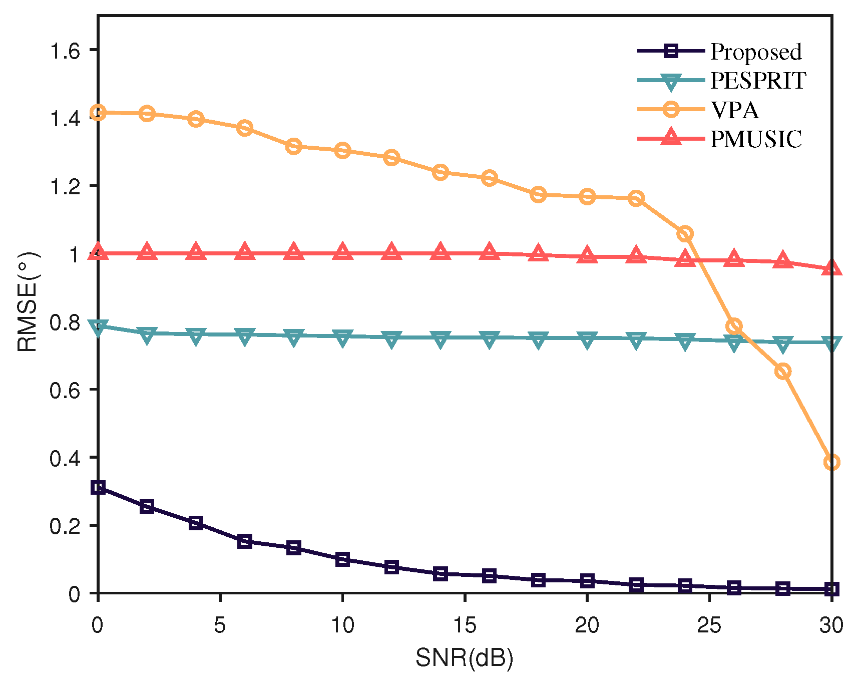
The relevant parameter settings remained consistent with the previous section. We focused on analyzing the following two scenarios: (1) the JSR is fixed at 20 dB, while the SNR varies within [0 dB, 30 dB]; (2) the SNR is fixed at 15 dB, while the JSR varies within [5 dB, 35 dB].
A total of 100 Monte Carlo simulations were conducted, and the results are illustrated in Figure 4 and Figure 5. In the robustness test, the proposed method demonstrates superior stability, followed by PMUSIC and PESPRIT, while VPA exhibits a relatively poorer performance.
The core principle of VPA relies on the polarization-invariant property of the Peak-to-Sidelobe Ratio in pulse compression. It performs parameter estimation using a virtual polarization weighting vector. However, VPA shows sensitivity to both the SNR and JSR. As indicated in Equation (54), VPA achieves optimal estimation performance only when the jamming power significantly exceeds the signal power and the noise power remains sufficiently low.
PCSNR = w P H h T τ T sin c { B ( t τ ) } Peak + u 2 Peak w P H h T τ T sin c { B ( t τ ) } Side + u 2 Side ,
The former constructs a spectral function by exploiting the orthogonality between the jamming polarization vector and the noise subspace to achieve parameter estimation. The latter, however, performs estimation based on the rotational invariance property of polarization vectors. It should be noted that when the jamming power approaches the signal power, the subspace relationship deteriorates, leading to reduced polarization angle resolution. The proposed method in this paper overcomes this challenge through time-domain filtering. As shown in Figure 5, it maintains an estimation accuracy within 0.4° even under a JSR of 5 dB. Consequently, the proposed method exhibits a broader applicable range.
(3) 
Complexity
For a dual-polarized radar receiving system with the number of polarization channels Q = 2 , let N r be the snapshots of the received signal. The proposed jamming polarization estimation method mainly involves two key steps, that is, time-domain filtering and eigenvalue decomposition. Specifically, as shown in Equation (9), the time-domain filtering operation requires Q N r complex multiplications for the complex matrix computation. The construction of the polarization coherence matrix R v in Equation (11) demands Q 2 N r complex multiplications and Q 2 ( N r 1 ) complex additions. The eigenvalue decomposition and eigenvector calculation approximately require Q 3 complex operations. Therefore, the overall computational complexity of the algorithm is 10 O ( N r ) + 4 O ( 1 ) .
In comparison, PESPRIT [11] eliminates the time-domain filtering step but requires an additional matrix eigenvalue decomposition operation. Through complexity analysis, the overall computational complexity of this algorithm is approximately 8 O ( N r ) + 13 O ( 1 ) .
PMUSIC [15] decomposes the echo signal into noise subspace and signal subspace, constructing a spatial spectrum by exploiting their orthogonality characteristics to estimate polarization parameters through spectral peak search. In simulations, given a 1° search step size and a spectral search range of γ J , η J 0 ° , 90 ° , the total number of search iterations is Z = 90 2 . The algorithm’s computational complexity primarily stems from two components: (1) the polarization coherence matrix computation and eigenvalue decomposition, requiring Q 3 + 2 Q 2 N r Q 2 complex-valued operations; and (2) the spatial spectrum construction and peak search, demanding Z 3 Q 2 + Q 1 complex-valued operations. Consequently, the overall computational complexity of the PMUSIC algorithm is approximately 13 O ( Z ) + 8 O ( N r ) + 4 O ( 1 ) .
VPA [19] employs virtual polarization reception technology, with its computational load primarily concentrated on signal pulse compression, PCSNR calculation, and spectral peak search. In simulations, the spectral search range remains consistent with PMUSIC. For each spectral search iteration, signal pulse compression requires approximately 2 N r 2 complex multiplications and 2 ( N r 1 ) 2 complex additions; PCSNR calculation involves identifying the mainlobe peak and maximum sidelobe through traversal, demanding about 2 N r operations. Thus, a single spectral search iteration requires approximately 4 N r 2 + 2 N r operations. With Z total iterations, the final computational complexity of the algorithm is 4 O ( Z N r 2 ) + 2 O ( Z N r ) . The complexity analysis results are summarized in Table 1.
Furthermore, we evaluated the execution time of all four methods on the same platform (MATLAB R2023b, Intel i7-9750H CPU, 16GB RAM). In the experiments, the snapshots were set to N r , with SNR = 10 dB and JSR = 35 dB . For comparative algorithms, the spectral search range was set to γ J , η J 0 ° , 90 ° degrees with a 1° search step size, while other parameters remained consistent with Example 1. Table 1 presents the average time consumption over 100 Monte Carlo simulations.
Comprehensive analysis demonstrates that the proposed algorithm achieves comparable performance to PESPRIT in terms of both computational complexity and efficiency, while PMUSIC exhibits moderately higher complexity and VPA shows the highest computational burden. As evidenced by the experimental results in Example 1, the proposed method significantly improves the estimation accuracy of interference polarization parameters without increasing overall computational complexity, with particularly outstanding performance in scenarios where interference and target powers are comparable.

5.2. Polarization Estimation Analysis of Target

In this case study, we analyzed the composite-feature-projection-based target polarization parameter estimation method proposed in Section 3 from two aspects: robustness and applicability.
(1) 
Robustness
Example 3.
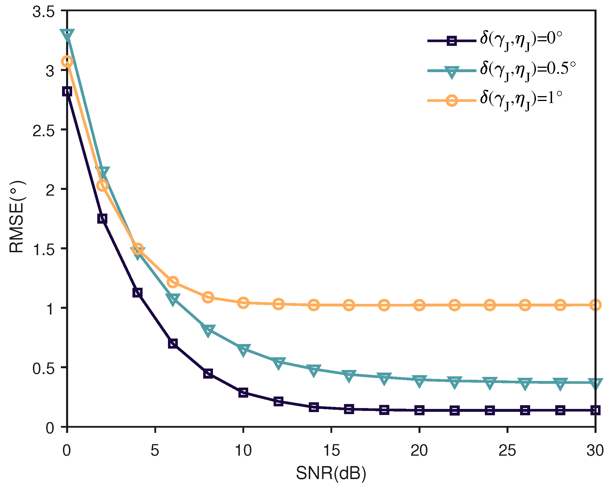
Set the JSR at 30 dB, target radial velocity at 400 m/s, pulse repetition frequency at 8000 Hz, and coherent processing interval at 8 ms. The jamming polarization angle estimation error is set to 0°, 0.5°, 1°, and 1.5°, while the SNR varies within [0 dB, 30 dB]. All other parameters remain consistent with Example 1.
A total of 100 Monte Carlo simulations were conducted, with the results presented in Figure 6, where parameter δ ( γ J , η J ) denotes the polarization angle estimation error.
The results demonstrate that the Doppler velocity estimation performance degrades progressively with increasing polarization angle error. Meanwhile, within the 0–10 dB SNR range, the Doppler estimation accuracy exhibits significant dynamic variations. Cross-referencing with Figure 4 and Figure 5 confirms that the proposed method maintains the polarization angle estimation error within 0.5°, consequently constraining the Doppler estimation error below 1 m/s, which verifies the method’s superior estimation performance.
Example 4.
The pulse repetition frequency (PRF) is set to 8000 Hz with a coherent processing interval of 8 ms. Three experimental scenarios are established: (1) fixed jamming condition, JSR = 30 dB, SNR = 10 dB; (2) variable JSR analysis, the JSR is set to 5 dB, 15 dB, 25 dB, and 35 dB, and SNR varies within [0 dB, 30 dB]; (3) polarization error impact, JSR = 30 dB, jamming polarization angle estimation errors are set to 0°, 0.5°, and 1°, and SNR varies within [0 dB, 30 dB].
The scatter plots comparing target polarization parameter estimation before and after coherent integration are presented in Figure 7. Conventional processing methods directly estimate target polarization parameters via FP, as shown in Equation (24). It fails to achieve effective estimation of target polarization parameters because it cannot eliminate the cross-terms in the covariance matrix. In contrast, the proposed method successfully implements coherent integration through Doppler compensation and range migration correction, effectively suppressing the influence of cross-terms and consequently achieving satisfactory estimation performance.
Figure 8 and Figure 9 demonstrate the target polarization parameter estimation performance under different jamming power levels and polarization angle errors, respectively. Two important observations emerge: first, the method shows significant sensitivity to SNR, exhibiting noticeable performance fluctuations when SNR drops below 10 dB, while maintaining estimation accuracy within 1° when SNR exceeds 10 dB; second, the target polarization estimation performance degrades rapidly when the jamming polarization angle error exceeds 1°. This performance variation stems from two primary factors. One is that the signal’s noise characteristics become altered after pulse compression, phase compensation, and coherent integration processing, causing the eigenvectors to contain both desired signal components and noise contamination in low-SNR environments. The other one is that the estimation errors in jamming polarization angles prevent complete jamming cancellation during orthogonal projection, which not only directly affects Doppler velocity estimation accuracy but also indirectly compromises coherent integration effectiveness, ultimately deteriorating target polarization parameter estimation precision.
(2) 
Applicability
Although the proposed method can achieve polarization parameter estimation of weak target signals under underdetermined conditions, it is limited by the degrees of freedom of the dual-polarization antenna and can only handle mixed signals containing a single target, a single jamming source, and noise.
Moreover, when the jamming polarization vector is close to the target polarization vector, the orthogonal projection may mistakenly filter out the target signal as well, leading to the failure of polarization parameter estimation. It is impossible to distinguish two signals with the same characteristics within the existing dimensions without adding an extra dimension. Therefore, the proposed method requires that the target signal and the jamming signal have distinct polarization characteristics.

5.3. Polarization Suppression of Jamming

Let us analyze the performance of the target polarization projection filter from two aspects: jamming suppression capability and target signal loss.
(1) 
Jamming Suppression Capability
Example 5.
The radar transmits a horizontally polarized signal with a carrier frequency of 1.2 GHz, a pulse width of 25 μ s , a bandwidth of 20 MHz, a pulse repetition frequency of 8000 Hz, a coherent integration interval of 8 ms, and a sampling frequency of 100 MHz. The radial distance between the radar and the target is 90 km, and the target’s polarization scattering matrix S = 1.2 + 1.2 i 0.4 i ; 0.8 i 1.1 . Within one CPI, the radar and the target maintain a radial velocity of 400 m/s. The jammer radiates narrowband spot-frequency jamming, entering through the radar’s main lobe, with the following parameters: f J = 1.22 GHz, τ J = 25 μs, B J = 50 M H z , SNR = 10 dB, and JSR = 30 dB. Three experimental scenarios are established. (1) ( γ J , η J ) = ( 35 ° , 50 ° ) ; (2) the jamming polarization angle estimation error δ ( γ J , η J ) varies within 0 ° , 4 ° ; (3) η J = 45 ° , and γ J varies within 0 ° , 90 ° .
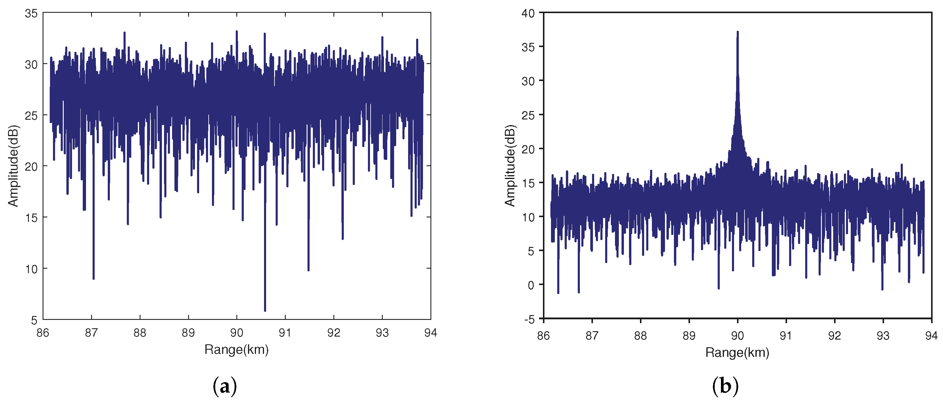
Under parameter configuration (1), Figure 10 presents intuitive filtering results. As clearly observed, the target signal remains undetectable in the unfiltered echo signal even after pulse compression and coherent integration, as shown in Figure 10a. In contrast, after polarization filtering processing (Figure 10b), the jamming is significantly suppressed, making the target echo distinctly visible. Statistical analysis shows an approximately 28.9 dB improvement in SINR. Here, the SINR improvement is defined as
G SINR = 10 log SIN R out SIN R in ,
where SIN R out represents the output SINR after filtering, which can be defined by Equation (49); SIN R in denotes the input SINR before filtering, expressed as SIN R in = σ T 2 / σ J 2 + σ N 2 .
Equation (49) demonstrates that the jamming polarization angle estimation error directly determines jamming suppression performance. Experimental case (2) evaluates how this estimation error affects the output SINR, with simulation results presented in Figure 11. Under perfect jamming polarization angle estimation, the filtering output achieves an SINR of 18.4 dB. However, the filtering performance degrades monotonically as the estimation error increases, confirming the critical importance of accurate polarization parameter estimation for optimal jamming suppression.
Furthermore, Equation (50) reveals that the filter’s capability boundary is primarily determined by two factors: the orthogonality between target and jamming polarization states, and the pre-filtering SNR. In our simulations, the target’s polarization state was set to ( γ T , η T ) = ( 25 . 24 ° , 45 ° ) . When the jamming polarization angle ( γ J , η J ) = ( 115 . 24 ° , 45 ° ) , the filter achieved a peak performance (post-pulse-compression and coherent integration SNR) of approximately 35.05 dB.
As demonstrated in Figure 12, the output SINR asymptotically approaches its theoretical upper bound as parameter γ J approaches the target’s orthogonal polarization direction. Moreover, the filter becomes ineffective when the jamming polarization angle aligns with the target’s γ T 25 ° , as the polarization domain can no longer distinguish between the target and jamming.
(2) 
Target Signal Loss
By setting the weighting coefficient as α 1 = 1 , α 2 = 2 , Equation (51) reduces to
SLR = W TPW H v PA s T PA ( t ) 2 2 W TPW H v PA 2 s T PA ( t ) 2 ,
Example 6.
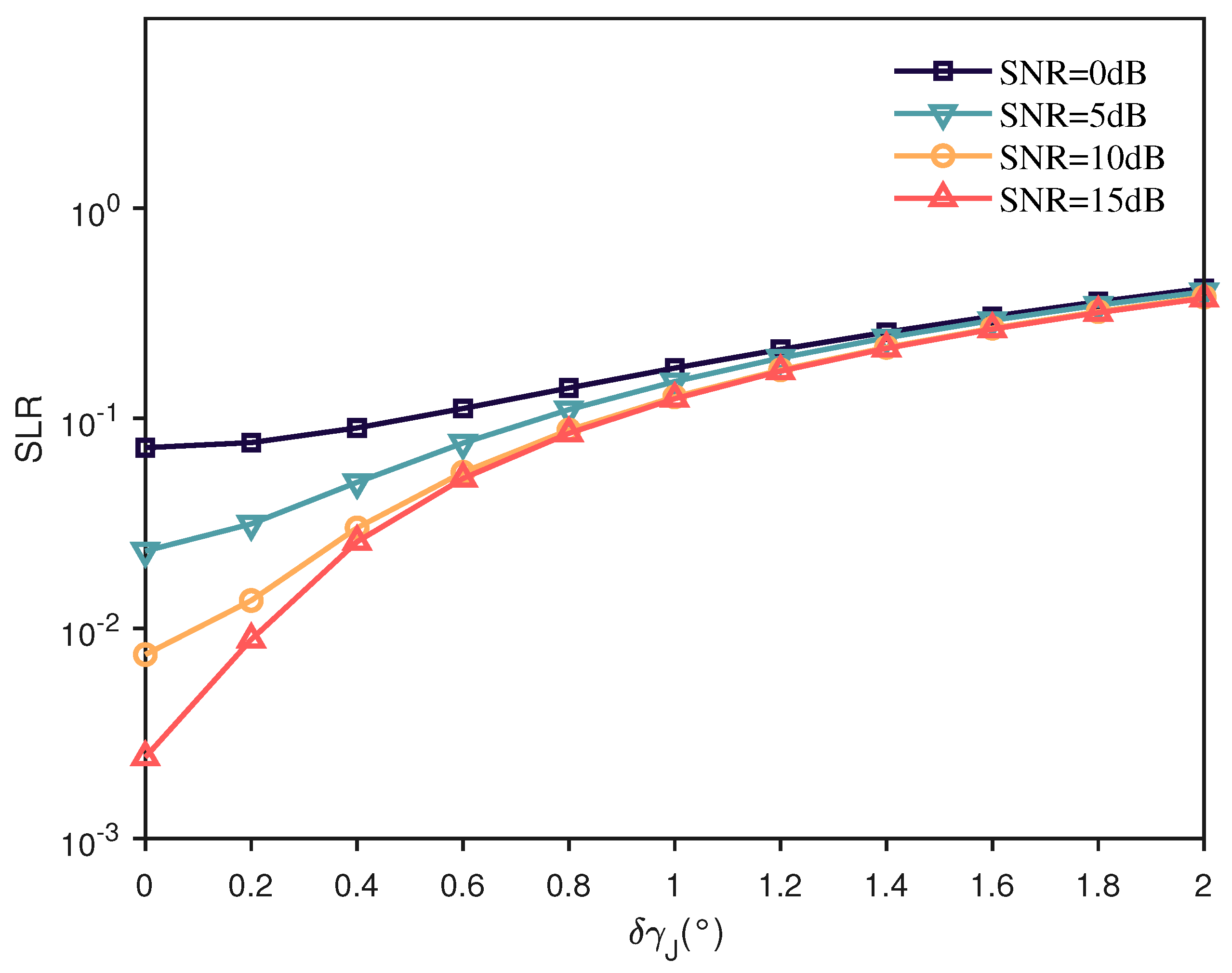
JSR is set to 30 dB, and the jamming polarization state ( γ J , η J ) = ( 35 ° , 50 ° ) . The polarization angle estimation error is 0 ° , 2 ° (with systematic positive bias). SNR is set to 0 dB, 5 dB, 10 dB, and 15 dB. All other parameters remain consistent with the previous example.
As shown in Figure 13, fluctuations in SNR significantly affect target signal loss. This phenomenon stems from two primary factors: first, increased noise power degrades the filter’s inherent performance; second, reduced SNR deteriorates the estimation accuracy of the polarization angle. When the polarization angle deviates from its true value, the signal loss ratio (SLR) exhibits substantial dynamic variations. Therefore, precise parameter estimation serves as a crucial guarantee for superior filtering performance.
Taking SNR = 10 dB as an example, the analysis of Example 3 reveals that with a jamming polarization angle estimation error of δ ( γ J ) 0 . 15 ° , the SLR is approximately 0.02. This demonstrates that the proposed method maintains robust target recovery capability even under such conditions.

6. Conclusions

In this paper, we propose a joint polarization-range-Doppler processing method to address the challenge of co-frequency mainlobe jamming suppression. Based on a dual-polarized antenna structure, we develop a PEES method that achieves precise estimation of the jamming polarization angle with an accuracy within 0.4°, even under low JSR conditions. Through Doppler phase compensation, coherent multi-pulse integration is realized, enabling the proposal of a CFP method that effectively extracts target polarization characteristics from mixed echoes. Building on these developments, we design a target-polarization projection filter using the maximum output SINR criterion and introduce the concept of SLR. The filter’s performance is analyzed and validated in terms of both jamming suppression capability and target loss. Experimental results demonstrate that under conditions of 10 dB SNR and 30 dB JSR, the SINR improvement after filtering reaches 28.9 dB while maintaining the SLR at approximately 0.02.

Author Contributions

Conceptualization, H.H. and L.W.; methodology, Z.L.; writing—review and editing, L.W.; validation, B.X. and T.Z. All authors have read and agreed to the published version of the manuscript.

Funding

This research received no external funding.

Institutional Review Board Statement

Not applicable.

Informed Consent Statement

Not applicable.

Data Availability Statement

Data are contained within the article.

Conflicts of Interest

The authors declare no conflicts of interest.

References

  1. Zhang, M.D.; Lu, J.H.; Xu, J.W.; Li, S.Y. Mainlobe Deceptive Interference Suppression with Planar Frequency Diverse Array MIMO Radar. IEEE Trans. Aerosp. Electron. Syst. 2025; early access. [Google Scholar] [CrossRef]
  2. Zuo, L.; Lan, Z.Y.; Lu, X.F.; Gao, Y.C.; Mao, L.L. Joint Transmit–Receive Filter Design with Lower APSL and ICPL to Suppress Interference. IEEE Trans. Aerosp. Electron. Syst. 2024, 60, 3673–3687. [Google Scholar] [CrossRef]
  3. Shao, S.; Wang, W.Q.; Sun, Y.; Zhang, S.S. Effects of Spatial Position on Mainlobe Interference Suppression Performance of FDA-MIMO Radar. IEEE Trans. Aerosp. Electron. Syst. 2024, 60, 9437–9443. [Google Scholar] [CrossRef]
  4. Zhang, L.; Su, L.H.; Wang, D.; Luo, Y.; Zhang, Q. Mainlobe Interference Suppression for Radar Network via RPCA-Based Covariance Matrix Reconstruction. IEEE Sens. J. 2023, 23, 5094–5108. [Google Scholar] [CrossRef]
  5. Wang, C.J.; Zheng, Z.M.; Zhang, K.X.; Chang, S.Q.; Liu, Q.H. Adaptive Main-Lobe Jamming Suppression Based on Cascaded LMS Filter with Low Cost Distributed Radar. IEEE Sens. J. 2023, 23, 26292–26301. [Google Scholar] [CrossRef]
  6. Wang, Z.; Guo, Z.W.; Shu, G.F.; Li, N. Radar Jamming Recognition: Models, Methods, and Prospects. IEEE J. Sel. Top. Appl. Earth Obs. Remote Sens. 2025, 18, 3315–3343. [Google Scholar] [CrossRef]
  7. Sinclair, G. The transmission and reception of elliptically Polarized Waves. Proc. IRE 1950, 38, 148–151. [Google Scholar] [CrossRef]
  8. Kennaugh, E.M. Polarization Properties of Radar Reflections. Ph.D. Thesis, Ohio State University, Columbus, UK, 1952. [Google Scholar]
  9. Huynen, J.R. Phenomenological Theory of Radar Targets. Ph.D. Thesis, Technical University Delft, Delft, The Netherlands, 1970. [Google Scholar]
  10. Boerner, W.M. Direct and Inverse Methods in Radar Polarimetry; Kluwer Academic Publishers: Alphen aan den Rijn, The Netherlands, 1992. [Google Scholar]
  11. Li, G.; Compton, R.T. Angle and polarization estimation using ESPRIT with a polarization sensitive array. IEEE Trans. Antennas Propag. 1991, 9, 1376–1383. [Google Scholar] [CrossRef]
  12. Li, G. Direction and polarization estimation using arrays with small loops and short dipoles. IEEE Trans. Antennas Propag. 1993, 41, 379–387. [Google Scholar] [CrossRef]
  13. Li, G.; Compton, R.T. Two dimensional angle and polarization estimation using the ESPRIT algorithm. IEEE Trans. Antennas Propag. 1992, 5, 550–555. [Google Scholar] [CrossRef]
  14. Li, G.; Compton, R.T. Angle and polarization estimation in a coherent signal environment. IEEE Trans. Aerosp. Electron. Syst. 1993, 3, 706–716. [Google Scholar] [CrossRef]
  15. Wong, K.T.; Zoltowski, M.D. Self-initiating MUSIC-based direction finding and polarization estimation in spatio-polarizational beamspace. IEEE Trans. Antennas Propag. 2000, 8, 1235–1245. [Google Scholar]
  16. Wong, K.T.; Li, L.S.; Zoltowski, M.D. Root-MUSIC-based direction-finding and polarization estimation using diversely polarized possibly collocated antennas. IEEE Trans. Wirel. Propag. Lett. 2004, 1, 129–132. [Google Scholar] [CrossRef]
  17. Hurtado, M.; Nehorai, A. Polarimetric detection of targets in heavy inhomogeneous clutter. IEEE Trans. Signal Process. 2008, 56, 1349–1361. [Google Scholar] [CrossRef]
  18. Qu, M.C.; Si, W.J.; Liu, R.Z. Oblique Projection DOA Estimation Algorithm Based on Spatial Polarization Characteristics. IEEE Sens. J. 2024, 24, 10809–10823. [Google Scholar] [CrossRef]
  19. He, Y.M.; Yang, J. Polarization Estimation with a Single Vector Sensor for Radar Detection. Remote Sens. 2022, 14, 1137. [Google Scholar] [CrossRef]
  20. Pan, Y.; Gao, X.; Xu, X. Underdetermined estimation of multiple parameters for partially polarized signals with dual-polarized coprime array. IEEE Commun. Lett. 2021, 25, 2923–2927. [Google Scholar] [CrossRef]
  21. Yang, Y.L.; Jiang, G.J. Efficient DOA and Polarization Estimation for Dual-Polarization Synthetic Nested Arrays. IEEE Syst. J. 2022, 16, 6277–6288. [Google Scholar] [CrossRef]
  22. Yang, Y.L.; Shan, M.R.; Jiang, G.J. 2D DOA and Polarization Estimation Using Parallel Synthetic Coprime Array of Non-Collocated EMVSs. Remote Sens. 2024, 16, 3004. [Google Scholar] [CrossRef]
  23. Yang, Y.L.; Shan, M.R.; Jiang, G.J. 2D DOA and polarization estimation via synthetic nested dual-polarized array with scalable aperture in the presence of unknown nonuniform noise. Digit. Signal Process. 2025, 158, 104932. [Google Scholar]
  24. Nathanson, F.E. Adaptive circular polarization. In Proceedings of the IEEE International Radar Conference, Arlington, VA, USA, 21–23 April 1975; pp. 221–225. [Google Scholar]
  25. Mao, X.P.; Liu, Y.T. Null phase-shift polarization filtering for high-frequency radar. IEEE Trans. Aerosp. Electron. Syst. 2007, 43, 1397–1408. [Google Scholar] [CrossRef]
  26. Mao, X.P.; Liu, A.J.; Hou, H.J. Oblique projection polarization filtering for interference suppression in high-frequency surface wave radar. IET Radar Sonar Navig. 2012, 6, 71–80. [Google Scholar] [CrossRef]
  27. Liu, A.J.; Mao, X.P.; Deng, W.B. Oblique projection polarization filtering and its performance in high frequency surface wave radar. In Proceedings of the 2010 International Conference on Microwave and Millimeter Wave Technology, Chengdu, China, 8–11 May 2010; pp. 1618–1621. [Google Scholar]
  28. Zhang, X.; Cao, D.; Xu, L. Joint polarization and frequency diversity for deceptive jamming suppression in MIMO radar. IET Radar Sonar Navig. 2012, 13, 263–271. [Google Scholar] [CrossRef]
  29. Ma, J.Z.; Shi, L.F.; Xiao, S.P.; Wang, X.S. Mitigation of cross-eye jamming using a dual-polarization array. J. Syst. Eng. Electron. 2018, 29, 491–498. [Google Scholar]
  30. Dai, H.Y.; Wang, X.S.; Li, Y.Z.; Liu, Y.; Xiao, S.P. Main-Lobe Jamming Suppression Method of using Spatial Polarization Characteristics of Antennas. IEEE Trans. Aerosp. Electron. Syst. 2012, 48, 2167–2179. [Google Scholar] [CrossRef]
  31. He, Y.M.; Zhang, T.; He, H.F.; Zhang, P.R.; Yang, J. Polarization Anti-Jamming Interference Analysis with Pulse Accumulation. IEEE Trans. Signal Process. 2022, 70, 4772–4787. [Google Scholar] [CrossRef]
  32. Poelman, A.J.; Guy, J.R.F. Multinotch logic product polarization suppression filters: A typical design example and its performance in a rain clutter environment. IEE Proc. F Commun. Radar Signal Process. 1984, 131, 383–396. [Google Scholar] [CrossRef]
  33. Wang, M.; Luo, X.X.; Dong, J. Anti-Jamming Algorithm of Polarization-Sensitive Array Based on Improved Constraint Matrix and Orthogonal Subspace Projection. IEEE Sens. J. 2023, 23, 30835–30846. [Google Scholar] [CrossRef]
  34. Wang, X.S.; Xiao, S.P.; Tao, H.M.; Zhuang, Z.W. Nonlinear optimization method of radar target polarization enhancement. Prog. Nat. Sci. 2000, 10, 136–140. [Google Scholar]
  35. Hou, H.J.; Mao, X.P.; Li, S.B. A generalized oblique projection operator for interference suppression under colored noise. In Proceedings of the 2012 IEEE Radar Conference, Atlanta, GA, USA, 7–11 May 2012. [Google Scholar]
  36. Veen, B.V.; Buckley, K.M. Beamforming: A versatile approach to spatial filtering. IEEE Acoust. Speech Signal Process. Mag. 2002, 5, 4–24. [Google Scholar] [CrossRef]
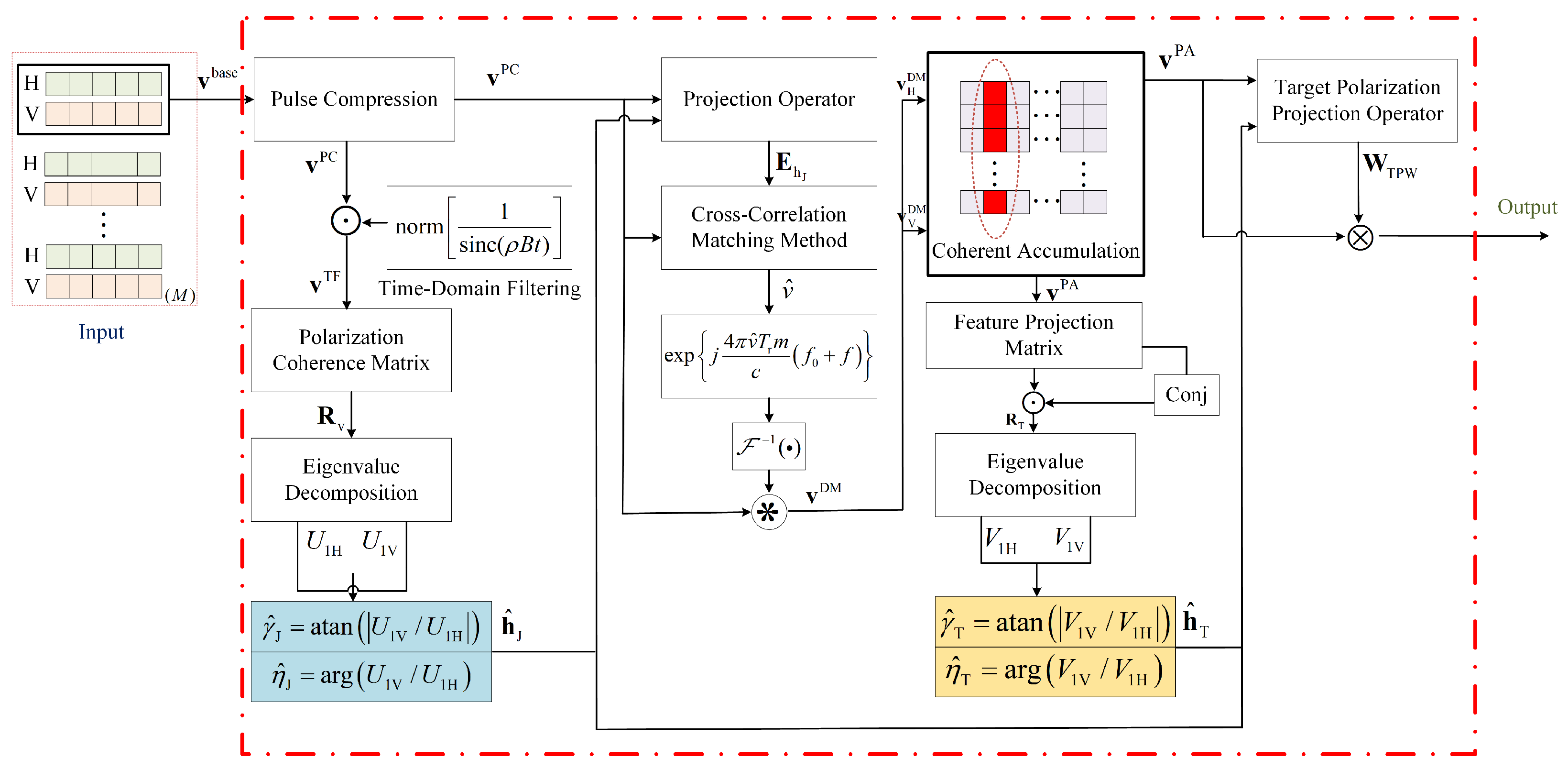
Figure 1. Flow diagram of anti-mainlobe jamming via polarization-range-Doppler processing.
Remotesensing 17 01995 g001
Figure 2. Estimation error for jamming polarization estimation (a) The proposed method and (b) PESPRIT method.
Remotesensing 17 01995 g002
Figure 3. Comparison of scatter plots for jamming polarization estimation under (a) JSR = 5 dB, (b) JSR = 20 dB, and (c) JSR = 35 dB.
Remotesensing 17 01995 g003
Figure 4. Jamming polarization estimation accuracy under varying SNR conditions at JSR = 20 dB.
Remotesensing 17 01995 g004
Figure 5. Jamming polarization estimation accuracy under varying JSR conditions at SNR = 15 dB.
Remotesensing 17 01995 g005
Figure 6. Estimation accuracy of target radial velocity under different SNR levels and jamming polarization angle errors.
Remotesensing 17 01995 g006
Figure 7. Scatter plot of target polarization parameter estimation before and after coherent integration under conditions of JSR = 30 dB and SNR = 10 dB.
Remotesensing 17 01995 g007
Figure 8. The impact of SNR and JSR on the accuracy of target polarization parameter estimation.
Remotesensing 17 01995 g008
Figure 9. The impact of SNR and jamming polarization angle error on the accuracy of target polarization parameter estimation.
Remotesensing 17 01995 g009
Figure 10. One-dimensional range profiles before and after filtering. (a) Signal in horizontal polarization channel after pulse compression and coherent integration; (b) processed signal following TPPF.
Remotesensing 17 01995 g010
Figure 11. Relationship between output SINR and jamming polarization angle error.
Remotesensing 17 01995 g011
Figure 12. Relationship between jamming polarization angle and filter performance.
Remotesensing 17 01995 g012
Figure 13. Impact of SNR and jamming polarization angle error on target signal loss ratio.
Remotesensing 17 01995 g013
Table 1. Computational complexity and computation time comparison.
MethodComputational ComplexityAverage Time (ms)
Proposed 10 O ( N r ) + 4 O ( 1 ) O ( N r ) 3.8
PESPRIT 8 O ( N r ) + 13 O ( 1 ) O ( N r ) 4.2
PMUSIC 13 O ( Z ) + 8 O ( N r ) + 4 O ( 1 ) O ( Z ) + O ( N r ) 41.1
VPA 4 O ( Z N r 2 ) + 2 O ( Z N r ) O ( Z N r 2 ) 665.7
Disclaimer/Publisher’s Note: The statements, opinions and data contained in all publications are solely those of the individual author(s) and contributor(s) and not of MDPI and/or the editor(s). MDPI and/or the editor(s) disclaim responsibility for any injury to people or property resulting from any ideas, methods, instructions or products referred to in the content.