1. Introduction
Drones have emerged as a promising platform with applications in multiple fields, and demonstrate superior military utility [
1,
2,
3]. The most essential telemetry information for drone pilots is the altitude from the Earth’s surface, which is required to enable both collision avoidance and navigation. High-altitude accuracy levels are very important, not only for flight safety but also for remote sensing applications such as aerial mapping or precision-agriculture techniques. Conventional methods used to obtain the altitude for drones include inertial measurement units (IMUs), global navigation satellite systems (GNSSs), barometers, camera images, radar systems, and acoustic sensors; all operate using a variety of mechanisms and all have their own drawbacks [
4,
5,
6,
7,
8,
9]. The errors in IMUs can rapidly diverge, which leads to the altitude becoming unavailable. A GNSS can only provide the height relative to the Earth’s ellipsoid surface, while a barometer can only give the height relative to sea level [
10]. Kinematic GNSS RTK methodology can give results with decimeter-level accuracy when applying ellipsoidal heights, quasigeoid models, and digital terrain models [
11,
12,
13]. However, as the models are not dynamic enough, it is difficult to reflect the real situation. Camera images require auxiliary spatial information, while the concealment capability when using acoustic sensors is very poor [
8,
14]. Among the conventional techniques mentioned above, GNSSs and barometers cannot directly provide drone heights from the ground. The measurement accuracy of low-cost IMUs is very poor and rapidly deteriorates. Radar and acoustic systems can provide drone heights directly from the ground with high accuracy but they have poor concealment properties and are not suitable for military applications. The accuracy of the solutions from camera images varies in different environments and heavily relies on auxiliary spatial information. GNSS reflectometry (GNSS-R)-based altimetry has been proposed to measure sea surface heights for over 30 years, and offers advantages that include good concealment, a low cost, the ability to directly measure the height above the Earth’s surface, and no range limitations [
15].
Table 1 lists the characteristics of different techniques for drone height determination from the ground. Here, the criteria for judging the stealthiness mainly derived from whether the sensor would actively emit signals. In this article, for those sensors that could actively emit signals, we considered their stealthiness performance to be good. Conversely, those that could not were considered to have poor stealthiness performance. We propose—for the first time—the use of this technique to measure drone heights to overcome the current technical bottlenecks faced when using conventional methods.
The method of determining drone heights from the ground using GNSS-R is proposed in this paper for the first time (to the best of our knowledge); the only relevant or related studies in the literature consider aspects such as drone altitude estimation, GNSS-R reflector height estimation, and GNSS-R vegetation canopy height retrieval [
16,
17,
18].
In drone navigation algorithms, researchers have identified multi-source data fusion as an important method to obtain highly accurate unmanned aerial vehicle (UAV) altitude information, and several types of algorithms have been proposed [
6]. LiDAR and radar sensors can measure the above ground level (AGL) parameter but they have relatively poor concealment properties [
18,
19]. Currently, there is no sensor that can covertly and directly measure the height of a drone above the ground in all weathers without a requirement for auxiliary information.
In addition, there are some related research approaches, such as vision-based landing for UAVs and UAV and unmanned ground vehicle (UGV) cooperative systems, which can also provide the AGL [
20,
21,
22]. Vision navigation has higher guidance and positioning accuracy when combined with other navigation methods. These systems offer enhanced situational awareness and operational efficiency, enabling complex tasks that are beyond the capabilities of individual systems by leveraging the complementary strengths of UAVs and UGVs.
The GNSS-R technique was proposed in 1993 to determine sea surface heights from measurements of the path delay between the direct and reflected signals; the reflector height should be calculated first in this approach [
15]. Recently, many experiments have been performed using different platforms, showing promising results in the fields of sea surface altimetry and vegetation canopy height retrieval based on these path delay measurements [
23,
24,
25]. In ground-based platforms, sea surface heights have been determined with centimeter-level accuracy, while the accuracy of reflector heights obtained using shipborne platforms has been at the decimeter level [
17,
26]. As airborne GNSS-R can provide better observations with improved spatial resolution compared with spaceborne examples and offer wider observation ranges than ground-based scenarios, several experiments have been conducted to test the performance of these airborne systems. An airborne GNSS-R experiment for vegetation canopy height retrieval was performed using dual-frequency Global Positioning System (GPS) signals, and solutions with a root mean square (RMS) error of approximately 4.0 m were derived [
16]. Water surface heights were also derived, with accuracy on the decimeter to meter scale, from airborne GNSS-R measurements [
27,
28]. For spaceborne GNSS-R examples, retrievals of tree heights and sea surface heights have been studied, with promising results being shown in the cases of water-level and land topography measurements [
29,
30,
31,
32].
The signals are transmitted from more than 100 GNSS satellites rather than from the sensors on the drones, and these signals can be reflected by both water and land surfaces. Multiple reflector heights can, therefore, be retrieved using the signals transmitted from the satellites in different directions. Consequently, when compared with conventional techniques to measure the altitudes of drones, the GNSS-R technique is highly covert, consumes little power, has no maximum range limitation, and is applicable in a variety of scenarios [
33,
34]. Therefore, this paper introduces this technique for use in drone height retrieval. It can also provide additional observations for use in multi-source fusion navigation.
As drone height determination using this approach has not been previously studied, we performed GNSS-R experiments using a drone carrying a GNSS-R setup that was used to study a baseband signal processing algorithm for the first time. The raw intermediate frequency (IF) data at 62 MHz for two frequencies were collected and postprocessed using a software-defined receiver (SDR) to resolve the path delay measurements using GPS/BDS signals. Then, in combination with the GNSS-R geometric relations, the reflector heights were resolved and evaluated via GNSS real-time kinematic (RTK) measurements.
The rest of this paper is organized as follows. The algorithm for our proposed method of height retrieval and baseband signal processing is described in detail in
Section 2.
Section 3 introduces the experimental setups and describes the processes.
Section 4 shows the results obtained and presents their analysis.
Section 5 summarizes the work in this paper and discusses the limitations of the research.
2. Materials and Methods
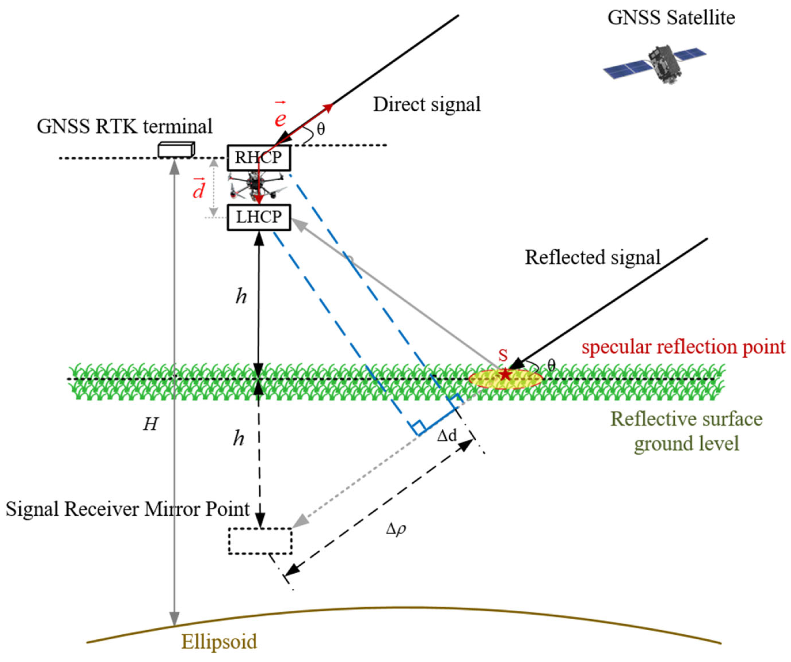
This paper proposes a method to determine the height of a drone above the ground using GNSS-R. The method involves equipping the drone such that it carries an IF data collector connected to an upward-facing right-hand circularly polarized (RHCP) antenna and a downward-facing left-hand circularly polarized (LHCP) antenna to receive the direct GNSS signal and the signal reflected from the ground, respectively. The raw IF data are then processed using a self-developed GNSS-R software-defined receiver to resolve the path delay measurements, and the reflector heights are then calculated. The SDR was developed by ourselves based on an open source code using MATLAB [
35] that was introduced in detail in our previous work [
17,
26]. A schematic diagram of the GNSS-R drone-based altitude retrieval procedure conducted in this study is shown in
Figure 1.
In this study, specular reflection signals were mainly used, and the direct and reflected signals could be regarded as being in parallel. Here, the geometric configuration for classical GNSS-R altimetry was used. In
Figure 1,
represents the vertical distance from the phase center of the reflected antenna to the ground.
represents the geodetic height of the RHCP antenna.
represents the Fresnel reflection zone of the specular reflection point.
denotes the elevation angle of the GNSS satellite.
represents the unit vector between the satellite and the phase center of the upward-looking antenna.
represents the vector between the phase centers of the upward-looking and downward-looking antennas.
represents the path delay between the direct and reflected signals, where
. Based on the geometric relationships shown in
Figure 1, the following equations could be derived:
Multiple error factors are associated with the actual code chip path delay, including hardware biases, reflector surface deviations, measurement errors, and other unmodeled errors. Therefore, the path delay can be expressed more comprehensively as follows:
where
represents the total path delay difference between the direct signal and the reflected signal from the satellite to the receiver.
represents the bias between the direct and reflected channels caused by hardware errors.
denotes the reflector surface deviation caused by the terrain reflection characteristics and the vegetation coverage.
denotes the measurement error.
represents the unmodeled errors. Finally, the vertical height above the reflecting surface of the UAV could be determined using Equations (1) and (2) as follows:
As the signals reflected from land are much weaker than those reflected from a water surface, longer incoherent integration times should be selected for the acquisition of effective signals. In this study, an SDR was used to process the raw IF data, reducing the number of noncoherent accumulations appropriately, which improved efficiency. The baseband signal processing method was as follows. (1) The direct and reflected signals were processed using the same locally generated code sequence to perform the correlation. (2) The synchronized digital signals of the direct and reflected GNSS signals were initially subjected to 10 ms coherent integration with the local BDS B1C code onboard. For the BDS and B2a, GPS L1C/A, and L5 codes, a 1 ms coherent integration was performed, followed by multiple rounds of noncoherent integration. (3) The direct and reflected GNSS signal waveforms were obtained, and the peak positions of these waveforms were then identified.
The cross-correlation waveforms for the BDS B1C and B2a codes as well as those for GPS C/A and L5 for the direct and reflected signals obtained in the drone-mounted experiments are shown in
Figure 2.
Figure 2a–d present the waveforms of the BDS C39, B1C, B2a, GPS G26 C/A, and L5 signals, respectively. The horizontal coordinates represent the sequence of the sampling points, while the vertical coordinates represent the integral values. The blue color indicates the direct signals and the red color indicates the reflected signals. The reflected signals were weaker than the direct signals in all cases, and the GPS C/A reflected signal was relatively weaker than the other reflected signals. Although BDS B1C and GPS C/A have the same code rate, BDS B1C signals have advanced BOC modulation, which results in a sharper waveform [
36]. Thus, the waveform of BDS B2a was similar to that of GPS L5 because they had the same code rate and modulation. The path delay difference between the direct and reflected GNSS signals was determined based on the differences between their waveform peak positions. The height of the aircraft above the ground was then retrieved using a signal reflection model in combination with the terrain reflection characteristics and the vegetation coverage.
Noise, bias, and multipath effects inevitably exist in raw GNSS signals. The noise and bias of this raw IF data recorder was reported in our previous work. The noise level of different-ranging code measurements was within 0.2 m in most cases, while the bias was at the centimeter level [
37]. As the accuracy of our solutions was at the meter level, the noise and bias of the raw IF data could be ignored. To suppress the multipath effect, the base of the antenna used in this experiment comprised a metal plate with a thickness of 3.5 mm. A choke ring layer was added to the side, encircling the antenna. This could effectively suppress signals entering from the back and side of the antennas and reduce the cross-talk effect [
38].
3. Experiment and Setups
3.1. Experimental Site and Environment
On 29 October 2024, GNSS-R drone experiments for height retrieval were performed over two land types, comprising bare soil and apple orchards. The study area was located within an experimental farm field of the Weihai Academy of Agricultural Sciences in Wangtuan Town, Huancui District, Weihai City, Shandong Province, China, at geodetic latitude/longitude coordinates of 37°20′N/122°00′E and an elevation of approximately 50 m.
Figure 3 shows photographs of the experimental sites. The bare soil plot was both flat and open, whereas in the apple orchards, the trees were planted in rows that were spaced approximately 3–4 m apart and they had bright green foliage. The two experimental flights took place in very light wind conditions, so the drone’s attitude was stable in both cases. Because of the limited battery life of the drone, approximately 10 min of IF data were collected over the bare soil and approximately 10 min of IF data were collected over the apple orchard. The soil moisture values of the two plots were measured using a time-domain reflectometer (TDR), which gave values of 0.32 in the apple orchard and 0.27 in the bare soil. The weather conditions were favorable, with no wind at the time the experiment was carried out.
Another experiment was conducted on 12 March 2025 to test the performance of the techniques over an urban road, which was located on the campus of Shandong University, Weihai. About 10 min of raw IF data were collected and processed using the above method.
Figure 4 shows the sky plots for the BDS-3 and GPS satellites for periods of about 0.5 h before and after the experiments over farmland. We can see from these plots that the number of visible satellites for both systems was around a dozen. As signals from higher elevations can provide better results, we initially focused our study on the BDS C39 and GPS G26 satellites, which transmit dual-frequency signals on B1C/B2a, GPS C/A, and L5. Both GPS G16 and G31 do not transmit L5 signals. The baseband signal processing algorithms were tested using the signals from the BDS C39 and GPS G26 satellites. Then, as the limitation of antenna beam angle and locations of the specular points were ascertained, the signals from the satellites with elevations above 30° were processed.
3.2. Experimental Setups
The drone used in this study was a DJI Matrice 600 Pro (Shenzhen, China), which has a maximum payload weight of 5 kg. The RHCP antenna and the LHCP antenna had the same parameters, apart from their different polarizations, and they could receive signals from all GNSS frequency points with a gain of 5.5 dBi and a beam angle of approximately 80°.
The IF data recorder had four radio frequency (RF) channels with a common clock, with one channel connecting to the B1/L1 direct signal, one channel connecting to the B1/L1 reflected signal, one channel connecting to the B2/L5 direct signal, and one channel connecting to the B2/L5 reflected signal. The sampling rate for the IF data was 62 MHz with 2-bit quantization, and the data were stored in real time on a solid-state drive (SSD) integrated into the IF signal collector. The data were postprocessed using an SDR to calculate the path delays between the direct and reflected signals. Then, the reflector heights were retrieved.
Figure 5 shows a photograph of the drone carrying the GNSS-R setups used in the experiments. This was a six-rotor drone with an RHCP antenna located at the top, a miniaturized IF signal collector in the middle, and an LHCP antenna hanging below the drone body but above the ground. The dimensions of the antenna were 13 × 13 × 3.5 cm
3, while those of the collector were 21 × 14 × 3 cm
3. The overall dimensions of the drone were 166.8 × 151.8 × 72.7 cm
3. The drone and the antennas were powered using lithium batteries. The RHCP antenna and the LHCP antenna were located on the same vertical line. As there was no wind during our experiment, the phase centers of the two antennas could be kept on the same plumbline at all times, even when the drone was in the air.
3.3. In Situ Measurements
The in situ measurements were obtained using GNSS RTK observations and the drone heights from the ground were the GNSS geodetic heights of the drone subtracted from the ground’s GNSS geodetic height. The Septentrio PolaRx5 is a versatile and robust full-system, full-frequency GNSS reference station receiver with unique interference monitoring and suppression capabilities. The PolaRx5 was installed as a positioning base station for use in the GNSS-R drone altimetry experiment on the roof of a building, which was located approximately 20 km away from the experimental site. The GNSS RTK positioning terminal was mounted on and fixed to the drone with an attached RHCP antenna and was powered using a 12 V battery. The output file format of the device was National Marine Electronics Association (NMEA) 0183, and it could provide centimeter-level positioning information in real time.
4. Results
As multiple pairs of direct and reflected GNSS signals with two frequencies from different directions could be simultaneously received, multiple drone heights were derived. The drone heights from the ground obtained using GNSS-R were derived from path delay measurements that were separately resolved from the GPS L1 C/A and L5 signals and the BDS B1C and B2a signals. There are multiple factors that can affect the accuracy of solutions, mainly involving the algorithm used and the characteristics of the observations. Satellite signals with higher elevations have better signal quality, according to previous studies, so we used the signals from BDS C39 and GPS C26 to test the baseband signal processing algorithms and assess the effects of different numbers of incoherent accumulations on the retrieval accuracy [
17]. Most SDRs run very slowly when they process IF data with a high sampling rate. As an SDR was used in this study, we intended to find a trade-off between inversion accuracy and processing efficiency.
Figure 6,
Figure 7,
Figure 8 and
Figure 9 illustrate the drone height differences between the GNSS RTK observations and the GNSS-R retrievals, which were derived from BDS C39 and GPS G26, with different numbers of incoherent accumulations over both the bare soil and the apple orchard. In these figures, the squares, circles, triangles, diamonds, and stars represent the height differences when calculated from 2, 10, 25, 50, and 100 incoherent integrals, respectively.
Figure 10 shows the RMS errors in the drone height differences between the GNSS-R retrievals and the GNSS RTK observations for the different numbers of incoherent accumulations.
Figure 6 and
Figure 7 show the results recorded over the bare soil. The overall accuracies ranged from 1 to 3 m. With the exception of BDS C39 and B1C, all signals were continuous. It should be noted here that the elevation angle range of the BDS C39 satellite was from 79° to 80° and that of the GPS G26 satellite was from 58° to 54°. The accuracy of the solutions resolved from the GPS C/A signal was the worst, followed by those derived from BDS B1C. BDS B2a and GPS L5 demonstrated the best performances and had comparable accuracies. As the code rates of BDS B2a and GPS L5 were ten times those of BDS B1C and GPS C/A, these results indicated that solutions with higher accuracy could be achieved by using signals with higher code rates. As B1C signals are modulated using more advanced modulation methods, their inversion accuracies were also higher than those of the C/A codes. BDS B2a and GPS L5 use similar modulation methods and the same code rate; thus, their retrieval results had similar accuracies. However, the overall accuracies of the solutions obtained were higher for incoherent cumulative count values of 10 and 25 in most cases, whereas the accuracies tended to deteriorate for incoherent cumulative counts of 2 and 100. As the reflected signals from land are much weaker than those reflected from a water surface, multiple incoherent accumulations are necessary and can enhance the signal-to-noise ratio to allow effective waveforms to be obtained. However, longer incoherent integration times contain more clutter, which affects the ranging accuracy. Shorter incoherent integration times affected the reliability of the observations. In addition, for the case where there were only two incoherent integrals, the numbers of effective observations were significantly reduced.
Figure 8 and
Figure 9 show the corresponding results from experiments over the apple orchard. Here, the elevation angle range of the BDS C39 satellite was approximately 80° and that of the GPS G26 satellite was from 52° to 49°. In contrast to the bare soil situation, the land surface became rougher because of the presence of the apple trees. The BDS C39 satellite provided a similar performance over the apple orchards to that obtained over bare soil for both the B1C and B2a signals. However, when compared with the bare soil case, the accuracy of the GPS G26 retrievals over the apple orchard showed significant degradation. We can see from
Figure 10 that the SNR values of both the L1 C/A and L5 signals from G26 over bare soil were higher than those over the apple orchard. This indicated that the land surface roughness had a major impact on the accuracy of solutions derived from signals at lower elevations, and the power of the reflected signals also significantly decreased.
Figure 11 and
Figure 12 show the corresponding results from experiments over an urban road. The elevation angle range of the BDS C40 satellite during this experiment was approximately 72°, and that of GPS G06 was about 40°. The accuracy of solutions retrieved from BDS C40 was very high, while that of GPS G06 was relatively low, similar to the bare soil situation. The specular points of the reflected signals from BDS 40 were on the road, which was very flat and paved with asphalt. This indicated that the GNSS signal reflected by the asphalt road contained a relatively large number of coherent components, which enabled us to achieve higher precision. However, those from GPS G06 were located on the green belt, with trees, grass, and landscape stones. As the landscape of the urban green belt was similar to the farmland, the accuracies of retrievals lay between those of bare soil and the apple orchard. In addition, we observed that the signals of GPS G06 L5 were severely interrupted and, during the interruption, the effective observations of the C/A code signal also decreased. The code chip length of L5 was only one-tenth of that of the C/A code, which was more susceptible to the influence of surface roughness. Here, we posited that there was a big tree and landscape stones near the specular point.
Figure 13 shows that the retrievals based on 10, 25, and 50 incoherent accumulations had similar performances. As fewer incoherent accumulations can improve computational efficiency, 10 incoherent accumulations were selected for use in the baseband signal processing to process the other signals at lower elevations.
Figure 14 and
Figure 15 show the drone height differences between the GNSS-R retrievals that were derived from other available BDS-3 and GPS satellites with 10 incoherent accumulations and the GNSS RTK observations. The figures show that the retrieval accuracies were better than 10 m in most cases. The retrievals from BDS B2a and GPS L5 both had higher accuracies than those obtained from BDS B1C and GPS C/A. This demonstrated that signals with a higher code rate had better performance when the elevations were relatively low. In addition, the overall accuracies of these solutions were worse than those from BDS C39 and GPS G26 because of their lower elevations.
Figure 16 shows the residuals for the road scenario, and all the results are given in the same figure due to few available signals. GPS G17 and G19 did not transmit L5 signals, while the other available BDS satellite was C38 (in addition to C40). BDS B2a had the best performance.
Figure 17 shows the cumulative probability density of drone height differences between the GNSS-R retrievals and the corresponding GNSS RTK observations for different terrains and GNSS signals. Overall, the accuracy of the solutions for bare soil was slightly better than that for the apple orchard, and the observations with high elevations had better performance.
In order to improve the accuracy of the GNSS-R retrievals, a 30 s moving average was applied for the solutions with 10 incoherent accumulations. The results for different cases are shown in
Figure 18. Compared with the original results, the accuracies improved and the most accurate results reached 0.5–1 m.
Figure 19 shows the relationship elevations and RMSEs of the solutions. The overall accuracy improved with an increase in the elevation angle. As the beam angle of the antennas was approximately 90 degrees, it was insensitive to signals at low elevation angles. In order to improve the performance of solutions derived from the signals with low elevations, the antenna needed to be installed facing the side of the drone.
The accuracy of solutions with high elevations was relatively high compared with that of low elevations. It was necessary to fuse the solutions derived from multiple signals. In order to improve the performance, we fused the observations of the B2a and L5 signals with high elevations. However, we observed that the integration of multiple observations did not yield a comprehensive improvement in retrieval accuracy, with performance even lagging behind the optimal single-source approach. Therefore, the optimization strategy we proposed was for a flat surface when there were observations with a higher elevation angle, directly taking the solutions derived from the signal with the higher elevation angle.
As mentioned in the Introduction, the superiorities of GNSS-R over other conventional techniques include availability, continuity, consistency of accuracy, and concealment. GNSS satellites continuously transmit signals around the clock and in all weather conditions, and concealment can be ensured owing to the passive remote sensing of GNSS-R. The results showed that the solutions were continuous and the accuracy was meter-level.
5. Discussion
A drone’s height from the ground is an important parameter to ensure that the drone has a safe flight and fulfills its established tasks. This paper proposes GNSS-R as a new and effective method to measure the height of a drone from the ground. This method has no measurement range limitations and can directly obtain the height from the ground with good concealment. BeiDou Satellite Navigation System (BDS) and Global Positioning System (GPS) satellites were used as signal sources for the experiments. The initial results showed that the precision of the original solutions obtained could reach approximately 2 m compared with the GNSS RTK results. It was found that the accuracy of the airborne GNSS-R altimetry experiments was affected by the satellite elevation angle, the signal frequency band, the number of incoherent accumulations, and the roughness of the land surface.
This paper determined the heights of drones over the Earth’s surface using GNSS-R. This is important for flying safety in geodetic and cartographic works, etc. We carried out a few practical experiments, and our results showed that the drone height retrieval accuracy could meet the requirements of preliminary applications. This confirmed the feasibility of using GNSS-R to detect drone heights based on dual-frequency GPS/BDS signals.
Higher accuracies of the solutions derived from the signals modulated using more advanced modulation methods could be achieved. In different cases, multiple results showed that the accuracy of the solutions resolved from the GPS C/A signal was the worst. In future research, priority should be given to the new generation of GNSS signals.
In baseband signal processing, a noncoherent integration duration needs to be reasonably determined. In this study, the results demonstrated that better results with relatively little computational consumption could be achieved when 10 and 25 incoherent accumulations were used. Too long or too short a noncoherent integration time could cause a reduction in the accuracy of altimetry retrievals.
The accuracies of the solutions derived from the signals transmitted from the GNSS satellites with high elevations were higher, especially for the reflecting surface with greater roughness. In our studies, the accuracies of the solutions derived from BDS C39 over bare soil land and an apple orchard were similar, while the accuracies of the solutions derived from GPS G26 over bare soil land and an apple orchard were quite different.
In our study, only the signals from a high elevation were used to find a compromise between inversion accuracy and processing efficiency. It is noteworthy that the optimized number of incoherent integrals was related to different intensities of signals as well as the number and type of visible satellites. This is a complex issue, which requires a large number of measurements. As the endurance of drones is limited, we did not have enough data to support this research at this time. Thus, an algorithm to find the optimal solution should be further studied based on more effective data.
The accuracies of GNSS-R measurements vary with complex terrains and different meteorological conditions. Our preliminary experiments were only carried out over flat bare soil land and an apple orchard when the weather was sunny and windless. The performance of GNSS-R for drone height determination needs to be validated using more complex terrains and higher flight heights from the ground. For example, there are many buildings that can affect the measurement accuracy in an urban environment. It is worth noting that if drones fly over dense forests, the solutions are highly likely to be the height from the vegetation canopy and not the ground. In this case, the reflected GNSS signal may indirectly originate from the ground surface and could be received to be used for height retrievals, which would lead to a sharp decrease in inversion accuracy. In future work, the equipment should be upgraded so that experiments can be carried out using more complex scenarios. By utilizing these data, we can conduct more in-depth and detailed analyses.
In this work, an SDR with MATLAB was used to process the raw IF data, which ran very slowly but could be used to test the algorithm for baseband signal processing. We merely validated the fundamental principles and feasibility of the technology, and it could not meet the real-time application requirements. GNSS signals reflected from different Earth surfaces vary in strength and multipath effects, necessitating distinct baseband signal processing algorithms. This paper reports the results of different baseband signal processing algorithms using an SDR. In the next step, the method could be transformed into a real-time processing algorithm using the FPGA + DSP mode. We will upgrade the setups based on the FPGA + DSP mode, which can run in real time and meet the requirements of real-time navigation and obstacle avoidance for drones.
In order to further analyze the performance of the technique for drone height above ground determination, the drone should fly higher and a comparison with other systems should be provided. Unfortunately, there are drone flight height restrictions in the experimental area and we had no other techniques to determine the flight height except GNSS RTK. In the next step of our work, we will use larger aircraft that can fly higher to carry out experiments with a view to further verifying the effectiveness of the technology, and the impact of attitude and flight height on GNSS-R altimetry will be taken into consideration [
39].
Author Contributions
Conceptualization, W.Q.; methodology, L.Z. and F.G.; software, L.Z. and F.G.; validation, L.Z., W.K., and Y.Z.; formal analysis, L.Z. and W.K.; investigation, L.Z.; resources, L.Z.; data curation, L.Z.; writing—original draft preparation, L.Z.; writing—review and editing, F.G. and W.K.; visualization, Y.Z.; supervision, W.Q.; project administration, W.Q.; funding acquisition, W.Q. All authors have read and agreed to the published version of the manuscript.
Funding
This research was supported in part by the National Natural Science Foundation of China (Nos. 72401292, 62125305).
Data Availability Statement
The datasets analyzed in this study are managed by the Xi’an Research Institute of High-Tech and can be made available by the corresponding author upon request.
Conflicts of Interest
The authors declare no conflicts of interest.
Abbreviations
The following abbreviations are used in this manuscript:
| GNSS | Global Navigation Satellite System |
| GNSS-R | Global Navigation Satellite System Reflectometry |
| RHCP | Right-Hand Circularly Polarized |
| LHCP | Left-Hand Circularly Polarized |
| IMU | Inertial Measurement Unit |
| LiDAR | Light Detection and Ranging |
| AGL | Above Ground Level |
| GPS | Global Positioning System |
| BDS | BeiDou Satellite Navigation System |
| NMEA | National Marine Electronics Association |
| C/A | Coarse/Acquisition |
| IF | Intermediate Frequency |
| RF | Radio Frequency |
| SSD | Solid-State Drive |
| SDR | Software-Defined Receiver |
| RMS | Root Mean Square |
| UAV | Unmanned Aerial Vehicle |
| RTK | Real-Time Kinematic |
| TDR | Time-Domain Reflectometer |
References
- Shull, A. Analysis of Cyberattacks on Unmanned Aerial Systems. Master’s Thesis, Purdue University, West Lafayette, IN, USA, 2013. [Google Scholar]
- Kim, A.; Wampler, B.; Goppert, J.; Hwang, I. Cyber attack vulnerabilities analysis for unmanned aerial vehicles. In Proceedings of the Infotech@Aerospace, Garden Grove, CA, USA, 19–21 June 2012. [Google Scholar]
- Mahadevan, P. The Military Utility of Drones; CSS Analyses in Security Policy; Center for Security Studies (CSS), ETH Zurich: Zürich, Switzerland, 2010; No. 78. [Google Scholar]
- Eynard, D.; Vasseur, P.; Demonceaux, C.; Fremont, V. Real time UAV altitude, attitude and motion estimation from hybrid stereovision. Auton. Robot. 2012, 33, 157–172. [Google Scholar] [CrossRef]
- Lei, X.; Li, J. An adaptive altitude information fusion method for autonomous landing processes of small unmanned aerial rotorcraft. Sensors 2012, 12, 13212–13224. [Google Scholar] [CrossRef] [PubMed]
- Chen, W.; Dong, Y.; Duan, Z. Attacking altitude estimation in drone navigation. In Proceedings of the IEEE INFOCOM 2018—IEEE Conference on Computer Communications Workshops (INFOCOM WKSHPS), Honolulu, HI, USA, 15–19 April 2018. [Google Scholar]
- Albéri, M.; Baldoncini, M.; Bottardi, C.; Chiarelli, E.; Fiorentini, G.; Raptis, K.; Realini, E.; Reguzzoni, M.; Rossi, L.; Sampietro, D.; et al. Accuracy of Flight Altitude Measured with Low-Cost GNSS, Radar and Barometer Sensors: Implications for Airborne Radiometric Surveys. Sensors 2017, 17, 1889. [Google Scholar] [CrossRef]
- Xie, T.; Li, J.; Yang, C.; Jiang, Z.; Chen, Y.; Guo, L.; Zhang, J. Crop height estimation based on UAV images: Methods, errors, and strategies. Comput. Electron. Agric. 2021, 185, 106155. [Google Scholar] [CrossRef]
- Tanigawa, M.; Luinge, H.; Schipper, L.; Slycke, P. Drift-free dynamic height sensor using mems imu aided by mems pressure sensor. In Proceedings of the 2008 5th Workshop on Positioning, Navigation and Communication, Leibniz University, Hannover, Germany, 27 March 2008. [Google Scholar]
- Zhang, J.; Yuan, H. Analysis of unmanned aerial vehicle navigation and height control system based on GPS. J. Syst. Eng. Electron. 2010, 21, 643–649. [Google Scholar] [CrossRef]
- Abd Rabbou, M.; El-Rabbany, A. Performance analysis of precise point positioning using multi-constellation GNSS: GPS, GLONASS, Galileo and BeiDou. Surv. Rev. 2017, 49, 39–50. [Google Scholar] [CrossRef]
- Yu, X.; Gao, J. Kinematic Precise Point Positioning Using Multi-Constellation Global Navigation Satellite System (GNSS) Observations. ISPRS Int. J. Geo-Inf. 2017, 6, 6. [Google Scholar] [CrossRef]
- Li, X.; Ge, M.; Dai, X.; Ren, X.; Fritsche, M.; Wickert, J.; Schuh, H. Accuracy and reliability of multi-GNSS real-time precise positioning: GPS, GLONASS, BeiDou, and Galileo. J. Geod. 2015, 89, 607–635. [Google Scholar] [CrossRef]
- Duporge, I.; Spiegel, M.; Thomson, E.; Chapman, T.; Lamberth, C.; Pond, C.; Macdonald, D.; Wang, T.; Klinck, H. Determination of optimal flight altitude to minimise acoustic drone disturbance to wildlife using species audiograms. Methods Ecol. Evol. 2021, 12, 2196–2207. [Google Scholar] [CrossRef]
- Martin-Neira, M. A passive reflectometry and interferometry system (PARIS): Application to ocean altimetry. ESA J. 1993, 17, 331–355. [Google Scholar]
- Munoz-Martin, J.; Pascual, D.; Onrubia, R.; Park, H.; Camps, A.; Rudiger, C.; Walker, J.; Monerris, A. Vegetation Canopy Height Retrieval Using L1 and L5 Airborne GNSS-R. IEEE Geosci. Remote Sens. Lett. 2022, 19, 2502405. [Google Scholar] [CrossRef]
- Gao, F.; Xu, T.; Wang, N.; He, Y.; Luo, X. A shipborne experiment using a dual-antenna reflectometry system for GPS/BDS code delay measurements. J. Geod. 2020, 94, 88. [Google Scholar] [CrossRef]
- Hentschke, M.; Pignaton de Freitas, E.; Hennig, C.; Girardi da Veiga, I. Evaluation of Altitude Sensors for a Crop Spraying Drone. Drones 2018, 2, 25. [Google Scholar] [CrossRef]
- LeddarTech. LeddarTech—Technology Fundamentals; LeddarTech: Quebec City, QC, Canada, 2017. [Google Scholar]
- Xin, L.; Tang, Z.; Gai, W.; Liu, H. Vision-Based Autonomous Landing for the UAV: A Review. Aerospace 2022, 9, 634. [Google Scholar] [CrossRef]
- Munasinghe, I.; Perera, A.; Deo, R. A Comprehensive Review of UAV-UGV Collaboration: Advancements and Challenges. J. Sens. Actuator Netw. 2024, 13, 81. [Google Scholar] [CrossRef]
- Debele, Y.; Shi, H.-Y.; Wondosen, A.; Warku, H.; Ku, T.-W.; Kang, B.-S. Vision-Guided Tracking and Emergency Landing for UAVs on Moving Targets. Drones 2024, 8, 182. [Google Scholar] [CrossRef]
- Rodriguez-Alvarez, N.; Camps, A.; Vall-Llossera, M.; Bosch-Lluis, X.; Monerris, A.; Ramos-Perez, I.; Valencia, E.; Martinez-Fernandez, J.; Baroncini-Turricchia, G.; Perez-Gutierrez, C.; et al. Land geophysical parameters retrieval using the interference pattern GNSS-R technique. IEEE Trans. Geosci. Remote Sens. 2011, 49, 71–84. [Google Scholar] [CrossRef]
- Rodriguez-Alvarez, N.; Bosch Lluis, X.; Camps, A.; Aguasca, A.; Vall Llossera, M.; Valencia, E.; Ramos Perez, I.; Park, H. Review of crop growth and soil moisture monitoring from a ground-based instrument implementing the Interference Pattern GNSS-R Technique. Radio Sci. 2011, 46, RS0C03. [Google Scholar] [CrossRef]
- Small, E.; Larson, K.; Braun, J. Sensing vegetation grow with reflected GPS signals. Geophys. Res. Lett. 2010, 37, 12401. [Google Scholar] [CrossRef]
- Gao, F.; Xu, T.; Meng, X.; Wang, N.; He, Y.; Ning, B. A coastal experiment for GNSS-R code-level altimetry using BDS-3 new civil signals. Remote Sens. 2021, 13, 1378. [Google Scholar] [CrossRef]
- Bai, W.; Xia, J.; Wan, W.; Zhao, L.; Sun, Y.; Meng, X.; Liu, C.; Chen, H.; Du, Q.; Wang, D.; et al. A first comprehensive evaluation of China’s GNSS-R airborne campaign: Part II—River remote sensing. Sci. Bull. 2015, 60, 1527–1534. [Google Scholar] [CrossRef]
- Cardellach, E.; Fabra, F.; Nogués-Correig, O.; Oliveras, S.; Ribó, S.; Rius, A. GNSS-R ground-based and airborne campaigns for ocean, land, ice, and snow techniques: Application to the GOLD-RTR data sets. Radio Sci. 2011, 46, RS0C04. [Google Scholar] [CrossRef]
- Zhang, S.; Roussel, N.; Boniface, K.; Ha, M.C.; Frappart, F.; Darrozes, J.; Baup, F.; Calvet, J.C. Use of reflected GNSS SNR data to retrieve either soil moisture or vegetation height from a wheat crop. Hydrol. Earth Syst. Sci. 2017, 21, 4767–4784. [Google Scholar] [CrossRef]
- Wu, X.; Guo, P.; Sun, Y.; Liang, H.; Zhang, X.; Bai, W. Recent Progress on Vegetation Remote Sensing Using Spaceborne GNSS-Reflectometry. Remote Sens. 2021, 13, 4244. [Google Scholar] [CrossRef]
- Santi, E.; Paloscia, S.; Pettinato, S.; Fontanelli, G.; Clarizia, M.; Comite, D.; Dente, L.; Guerriero, L.; Pierdicca, N.; Floury, N. Remote sensing of forest biomass using GNSS reflectometry. IEEE J. Sel. Top. Appl. Earth Obs. Remote Sens. 2020, 13, 2351–2368. [Google Scholar] [CrossRef]
- Clarizia, M.; Ruf, C.; Cipollini, P.; Zuffada, C. First spaceborne observation of sea surface height using GPS-Reflectometry. Geophys. Res. Lett. 2016, 43, 767–774. [Google Scholar] [CrossRef]
- Li, W.; Cardellach, E.; Fabra, F.; Ribó, S.; Rius, A. Lake level and surface topography measured with spaceborne GNSS-reflectometry from CYGNSS mission: Example for the lake Qinghai. Geophys. Res. Lett. 2018, 45, 13332–13341. [Google Scholar] [CrossRef]
- Zavorotny, V.; Gleason, S.; Cardellach, E.; Camps, A. Tutorial on remote sensing using GNSS bistatic radar of opportunity. IEEE Geosci. Remote Sens. Mag. 2014, 2, 8–45. [Google Scholar] [CrossRef]
- Li, Y.; Shivaramaiah, N.; Akos, D. Design and implementation of an open-source BDS-3 B1C/B2a SDR receiver. GPS Solut. 2019, 23, 60. [Google Scholar] [CrossRef]
- Lu, M.; Li, W.; Yao, Z.; Cui, X. Overview of BDS III new signals. Navigation 2019, 66, 19–35. [Google Scholar] [CrossRef]
- Liu, Y.; Gao, F.; Li, J.; He, Y.; Ning, B.; Liu, Y.; Chen, S.; Qiu, Y. Analysis and Performance Evaluation of BDS-3 Code Ranging Accuracy Based on Raw IF Data from a Zero-Baseline Experiment. Remote Sens. 2022, 14, 3698. [Google Scholar] [CrossRef]
- He, Y.; Xu, T.; Gao, F.; Wang, N.; Meng, X.; Ning, B. Analysis and Mitigation of Crosstalk Effect on Coastal GNSS-R Code-Level Altimetry Using L5 Signals from QZSS GEO. Remote Sens. 2021, 13, 4553. [Google Scholar] [CrossRef]
- Mashburn, J.; Axelrad, P.; Lowe, S.T.; Larson, K.M. An Assessment of the Precision and Accuracy of Altimetry Retrievals for a Monterey Bay GNSS-R Experiment. IEEE J. Sel. Top. Appl. Earth Obs. Remote Sens. 2016, 10, 4660–4668. [Google Scholar] [CrossRef]
Figure 1.
Schematic diagram of global navigation satellite system reflectometry (GNSS-R) drone-based altitude measurement above the ground.
Figure 1.
Schematic diagram of global navigation satellite system reflectometry (GNSS-R) drone-based altitude measurement above the ground.
Figure 2.
Cross-correlated waveforms for the B1C (a) and B2a (b) codes as well as those for GPS C/A (c) and L5 (d) for the direct and reflected signals acquired in the droneborne experiment.
Figure 2.
Cross-correlated waveforms for the B1C (a) and B2a (b) codes as well as those for GPS C/A (c) and L5 (d) for the direct and reflected signals acquired in the droneborne experiment.
Figure 3.
Scenarios for the GNSS-R drone altimetry experiments. (a) Bare land plot. (b) Apple orchard. (c) Urban road.
Figure 3.
Scenarios for the GNSS-R drone altimetry experiments. (a) Bare land plot. (b) Apple orchard. (c) Urban road.
Figure 4.
Sky plots of the BDS-3 and Global Positioning System (GPS) satellites during this experiment for bare soil and apple orchard scenarios.
Figure 4.
Sky plots of the BDS-3 and Global Positioning System (GPS) satellites during this experiment for bare soil and apple orchard scenarios.
Figure 5.
Photograph of the drone carrying the GNSS-R setups used in the experiments.
Figure 5.
Photograph of the drone carrying the GNSS-R setups used in the experiments.
Figure 6.
Drone height differences between the GNSS-R retrievals derived from BDS C39 with different numbers of incoherent accumulations over bare soil and the corresponding GNSS real-time kinematic (RTK) observations.
Figure 6.
Drone height differences between the GNSS-R retrievals derived from BDS C39 with different numbers of incoherent accumulations over bare soil and the corresponding GNSS real-time kinematic (RTK) observations.
Figure 7.
Drone height differences between the GNSS-R retrievals derived from GPS G26 with different numbers of incoherent accumulations over bare soil and the corresponding GNSS RTK observations.
Figure 7.
Drone height differences between the GNSS-R retrievals derived from GPS G26 with different numbers of incoherent accumulations over bare soil and the corresponding GNSS RTK observations.
Figure 8.
Drone height differences between the GNSS-R retrievals derived from BDS C39 with different numbers of incoherent accumulations over the apple orchard and the corresponding GNSS RTK observations.
Figure 8.
Drone height differences between the GNSS-R retrievals derived from BDS C39 with different numbers of incoherent accumulations over the apple orchard and the corresponding GNSS RTK observations.
Figure 9.
Drone height differences between the GNSS-R retrievals derived from GPS G26 with different numbers of incoherent accumulations over the apple orchard and the corresponding GNSS RTK observations.
Figure 9.
Drone height differences between the GNSS-R retrievals derived from GPS G26 with different numbers of incoherent accumulations over the apple orchard and the corresponding GNSS RTK observations.
Figure 10.
The SNRs of L1 C/A and L5 signals from G26 over bare soil and an apple orchard in our experiment.
Figure 10.
The SNRs of L1 C/A and L5 signals from G26 over bare soil and an apple orchard in our experiment.
Figure 11.
Drone height differences between the GNSS-R retrievals derived from BDS C40 with different numbers of incoherent accumulations over an urban road and the corresponding GNSS RTK observations.
Figure 11.
Drone height differences between the GNSS-R retrievals derived from BDS C40 with different numbers of incoherent accumulations over an urban road and the corresponding GNSS RTK observations.
Figure 12.
Drone height differences between the GNSS-R retrievals derived from GPS G06 with different numbers of incoherent accumulations over an urban road and the corresponding GNSS RTK observations.
Figure 12.
Drone height differences between the GNSS-R retrievals derived from GPS G06 with different numbers of incoherent accumulations over an urban road and the corresponding GNSS RTK observations.
Figure 13.
RMS errors in the drone height differences between the GNSS-R retrievals and the corresponding GNSS RTK observations with different numbers of incoherent accumulations.
Figure 13.
RMS errors in the drone height differences between the GNSS-R retrievals and the corresponding GNSS RTK observations with different numbers of incoherent accumulations.
Figure 14.
Drone height differences between the GNSS-R retrievals derived from the available BDS-3 satellites with 10 incoherent accumulations and the corresponding GNSS RTK observations.
Figure 14.
Drone height differences between the GNSS-R retrievals derived from the available BDS-3 satellites with 10 incoherent accumulations and the corresponding GNSS RTK observations.
Figure 15.
Drone height differences between the GNSS-R retrievals derived from the available GPS satellites with 10 incoherent accumulations and the corresponding GNSS RTK observations.
Figure 15.
Drone height differences between the GNSS-R retrievals derived from the available GPS satellites with 10 incoherent accumulations and the corresponding GNSS RTK observations.
Figure 16.
Drone height differences between the GNSS-R retrievals derived from the available BDS and GPS satellites with 10 incoherent accumulations and the corresponding GNSS RTK observations for the road scenario.
Figure 16.
Drone height differences between the GNSS-R retrievals derived from the available BDS and GPS satellites with 10 incoherent accumulations and the corresponding GNSS RTK observations for the road scenario.
Figure 17.
The cumulative probability density of drone height differences between the GNSS-R retrievals derived from the available GPS satellites with 10 incoherent accumulations and the corresponding GNSS RTK observations.
Figure 17.
The cumulative probability density of drone height differences between the GNSS-R retrievals derived from the available GPS satellites with 10 incoherent accumulations and the corresponding GNSS RTK observations.
Figure 18.
The drone height retrievals from GNSS-R after 30 s moving averaging and those provided by GNSS.
Figure 18.
The drone height retrievals from GNSS-R after 30 s moving averaging and those provided by GNSS.
Figure 19.
The relationship elevations and RMSEs of the solutions.
Figure 19.
The relationship elevations and RMSEs of the solutions.
Table 1.
Characteristics of different techniques for drone height determination from the ground.
Table 1.
Characteristics of different techniques for drone height determination from the ground.
| Technique | Stealthiness | Accuracy | Auxiliary Ground Information |
|---|
| GNSS/IMU | Good | Centimeter to decimeter level | Quasigeoid models; digital terrain models |
| Barometer | Good | Meter level | Barometric pressure of the ground |
| Camera images | Good | Centimeter to meter level | Auxiliary spatial information |
| Radar systems | Poor | Centimeter to meter level | No |
| Acoustic sensors | Poor | Centimeter to meter level | No |
| GNSS-R | Good | Decimeter to meter level | No |
| Disclaimer/Publisher’s Note: The statements, opinions and data contained in all publications are solely those of the individual author(s) and contributor(s) and not of MDPI and/or the editor(s). MDPI and/or the editor(s) disclaim responsibility for any injury to people or property resulting from any ideas, methods, instructions or products referred to in the content. |
© 2025 by the authors. Licensee MDPI, Basel, Switzerland. This article is an open access article distributed under the terms and conditions of the Creative Commons Attribution (CC BY) license (https://creativecommons.org/licenses/by/4.0/).


