The complexity of the model parameters is mainly manifested in the uncertainty of the positional relationship between the sun and the laser platform, as well as the differences in the properties of the medium surface. By means of theoretical simulation, the model results under any combination of scenarios can be quickly simulated, which is helpful for a comprehensive discussion of the contribution of the parameters to the model and further reveals the characteristics hidden behind the background noise.
3.1.1. Results of the Change in the Relative Position Between the Laser and the Sun
The BRDF-based solar background noise model can flexibly adapt to various changes in the optical path. The position changes of the sun and the laser during the actual measurement process are shown in
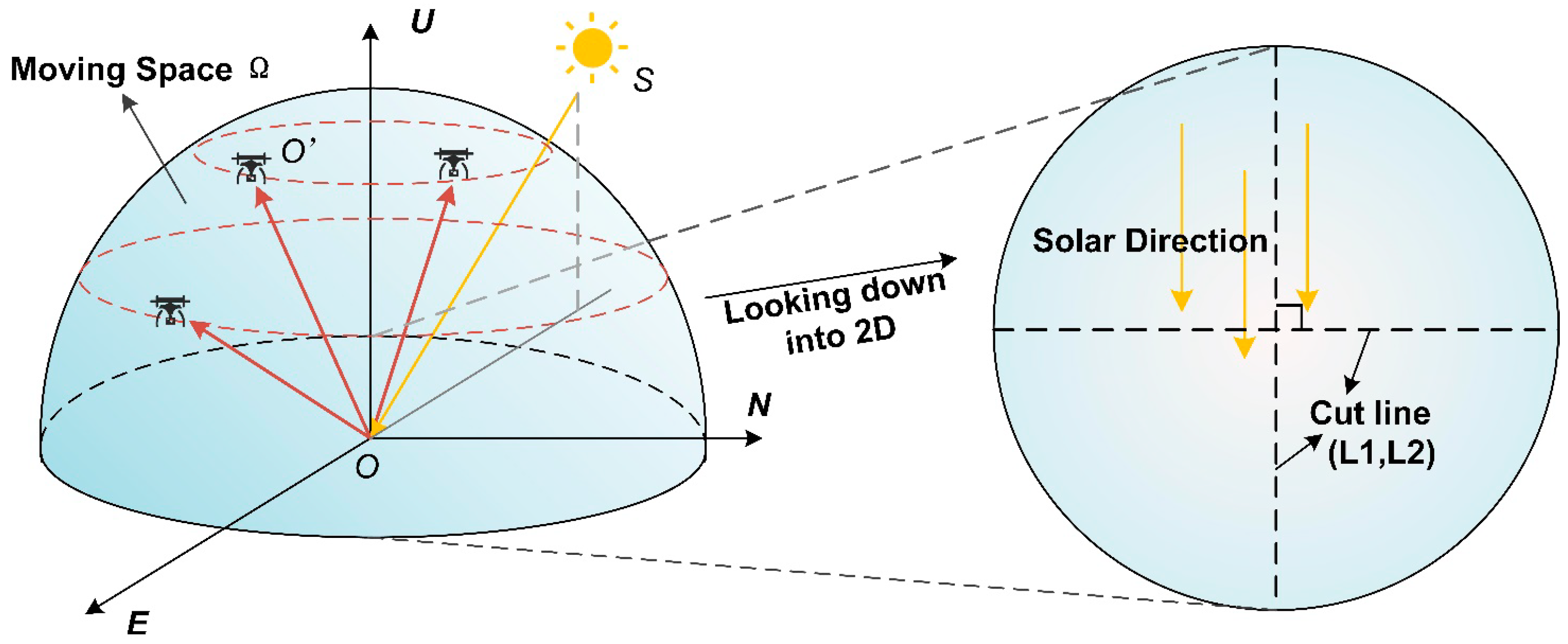
Figure 4. The position of the sun is marked as point S, and it does not deviate significantly in a short period. Sunlight propagates along the direction of SO, radiates outward at the measurement point O, and is finally received by the laser at position O′. Therefore, for the propagation optical path SOO′, the directions of the sun’s position and the laser’s position can be denoted as OS and OO′, respectively. Under elliptical orbit scanning, the receiving direction of the laser constantly changes. Ideally, all possible positions and receiving directions of the laser can be simplified and described by a hemispherical space Ω, and O′ is also a point on the spherical surface. By simply traversing the receiving directions of the laser within the entire space, the top view on the right side of
Figure 4 can be obtained, which allows for a more intuitive view of all the receiving directions. The cross-section line on the right side of
Figure 4 is used to better compare the model differences at different receiving positions.
As can be seen from Equation (9), the position of the sun can be represented by the solar zenith angle and the solar azimuth angle. Different combinations of solar zenith angles and solar azimuth angles will have varying degrees of influence on the model results.
Figure 5A illustrates the spatial distribution characteristics of the noise rate calculated by the BNR-B model under different solar azimuth angles. In the experiment, the solar zenith angle was fixed at 20°, and the solar azimuth angle was sampled in all circumferential directions (from 0° to 360°) at intervals of 24°. The color in the figure is mapped to the intensity of the noise rate, and the X-Y coordinates represent the projection components of the laser receiving direction in the hemispherical coordinate system. The results show that the change in the solar azimuth angle only leads to the rigid rotation of the noise distribution pattern, while the numerical magnitude and the distribution morphology are exactly the same, verifying the rotational symmetry of the model in the horizontal plane. This characteristic indicates that the calculation results of any azimuth can be mapped to the reference azimuth (such as 0°) through a rotation transformation, and the model itself is not substantially affected by the change in the azimuth angle.
To quantify the coupling effect of the azimuth angle and the zenith angle, as shown in
Figure 4, two orthogonal cross-section lines were extracted: the main-plane cross-section line L1, consistent with the solar azimuth; and the orthogonal-plane cross-section line L2, perpendicular to it.
Figure 5C shows the analysis results of the cross-section lines when the solar zenith angle is 20° and the azimuth angles are 0°, 24°, 48°, and 72°. The key findings are as follows. (1) Independence of the azimuth angle: When the solar azimuth is used as a fixed reference system, the results of different azimuth angles in the L1 and L2 cross-section lines completely coincide, confirming that the change in the azimuth angle only changes the observation perspective, rather than the numerical distribution of the noise field. (2) Spatial heterogeneity: Although the noise field is generally rotationally symmetric, the significant differences between the L1 and L2 cross-section lines reveal the non-uniformity of the hemispherical reflection field. This heterogeneity stems from the directional sensitivity of the BRDF model to the incident receiving geometry.
During dynamic flight, the real-time changes in the relative position between the laser receiving direction and the sun (such as the deflection of the flight trajectory) will break the theoretical assumption of rotational symmetry. For example, even if the position of the sun is fixed, attitude disturbance or heading adjustment of the UAV platform will still change the spatial coupling pattern of the noise rate. Therefore, optimizing the design of the flight trajectory to avoid high-noise coupling areas is the key to improving the robustness of the system.
As shown in
Figure 5B, the BNR-B (Background Noise Rate based on BRDF) model was evaluated under different solar zenith angles (from 0° to 90°) with the solar azimuth angle fixed at 180°. Since the model is still dominated by specular reflection, changes in the zenith angle directly adjust the incident geometry of solar noise photons, resulting in significant changes in the noise distribution pattern. When the zenith angle is small (the sun is close to the zenith), the noise rate exhibits approximately concentric circular symmetry. As the zenith angle increases (the sun approaches the horizon), the incident angle decreases, and the energy concentrates near the specular reflection direction.
Two orthogonal cross-sections were extracted from the hemispherical noise field, namely, the L1 solar principal plane and the L2 orthogonal plane, as shown in
Figure 5D. The main observations are as follows: For the L1 cross-section (the principal plane), as the zenith angle increases, the peak position moves outward, which is consistent with the specular reflection geometry. At high zenith angles (>48°), except for some outliers, most of the noise rates drop to a low-intensity stable state, which reflects that the directional sensitivity is suppressed under grazing illumination conditions. For the L2 cross-section (the orthogonal plane), the peak position remains stable under different zenith angles, but the peak magnitude drops sharply from 28.64 kHz (at a zenith angle of 0°) to 4.60 kHz (at a zenith angle of 72°), indicating that the off-specular scattering decreases under oblique incidence.
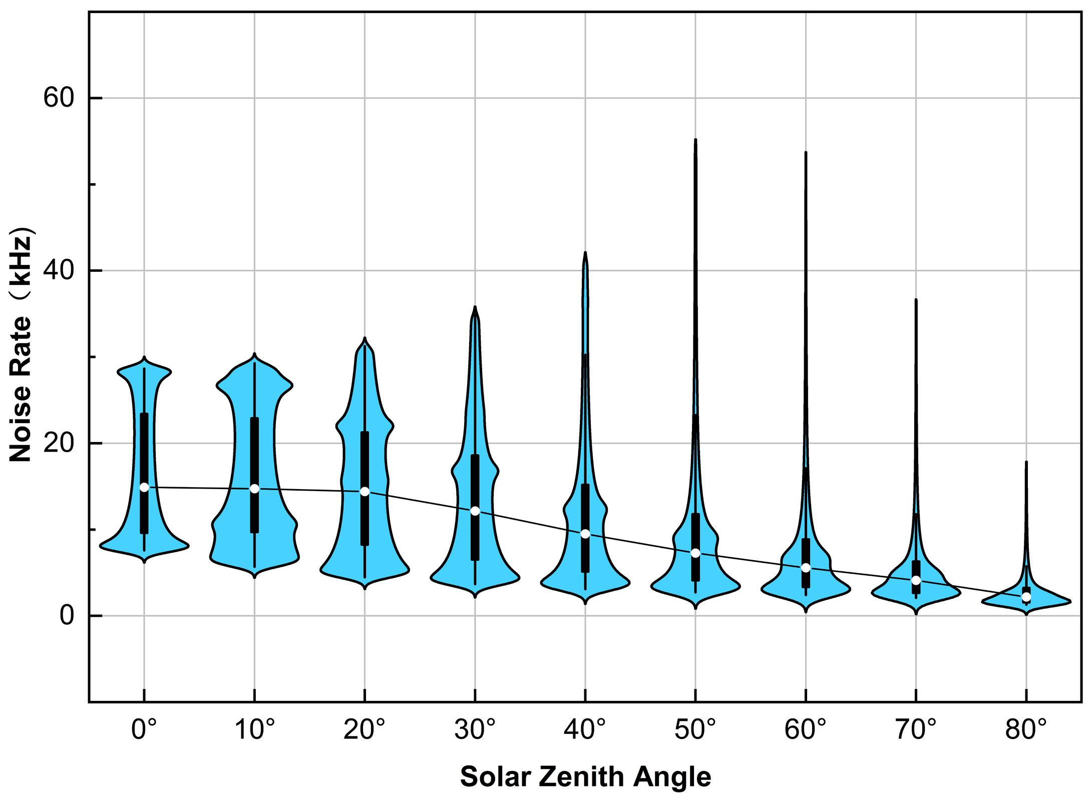
To further analyze the impact of the zenith angle on the noise rate distribution, the violin plots in
Figure 6 statistically quantify the dependence of the noise rate on the zenith angle across the entire hemispherical field (zenith angles from 0° to 80°). The results show the following: (1) Affected by the weakening of the specular reflection intensity, the median noise rate (black curve) continuously decreases as the zenith angle increases. It is fitted according to the Gaussian formula as
(
= zenith angle);
. (2) As the zenith angle increases, the noise rates concentrate within a narrower range (the interquartile range is reduced by 68%), and the long tails indicate the existence of residual specular reflection hotspots. (3) When the zenith angle is greater than 60°, the spatial heterogeneity decreases, indicating the emergence of a quasi-uniform noise field, in which the noise levels in most directions are similar. This also means that the zenith angle determines the trade-off between noise intensity and directional uniformity. At low zenith angles (the sun is close to the zenith), high-intensity noise concentrates in the specular reflection region, which requires trajectory planning to avoid critical angles. At high zenith angles (the sun is close to the horizon), the uniform low-intensity noise simplifies the system calibration process, but it requires higher detector sensitivity.
These research results emphasize the importance of understanding the solar geometry for optimizing the operation of airborne LiDAR in coastal or mountainous terrains under dynamic lighting conditions.
3.1.2. Results of the Change in Medium Properties
In addition to the spatial-position-related parameters mentioned in
Section 3.1.1, the medium itself also plays a role in determining the characteristics of the reflection cross-section during the bidirectional reflection process. Different medium properties may greatly affect the intensity of forward or backward scattering. In the current model, the medium properties are mainly characterized by the Fresnel reflectance and surface roughness parameters. Fresnel reflection refers to the change in reflectance when light is incident on the object surface at different angles [
24]. The reflectance used here corresponds to the case when the light is incident vertically on the medium surface. Surface roughness is generally used to describe the undulation characteristics or smoothness of the medium surface. The specific roughness is related to properties such as surface disturbances, cracks, and particle sizes.
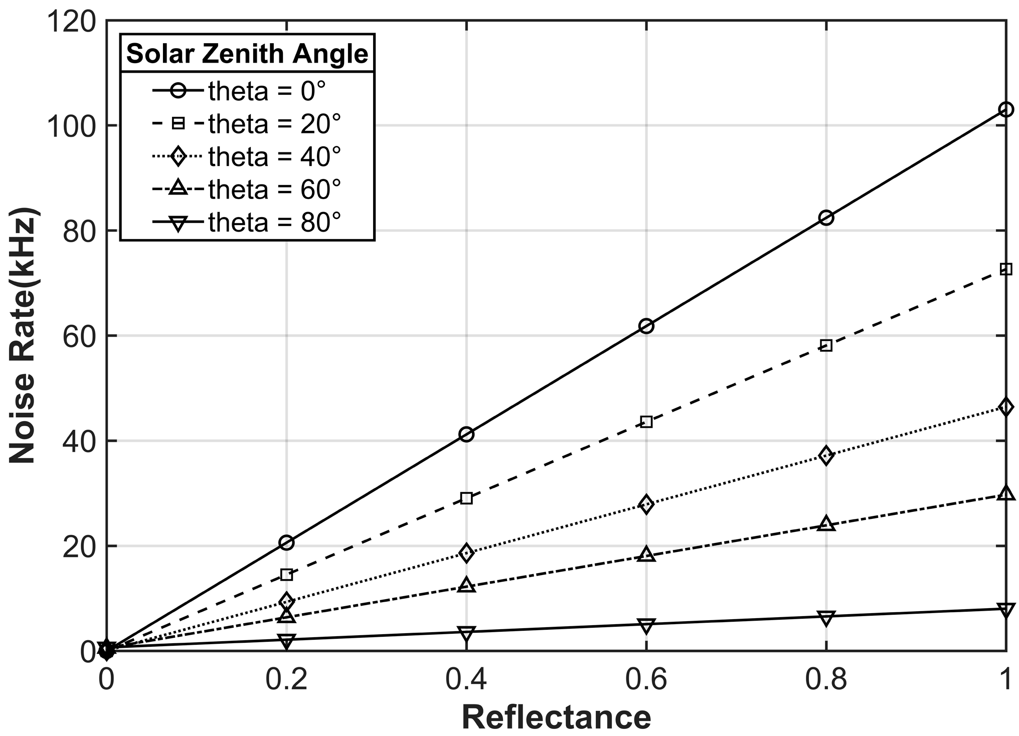
Figure 7 shows the linear relationship between the noise rate and the surface reflectance (ranging from 0 to 1) under five solar zenith angles (0°, 20°, 40°, 60°, 80°). To eliminate the directional bias and isolate the effect of reflectance, the noise rate for each configuration is represented by the hemispherical field-averaged value. As shown in the figure, all curves exhibit a linear increase with an increase in reflectance (
> 0.99), which confirms that the reflectance is a major limiting factor of the background noise. The magnitudes of the slopes (103.00, 72.66, 46.46, 29.75, and 8.05 for the five solar zenith angles from 0° to 80°, respectively) decay exponentially with the increase in the zenith angle. The equation can be derived as
(
= zenith angle);
. This trend is consistent with the specular reflection-dominated energy redistribution; that is, smaller zenith angles enhance the sensitivity to reflectance by distributing photons over a wider angular range. However, when the zenith angle is 80°, the slope drops to 7.8% of that when the zenith angle is 0°, which reflects that the energy is severely restricted near the specular reflection direction. Therefore, under grazing illumination conditions, the change in reflectance has a minimal impact on the overall noise rate. In addition, the stable linear relationship (residual standard deviation
) enables the direct implementation of reflectance normalization in the noise correction process, especially applicable to nadir observations or cases with small zenith angles.
The deterministic coupling relationship between reflectance and noise simplifies the system-level error budgeting. For high-reflectance surfaces, due to the large slope of noise growth with reflectance, the dynamic range needs to be prioritized. While for low-reflectance surfaces, the detector sensitivity needs to be optimized to resolve weak signals against the background of residual noise.
Unlike the change characteristics of reflectance, the influence of roughness on the model is more random. Taking the Cook–Torrance model in this paper, the rough reflective surface of the medium can be regarded as composed of numerous micro-facets, and each micro-facet can be considered as an ideal specular reflector. Thus, during the simulation, the micro-facet distribution function describes the rough undulations of the medium surface, meaning that different medium surfaces can be characterized by different micro-facet distributions.
In an absolutely ideal smooth mirror environment, after a point light source is reflected the energy will only concentrate in the mirror image direction. The small-scale interface undulations described by roughness affect the radiation intensity and range of energy. When the roughness increases, the distribution of micro-surfaces in different directions will also have significant differences, which directly affects the reflection characteristics of the entire reflection cross-section. Generally speaking, only when the interface is rough will a small part of the energy be radiated to the area outside the vertical plane where the light source direction is located. To highlight the contribution of roughness to the model, an additional set of experiments is designed in this section, mainly to observe the variation law of the model within the vertical plane where the light source direction is located. As shown in
Figure 4, assuming that the sun is fixed in a certain azimuth, the receivable direction of the laser is still a hemisphere composed of arbitrary directions in space. A vertical cross-section passing through the sun direction and perpendicular to the NOE plane is taken. At this time, the receivable direction of the laser changes from a hemisphere to a semi-circular arc, and the zenith angle varies within the range of 0 to 90°. Considering the angle between the receiving direction and the horizontal plane, taking the side where the sun is located as 0, the laser receiving angle can be transformed and recorded as
changing from 0° to 180°. Regarding
as the polar angle and calculating the model result in each direction as the polar radius, the final polar coordinate graph is shown in
Figure 8.
To more intuitively observe the influence of different medium roughnesses, we selected 10 groups of roughness values within the range of 0–1 for calculation, basically covering common media such as water surfaces, sand, and land surfaces. The solar light source is placed at zenith angles of 0° and 30°, with “m” representing different roughness levels. The results are shown in
Figure 8A,B. Considering that the change in the solar azimuth angle mentioned in
Section 3.1.1 does not cause numerical differences, the solar azimuth angle is selected as 0° here. That is, the cross-section studied in this experiment is the plane where the solar azimuth angles of 0° and 180° are located. It can be seen from the figure that the change in the solar zenith angle does not affect the law dominated by specular reflection; that is, the energy mainly concentrates near the mirror image direction. As the solar zenith angle moves, the direction of the model result also changes accordingly. It is worth noting that this directivity is greatly weakened after the roughness exceeds a certain level. The roughness regulates the scattering direction of the micro-surfaces through the normal distribution function (NDF). When the roughness increases from 0 (specular surface) to 1 (diffuse surface), the energy is dispersed from the specular direction to a wider angular range, resulting in a decrease in the spatial heterogeneity of the noise field. Taking
Figure 8A as an example, as the roughness increases, the influence of the micro-surfaces parallel to the medium plane on the distribution function gradually decreases, and more energy is radiated and dispersed to a larger area outside the vertical plane. So, intuitively, the model result seems to contract inward in a concentric structure. However, it can actually be seen that this contraction law will change to outward expansion when the laser zenith angle exceeds 84 degrees. This is because under the current model assumptions, the model result is determined by multiple parameters, especially the parameter term in the denominator related to the angle between the laser receiving direction and the normal direction. When the laser zenith angle is large, this angle is close to 90 degrees, and its cosine value is close to 0, which leads to a certain tendency for the model result to extend outward when the laser zenith angle is large. But obviously, this belongs to the internal characteristics of the model itself and does not affect the overall regular results. In
Figure 8B, when the position of the sun is at the marked position of 60 degrees, the energy is mainly concentrated near the mirror image direction of 120 degrees, and the peak direction is 120 degrees. This also indicates that significant instantaneous high-intensity noise will be generated when the receiving direction of the laser coincides with the reflection direction of the sunlight. For example, when the roughness is at a relatively small value of 0.2, the noise rate can reach up to 142 kHz. It is worth noting that in an absolutely ideal situation, all the energy should be radiated in the form of forward scattering. However, due to the increase in roughness, while the overall result contracts inward, the center of gravity of scattering also shifts, manifested as a gradual weakening of forward scattering and a gradual strengthening of backward scattering. This means that under the dominance of roughness, completely different scattering characteristics can be obtained, which is also an important influencing factor in the model.
In conclusion, the background noise model established based on the BRDF reveals that the solar zenith angle dominates the noise intensity, while medium properties such as roughness regulate the scattering directionality. It provides interpretable results that conform to objective real-world laws for different scenarios, comprehensively helping us understand the action process of solar background noise. At the same time, the model is highly sensitive to parameter changes, which means it can cover most operation scenarios. However, its practical application still needs to be further verified in the future.
