Article

A Distributed Low-Degree-of-Freedom Aerial Target Localization Method Based on Hybrid Measurements

1
Xi’an Institute of Space Radio Technology, Xi’an 710100, China
2
National Key Laboratory of Science and Technology on Space Microwave, Xi’an 710100, China
3
School of Information Science and Technology, Northwest University, Xi’an 710127, China
*
Author to whom correspondence should be addressed.
These authors contributed equally to this work.
Remote Sens. 2025, 17(10), 1705; https://doi.org/10.3390/rs17101705
Submission received: 7 February 2025 / Revised: 5 May 2025 / Accepted: 7 May 2025 / Published: 13 May 2025

Abstract

:
For real-time detection scenarios such as battlefield reconnaissance and surveillance, where high positioning accuracy is required and receiving station resources are limited, we propose an innovative distributed aerial target localization method with low degrees of freedom. This method is based on a hybrid measurement approach. First, a measurement model is established using the spatial geometric relationship between the distributed node network configuration and the target, with angle of arrival (AOA) and time difference of arrival (TDOA) measurements employed to estimate partial target parameters. Then, frequency difference of arrival (FDOA) measurements are utilized to enhance the accuracy of parameter estimation. Finally, using inter-node measurements, a pseudo-linear system of equations is constructed to complete the three-node aerial target localization. The method uses satellites as radiation sources to transmit signals, with unmanned aerial vehicles (UAVs) acting as receiving station nodes to capture the signals. It effectively utilizes hybrid measurement information, enabling aerial target localization with only three receiving stations. Simulation results validate the significant advantages of the proposed algorithm in enhancing localization accuracy, reducing system costs, and optimizing resource allocation. This technology not only provides an efficient and practical localization solution for battlefield reconnaissance and surveillance systems but also offers robust technical support and broad application prospects for the future development of unmanned systems, intelligent surveillance, and emergency rescue.

1. Introduction

With the continuous development of distributed radar systems, high-precision target localization in multi-station radar has become one of their unique advantages. The core of target localization lies in utilizing multi-angle observations from different receiving stations to fully exploit the system’s spatial diversity gain, thereby achieving higher localization accuracy. It is well known that under the condition of a fixed number of radars, the more dispersed the observation angles of the target, the greater the system’s spatial diversity gain and the higher the target localization accuracy. Conversely, if the target lies along the same observation direction of multiple radars, effective localization cannot be achieved. This technology has broad application prospects in military reconnaissance and precision strikes, as well as civilian fields such as communication, rescue, and traffic management [1,2,3]. However, the performance of distributed radar systems is constrained by the number of receiving stations and their geometric configuration. Particularly in real-time reconnaissance scenarios, where receiving stations serve as critical sensing resources, maintaining high-precision localization under station-limited conditions has become a key challenge.
Existing target localization methods can be categorized into active localization and passive localization [4]. Active localization refers to radar systems actively transmitting signals, which are reflected by the target and received by the radar. In this case, the signal source is controllable, forming a complete transceiver system [5]. However, the presence of the transmitting source reduces radar stealth and makes it susceptible to enemy electronic interference. In comparison, passive localization radar does not transmit signals; it only receives signals radiated by the target. While it offers good stealth, it cannot localize the target when the target’s radiation intensity is low [6]. To balance stealth and detection reliability, air–space cross-domain radar systems have emerged in recent years. These systems illuminate the mission area using high-orbit satellites and employ unmanned aerial vehicles (UAVs) as receiving stations, successfully achieving target localization while ensuring both stealth and detectability. This approach integrates the advantages of both active and passive localization to some extent, providing a new technological pathway for target detection and localization in complex environments. However, for multi-receiver distributed radar target localization, hardware resource limitations remain a significant challenge—conventional TDOA-based localization methods require at least four receiving stations to ensure parameter identifiability [7]. In a wartime environment, the number of receiver stations is a highly valuable sensing resource, making it necessary to study the target localization problem under given constraints on the number of receiver stations.
In the pursuit of overcoming hardware resource constraints, methodological innovations in signal processing and optimizations in system architecture are equally important. At the algorithmic level, target localization methods can be further categorized into direct localization and indirect localization [8]. Direct localization methods refer to directly combining target signals from multiple receiving stations to estimate the target’s localization at the signal level. If multiple radars observe the target from approximately the same viewing angle, the coherent processing of signals can be performed utilizing phase information to locate the target, thereby significantly improving positioning accuracy. In direct localization methods, the target’s localization can be determined through multidimensional search or optimization relaxation techniques. However, multidimensional search methods face challenges such as phase ambiguity and high computational cost, while optimization relaxation methods require parameter tuning and involve a trade-off between convex relaxation approximation and localization accuracy [9]. As the name suggests, indirect localization methods first extract indirect measurements from the signals, such as distance, Doppler, angle, etc., and then perform measurement-level localization based on the extracted measurements. Because indirect localization methods isolate the localization process and can provide a closed-form solution for the target’s position, they have become mainstream methods in research [10,11,12,13,14].
In indirect localization methods, parameter identifiability is a key factor in ensuring target localizability. For the three-dimensional aerial target localization problem, excluding ill-conditioned observation configurations, TDOA localization requires at least four stations, and the use of differentiation will incur the additional consumption of one common receiver station [15,16,17,18,19,20,21]. In practical applications, target localization is closely related to factors such as the number of radar stations, the radar target geometry, and the signal-to-noise ratio (SNR). Therefore, to meet localization accuracy requirements under limited receiving station resources, it is necessary to jointly optimize these factors along with radar system parameters [22,23,24,25,26,27,28,29,30,31].
For the parameter estimation problem in TDOA localization, Chan and Ho proposed a classic two-stage ellipsoid localization estimation method [32]. In the first stage of this method, the reference distance (the distance from the reference radar to the target) is combined with the target localization to form an augmented parameter vector. The augmented parameter vector is then estimated by linearizing the nonlinear equations. In the second stage, based on the relationship between reference distances and target positions, the target position estimate is updated to improve localization accuracy. Furthermore, in 2023, Zou and Fan proposed a new hybrid AOA and TDOA localization algorithm [33], which incorporates AOA measurements into the TDOA measurements, thereby reducing the highest order of the noise term product to the second order. By reducing the number of neglected noise terms, the algorithm’s performance is improved. The advantage of these methods lies in their ability to effectively reduce the computational complexity of nonlinear solutions. However, they assume that the positions of the receiving stations are accurately known, without considering the impact of receiving station position errors on localization accuracy.
To overcome this limitation, at the 2004 ISCAS conference, Ho and Parikh modified this method into an iterative form, making it applicable to situations where there are position errors in the receiver stations [34]. Under conditions where the position errors of the receiver stations are small, the method can approach the Cramér–Rao lower bound for parameter estimation, achieving near-optimal parameter estimation. However, when the position errors are larger, the introduction of nonlinearity leads to a decrease in localization accuracy. To mitigate this issue, researchers have attempted to replace the original update strategy with a first-order Taylor approximation technique in the second stage, resulting in some accuracy improvement. However, such methods introduce the reference distance into the augmented parameter vector, which requires at least five receiver stations to satisfy the parameter identifiability condition.
To reduce the number of receiving stations, subsequent researchers proposed an improved strategy, which involves pre-substituting the estimated reference distances into the augmented parameter vector, thereby reducing the number of free parameters and lowering the requirement for the number of receiving stations. On this basis, Chen’s team [35] conducted an in-depth study on the inherent relationship between distributed configurations and hybrid measurements, proposing an airborne target localization method based on four receiving stations. This method fully leverages the hybrid measurement information, reducing the dependency of parameter identifiability on the number of receiving stations. This ensures localization accuracy while minimizing the consumption of system perception resources. This research provides an effective solution for high-accuracy airborne target localization under limited receiving station conditions.
Although the aforementioned method can reduce the number of receiver stations required for TDOA localization to a minimum of four, receiver stations are a highly valuable resource for real-time reconnaissance and surveillance [36,37,38,39,40,41]. Under the allowed conditions, we aim to achieve the localization accuracy requirements with the fewest possible receiver stations, even if it means accepting a certain degree of accuracy loss in exchange for reducing the number of stations. Therefore, this paper proposes a distributed low-degree-of-freedom airborne target localization method based on hybrid measurements. This method fully utilizes various measurement data both within and between radar stations and estimates the reference distances and the target’s X-coordinate within the station, enabling the estimation of the remaining parameters to be completed with only three receiving stations. Compared to traditional methods, this approach effectively reduces the number of receiving stations while still meeting localization accuracy requirements, demonstrating significant engineering application value and showing broad prospects in fields such as unmanned systems, intelligent monitoring, and emergency rescue.
In recent years, there has been continuous progress in enhancing the localization performance of distributed airborne radar systems. For instance, Li et al. [42] proposed an improved planar approximation algorithm that accounts for platform position uncertainty and achieves high localization accuracy via iterative refinement. Xu et al. [43] addressed trajectory-induced errors in SAR systems with a closed-loop structure to correct motion discrepancies. Additionally, Niu et al. [44] presented a high-frame-rate imaging framework that significantly improves moving target detection performance under very-low-SNR conditions. These works offer valuable technical references and comparison baselines for the method proposed in this paper.
The remaining parts are outlined as follows. In Section 2, the measurement model used in the proposed method is introduced, and a detailed description of the distributed low-degree-of-freedom aerial target localization method based on hybrid measurements is provided. In Section 3, the experimental data are presented, along with a comprehensive analysis of the results. In Section 4, a detailed comparative discussion is provided, where the proposed method is evaluated against other existing approaches in terms of accuracy and efficiency. Finally, we draw a brief conclusion in Section 5.
The mathematical symbols used in this paper are summarized in Table 1:

2. Materials and Methods

2.1. Measurement Model

Assume that the space-to-air distributed radar network consists of a single high-orbit satellite-mounted radar and several unmanned aerial vehicle (UAV)-mounted radars. The high-orbit satellite radar emits signals, while the UAV-mounted radars only receive the signals. Figure 1 shows a schematic diagram of the measurement model. To focus on three-station target localization, it is assumed that the number of receiving radars is K = 3 . The satellite navigation position is located at a o = [ x a o , y a o , z a o ] T . Considering that the positioning accuracy of GNSS is limited, the relationship between the actual satellite position a and the navigation position a o can be described as a = a o + Δ a = [ x a , y a , z a ] T . In the equation, Δ a represents the satellite navigation position error, and v a represents the satellite velocity. Similarly, the navigation position of the i-th UAV is located at s i o = [ x i o , y i o , z i o ] T , i = 1 , 2 , , K . The relationship between the actual position s i and the navigation position s i o is given by s i = s i o + Δ s i = [ x i , y i , z i ] T . In the equation, Δ s i represents the position error of the i-th UAV, and the UAV velocity is v s . The definitions of intra-station and inter-station measurements are provided below.

2.1.1. Intra-Station Measurements

Intra-station measurements primarily refer to the angle of arrival (AOA) measurements obtained from the antenna array within the receiving radar [45]. Assuming that the aerial target is located at u = [ x , y , z ] T , the true reception cone angle observed by the i-th UAV is
φ i = arccos u s i T e 1 u s i 2
In the equation, e 1 = [ 1 , 0 , 0 ] T . Due to the limited angular measurement accuracy, the true reception cone angle φ i is subject to measurement noise. The AOA measurement can be expressed as follows:
φ ˜ i = φ i + Δ φ i
where Δ φ i represents the AOA measurement noise.

2.1.2. Inter-Station Measurements

Inter-station measurements primarily refer to the time difference of arrival (TDOA) [46] and frequency difference of arrival (FDOA) measurements [47] obtained through differencing between the receiving stations and the reference station.
First, the true bistatic range received by the i-th UAV after the signal is transmitted from the high-orbit satellite and passes through the target can be expressed as follows:
b i = u a 2 + u s i 2
After performing range differencing, the differential range can be represented as
r i 1 = b i b 1 = r i r 1
In the equation, r i = u s i 2 represents the distance from the target to the i-th UAV. Considering that the TDOA and RDOA measurements differ only by a multiplicative factor, the two types of measurements are not strictly distinguished in the following. Thus, the TDOA measurement can be expressed as
r ˜ i 1 = r i 1 + c Δ t i 1
where c represents the speed of light, and Δ t i 1 denotes the differential time delay measurement noise.
Similarly, the true bistatic Doppler shift is given by
f d i = v a + v t λ cos ψ T + v s + v t λ cos ψ R i
where v t represents the instantaneous velocity of the target, and λ is the wavelength.
cos ψ T = u a T e 1 u a 2 , cos ψ R i = u s i T e 1 u s i 2
These are the transmitter and receiver velocity cone angles, and after Doppler differencing, the true bistatic Doppler shift is given by
f d i 1 = f d i f d 1
Similarly, the FDOA measurement can be expressed as
f ˜ d i 1 = f d i 1 + Δ f d i 1
where Δ f d i 1 represents the FDOA measurement noise.

2.2. Proposed Method

In this section, we propose a three-station hybrid target localization method. A flowchart of the proposed distributed low-degree-of-freedom aerial target localization method based on hybrid measurements is presented in Figure 2. First, the method estimates the reference distance and the target’s X-coordinate jointly using AOA and TDOA measurements. Subsequently, FDOA measurements are employed to assist in improving the accuracy of parameter estimation. Finally, by combining the estimated target parameters and using a ‘compressed’ parameter approach, the target is localized by constructing pseudo-linear equations using inter-station TDOA measurements. The proposed method effectively utilizes a hybrid of intra-station and inter-station measurements, enabling target localization with only three receiving stations. The specific implementation scheme is described as follows.

2.2.1. Intra-Station and Inter-Station Hybrid Measurements for Estimating the X-Coordinate and Reference Distance

Considering that the positional errors of the radar have a negligible impact on the observation angle, that is
φ i φ i o acos x x i o r i
and r i = r i 1 + r 1 , we obtain
x r 1 cos φ i = x i o + r i 1 cos φ i
We define the parameter vector v 1 [ x , r 1 ] T and organize the measurements from all receiving radars in matrix form, which can be expressed as
h a = G a v 1
where
G a = 1 cos φ 1 1 cos φ 2 1 cos φ 3
and
h a = x 1 o x 2 o x 3 o + 0 r 21 cos φ 2 r 31 cos φ 3
By replacing the noise-free measurement vectors φ ˜ = [ φ ˜ 1 , φ ˜ 2 , φ ˜ 3 ] T and r ˜ 1 = [ r ˜ 21 , r ˜ 31 ] T with the noisy measurement vectors φ = [ φ 1 , φ 2 , φ 3 ] T and r 1 = [ r 21 , r 31 ] T , the least squares (LS) problem can be formulated as
v ^ 1 = min v 1 h a G a v 1 2 2
the LS solution is
v ^ 1 = G a T G a 1 G a T h a
However, in AOA and TDOA measurement methods, the accuracy of parameter estimation is constrained by multiple coupled error effects: the high sensitivity of AOA measurements to array calibration errors leads to minor angular deviations being nonlinearly amplified in long-range scenarios, whereas TDOA is subject to the precision of inter-base station clock synchronization, introducing systematic biases in range estimation. Additionally, the geometric configuration may restrict observability in certain directions. Moreover, both AOA and TDOA are static measurements, making it impossible to distinguish time delay variations caused by target motion from actual position shifts. Due to the non-uniform error propagation characteristics of coordinate transformations, azimuth errors predominantly contribute to radial localization deviations in far-field conditions, while time difference errors play a major role in near-field environments, resulting in a complex spatial error distribution pattern.

2.2.2. Enhancing Parameter Estimation Accuracy with FDOA Measurements

To address the aforementioned error propagation characteristics and system limitations, FDOA observations are introduced to reconstruct an optimized parameter estimation framework by incorporating dynamic information from Doppler shifts. The relative velocity information contained in FDOA measurements provides an observational gradient direction that is spatially orthogonal and complementary to the geometric measurements of AOA/TDOA, effectively mitigating the loss of height observability in coplanar layouts. Meanwhile, the sensitivity of Doppler effects to velocity parameters enables the decoupling of position and time delay parameters, thereby suppressing the accumulation of higher-order errors. From an error statistics perspective, FDOA is independent of the error distribution patterns of geometric measurements (i.e., frequency shift errors and angular/time difference errors exhibit uncorrelated statistical properties), allowing information fusion to reduce estimation variance. Additionally, the temporal differentiation characteristic of dynamic observations enables the identification and separation of systematic biases in AOA/TDOA (such as clock drift or array deformation errors), achieving cross-domain error compensation. From an information-theoretic standpoint, FDOA expands the dimensionality of the observation space, fundamentally lowering the theoretical minimum error bound. This not only surpasses the accuracy constraints imposed by the Cramér–Rao bound for purely static observation systems but also establishes a temporal smoothing mechanism through motion continuity constraints, ultimately forming an estimation framework that enhances accuracy via geometric–dynamic multidimensional information fusion.
The FDOA measurement between the i-th receiving radar and the reference radar can be expressed as
f d i 1 = v s + v t λ cos ψ R i cos ψ R 1
on the other hand, for a side-looking array, the velocity cone angle and the array face cone angle are equal, i.e., ψ R i = φ i . Therefore, due to the presence of the common term ( v s + v t ) / λ , the FDOA measurements can be constrained as:
f d 21 cos φ 2 cos φ 1 = f d 31 cos φ 3 cos φ 1
it follows that
f d 31 cos φ 2 x x 1 o r 1 = f d 21 cos φ 3 x x 1 o r 1
that is
x r 1 f d 21 cos φ 3 f d 21 cos φ 2 f d 21 f d 31 = x 1 o
Rearranging Equations (11) and (20) into matrix form, we obtain
h a = G a v 1
In the equation, the value of G a is revised to
G a = 1 f d 21 cos φ 3 f d 21 cos φ 2 / f d 21 f d 31 1 cos φ 2 1 cos φ 3
and
h a = x 1 o x 2 o x 3 o + 0 r 21 cos φ 2 r 31 cos φ 3
In contrast to Section 2.2.1, Section 2.2.2 introduces the FDOA measurement equation while eliminating the need for the target AOA measurement from the reference station. It is important to emphasize that the Doppler estimation accuracy must be sufficiently high to effectively use FDOA measurements to assist in parameter estimation.

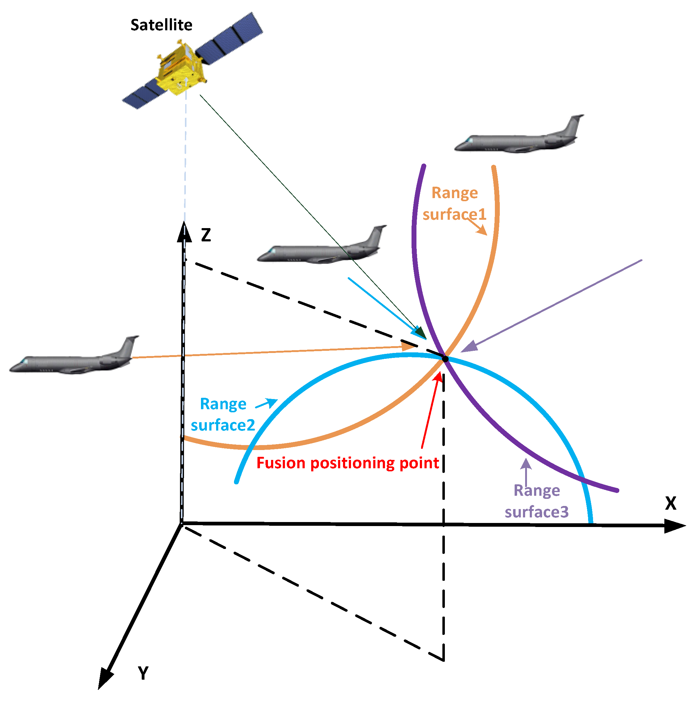
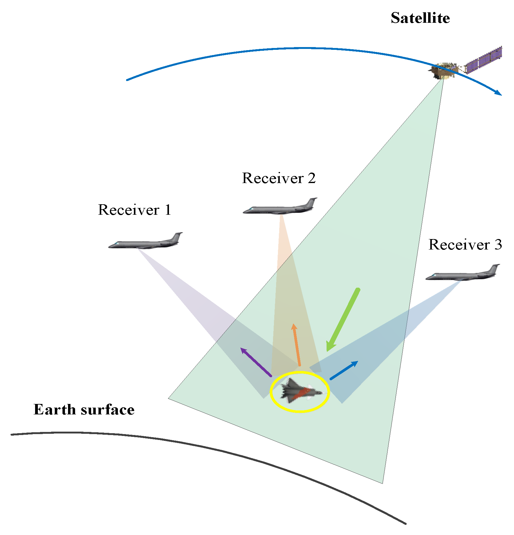
2.2.3. Utilizing Inter-Station Measurements to Achieve Three-Station Target Localization

A pseudo-linear equation set is constructed using inter-station TDOA measurements to localize the target. In the classical WLS-Ho method, by incorporating the reference distance into the vector of parameters to be estimated, aerial target localization involves four unknown parameters. Therefore, at least five receiving stations are required to satisfy the identifiability condition for parameter estimation. In this method, we estimate the reference distance and the X-coordinate of the target using a combination of intra-station and inter-station measurements. The two remaining unknown parameters reduce the requirement for the number of receiving stations to a minimum of three. By rearranging the equation r i 1 = r i r 1 as r i 1 + r 1 = r i and squaring both sides, we obtain
r i 1 2 + 2 r i 1 r 1 = R i R 1 2 s i s 1 T u
where R i = s i T s i .
Considering the noisy measurements r i 1 = r ˜ i 1 c Δ t i 1 and s i = s i o + Δ s i and substituting them into Equation (24), we obtain the following expression:
ς i 1 2 c Δ t i 1 r 1 o 2 s i o u T Δ s i + 2 s 1 o u T Δ s 1 r ˜ i 1 2 S ¯ i + S ¯ 1 + 2 s i o s 1 o T u + 2 r ˜ i 1 r 1 o
where r i o = u s i o 2 and S ¯ i = s i o T s i o . The TDOA measurements from all receiving stations are organized in matrix form as
ς = h b + 2 r ˜ 1 r ^ G b v 2
where ς = [ ς 21 , , ς K 1 ] T , v 2 = [ y , z ] T ,
h b = r 21 2 S ¯ 2 + S ¯ 1 r K 1 2 S ¯ K + S ¯ 1 + 2 x 2 o x 1 o x K o x 1 o x ^
and
G b = 2 y 2 o y 1 o z 2 o z 1 o y K o y 1 o z K o z 1 o
According to the Gauss–Markov theorem, by minimizing ς W ς , where W = E [ ς ς T ] 1 , the weighted least squares (WLS) estimate of v is obtained as
v ^ = G b T W G b 1 G b T W h b + 2 r ˜ 1 r ^ 1
In the equation, r ˜ = [ r ˜ 21 , , r ˜ K 1 ] T represents the TDOA vector. Considering that
ς = c A Δ t + B Δ s = A B c Δ t Δ s
where Δ t = [ Δ t 21 , , Δ t K 1 ] T and Δ s = [ Δ s 1 T , Δ s 2 T , , Δ s K T ] T ,
A I K 1
B 1 1 × 3 1 1 × 3 0 1 × 3 1 1 × 3 1 1 × 3 0 1 × 3 1 1 × 3
The weighted matrix W can be expressed as
W = A Q t A T + B Q s B T 1
where Q t = c 2 E [ Δ t Δ t T ] and Q s = E [ Δ s Δ s T ] .

2.2.4. Cramér–Rao Lower Bound
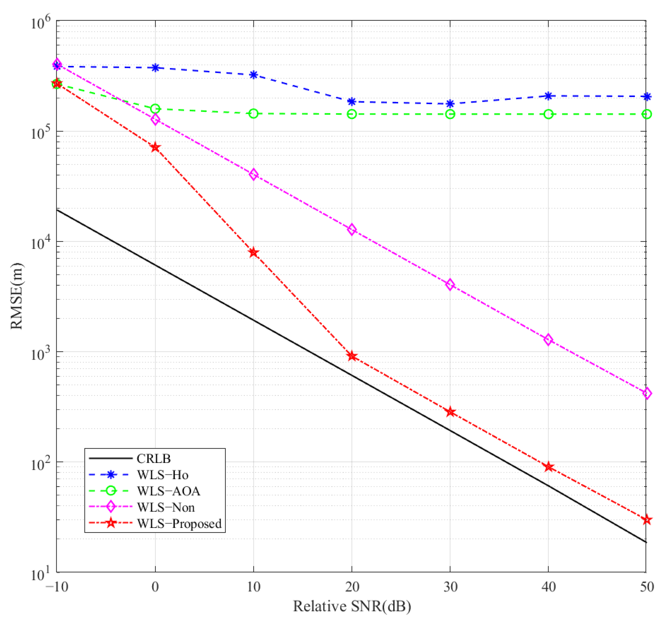
The CRLB is commonly used as a benchmark to place a lower bound of any unbiased estimator for the parameter of interest [48]. This section derives the Cramér–Rao lower bound (CRLB) for target localization estimation using TDOA and AOA measurements with three receiving stations to compare the target localization performance of different methods.
We assume that the TDOA measurement error Δ r 1 i and the AOA measurement error Δ ψ i follow a Gaussian distribution.
Δ r 1 i N 0 , σ Δ r 1 2
Δ ψ i N 0 , σ Δ ψ 2
where σ Δ r 1 2 and σ Δ ψ 2 represent the variances of the TDOA measurement error and the AOA measurement error, respectively, and the measurement errors between different receiving stations and different types are uncorrelated. This can be expressed as
E Δ r 1 i Δ r 1 i = 0 i , i = 2 , 3 ; i i
E Δ ψ j Δ ψ j = 0 j , j = 2 , 3 ; j j
E Δ r 1 i Δ ψ j = 0 i = 2 , 3 ; j = 1 , 2 , 3
We express the conditional probability density function of the measurement vector y = [ r 1 T , ψ T ] T in logarithmic form.
ln y u = 1 2 r 1 r ¯ 1 T Q Δ r 1 r 1 r ¯ 1 1 2 ψ ψ ¯ T Q Δ ψ ψ ψ 1 2 s s ¯ T Q Δ s 1 s s ¯ + C
where C is a constant.
Q Δ r 1 = σ Δ r 1 2 I 2
Q Δ ψ = σ Δ ψ 2 I 3
Q Δ s = I K 1 Q Δ s 0
According to its definition,
C R L B η = E 2 ln y η η η T 1
In the equation, η = [ u T , Δ s T ] T represents the parameter vector to be estimated. By substituting Equation (39) into Equation (43), we obtain
C R L B η = E 2 ln f y η η η T 1 = X Y Y T Z 1
where the block matrices X , Y , and Z can be expressed as
X = E 2 ln f y u u u T = y u T T Q Δ y 1 y u
Y = E 2 ln f y u u Δ s T = y u T T Q Δ y 1 y Δ s
Z = E 2 ln f y u Δ s Δ s T = y Δ s T T Q Δ y 1 y Δ s + Q Δ s 1
where
Q Δ y = Q Δ r 1 Q Δ ψ
for the covariance matrix of the measurement errors in the equation
y u T = r ¯ 1 u T ψ ¯ u T
r ¯ 1 u T = s 2 o u T d ¯ 2 s 1 o u T d ¯ 1 s 3 o u T d ¯ 3 s 1 o u T d ¯ 1 , ψ ¯ u T = w 1 2 d ¯ 1 2 x 1 o x y 1 o y w 1 d ¯ 1 2 x 1 o x z 1 o z w 1 d ¯ 1 2 w 2 2 d ¯ 2 2 x 2 o x y 2 o y w 2 d ¯ 2 2 x 2 o x z 2 o z w 2 d ¯ 2 2 w 3 2 d ¯ 3 2 x 3 o x y 3 o y w 3 d ¯ 3 2 x 3 o x z 3 o z w 3 d ¯ 3 2
y Δ s T = r ¯ 1 Δ s T ψ ¯ Δ s T
r ¯ 1 Δ s T = s 1 o u T d ¯ 1 s 2 o u T d ¯ 2 s 1 o u T d ¯ 1 s 3 o u T d ¯ 3 , r ¯ 1 Δ s T = ψ ¯ u T
For the Jacobian transformation matrix and its specific representation, we use the equation
w i = y y i 2 + z z i 2
According to the block matrix inversion lemma [49], we obtain
C R L B u = X 1 + X 1 Y Z Y T X 1 Y 1 Y T X 1
This is the Cramér–Rao lower bound for the target localization estimate.

3. Results

Consider an air–space distributed radar network with satellite transmission and UAV reception. Taking the sub-satellite point of the high-orbit satellite as the coordinate origin, the variance of the satellite’s position error is 100 m2. Three UAVs are located at [ 1 × 10 5 , 1 × 10 5 , 2.2 × 10 4 ] T m, [ 2 × 10 5 , 3 × 10 5 , 2.3 × 10 4 ] T m, [ 4 × 10 5 , 4 × 10 5 , 2.5 × 10 4 ] T m, with the variance of their position errors being 0.25 m2. The target localization measurement scenario is illustrated in Figure 3. Considering that the distances from the target to each receiving station vary resulting in different received SNRs, the relative SNR is defined as the received SNR relative to the reference radar. Each set of statistical results is obtained by averaging 2000 Monte Carlo simulations.
Furthermore, we have analyzed the constraints on the flight speed and spatial distribution of the three receiving stations. The flight speed of the receiving stations is constrained by the requirement that, within a coherent processing interval (CPI), the relative motion of the target with respect to the receiving array should induce an angular shift that is significantly smaller than the main lobe width of the array. Based on the analysis under the experimental conditions, the target-induced angular shift due to relative motion is much smaller than the receiving array’s main lobe width, thus meeting the coherent processing constraint.
The spatial distribution of the receiving stations is primarily determined by the geometric configuration of the system. To achieve robust localization and minimize positioning errors, the receiving stations should be arranged to form a spatially diverse baseline. A longer baseline improves resolution along the corresponding axis, while an optimized three-dimensional spatial layout enhances overall positioning accuracy. However, if the receiving stations are nearly coplanar, the vertical resolution will be significantly degraded, leading to increased errors in Z-axis estimation.
First, the target localization performance of different methods is evaluated in a single experiment. Table 2 presents the target localization results using the Ho method (WLS-Ho), the AOA-assisted localization method (WLS-AOA), the method without FDOA-assisted parameter estimation refinement (WLS-Non), and the hybrid measurement method (WLS-Update). Among these, WLS-AOA refers to estimating the target’s X-coordinate and reference distance using prior knowledge of the transmitted main beam and AOA rather than jointly using TDOA and AOA. Additionally, localization accuracy is defined as
σ u ( x x ^ ) 2 + ( y y ^ ) 2 + ( z z ^ ) 2
From Table 2, it can be observed that the localization accuracy of the WLS-Ho method and the WLS-AOA method is poor and lacks practical reference value. This is because the WLS-Ho method does not satisfy the identifiability condition for parameters and cannot achieve three-station TDOA target localization. On the other hand, the WLS-AOA localization method relies on prior knowledge of the main transmit beam. However, due to the broadness of the main transmit beam, using the transmission and reception angles along with a bistatic range to estimate the reference distance results in significant deviation, which leads to the target being located far from its actual position. The WLS-Non localization method first estimates partial target parameters using AOA/TDOA measurements, fills in the missing terms of the target identifiability condition, and then proceeds with the estimation of the remaining target parameters. The proposed hybrid localization method further incorporates FDOA measurements and utilizes the inter-station constraint relationships between FDOA measurements to improve the accuracy of target parameter estimation. Ultimately, the three-station target localization accuracy can be controlled within a few kilometers.
Figure 4 consists of four subfigures, where subfigure (d) presents the 3D scatter plot of the target position estimation using the proposed hybrid measurement method after 2000 experiments. Subfigures (a), (b), and (c) represent the projections of subfigure (d) onto the x-y, x-z, and y-z coordinate planes, respectively. The red pentagram represents the true target position, while the blue dots indicate the estimated positions for each experiment. It can be observed that the estimation deviations in the x, y, and z dimensions are approximately 100 m, 200 m, and 2000 m, respectively. In other words, the estimated target position is confined within a cube centered around the true target position, with dimensions of 200 m, 400 m, and 4000 m in length, width, and height, respectively. The errors in the target’s x-axis, y-axis, and z-axis are mainly influenced by the geometric layout of the three receiving stations in the spatial configuration. The baseline length in different directions affects the error in each axis; generally, the longer the baseline, the smaller the positioning error. The positions of the satellites and the spatial distribution of the UAVs directly impact positioning accuracy. From the experimental conditions, we can observe the spatial distribution of the three receiving stations. For the X and Y axes, the three receiving stations have relatively long baselines in the X and Y directions, meaning there is a significant coordinate difference between the UAVs along the X-axis, which helps reduce errors. For the Z-axis, the three receiving stations are distributed nearly in the same plane, resulting in insufficient vertical distribution and a lack of effective height differences, which leads to insufficient measurement information for the Z-axis and a significant increase in error. Additionally, the satellites, serving as radiation sources, are positioned above the receiving stations, restricting the geometric distribution of signals in the vertical direction. The distinction between a single target and two targets lies in whether their position measurement results overlap within the statistical error range. We can obtain the positioning error range by averaging the results of 2000 Monte Carlo simulations. In the case of a single target, all measurement data are distributed around a central point and do not form multiple clusters. If the true distance between two targets is greater than the positioning error, their measurement data will not overlap, allowing them to be identified as two separate targets. The 2000 experiments presented in this study were conducted through offline Monte Carlo simulations, primarily to verify the robustness and statistical characteristics of the proposed algorithm. The overall computational cost remained within an acceptable range. In practical applications, each positioning task corresponds to a single execution (i.e., one of the 2000 experiments), and the estimation is performed without multiple iterations, demonstrating good engineering feasibility.
Next, we will further analyze the impact of observing the target’s flight speed and altitude. The target’s speed is primarily observed through the frequency difference of arrival (FDOA). The FDOA is influenced by the relative motion between the target and the receiving stations. A higher speed results in a more significant Doppler shift, making it easier to distinguish moving targets from stationary clutter. However, for low-altitude targets, the motion of clutter may introduce additional interference, affecting the accuracy of speed estimation. Altitude estimation is mainly determined by the baseline distribution along the Z-axis. If the receiving stations are nearly positioned in the same horizontal plane, the vertical baseline is insufficient, leading to poor altitude resolution. This increases positioning errors along the Z-axis, making it difficult to distinguish low-altitude targets from ground clutter. A well-structured spatial distribution of receiving stations, including sufficient vertical separation, helps improve the accuracy of altitude estimation.
Figure 5 illustrates the effect of time synchronization errors on localization accuracy, as measured by RMSE. In this experiment, the SNR was set to 20 dB, and the influence of receiver position errors was also considered. Each data point represents the average result of 2000 Monte Carlo trials to ensure statistical reliability. The x-axis denotes the time error (in nanoseconds), while the y-axis shows the RMSE of the localization results (in meters). In the figure, the black horizontal line represents the CRLB (Cramér–Rao lower bound), which indicates the theoretical performance limit and remains constant since it is not affected by time errors. The green horizontal line (WLS-Proposed-T) represents the performance of the proposed method under ideal time synchronization. The purple curve (WLS-Proposed) shows the actual localization accuracy of the proposed method when time synchronization errors are introduced. As can be observed, with the time error increasing from 1 ns to 60 ns, the RMSE rises gradually from approximately 200 m to around 260 m. This relatively stable trend indicates that the proposed method exhibits a certain degree of robustness against time synchronization errors.
In summary, this figure not only validates the effectiveness of the proposed method under imperfect synchronization conditions but also quantitatively demonstrates the impact of such errors on localization performance. The results highlight the practical applicability and robustness of the proposed method in non-ideal synchronization environments.
Next, we present a comparison of the target localization performance of different methods in a statistical sense. Figure 6 illustrates the variation in the RMSE of the target localization estimation with respect to the relative SNR for different methods. It can be observed that the WLS-Ho method fails to meet the parameter identifiability conditions, while the WLS-AOA method relies on prior knowledge of the transmitted main beam. Due to the wide main beam, the reference distance estimated based on it exhibits significant bias. As the relative SNR increases, the RMSE of parameter estimation for both methods remains high, and the estimated target position deviates significantly from its true location. For the WLS-Non and WLS-Update methods, as the relative SNR increases, the RMSE of localization estimation gradually decreases. However, the estimation accuracy of the WLS-Non method still deviates from the Cramér–Rao lower bound (CRLB), whereas the WLS-Update method can approach the CRLB in regions with a high relative SNR. This indicates the effectiveness of introducing FDOA measurements to assist in estimating certain parameters.
Figure 6 also indirectly verifies the applicability of the first-order linearization modeling adopted in this paper. By analyzing the trend of localization RMSE versus relative SNR for different algorithms in a statistical sense, it confirms the suitability of this modeling approach under typical noise levels. The experimental results show that the WLS-Update method can approach the Cramér–Rao lower bound (CRLB) under medium-to-high-relative-SNR conditions, indicating that the first-order linear approximation used exhibits good robustness and convergence within this error range. To further address the issue of error propagation from initial parameter estimation, FDOA measurements are introduced in the second stage of the method design. From the perspective of information fusion, this effectively improves localization accuracy and mitigates the impact of modeling errors caused by linearization.
Additionally, we highlight the constraints of the proposed method in practical applications. The effectiveness of this method primarily depends on the spatial configuration, particularly the geometric arrangement of the three receiving stations. Sufficient baseline lengths between the receiving stations are crucial, especially under low-SNR conditions, where longer baselines enhance measurement resolution and improve localization accuracy. Furthermore, the receiving stations should not be deployed in a coplanar configuration. A sufficient vertical baseline is essential for accurate height estimation—if the receiving stations are nearly in the same plane, the height estimation error increases, negatively affecting overall localization performance.

4. Discussion

In this study, a distributed low-degree-of-freedom aerial target localization method based on hybrid measurements is developed using only three receiving stations. The method first establishes a multi-source measurement model by combining the spatial configuration of the distributed node network with the target geometry and initially estimates the X-coordinate and reference range using AOA and TDOA measurements. Subsequently, FDOA measurements are introduced to assist in improving the estimation accuracy. Finally, a pseudo-linear system is constructed through inter-node cooperative measurements to achieve aerial target localization.
The simulation results demonstrate a comparison of the target localization performances of different methods in a statistical sense. For the WLS-Ho and WLS-AOA methods, the localization RMSE remains high as the relative SNR increases, with the estimated target position significantly deviating from the true location. In contrast, the localization RMSE for the WLS-Non and WLS-Update methods gradually decreases with an increasing relative SNR. However, the estimation for the WLS-Non method still deviates from the Cramér–Rao lower bound (CRLB), while the WLS-Update method approaches the CRLB in high-relative-SNR regions, indicating that the introduction of FDOA measurements effectively improves parameter estimation accuracy. This also confirms that the proposed method exhibits good robustness and convergence.
Specifically, based on the existing literature, simulation results, and data obtained in this work, we analyzed the required number of receiving stations to achieve kilometer-level three-dimensional localization accuracy. Traditional TDOA-based methods require at least four receiving stations for 3D localization, and to ensure an error below the kilometer level, even more stations are typically needed, along with strict requirements on the geometric configuration. Some existing two-step localization methods introduce a reference range estimation in the first stage, increasing the number of independent measurements to four, thus requiring at least five receiving stations to support the solution. Furthermore, more recent two-stage TDOA methods, which adopt a multi-station configuration and use an initial estimate of the reference range, improve the system’s adaptability through identifiability analysis. However, even these methods still require at least four receiving stations to perform effective 3D localization.
In contrast, the hybrid localization method proposed in this paper achieves kilometer-level 3D localization accuracy using only three receiving stations. This method strikes a good balance between localization performance and system resource consumption, reducing system complexity and deployment costs while maintaining high accuracy and robustness. It is particularly suitable for scenarios with limited reception resources. We have verified the feasibility of the proposed method through simulations and conducted a systematic comparison with existing representative algorithms in terms of the number of receiving stations and localization accuracy. This further reinforces the practicality and advantages of the proposed approach.

5. Conclusions

A distributed low-degree-of-freedom localization method based on hybrid measurements is proposed to address the high-accuracy localization of aerial targets, especially under conditions with a limited number of receiving stations. This method fully exploits the multi-measurement information within and between receiving stations. It formulates an LS problem for estimating partial target parameters using AOA and TDOA measurements and skillfully incorporates FDOA measurements to enhance the accuracy of partial parameter estimation. Subsequently, by combining the estimated reference distance and the target’s X-coordinate, the remaining parameters are estimated using inter-station measurements. Thus, the hybrid measurements are effectively utilized to address the high-accuracy localization of aerial targets with low degrees of freedom. The proposed method requires only three receiving stations, effectively conserving station resources while enabling target localization. Moreover, under an SNR of 20 dB, the target localization accuracy can be controlled within 1000 m, demonstrating great potential for practical applications. In addition, for scenarios involving multiple closely spaced airborne formations, the proposed method can construct and solve multiple measurement equation systems in parallel, which helps accelerate the determination of the optimal solutions. However, an increased number of formations will impose higher demands on the system’s real-time computational and storage capabilities, which will be a key focus in our future research.

Author Contributions

Conceptualization, X.J. and J.C.; methodology, X.J. and J.C.; software, X.J. and J.Z.; validation, L.J. and W.L.; formal analysis, J.Z. and W.W.; investigation, X.Y. and W.W.; resources, W.W. and W.L.; data curation, J.Z. and W.W.; writing—original draft preparation, X.J.; writing—review and editing, X.J. and J.C.; visualization, X.J. and L.J.; supervision, X.Y.; project administration, W.W.; funding acquisition, W.W. All authors have read and agreed to the published version of the manuscript.

Funding

This research was funded in part by National Key Laboratory Foundation under Grant 2023-JCJQ-LB-007 and Sustainedly Supported Foundation by National Key Laboratory of Science and Technology on Space Microwave under Grant HTKJ2024KL504001.

Data Availability Statement

The data presented in this study are available on request from the corresponding author due to intellectual property considerations and related confidentiality regulations, the data involved in this study are not publicly available and have not been uploaded to any public repository.

Acknowledgments

The authors are grateful to University of Electronic Science and Technology of China for supporting this research. We also thank the associate editor and anonymous reviewers for their insightful comments and suggestions.

Conflicts of Interest

The authors declare no conflicts of interest.

References

  1. Poisel, R.A. Information Warfare and Electronic Warfare Systems, 1st ed.; Artech House: Norwood, MA, USA, 2013. [Google Scholar]
  2. Reza, A.; Buehrer, R.M. Handbook of Position Location: Theory, Practice and Advances, 1st ed.; IEEE: Hoboken, NJ, USA, 2019. [Google Scholar]
  3. Chen, L.; Luo, J. Localization in Radar Networks: Techniques, Challenges, and Applications. IEEE Access 2020, 8, 115653–115668. [Google Scholar]
  4. Yang, J.; Wen, C.K.; Jin, S. Hybrid Active and Passive Sensing for SLAM in Wireless Communication Systems. IEEE J. Sel. Areas Commun. 2022, 40, 2146–2163. [Google Scholar] [CrossRef]
  5. Zuo, L.; Wang, J.; Li, N. Detection of weak target based on stretch processing and chirp-z transform in passive bistatic radar. In Proceedings of the CIE International Conference on Radar, Haikou, China, 15–19 December 2021. [Google Scholar]
  6. Feng, S.; Wang, G.L.; Ma, W. Eliminating False Localization from Passive TDOA Measurements. In Proceedings of the CIE International Conference on Radar, Guangzhou, China, 10–13 October 2016. [Google Scholar]
  7. Motie, S.; Zayyani, H. Self UAV Localization Using Multiple Base Stations Based on TDOA Measurements. IEEE Wirel. Commun. Lett. 2024, 13, 2432–2436. [Google Scholar] [CrossRef]
  8. Ren, W.; Wei, Y. Optimal Algorithm of Dual-satellite Navigation Information Based on Inertial Assistance. In Proceedings of the International Conference on Information Science and Technology, Chengdu, China, 21–23 May 2021. [Google Scholar]
  9. Wei, F.; Yan, S. Target location in distributed MIMO radar based on Coherent Processing. In Proceedings of the 2024 IEEE International Conference on Signal, Information and Data Processing (ICSIDP), Zhuhai, China, 22–24 November 2024. [Google Scholar]
  10. Jabbari, M.R.; Taban, M.R. Asymptotically Efficient Moving Target Localization in Distributed Radar Networks. IEEE Trans. Signal Inf. Process. Over Networks 2023, 9, 569–580. [Google Scholar] [CrossRef]
  11. Xiong, K.; Cui, G.L. Distributed Localization of Target for MIMO Radar with Widely Separated Directional Transmitters and Omnidirectional Receivers. IEEE Trans. Aerosp. Electron. Syst. 2023, 59, 3171–3187. [Google Scholar] [CrossRef]
  12. Marino, A.; Soldi, G. 3D Localization and Tracking Methods for Multiplatform Radar Networks. IEEE Aerosp. Electron. Syst. Mag. 2024, 39, 18–37. [Google Scholar] [CrossRef]
  13. Bosse, J.; Krasnov, O. A simple direct target localization and deghosting algorithm in active radar network. In Proceedings of the International Radar Conference, Lille, France, 13–17 October 2014. [Google Scholar]
  14. Decarli, N.; Guidi, F. A Novel Joint RFID and Radar Sensor Network for Passive Localization: Design and Performance Bounds. IEEE J. Sel. Top. Signal Process. 2014, 8, 80–95. [Google Scholar] [CrossRef]
  15. Dang, L.F.; Yang, H.C. Application of Time-Difference-of-Arrival Localization Method in Impulse System Radar and the Prospect of Application of Impulse System Radar in the Internet of Things. IEEE Access 2018, 6, 44846–44857. [Google Scholar] [CrossRef]
  16. Li, J.Z.; Lv, S. Performance Analysis for Space-Air-Ground Integrated Passive Localization using TDOA Measurements. In Proceedings of the IEEE International Conference on Unmanned Systems (ICUS), Guangzhou, China, 28–30 October 2022. [Google Scholar]
  17. Matharia, A.S.; Kaity, S. Improvement of Position Measurement by TDOA Technique using K-Means Clustering. In Proceedings of the International Conference on Range Technology (ICORT), Balasore, India, 23–25 February 2023. [Google Scholar]
  18. Zhou, Z.; Liang, C. Comprehensive Node Selection Strategy for Multi-Target TDOA Localization in UAV Swarm. In Proceedings of the IEEE 7th Information Technology and Mechatronics Engineering Conference (ITOEC), Chongqing, China, 15–17 September 2023. [Google Scholar]
  19. Wang, D.; Zhang, P.C. A Novel Estimator for TDOA and FDOA Positioning of Multiple Disjoint Sources in the Presence of Calibration Emitters. IEEE Access 2019, 8, 2169–3536. [Google Scholar] [CrossRef]
  20. Nguyen, L.H.; Nguyen, V.L. Tracking Risks from Muti-path TDOA-based Localization in Wireless Communications. In Proceedings of the International Conference on Advanced Communication Technology (ICACT), Pyeongchang, Republic of Korea, 19–22 February 2023. [Google Scholar]
  21. Sahu, C.; Banavar, M. Data-Driven Nonlinear TDOA for Accurate Source Localization in Complex Signal Dynamics. IEEE Sens. J. 2024, 24, 31018–31025. [Google Scholar] [CrossRef]
  22. Yang, L.J.; Gao, H.T. 3D Joint Estimation of Position and Velocity for a Moving Target in Multistatic Radar System by VHC-2WLS Algorithm. IEEE Commun. Lett. 2020, 24, 1939–1943. [Google Scholar] [CrossRef]
  23. Cui, C.; Dong, X.C. Performance Analysis and Configuration Design of Geosynchronous Spaceborne-Airborne Bistatic Moving Target Indication System. In Proceedings of the IEEE International Geoscience and Remote Sensing Symposium, Waikoloa, HI, USA, 26 September–2 October 2020. [Google Scholar]
  24. Godrich, H.; Petropulu, A.P. Power Allocation Strategies for Target localization in Distributed Multiple-Radar Architectures. IEEE Trans. Signal Process. 2011, 59, 3226–3240. [Google Scholar] [CrossRef]
  25. Wang, W.Q.; So, H.C. Transmit Subaperturing for Range and Angle Estimation in Frequency Diverse Array Radar. IEEE Trans. Signal Process. 2014, 62, 2000–2011. [Google Scholar] [CrossRef]
  26. Hui, J.; Chai, H.Z. Enhancement of Target Localization based on angle-of-arrival measurement via quantum sensor networks. IEEE Sens. J. 2024, 25, 9298–9306. [Google Scholar] [CrossRef]
  27. Tsinos, C.G.; Arora, A. Joint Radar-Communication Systems by Optimizing Radar Performance and Quality of Service for Communication Users. IEEE Trans. Radar Syst. 2024, 7, 778–790. [Google Scholar] [CrossRef]
  28. Hull, B.; Kuza, L. A model-based systems approach to radar design utilizing muti-attribute decision analysis techniques. In Proceedings of the 2018 Systems and Information Engineering Design Symposium (SIEDS), Charlottesville, VA, USA, 27 April 2018. [Google Scholar]
  29. Wang, X.; Zhou, S.H. Waveform Design of Conformal MIMO Radar for Polarization Parameters Estimation. In Proceedings of the 2021 CIE International Conference on Radar (Radar), Haikou, China, 15–19 December 2021. [Google Scholar]
  30. Shajaiah, H.; Abdelhadi, A. Spectrum Sharing Approach between Radar and communication System and Its Impact on Radar’s Detectable Target Parameters. In Proceedings of the 2015 IEEE 81st Vehicular Technology Conference (VTC Spring), Glasgow, UK, 11–14 May 2015. [Google Scholar]
  31. Xu, Z.Y.; Petropulu, A. A Bandwidth Efficient Dual-Function Radar Communication System based on a MIMO Radar Using OFDM Waveforms. IEEE Trans. Signal Process. 2023, 71, 401–416. [Google Scholar] [CrossRef]
  32. Chan, Y.T.; Ho, K.C. A simple and efficient estimator for hyperbolic location. IEEE Trans. Signal Process. 1994, 42, 1905–1915. [Google Scholar] [CrossRef]
  33. Zou, Y.B.; Fan, J.N. Improved Weighted Least Squares Algorithm for Hybrid AOA and TDOA Localization. In Proceedings of the 2023 IEEE Statistical Signal Processing Workshop (SSP), Hanoi, Vietnam, 2–5 July 2023. [Google Scholar]
  34. Ho, K.C.; Kovavisaruch, L.; Parikh, H. Source localization using TDOA with erroneous receiver positions. In Proceedings of the 2004 IEEE International Symposium on Circuits and Systems (ISCAS), Vancouver, BC, Canada, 23–26 May 2004; IEEE: Piscataway, NJ, USA, 2004. [Google Scholar]
  35. Chen, J.M.; Li, Y.; Yang, X.; Li, Q.; Liu, F.; Wang, W.; Li, C.; Duan, C. A Two-Stage Aerial Target Localization Method Using Time Difference of Arrival Measurements with the Minimum Number of Radars. Remote Sens. 2023, 15, 2829. [Google Scholar] [CrossRef]
  36. Jiao, X.; Zhang, J. An Aerial Target Localization Method Using TOA and AOA Measurements with GEO-UAV Bistatic Configuration. Adv. Electr. Comput. Eng. 2024, 24, 19–26. [Google Scholar] [CrossRef]
  37. Roland, O.; Peter, W.; Uwe, A. Cognitive Radar Performance Analysis with different Types of Targets. In Proceedings of the 2019 IEEE Radar Conference (RadarConf), Boston, MA, USA, 22–26 April 2019. [Google Scholar]
  38. Zhang, Z.; Nian, Y.J.; Chen, J.; He, M. An Experimental Study to Optimize the Stepped-Frequency Continuous-Wave Radar Parameters for Noncontact Multi-target Vital Sign Monitoring. In Proceedings of the 2019 IEEE International Conference on Computational Electromagnetics (ICCEM), Shanghai, China, 20–22 March 2019. [Google Scholar]
  39. Gong, J.K.; Yan, J.; Kong, D.; Li, D. Introduction to cognitive micro-Doppler radar: Optimization and Experiment. In Proceedings of the 2023 IEEE International Radar Conference(RADAR), Sydney, Australia, 6–10 November 2023. [Google Scholar]
  40. Wang, Y.Q.; Wu, N.; Zhang, X. Research on multi-satellite distributed passive coherent location method. Chin. Space Sci. Technol. 2023, 43, 63–68. [Google Scholar]
  41. Zhu, Z.R.; Zhu, L.d. A single satellite location algorithm based on weighted least square carrier frequency estimation. Space Electron. Technol. 2021, 18, 9–15. [Google Scholar]
  42. Li, J.; Ding, J.S.; Wen, L.; Yu, Z.; Huang, D. An improved planar approximation localization method in distributed airborne radars. In Proceedings of the 2025 IEEE International Conference on Acoustics, Speech and Signal Processing (ICASSP), Hyderabad, India, 6–11 April 2025. [Google Scholar]
  43. Xu, Z.; Song, Y.P.; Chen, L.; Zhu, J.; Zhang, P.; An, D.; Jin, T. SAR simultaneous localization and imaging method based on closed-loop structure along arc-line motion. IEEE Trans. Geosci. Remote Sens. 2025, 63, 1–14. [Google Scholar] [CrossRef]
  44. Niu, W.; Guo, Y.; Han, X.; Ma, R.; Zheng, W.; Peng, X.; Yang, Z. A high-frame-rate-imaging-based framework for moving point target detection in very low SNR. IEEE Trans. Aerosp. Electron. Syst. 2025, 61, 943–958. [Google Scholar] [CrossRef]
  45. Caffery, J.; Stuber, G.L. Overview of radiolocation in CDMA cellular systems. IEEE Commun. Mag. 1998, 36, 38–45. [Google Scholar] [CrossRef]
  46. Smith, J.O.; Abel, J.S. Closed-form least-squares source location estimation from range-difference measurements. IEEE Trans. Acoust. Speech Signal Process. 1987, 35, 1661–1669. [Google Scholar] [CrossRef]
  47. Torrieri, D. Statistical theory of passive location systems. IEEE Trans. Aerosp. Electron. Syst. 1984, AES-20, 2183–2198. [Google Scholar] [CrossRef]
  48. Kay, S.M. Fundamentals of Statistical Signal Processing: Estimation Theory, 1st ed.; Prentice-Hall: Englewood Cliffs, NJ, USA, 1993. [Google Scholar]
  49. Horn, R.A.; Johnson, C.R. Matrix Analysis, 2nd ed.; Cambridge University Press: Cambridge, UK, 2013. [Google Scholar]
Figure 1. Measurement model schematic.
Remotesensing 17 01705 g001
Figure 2. Flowchart of the distributed low-degree-of-freedom aerial target localization method based on hybrid measurements.
Remotesensing 17 01705 g002
Figure 3. Schematic diagram of the scenario.
Remotesensing 17 01705 g003
Figure 4. Target position estimation using the hybrid measurement method. (a) X-Y plane; (b) X-Z plane; (c) Y-Z plane; (d) three-dimensional original plot.
Remotesensing 17 01705 g004
Figure 5. Impact of time synchronization errors on localization accuracy.
Remotesensing 17 01705 g005
Figure 6. RMSE of target position estimation for different localization methods under three-station conditions.
Remotesensing 17 01705 g006
Table 1. Summary of mathematical symbols.
SymbolMeaning
Bold lowercase lettersVectors
Bold uppercase lettersMatrices
Superscript TTranspose operation
Inverse operator ( ) 1 Inverse of a matrix or vector
ArccosInverse cosine function
Tilde (~) on a vectorEstimated or approximate value of the vector
Hat (^) on a vectorBest estimate obtained through least squares method
| | | | 2 The l 2 Euclidean norm
Table 2. Comparison of target localization results using different methods.
TypesWLS-HoWLS-AOAWLS-NonWLS-Update
X direction bias (m)84,9203271313
Y direction bias (m)74143289595
Z direction bias (m)145,21862,8448144847
Localization accuracy (m)168,38962,8468145853
Disclaimer/Publisher’s Note: The statements, opinions and data contained in all publications are solely those of the individual author(s) and contributor(s) and not of MDPI and/or the editor(s). MDPI and/or the editor(s) disclaim responsibility for any injury to people or property resulting from any ideas, methods, instructions or products referred to in the content.

