Technical Note

Analysis of the Ranging Capability of a Space Debris Laser Ranging System Based on the Maximum Detection Distance Model

1
Changchun Observatory, National Astronomical Observatories, Chinese Academy of Sciences, Changchun 130117, China
2
University of Chinese Academy of Sciences, Beijing 100049, China
3
Changchun Branch of Chinese Academy of Sciences, Changchun 130117, China
4
School of Mechanical Engineering, Jilin Communications Polytechnic, Changchun 130012, China
*
Author to whom correspondence should be addressed.
Remote Sens. 2024, 16(4), 727; https://doi.org/10.3390/rs16040727
Submission received: 26 January 2024 / Revised: 15 February 2024 / Accepted: 18 February 2024 / Published: 19 February 2024
(This article belongs to the Special Issue Space-Geodetic Techniques II)

Abstract

:
Based on the radar equation and system noise characteristics, the maximum detection range model of a space debris laser ranging system at a 1064 nm wavelength is established, taking into account the factors of atmospheric transmission and sky background radiance. Through theoretical analysis and simulation experiments, the influencing factors of atmospheric transmission and sky background radiance are studied, and the influencing factors are normalized into the maximum detection range model by polynomial fitting. The results indicate that a high atmospheric transmission comes from a high altitude and low target zenith angle; a low sky background radiance comes from a small target zenith angle and low solar altitude angle, while the angular distance has no obvious influence on the sky background radiance. The experimental results indicate that the comprehensive accuracy of the maximum detection range model of the system is 86%, and the effectiveness of the model is verified by using a 1064 nm wavelength laser ranging for the debris target with a distance of 700–1100 km and a cross section area of 4–10 m2. The model can be used to evaluate the ability of the space debris laser ranging system at a 1064 nm wavelength.

Graphical Abstract

1. Introduction

With the increasing frequency of human space exploration activities, the amount of space debris is increasing rapidly, which leads to the deterioration of the space environment and poses a great threat to spacecrafts in orbit; for this reason, it is of great significance to monitor, catalog, and avoid space debris. The primary task of cataloging space debris is to monitor the target with high accuracy. At present, space debris is mainly distributed in the low Earth orbit, and its orbit prediction information mainly comes from two-line elements (TLEs). TLEs can provide a 24 h prediction accuracy of space debris in the low Earth circular orbit at 100 m or even kilometers [1], meaning that there is a large deviation between the observed value and the prediction value. In addition, being different from the specular reflection of the laser on the satellite in satellite laser ranging (SLR), the reflection of the laser on space debris is mainly diffused. The weak echo intensity makes it difficult to achieve the debris laser ranging (DLR), and thus the data output is small. The achievement of the daytime laser ranging of space debris is of great significance for increasing the amount of DLR data, which will improve the accuracy of orbit prediction. However, the detection capability of the system should be improved to achieve this goal firstly [2,3]. There are many methods to improve the detection capability of the system, such as increasing the receiving aperture of the telescope, improving the quantum efficiency of the detector, and increasing the emitting power and frequency of the laser. At present, most laser ranging stations around the world use a 532 nm wavelength laser, but it is difficult to use in dark and has a weak target detection due to the constraints of laser energy, atmospheric transmission, background noise, and other factors. In recent years, with the use of InGaAs/InP single-photon detector, 1064 nm wavelength laser ranging systems have become a research hot spot.
The advantages of a 1064 nm wavelength laser compared to a 532 nm wavelength laser in laser ranging systems are mainly reflected in the following aspects [3,4]:
(1)
Photon number: the number of photons of the 1064 nm wavelength laser with the same single-pulse energy is twice that of the 532 nm wavelength laser;
(2)
Atmospheric transmission: according to the theory of atmospheric scattering and absorption, the transmission of near-infrared (NIR) light is higher than that of visible light, especially at a low elevation angle;
(3)
Laser emission power: the 532 nm wavelength laser is generated by the 1064 nm wavelength laser through the frequency multiplier, and the frequency multiplier efficiency is about 50%; so, for the same laser, the power of the 1064 nm wavelength laser is about twice that of the 532 nm wavelength laser;
(4)
Daytime range: the 1064 nm wavelength light is one order of magnitude lower than the sky background noise intensity at 532 nm wavelength light.
These advantages help to improve the echo of the 1064 nm laser ranging system, so that the detection capability of the entire system can be improved.
Based on the above-mentioned advantages, the following research institutions have taken the lead in the study of NIR DLR technology. In 2003, EOS, an Australian company, used a 1064 nm wavelength laser to successfully achieve DLR with an equivalent distance of 1000 km and a diameter of 10 cm, and the ranging precision reached the decimeter level [5]. In 2012, the Graz Laser Ranging Station (LRS) in Austria used a 532 nm wavelength laser to achieve DLR from 600 to 2500 km and radar cross-section (RCS) from 0.3 to 15 m2, with an average precision of about 0.7 m RMS [6]. In 2015, the Grasse LRS in France used a 1.56 m aperture telescope to achieve DLR at an orbit distance of 1700 km [7]. In 2016, the Borowiec LRS in Poland used a 532 nm wavelength laser to achieve DLR with an orbit distance of 800~1200 km, with average precision of 8~75 cm RMS [8]. In 2016, the two-color wavelength multistation joint DLR experiment organized by the German Wettzell LRS successfully measured the target from Database and Information System Characterizing Objects in Space (DISCOS) at an orbit distance of 1200 km (RCS = 1.2 m2) [9].
In China, in 2008, the Shanghai Observatory first used a 532 nm wavelength laser to achieve DLR experiments with an orbit distance of about 900 km. In 2016, the Shanghai Observatory successfully achieved a laser range of 1500 km for space debris targets with a precision of about 1.6 m by using a 1064 nm wavelength laser [3]. From 2016 to 2017, the Yunnan Observatory successfully carried out DLR experiments with a 1064 nm wavelength laser based on 53 cm aperture binoculars and a 1.2 m telescope, and obtained observation data of debris with several orbit distances greater than 500 km [10]. In 2014, based on a 60 cm aperture telescope and a 532 nm wavelength laser, Changchun Station successfully achieved DLR from 400 to 1800 km with a range precision of 1.0 m (RMS) [11].
The MDR value can evaluate the farthest distance of the debris that the system can detect combined with the debris size, and it is a key parameter that can test whether the system can meet the application. However, in the evaluation of the detection performance of the existing systems, only a single factor of atmospheric transmission or system noise is considered, or its typical value or average value is directly used as the evaluation parameter [12,13,14]. From the perspective of detection probability, this paper comprehensively considers the influence of atmospheric transmission and sky background radiance (SBR) on the MDR value of the system and studies the factors affecting atmospheric transmission and SBR through theoretical analysis and simulation methods.

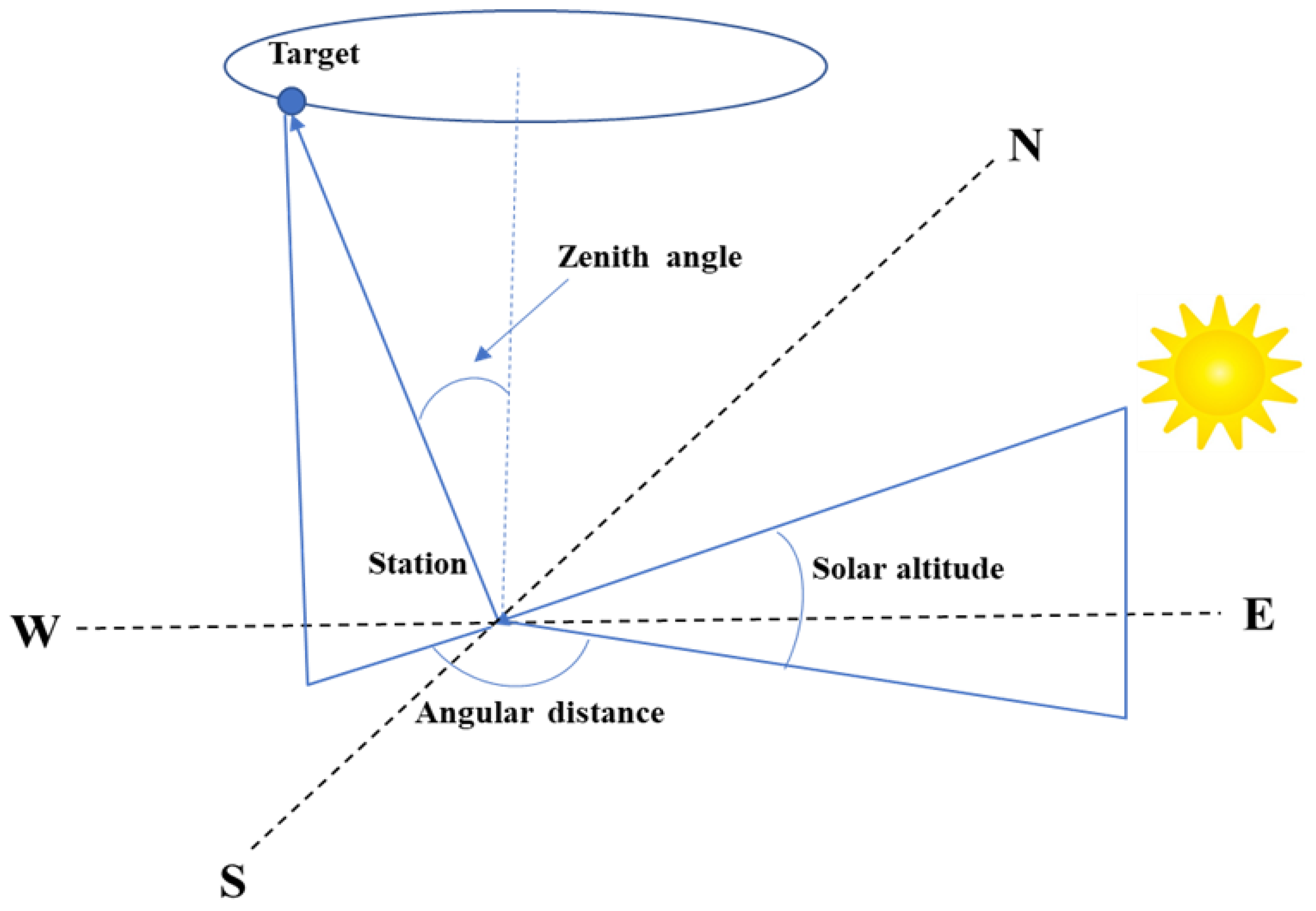
2. Establishment of the Maximum Detection Range Model

The echo photoelectron number is one of the most important parameters to evaluate the probability of a successful detection. The principle of DLR is the same as that of SLR, which measures the distance, according to the round-trip time, of the laser pulse between the station and the space target. However, the laser is fully reflected on the surface of the satellite and diffused on the surface of the space debris. Assume the effective reflection area of the space debris is equivalent to a circle with diameter D and diffused reflection occurs in the 2π solid angle opposite to the laser incident direction; then, the average photoelectron number n 0 of diffused laser ranging echo is [15]:
n 0 = λ η q hc 2 E t A r A s ρ cos θ π 2 θ t 2 R 4 T 2 η t η r α ,
where n 0 is the average number of echo photoelectrons of the single-pulse laser received by the system; λ is the wavelength of the laser; η q is the quantum efficiency of the detector; h is Planck’s constant; c is the speed of light in a vacuum; E t is the energy of a single pulse of the laser; A r is the effective receiving area of the telescope; A s is the effective reflecting area of the space debris (replaced by RCS); ρ is the reflectivity of the target; θ is the angle of the laser and the normal to the surface of the debris (assuming that the laser is at positive incidence; then, θ = 0 degree and cos θ = 1 ); θ t is the divergence angle of the laser beam; R is the orbit distance of the space debris; T is the one-way atmospheric transmission; η t is the transmission efficiency of the emitting system; η r is the transmission efficiency of the receiver system; and α is the atmospheric attenuation factor.
Photoelectrons generated by photoelectric conversion on the surface of the detector obey the Poisson distribution. According to the Poisson distribution, the average number of signal photoelectrons is n 0 , and the probability of producing m photoelectrons is denoted as:
P ( m , n 0 ) = exp ( n 0 ) m ! n 0 m .
Then, the probability of producing one or more signal photoelectrons is:
P D = 1 exp ( n 0 ) .
In the DLR system, the sky background noise during daytime is 106 times larger than that at night [10], which is a key factor affecting the success probability of the ranging system. The echo signal received by the detector contains not only signal echoes, but also targets blackbody radiation noise, backscattering noise, detector dark noise, and daytime sky background noise. For the daytime DLR process, the noise mainly comes from the sky background noise, and other noises can be ignored. Therefore, the daytime sky background noise was mainly considered in the estimation of noise intensity in this paper. The estimation formula is as follows [16]:
N B = π 4 N λ θ r 2 A r q η r η q .
where N B is the average photoelectron number rate generated by background noise on the photosensitive surface of the detector. N λ is the SKR; θ r is the receiving field of the view angle; and q is the ratio of the transmission band of the interference filter to the response band of the receiving device.
Range gate is a method of time filtering. A successful detection occurs only in the situation that the single-photon avalanche diode (SPAD) is enabled when the echo signal just comes back. Assume the range gate is set to L ; the number of noise photoelectrons generated during the validity period of the range gate is expressed as:
N = N B × L .
The photoelectrons generated by the photoelectric conversion of noise photons on the photosensitive surface of the detector also obey the Poisson distribution; then, according to the Poisson distribution, the false alarm rate of the detector is expressed as:
P FA = P ( 1 , N ) = 1 exp ( N ) .
In the DLR process, the detector can detect the signal up to the single-photon level. Set the detection threshold of the detector as a single photon; then, the detection success probability threshold can be expressed as [17]:
P min = ( 1 P FA ) P Dmin .
where P min is the minimum signal detection success probability of the system; and P Dmin is the minimum probability that the signal successfully triggers the detector. The successful detection of the signals by the system requires that the detector is triggered by signals and not triggered by noise. For system detection, the minimum detection threshold occurs when the noise does not trigger the detector, that is, assuming “no” noise, N = 0 , and at the same time, the detection threshold is a single photon; then, the formula is simplified as:
P min = ( 1 P FA ) P Dmin = 1 exp ( η q ) .
The MDR value of the system is one of the important indicators to evaluate the detection capability of the system. From Formulas (1)–(8) above, the MDR value of the 1064 nm DLR system to detect space debris targets can be expressed as:
R max = { 2 λ η q E t A r A s ρ cos ( θ ) T 2 η t η r α ln { 1 [ 1 exp ( η q ) ] exp ( π 4 N λ θ r 2 A r q η r η q L ) } hc π 2 θ r 2 } 4 .
The basic parameters of the 1064 nm DLR system and debris target information are shown in Table 1.
According to the parameter values in Table 1, Formula (9) can be simplified as:
R max = 2.69 × 10 20 × A s × T 2 - l n [ 1 - 0.18 × e x p ( 1.82 × 10 - 18 × N λ ) ] 4 .
It can be seen that, for space debris targets with different reflection cross-section areas, when the system parameters are selected, the MDR value of the system is mainly affected by SBR and atmospheric transmission, and the effects of SBR and atmospheric transmission should be comprehensively considered in the evaluation of the system performance.
In this paper, the influence factors of SBR and atmospheric transmission in MDR model were studied using the MODTRAN software (PcModWin 3.7). MODTRAN, developed from the LOWTRAN code, is an atmospheric simulation software that was developed by the US Air Force Geophysical Laboratory (AFGL) more than 30 years ago, which can calculate the atmospheric transmission and radiance over a specified path. The minimum spectral resolution calculated by MODTRAN can reach 2 cm−1. Its applicable wave number ranges from 0 to 50,000 cm−1. The software has a high computational efficiency and is recognized as one of the most widely used radiative transmission computing software around the world [18,19].

3. Analysis of the Influencing Factors

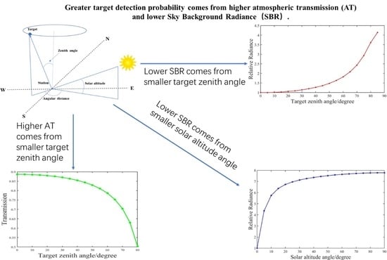
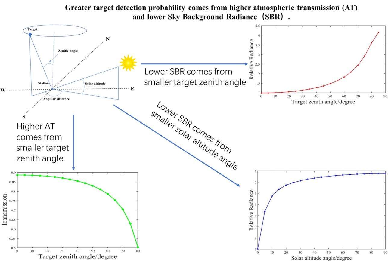
3.1. Analysis of the Influencing Factors of Atmospheric Transmission
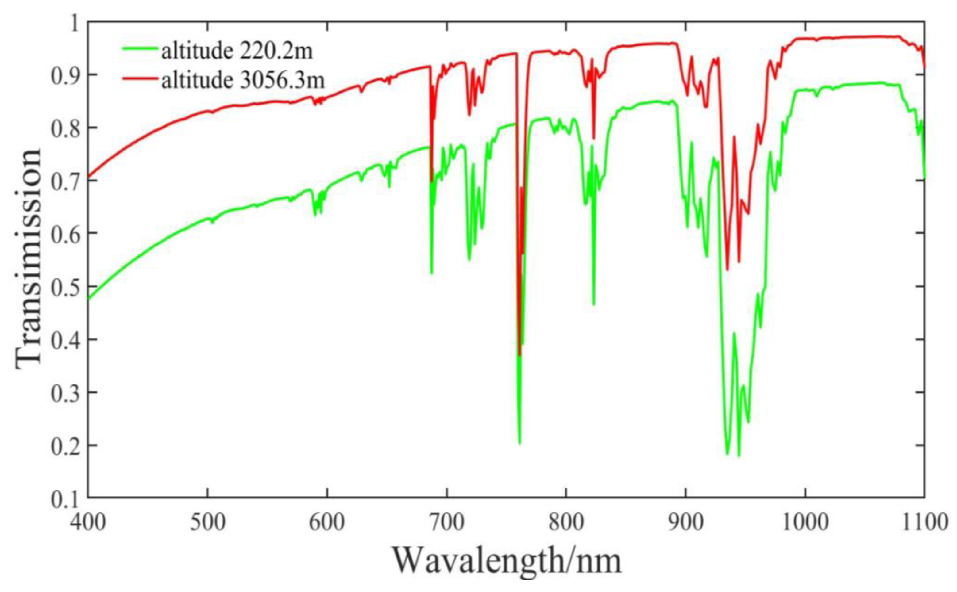
3.1.1. Altitude

The Earth’s atmosphere is made up of various gases and aerosol particles suspended in them. In the DLR process, when the laser is transmitted through the atmosphere, it will interact with the components of the atmosphere, including absorption, scattering, refraction, and reflection. The atmospheric absorption and scattering significantly weaken the laser energy. This effect reduces the atmospheric transmission of the laser. Aerosols and water vapor in the atmosphere selectively absorb light of different wavelengths. In clear weather, the atmospheric transmission is also affected by the altitude of the station and the zenith angle of the target. In the calculation of atmospheric transmission, it is assumed that the atmosphere consists of infinitely concentric spheres of uniform concentration at vertical height. In order to compare the atmospheric transmission at different altitudes, the Haleakala station with the highest altitude in the ILRS joint ranging station and the temporary outfield test site of the Changchun Station were selected, with altitudes of 3056.3 m and 220.2 m, respectively. The atmospheric transmission of the two sites was calculated when the target zenith angle was 0°. In the simulation process, based on the principle of a single variable, when studying a certain influencing factor, other influencing factors remain unchanged. The calculated results are shown in Figure 1.
As it can be seen in Figure 1, the atmospheric transmission of 1064 nm wavelength light is higher than that of 532 nm, which is also one of the reasons why the DLR system prefers a 1064 nm wavelength laser. It can also be seen that the atmospheric transmission increases with the altitude for the same wavelength light.

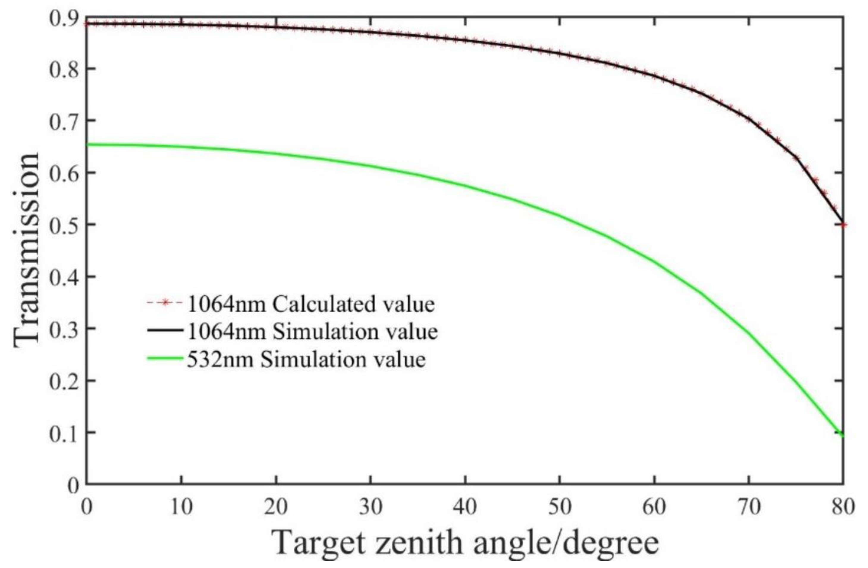
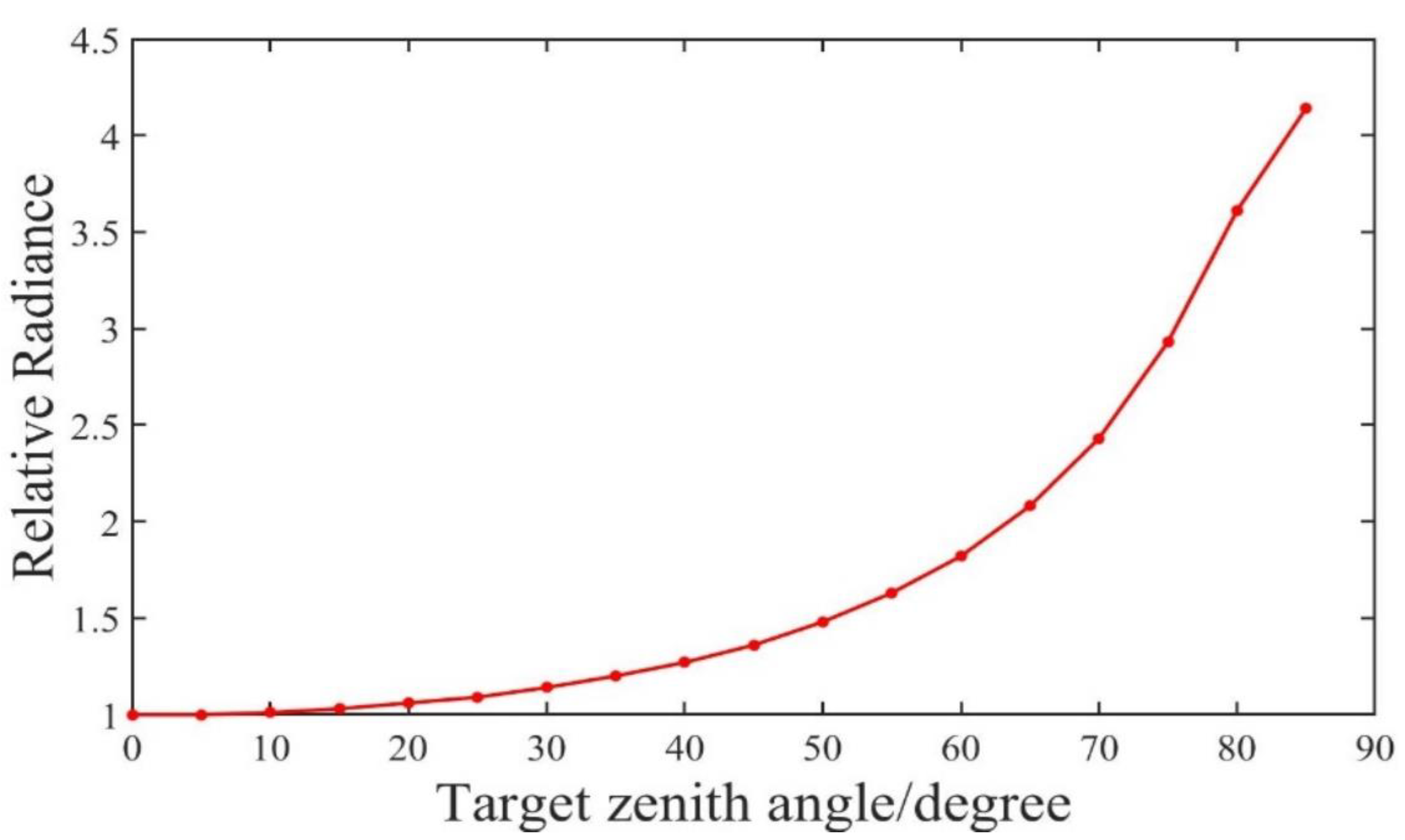
3.1.2. Target Zenith Angle

When the altitude is fixed, the atmospheric transmission is mainly related to the zenith angle of the target. The atmospheric transmission T at any zenith angle ψ can be expressed as [20]:
T = T 0 sec ( ψ ) .
where T 0 is the atmospheric transmission when the target zenith angle is 0°, whose typical value is 0.89; and ψ expressed in degrees.
The variation in the atmospheric transmission with the target zenith angle was calculated and compared to the MODTRAN simulation values. The results are shown in Figure 2.
It can be seen in Figure 2 that the calculated values of the atmospheric transmission and the simulated curves basically coincide, which verifies well the effectiveness of the model formula and the MODTRAN software. The atmospheric transmission of 1064 nm light is generally higher than that of 532 nm light, especially at a low elevation angle (corresponding to a high zenith angle). Therefore, from the perspective of atmospheric transmission, a higher elevation angle facilitates observation.

3.2. Analysis of the Influencing Factors of SKR
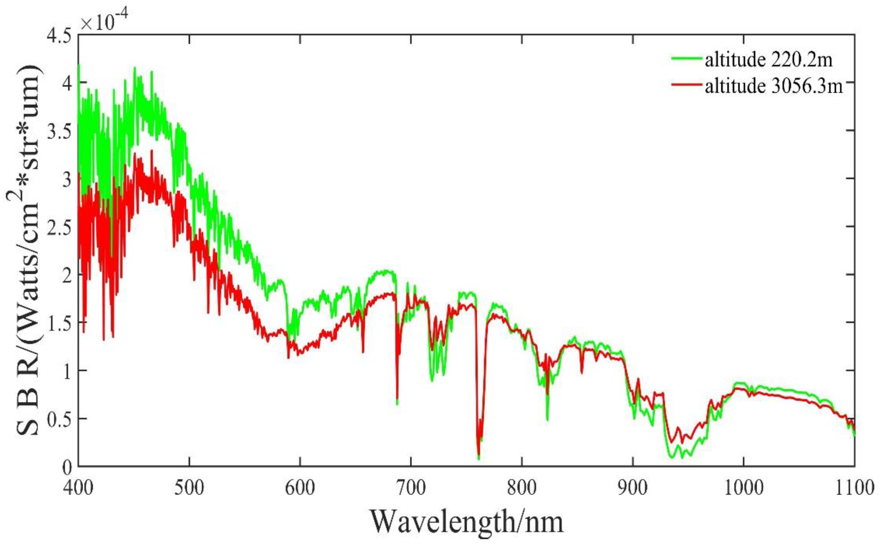
3.2.1. Altitude

Daytime sky background noise is mainly related to SBR, which is mainly affected by the altitude of the observation point, the altitude angle of the sun, the zenith angle of the target, and the angular distance, as shown in Figure 3.
When designing the DLR system, in order to prevent the telescope from facing the sun directly, a 30° avoidance zone was set in the observation azimuth and elevation. In the simulation process, we also set a 30° avoidance zone.
The changes in SBR with the wavelength at the two altitude sites were calculated. The results are shown in Figure 4.
As it can be seen in Figure 4, the SBR of the 1064 nm wavelength light is one order of magnitude lower than that of 532 nm wavelength light; the SBR of 1064 nm wavelength is basically equal at the two sites; so, the altitude has little effect on the SBR in the near-infrared wavelength compared to that of 532 nm wavelength light.

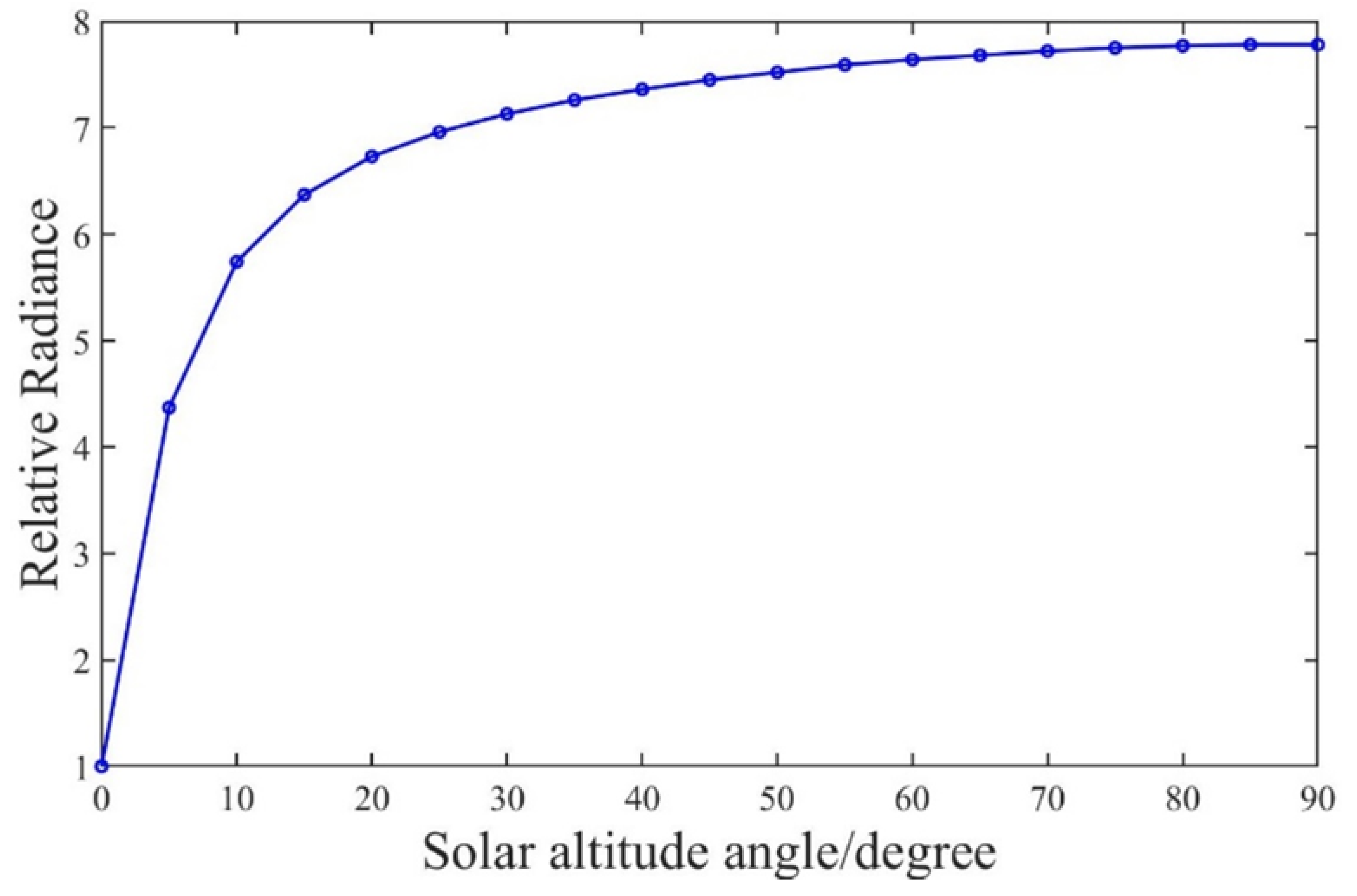
3.2.2. Solar Altitude Angle

When the solar altitude angle increased from 0° to 90°, the SBR of 1064 nm wavelength light varying with the angle was calculated, and the result is shown in Figure 5.
As it can be seen in Figure 5, the SBR at 1064 nm wavelength increases rapidly with the increase in the solar altitude angle, and when the solar altitude angle reaches 50°, the SBR tends to flatten out.
In order to represent the relationship between SBR and the solar altitude angle ϕ , a fourth-order polynomial was fitted, which is expressed as:
N λ S ( ϕ ) = N λ S ( 0 ) ( 10 6 ϕ 4 + 2 × 10 4 ϕ 3 0 . 0164 ϕ 2 + 0 . 5182 ϕ + 1 . 558 2 ) .
where N λ S ( 0 ) is the SBR of 1064 nm wavelength light when the solar altitude angle is 0° (the target zenith angle is also 0°), and the typical value is 7.37 × 10⁻⁵ W/(cm2·str·µm). The altitude angle of the sun ϕ is expressed in degrees.

3.2.3. Target Zenith Angle

When the target zenith angle increased from 0° to 85°, the SBR of 1064 nm wavelength light varying with the angle was calculated, and the result is shown in Figure 6.
As it can be seen in Figure 6, the SBR of 1064 nm wavelength light increases with the increase in the target zenith angle, that is, the higher the target elevation angle, the smaller the SBR. In order to represent the relationship between SBR and target zenith angle, a fourth-order polynomial was fitted, which is expressed as:
N λ Z ( ψ ) = N λ Z ( 0 ) ( 3 × 1 0 - 7 ψ 4 3 × 10 - 5 ψ 3 + 0 . 001 ψ 2 0 . 0073 ψ + 1 . 002 5 ) .
where N λ Z ( 0 ) is the SBR of 1064 nm wavelength light when the target zenith angle is 0° (the solar altitude angle is also 0°), and the typical value is 7.37 × 10⁻⁵ W/(cm2·str·µm). The target zenith angle ψ is expressed in degrees.

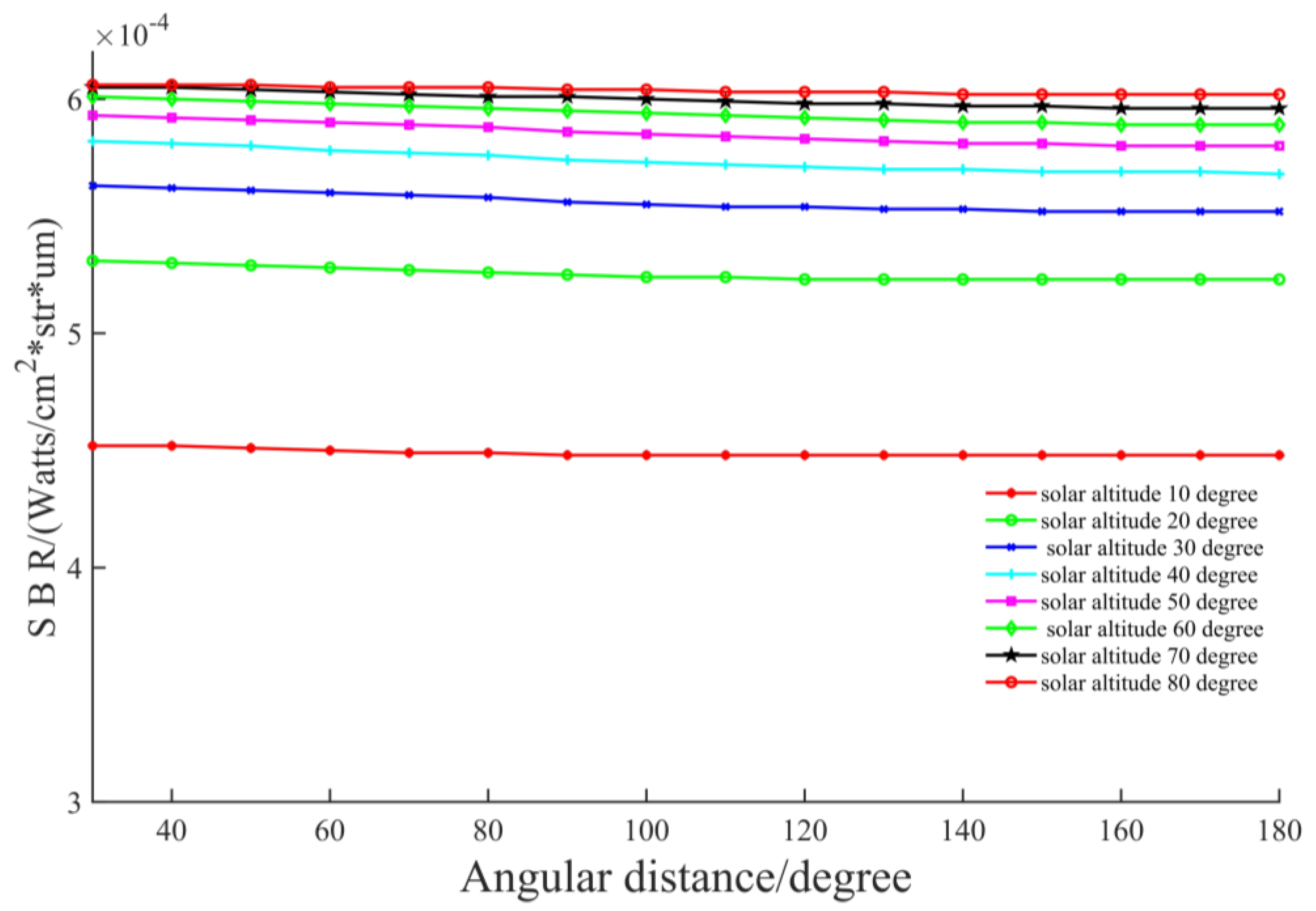
3.2.4. Angular Distance

When the solar altitude angle increased from 10° to 80°, the SBR of 1064 nm wavelength light changing with the angular distance was calculated, and the result is shown in Figure 7.
As it can be seen in Figure 7, the SBR of 1064 nm wavelength light has a flat shape with each solar altitude angle and basically, does not change with the angular distance.
When evaluating the performance of the system, the atmospheric transmission mainly affects the number of echo signal photons of the system. If other conditions remain unchanged, the higher the atmospheric transmission, the more echo photons there are, and the greater the probability of the signal being detected. SBR mainly affects the noise level of the system. The larger the SBR, the larger the noise, the higher the false alarm rate of the system, and the lower the success probability of the signal detection.
Based on the above theoretical analysis and simulation experiments, it can be concluded that the atmospheric transmission at 1064 nm wavelength is generally higher than that at 532 nm, especially at low elevation angles. The SBR of 1064 nm wavelength light is generally lower than that of 532 nm. So, a condition that is needed for improving the detection capability of the system is a high atmospheric transmission, which comes from a high altitude and low target zenith angle; another condition that is needed is a low SBR, which comes from the small target zenith angle and a low solar altitude; but the angular distance basically does not affect the detection performance of the system.
By integrating Formulas (11)–(13) into Formula (10), it can be obtained that the MDR formula of the system is:
R max = { 2 . 69 × 10 20 × A s × T 0 2 sec ( ψ ) ln [ 1 0 . 18 × exp ( 1 . 82 × 10 18 × N λ S ( ϕ ) × N λ Z ( ψ ) ÷ N λ ( 0 ) ) ] } 4 N λ S ( ϕ ) = N λ S ( 0 ) ( 10 6 ϕ 4 + 2 × 10 4 ϕ 3 0 . 0164 ϕ 2 + 0 . 5182 ϕ + 1 . 558 2 ) N λ Z ( ψ ) = N λ Z ( 0 ) ( 3 × 1 0 7 ψ 4 3 × 10 5 ψ 3 + 0 . 001 ψ 2 0 . 0073 ψ + 1 . 002 5 ) N λ S ( 0 ) = N λ Z ( 0 ) = N λ ( 0 )

4. Experiment and Model Verification
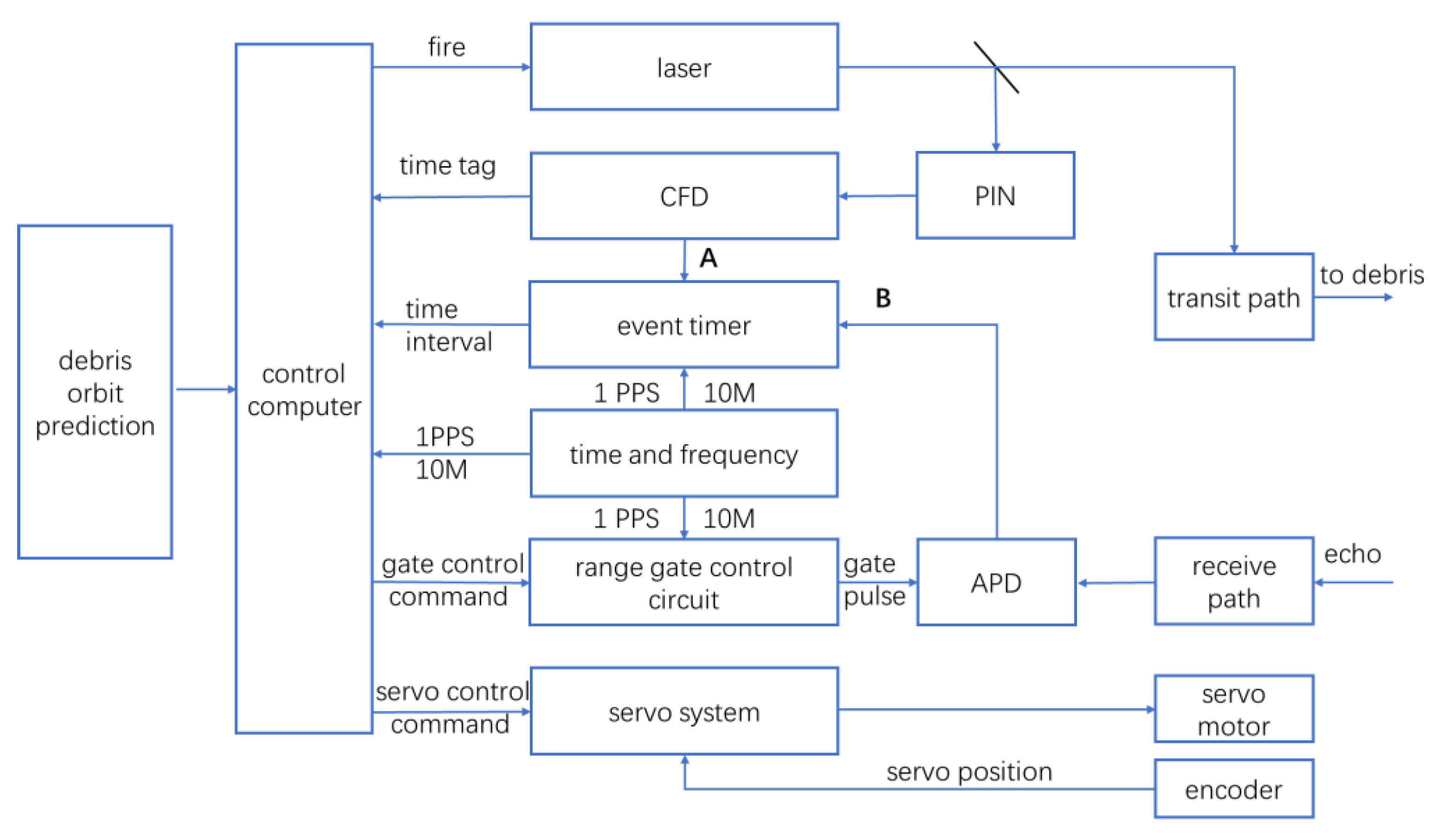
4.1. Experiment

In order to verify the validity of the MDR model, a temporary experimental platform was set up at the outfield test site of Changchun Station. Debris targets with an orbit distance of 700~1100 km and a cross-section area of 4~10 m2 were selected as the observed target. On clear days, the DLR experiment of the 1064 nm wavelength laser was carried out on 27 March, 28 March, and 1 April 2023. The detailed observation process was as follows: First, the TLE prediction of the space debris target was downloaded; then, coordinate conversion, the pass period, azimuth angle, elevation angle, and orbit distance of the space debris relative to the location of the ranging station were obtained. When the target passed through, the servo system guided the telescope to track the target, and when the tracking was stable, the laser was controlled to emit the laser. The laser was transmitted in two ways: one way through the main wave detector (PIN) to complete the photoelectric conversion to generate an electrical signal, and by the correction of the constant ratio timing discriminator (CFD), it was sent to channel A of the event timer (ET) to record the laser emission time. When the other path reached the target and was reflected, it was received by the receiving telescope, and the photoelectric conversion was completed on the SPAD to generate the electrical signal, which was sent to channel B of ET to record the receiving time of the echo. The initial value of the distance between the target and the ranging telescope can be obtained by calculating the difference of the time of the A–B channel. Figure 8 shows the system structure diagram.

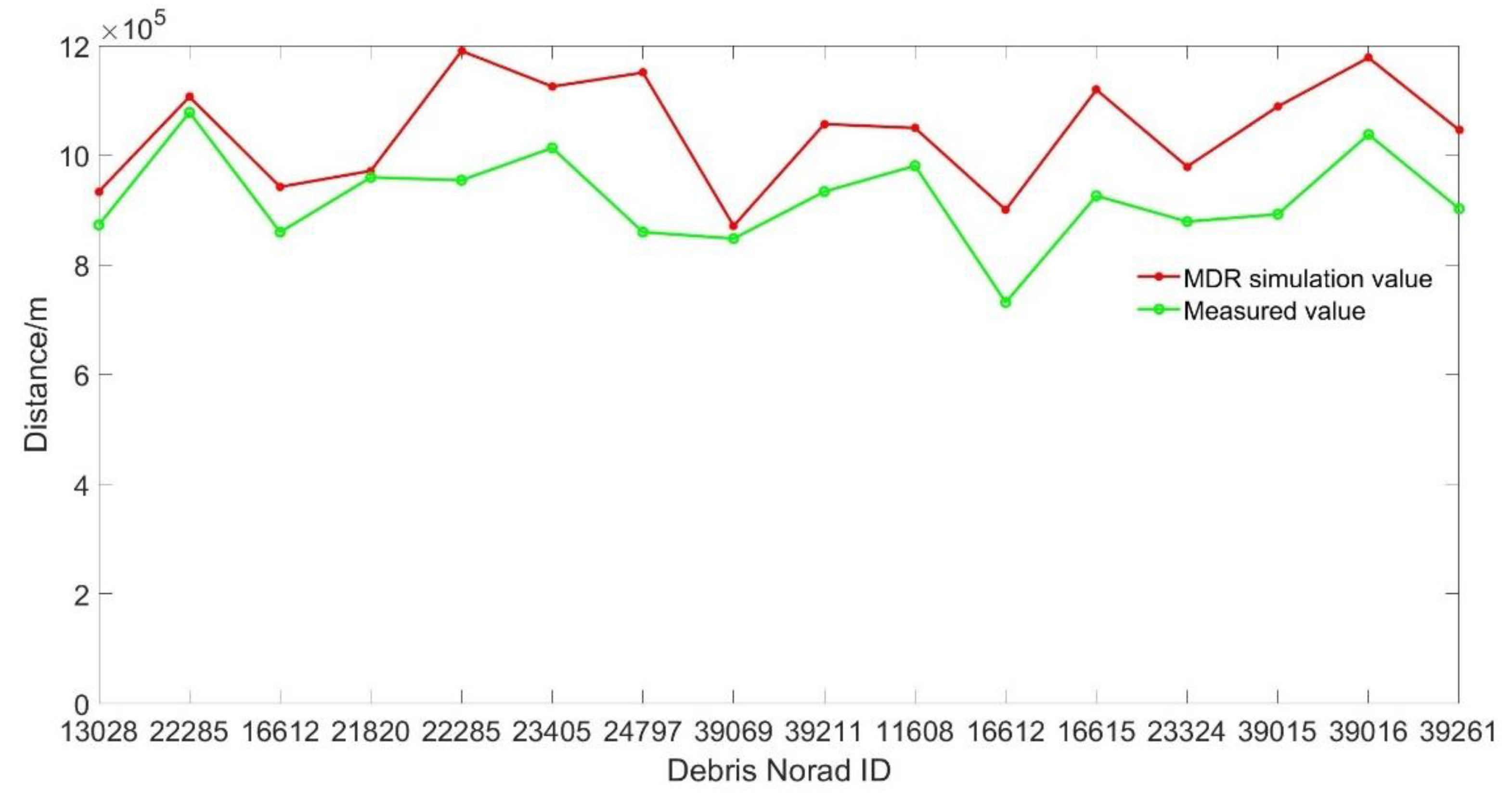
4.2. Model Verification

According to the orbit prediction of space debris, information such as the angle coordinates of the sun and debris at the observation time can be obtained. According to the theoretical analysis in Section 2, the atmospheric transmission and SBR values at the observation time can be estimated through the angle information about the sun and debris, combined with the parameters of the 1064 nm DLR system and the RCS values of debris. The MDR model in Formula (14) can be used to calculate the simulation value of MDR, and the results of the simulation value and the measured value are shown in Table 2. The MDR simulation values and the measured values of the different debris are shown in Figure 9.
Through the data analysis in Table 2, it is obtained that the MDR model of the 1064 nm DLR system reached 86% agreement, which basically proves the reliability of the model. However, relative error values of 24.51% and 34.33% still occur, and at the same time, the simulation values and the measured distance of debris are different to some extent. Possible reasons for this are as follows:
(1)
In the estimation process, it was assumed that the laser was normally incident on the space debris, while in the actual measurement, the normal incident laser cannot be guaranteed;
(2)
In the estimation process, the average or typical values of laser reflectivity and other parameters of the debris were used, but the parameter values of the different debris targets were different;
(3)
The shape of space debris was different. Space debris was mostly diffused reflectors with irregular shapes, and the flatness of the reflecting surfaces was also very different;
(4)
The space debris was in a spin state in the space, which increased the uncertainty of the relative position of the laser and the reflector in the actual measurement.

5. Conclusions

Based on the radar equation and system noise characteristics, the MDR model of the 1064 nm DLR system is established by considering SBR and atmospheric transmission. Through theoretical analysis and simulation experiments, the influencing factors of the atmospheric transmission and SBR are studied, and the influencing factors are normalized into the MDR model by polynomial fitting. The results indicate that a high atmospheric transmission comes from a high altitude and low target zenith angle; a low sky background radiance comes from the small target zenith angle and a low solar altitude angle, while the angular distance has no obvious influence on the sky background radiance. On a clear day, the DLR experiments of 1064 nm wavelength were carried out on debris targets at a distance of 700~1100 km and RCS of 4~10 m2, which verified the accuracy of the MDR model of the system. We analyzed the possible causes for the differences from the perspective of model calculation, target shape characteristics, and attitude characteristics. The research provides a reference value for the performance evaluation and subsequent upgrading of the 1064 nm wavelength space debris laser ranging system.

Author Contributions

Conceptualization, C.F., G.W. and M.Z.; methodology, C.F., G.W. and M.Z.; software, C.F., G.W. and M.Z.; validation, C.F., G.W. and M.Z.; formal analysis, C.F., G.W. and M.Z.; investigation, Q.S., B.G. and S.W.; resources, C.L. and C.F.; data curation, C.L. and C.F.; writing—original draft preparation, M.Z.; writing—review and editing, M.Z.; visualization, M.Z.; supervision, C.F. and G.W. All authors have read and agreed to the published version of the manuscript.

Funding

This research was funded by the Jilin Province Science and Technology innovation and the entrepreneurship outstanding talents (team) project, China, grant number 20220508147RC.

Data Availability Statement

The data presented in this study are available upon request from the corresponding author. The data are not publicly available due to privacy.

Conflicts of Interest

The authors declare no conflicts of interest.

References

  1. Wei, D.; Zhao, C.Y. Analysis on the accuracy of the SGP4/SDP4 model. Acta Astron. Sin. 2009, 50, 332–339. [Google Scholar]
  2. Zhang, Z.P.; Cheng, Z.E.; Zhang, H.F.; Deng, H.R.; Jiang, H. Observation of space debris by ground-based laser ranging system and research on detecting ability. Infrared Laser Eng. 2017, 46, 15–21. [Google Scholar]
  3. Meng, W.D.; Zhang, H.F.; Deng, H.R.; Tang, K.; Wu, Z.B.; Wang, Y.R.; Wu, G.; Zhang, Z.P.; Chen, X.Y. 1.06 μm wavelength based high accuracy satellite laser ranging and space debris detection. Acta Phys. Sin. 2020, 69, 1. [Google Scholar] [CrossRef]
  4. Wang, N.; Deng, H.R.; Zhang, H.F.; Wu, Z.B.; Zhang, Z.P. Daytime background noise analysis and application research in1064 nm band. Laser Infrared 2019, 49, 1190–1194. [Google Scholar]
  5. Craig, H.S.; Greene, B. The EOS space debris tracking system. In Proceedings of the Advanced Maui Optical and Space Surveillance Technologies Conference, Wailea, Maui, HI, USA, 10–14 September 2006. [Google Scholar]
  6. Kirchner, G.; Koidl, F.; Kucharski, D.; Ploner, M.; Riede, W.; Voelker, U.; Buske, I.; Friederich, F.; Baur, O.; Krauss, S.; et al. Space debris laser ranging at Graz. In Proceedings of the 6th European Conference on Space Debris, Darmstadt, Germany, 22–25 April 2013; Volume 723, p. 9. [Google Scholar]
  7. Tang, R.F.; Zhai, D.S.; Zhang, H.T.; Pi, X.Y.; Li, C.X.; Fu, H.L.; Li, R.W.; Li, Z.L.; Li, Y.Q. Research Progress in space debris laser ranging. Space Debris Res. 2020, 20, 21–30. [Google Scholar]
  8. Lejba, P.; Suchodolski, T.; Michałek, P.; Bartoszak, J.; Schillak, S.; Zapaśnik, S. First laser measurements to space debris in Poland. Adv. Space Res. 2018, 61, 2609–2616. [Google Scholar] [CrossRef]
  9. Sproll, F.; Hampf, D.; Wagner, P.; Riede, W.; Eckl, J.; Riepl, S.; Schreiber, U.; Bamann, C.; Hugentobler, U.; Kirchner, G.; et al. Two-color and multistatic space debris laser tracking. In Proceedings of the 20th International Workshop on Laser Ranging, Potsdam, Germany, 9–14 October 2016. [Google Scholar]
  10. Li, Z.L.; Zhai, D.S.; Zhang, H.T.; Pi, X.Y.; Fu, H.L.; Li, R.W.; Li, P.F.; Zhang, L.B.; Li, Y.Q. Superconductivity detector applied to daytime satellite laser ranging experiment and research. Infrared Laser Eng. 2020, 49, 127–132. [Google Scholar]
  11. Dong, X.; Han, X.W.; Song, Q.L.; Liang, Z.P.; Fan, C.B.; Zhang, H.T. Research of space debris laser ranging system. Infrared Laser Eng. 2016, 45, 40–45. [Google Scholar]
  12. Liu, K.; Cui, Z.Z. Research on the maximum detection range in pulse laser detection. Opt. Tech. 2011, 37, 143–147. [Google Scholar]
  13. Gao, S.F.; He, M.L.; Wang, Z.; Zhang, M.; Wu, P.; Zhang, G.B. Estimation of the Detection Distance of Infrared Target. Infrared 2008, 29, 21–24. [Google Scholar]
  14. Zhang, J.H.; Yao, D.S.; Tan, B. Analysis on Effect Factors of Ground-Based Electro-Optic System Detection Ability on Space Object. Acta Opt. Sin. 2008, 28, 1178–1182. [Google Scholar] [CrossRef]
  15. Liu, J. Study on Diffuse Laser Ranging. Master’s Thesis, Yunnan Observatories, Chinese Academy of Sciences, Yunnan, China, 2007. [Google Scholar]
  16. Lv, B.T.; An, N.; Han, X.W.; Cheng, C.; Feng, X.H.; Zhang, Y.D.; Gao, J.; Song, Q.L.; Liu, C.Z. Research on SLR Echo Characteristics Based on Lidar Atmospheric Correction Model. Acta Opt. Sin. 2024, 44, 1201007. [Google Scholar]
  17. An, N.; Chen, Y.F.; Liu, C.Z.; Fan, C.B.; Liu, Y.; Song, Q.L.; Wen, G.Y. Maximum Detection Range of Satellite Laser Ranging System Based on Characteristics of Laser Transmission in Atmosphere. Acta Opt. Sin. 2018, 38, 23–28. [Google Scholar]
  18. Sun, F.Y. Study on the Characteristic of the Whole Sky Background Radiation. Master’s Thesis, University of Science and Technology of China, Hefei, China, 2016. [Google Scholar]
  19. Liu, Z.X. Research on Sky Background Spectral Radiance Measuring System for Self-Adapting Object Track. Master’s Thesis, University of Chinese Academy of Sciences, Beijing, China, 2012. [Google Scholar]
  20. Shell, J.R. Optimizing orbital debris monitoring with optical telescopes. In Proceedings of the Advanced Maui Optical and Space Surveillance Technologies Conference, Maui, HI, USA, 14–17 September 2010; p. E42. [Google Scholar]
Figure 1. Atmospheric transmission at different altitudes.
Remotesensing 16 00727 g001
Figure 2. The calculated and simulated values of the atmospheric transmission of 1064 nm wavelength light vary with the target zenith angle and the simulation of the atmospheric transmission of 532 nm wavelength light.
Remotesensing 16 00727 g002
Figure 3. Range schematic diagram of the DLR system.
Remotesensing 16 00727 g003
Figure 4. The SBR varies with the wavelength at different altitudes.
Remotesensing 16 00727 g004
Figure 5. The SBR varies with the solar altitude angle at a 1064 nm wavelength.
Remotesensing 16 00727 g005
Figure 6. The SBR varies with the target zenith angle at a 1064 nm wavelength.
Remotesensing 16 00727 g006
Figure 7. The SBR varies with the angular distance at a 1064 nm wavelength.
Remotesensing 16 00727 g007
Figure 8. Structure diagram of the DLR system.
Remotesensing 16 00727 g008
Figure 9. MDR simulation values and measured values of the 1064 nm DLR system.
Remotesensing 16 00727 g009
Table 1. Parameters of the 1064 nm DLR system and debris target information.
ParameterNameValue
Wavelength λ /nm1064
Quantum efficiency of SPADηq0.2
Single-pulse energy emitted by the laser E t /J0.4
Effective area of the receiving telescope A r /m21.079
The angle between the laser incident angle and the normal of the debris surface θ /(°)0
Atmospheric transmission T -
SBR of the 1064 nm laser N λ /(W/cm2·str·µm)-
Transmission efficiency of the emitting system η t 0.8
Transmission efficiency of the receiver system η r 0.6
Divergence angle of the emitting laser beam θ t /(″)10
Receiving field angle of view θ r /(″)8
Gate width L /µs7
The ratio of the transmission band of the interference filter to the response band of the receiving device q 1/667
Planck constant h /(J·s)6.63 × 10−34
Velocity of the laser c /(m/s)3 × 108
Effective reflection area of space debris A s /m2~=RCS
Reflection of space debris (rms) ρ 0.18
Atmospheric attenuation factor α /dB13
Table 2. Comparison of the MDR simulation values and the measured values of the 1064 nm DLR system.
DateNorad IDRCS/m2Orbit Perigee × Apogee/kmMDR Simulation Value/mMeasured Value/mError Rate
27 March 2023130284.398749 × 776937,224.0872,961.57.36%
27 March 2023222858.8221838 × 8461,111,983.91,078,370.93.12%
28 March 2023166124.337601 × 627942,529.6859,844.69.62%
28 March 2023218205.2429436 × 2976976,334.0959,765.21.73%
28 March 2023222858.8221838 × 8461,171,330.3954,567.622.71%
28 March 2023234058.6716838 × 8441,124,239.51,013,501.210.93%
28 March 20232479710.1469582 × 9011,155,082.4859,912.134.33%
28 March 2023390693.3329243 × 479874,450.4847,999.93.12%
28 March 2023392117.9642454 × 6061,067,440.2933,777.714.31%
1 April 2023116086.5623832 × 9131,048,571.5980,871.26.90%
1 April 2023166124.337601 × 627911,069.1731,724.924.51%
1 April 2023166157.0057776 × 7921,102,689.8926,141.119.06%
1 April 2023233246.2884793 × 877992,900.5879,063.712.95%
1 April 2023390156.4763828 × 13581,075,056.9892,550.420.45%
1 April 20233901610.051826 × 13581,173,642.41,038,042.913.06%
1 April 2023392618.0334757 × 8031,059,309.8902,523.517.37%
Note: Error   rate = | MDR   simulation   value - Measured   value Measured   value × 100 100 | .
Disclaimer/Publisher’s Note: The statements, opinions and data contained in all publications are solely those of the individual author(s) and contributor(s) and not of MDPI and/or the editor(s). MDPI and/or the editor(s) disclaim responsibility for any injury to people or property resulting from any ideas, methods, instructions or products referred to in the content.

