Technical Note

Enhancing SAR Multipath Ghost Image Suppression for Complex Structures through Multi-Aspect Observation

Radar Monitoring Technology Laboratory, School of Information Science and Technology, North China University of Technology, Beijing 100144, China
*
Author to whom correspondence should be addressed.
Remote Sens. 2024, 16(4), 637; https://doi.org/10.3390/rs16040637
Submission received: 29 December 2023 / Revised: 3 February 2024 / Accepted: 7 February 2024 / Published: 8 February 2024
(This article belongs to the Special Issue Advances in Synthetic Aperture Radar Data Processing and Application)

Abstract

:
When Synthetic Aperture Radar (SAR) observes complex structural targets such as oil tanks, it is easily interfered with by multipath signals, resulting in a large number of multipath ghost images in the SAR image, which seriously affect the image clarity. To address this problem, this paper proposes a multi-aspect multipath suppression method. This method observes complex structural targets from different azimuth angles to obtain a multi-aspect image sequence and then uses the difference in sequence features between the target image and the multipath ghost image with respect to aspect angle to separate them. This paper takes a floating-roof oil tank as an example to analyze the propagation path and the ghost image characteristics of multipath signals under different observation aspects. We conclude that the scattering center of the multipath ghost image changes with the radar observation aspect, whereas the scattering center of the target image does not. This paper uses the Robust Principal Component Analysis (RPCA) method to decompose the image sequence matrix into two parts: a sparse matrix and a low-rank matrix. The low-rank matrix represents the aspect-stable principal component in the image sequence; that is, the real scattering center. The sparse matrix represents the part of the image sequence that deviates from the principal component; that is, the signal that varies with aspect, mainly including multipath signals, sidelobes, anisotropic signals, etc. By reconstructing the low-rank matrix and the sparse matrix, respectively, we can obtain the image after multipath signal suppression and also the multipath ghost image. Both the target and the multipath signal provide useful information. The image after multipath signal suppression is useful for obtaining the structural information of the target, and the multipath ghost image is useful for analyzing the multipath phenomenon of the complex structure target. This paper conducts experimental verification using real airborne SAR data of an external floating roof oil tank and compares three methods: RPCA, PCA, and sub-aperture fusion method. The experiment shows that the RPCA method can better separate the target image and the multipath ghost image.

1. Introduction

Due to its all-day, all-weather, long-range, high-resolution imaging capabilities [1,2], SAR has been an important tool in applications like resource mapping [3], environmental monitoring [4], and disaster assessment [5]. Oil tanks are crucial monitoring targets in SAR remote sensing applications. Oil tank monitoring aids in getting information on oil storage levels, identifying potential safety risks, and averting leaking accidents.
SAR uses microwave signals to generate images that enable it to penetrate clouds and darkness. This is particularly beneficial for continuous monitoring because it can operate seamlessly under various environmental conditions. This technology can identify structural details, identify changes over time, and track potential problems or changes in oil tank configurations. Moreover, SAR’s ability to acquire multi-temporal data allows the creation of time-series imagery, enabling the detection of changes, movements, or anomalies associated with oil tanks. By analyzing these temporal patterns, SAR contributes to identifying potential risks, leakages, or structural modifications in oil storage facilities [6]. In essence, SAR emerges as a powerful tool not only for visualizing oil tanks but also for dynamic monitoring over time.
The structure of the oil tank is very complex. The electromagnetic wave signal will be reflected several times between the target’s inner wall and the floating roof during SAR observation [7,8], causing a large number of multipath ghost images. This will have a negative impact on the SAR image’s clarity, which will in turn affect the target’s identification and analysis.
Zhang [9,10,11], Horst [12], Carlos [13], Xu [14], and others analyzed the multipath scattering mechanism of oil tanks. The scattering characteristics of oil tanks in SAR images were analyzed in [9], which also set up a scattering model of oil tanks. In [10], a prediction model based on the multipath scattering properties in the oil tank SAR images is proposed by combining the principle of SAR and multipath scattering theory. The model can provide the relationship between the geometry parameters of the tank, the SAR parameters, the approximated position, and the scatting strength of the bright region in the SAR image. Ref. [11] proposed an approach to simulate SAR images of oil tanks by using the Shooting and Bouncing Rays (SBR) technique. The approach uses a ray perspective to calculate the scattering mechanism and deduces the approximate focus positions of the multipath rays according to the imaging formation process. Ref. [12] uses the Coherent Raytracing SAR simulator (CohRaS) to simulate both the amplitude and phase of the returned signal. The scattering returns from different objects in the scene are calculated using both geometrical and physical optics. Also, the multipath scattering characteristics of oil tanks and the causes of multipath scattering are analyzed in detail. Studies of oil tank SAR images and analyses of the scattering characteristics of oil tanks were also conducted in [13,14]. The multiple reflections produced by the oil tank’s outside wall are also taken into account in [14]. The above-mentioned articles, however, only analyze the SAR multipath scattering mechanism of oil tanks. They make no suggestions for suppressing multipath ghost images, which makes it impossible to solve the problem that multipath signals interfere with SAR images.
At present, domestic and foreign research on multipath ghost image suppression is mainly aimed at through-wall radar application scenes. In indoor contexts, the goal is to suppress multipath ghost images between targets and walls. The main multipath suppression methods include model-based multipath suppression methods and aspect-dependent sub-aperture methods.
By analyzing the interaction of electromagnetic waves between the target and the wall, P. Setlur et al. proposed a multipath suppression method based on the indoor electromagnetic wave propagation model [15]. Based on this model, the position of multipath ghost images can be calculated. Using a two-dimensional weighting function, this method implements the correlation mapping of the multipath ghost image. The two-dimensional weighting function exhibits a high peak at the real target point, but its amplitude value is near to zero at the ghost image position. Then the two-dimensional weighting function is multiplied with the original image to produce a synthetic image. The pixel intensity at the real target point can be improved and the multipath ghost image suppressed using the synthetic image. However, this method’s weighting function variance is chosen by experience, and the correlation effect is more affected by its value. P. Setlur proposed a multipath signal suppression method based on Point Spread Functions (PSFs) in [16]. This method eliminates the influence of arbitrary variance parameters on the two-dimensional weighting function, which is instead determined by the threshold associated with the system parameters. This type of multipath suppression method [17,18] ignores the multipath effect between different targets and requires prior knowledge of the observing background. Using the above methods to locate the position of the multipath ghost image is challenging for complex structural targets, such as oil tanks, especially when no prior knowledge is available.
After analyzing the multipath scattering model, Wang [19], Tan [20,21], and Li [22] discovered an important feature of the multipath ghost image to be defined as Aspect Dependence (AD). The feature shows that the position of the ghost image changes with the radar location. This feature can be used to identify and suppress multipath signals without requiring information on the observation background in advance. The author of [19] generated a series of sub-aperture images using Doppler frequency domain sub-aperture filtering, and then the changes in pixel intensity of these images were evaluated by normalized standard deviation. The multipath ghost image’s intensity sequence fluctuates because of aspect dependence. When the normalized standard deviation exceeds the predetermined threshold, it is regarded as a multipath ghost image to be suppressed. A multipath suppression method based on hidden Markov models (HMMs) was proposed in [20,21]. This method takes real targets in sub-aperture images as training samples to build an HMM model of the real targets and then uses the trained model to calculate the matching probability of all unclassified pixels. It is identified as a multipath false target if the matching probability is less than the threshold. A sub-aperture fusion method was proposed in [22]. It multiplies both the sub-aperture image and the original full-aperture picture in order to suppress the multipath ghost image that varies with the aperture and enhances the real target image. On this basis, Ref. [23] proposed a sub-aperture double-layer fusion method. This method divides the data into sub-apertures of different scales. The sub-aperture and full-aperture images are multiplied to create the first-layer image sequence. This first-layer image sequence is then grouped and multiplied to create the second-layer image, which can better suppress multipath ghost images. Ref. [24] presented a multipath suppression method based on group sparse. The real target has the same support set in different sub-aperture images. Based on this principle, the compressed sensing reconstruction algorithm obtains the real target image and suppresses the multipath ghost image. All of the above sub-aperture methods suppress multipath ghost images by using the feature of multipath ghost images that change with aperture. However, the suppression effect is limited and the difference in aperture is quite small. They are not suitable for complex structural targets like oil tanks and are mainly used in simple situations. The multipath ghost image of the oil tank has a large area, and some parts of them overlap with the oil tank image. Thus, the real target image and the multipath ghost image are difficult to distinguish using the above methods.
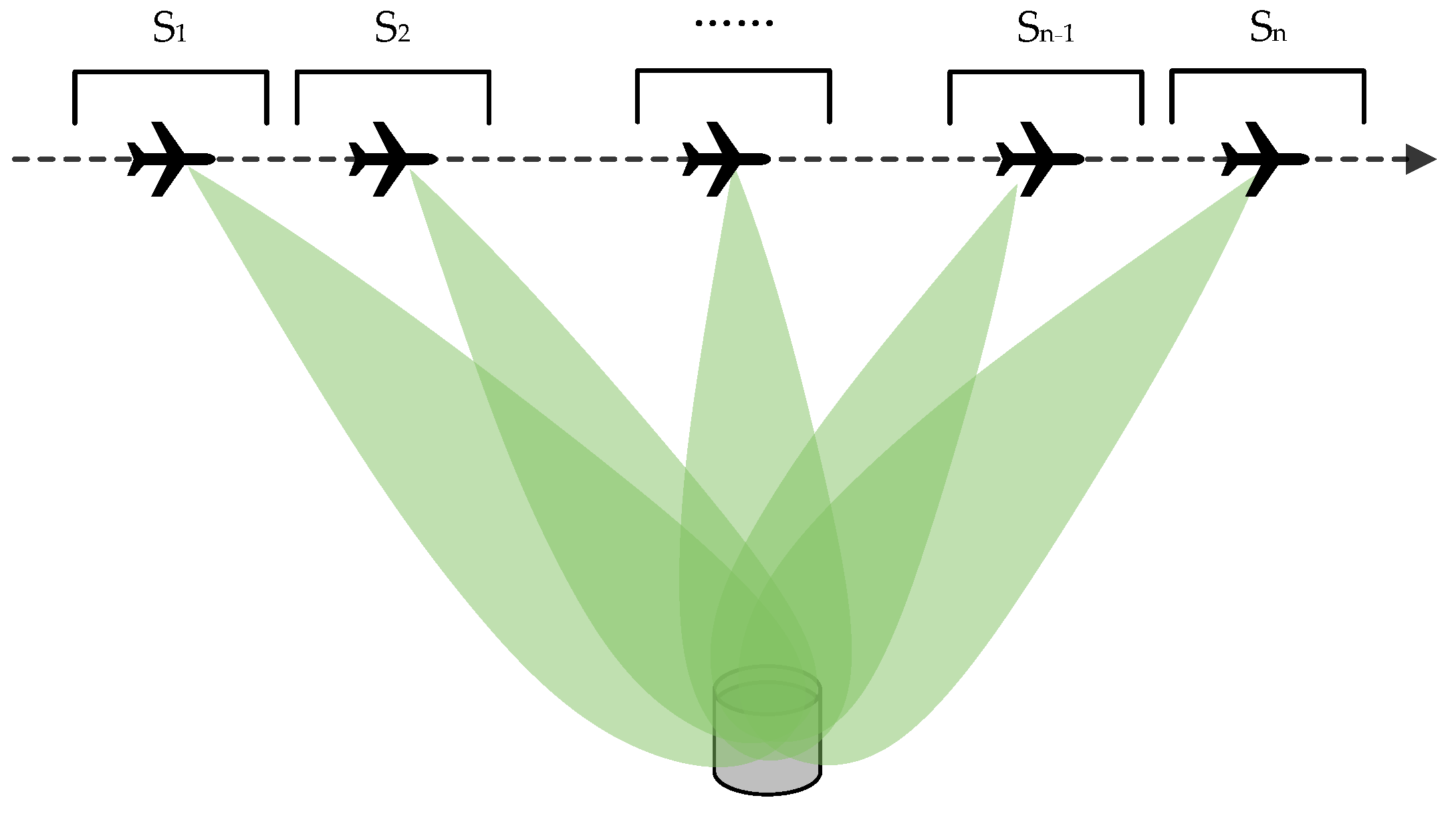
This paper proposes a new multipath ghost image suppression method through multi-aspect observation. This method can suppress the multipath ghost image of complex structure targets. The radar observes the same scene from various aspect angles to obtain multi-aspect image sequences. Then, the target image and the multipath ghost image are separated based on their different characteristics from each other. This paper takes an external floating roof oil tank as an example to analyze the multipath ghost image characteristics of the oil tank. The multipath ghost image rotates with the aspect angles, whereas the scattering center of the target image does not. This paper applies the idea of principal component analysis to multipath ghost image decomposition and analyzes two principal component analysis methods based on PCA [25,26,27] and RPCA [28,29]. The matrix decomposition rule of the two methods is different. Through research and analysis, RPCA is more suitable for multipath suppression of complex structural targets.
This article’s remaining chapters are arranged as follows. The geometry model of SAR multi-aspect observation, the radar imaging model, and the multi-aspect multipath signal characteristics of oil tanks are introduced in Section 2. In Section 3, the multipath ghost image suppression method based on the principal component analysis is presented. The principles and distinctions between PCA and RPCA for multipath suppression are also analyzed and contrasted. In Section 4, the data based on real airborne multi-aspect SAR observation of oil tanks are used to verify the multipath ghost image suppression effect of the method proposed in this article. Conclusions are described in Section 5.

2. Multipath Signal Characteristics

2.1. Observation Geometry Model

The multi-aspect observation of airborne SAR is shown in Figure 1. The linear flight spotlight imaging mode is adopted in this paper. The radar antenna observes the chosen area sideways at a specific incident angle, whereas the aircraft platform flies in a uniform straight line at a specific height in the air. In order to gather continuous observation data of the scene while the aircraft is in flight, the beam constantly points to the center of the same scene and transmits and receives the echo signal at a specific pulse repetition frequency. The target’s continuous observation aspect must reach tens of degrees. Following the acquisition of the echo signals, they are segmented into sub-apertures, and then a sequence of images at various observation aspect angles is synthesized, which are recorded as s n , where the subscript n is the sub-aperture sequence number, n = 1 , 2 , , N , N is the number of sub-apertures.

2.2. Radar Imaging Model

Taking the chirp signal system as an example, the signal transmitted by the antenna is [30]
s t t = r e c t t T p exp j 2 π f c t + j π k t 2
where the function r e c t   represents the rectangular wave, t is the fast time, f c is the working frequency, k is the frequency modulation, and T p is the pulse length of the linear frequency modulation signal.
Assume that the coordinate of the point target P is x p , y p , z p and the coordinate of the antenna phase center is x a , y a , z a . Then, the distance from the radar to P is expressed as
R p , a θ = x a θ x p 2 + y a θ y p 2 + z a θ z p 2
where θ is the azimuth angle.
After IQ demodulation of the point target P’s echo signal, the baseband signal is
s a t , θ = σ p · r e c t t 2 R p , a θ c T p · exp j 4 π f c c R p , a θ + j π k t 2 R p , a θ c 2
where σ p is the target scattering coefficient, c is the lightspeed.
Perform fast time Fourier transform on Formula (3) and transform it to the range frequency domain. The signal expression is
S a f , θ = σ p · exp j 4 π f c + f c R p , a θ j π f 2 k
Formula (4) is multiplied by the frequency domain matched filter to complete the range compression. The expression of the frequency domain matched filter is
H r c f = exp j π f 2 k
Assume K r = 4 π f + f c / c is the two-way wavenumber. After matched filtering, the expression of the range frequency domain signal is
S a K r , θ = σ p · exp j K r R p , a θ
A back-projection algorithm is used to obtain accurate sub-aperture images. The expression of the sub-aperture image is
g a , n x , y , h 0 = n 1 Δ θ n Δ θ K r = K min K max S a K r , θ · exp j K r R a θ , x , y , h 0 d K r d θ
where n is the sub-aperture index, h 0 is the imaging plane elevation, x , y is the imaging plane pixel coordinate, Δ θ is the sub-aperture angle size, K min and K max are the minimum and maximum values of wavenumber K r respectively, and R a θ , x , y , h 0 is the distance from the antenna phase center to coordinate x , y , h 0 .

2.3. Analysis of Multipath Signal Characteristics

This paper uses the floating roof oil tank as an example to analyze the properties of multipath ghost images in multi-aspect image sequences. The schematic diagram of the external floating roof tank structure is shown in Figure 2a. The main structure includes a cylindrical tank barrel and a circular top cover. The top cover is close to the oil storage surface and can float up and down in response to changes in liquid level to reduce oil evaporation loss. A large number of fine cylindrical vent valves are distributed on the top cover to balance the air pressure. The top of the oil tank barrel is connected to the top cover by a ladder, and a maintenance walkway is arranged on the top of the oil tank barrel for maintenance personnel. The Google optical image of the external floating roof oil tank area is shown in Figure 2b. The airborne SAR observation geometry is shown in Figure 2c. Figure 2d displays the sub-aperture image of the external floating roof oil tank that was obtained using airborne SAR. The image is X-band and the resolution is about 0.2 m. Next, the scattering characteristics of the oil tank in the image are analyzed based on the geometric structure characteristics.
(1) As shown in Figure 3a, the maintenance walkway atop the oil tank forms a dihedral structure with the outer wall of the oil tank, resulting in the formation of an arc-shaped bright line in the image. It is marked with a red line in Figure 3b, which is a real scattering center. According to the principle of range-Doppler imaging of SAR, when radar observes, the target with the same distance and the same angle to the radar is projected to the same position. An equidistant line is marked by a blue line in Figure 3a. The point O in Figure 3a will be projected to the position of O in the image. Points at other locations will also be projected onto the ground plane based on the same principle, so they form an arc in the image. The target structure shown in Figure 3a is close to the radar and is located at the near end of the distance during imaging.
(2) As depicted in Figure 4a, a dihedral structure is formed by the oil tank wall and the ground, with the scattering center positioned at the intersection line of the oil tank wall and the ground. This configuration gives rise to an arc-shaped bright line in the SAR image, denoted by a red line in Figure 4b, identifying it as a real scattering center. Following the range-Doppler imaging principle of SAR, the arc-shaped bright line is situated slightly farther away than the one formed by the maintenance walkway.
(3) As shown in Figure 5a, the radar signal undergoes direct reflection from the outer wall of the oil tank, constituting a surface reflection. This reflection exhibits significantly weaker energy compared to the dihedral reflection, resulting in the formation of a moon-shaped area in the image. This region is highlighted by a red area in Figure 5b, confirming it as the real scattering center. Since the distance of the signal reflection path is between the ground dihedral angle and the top maintenance walkway dihedral angle, the scattered signal is the area between the two arc-shaped bright lines.
(4) As depicted in Figure 6a, a dihedral corner reflector is formed by the circular top cover of the oil tank and the inner wall of the oil tank. The radar signal undergoes dihedral reflection between the floating roof and the inner wall, which again leads to the bright arc-shaped line during imaging. The bright arc-shaped line is marked as a red line in Figure 6b, and it is an actual scattering center. The numbers in Figure 6b are the labels of the oil tanks. Following the range-Doppler imaging principle of SAR, the arc-shaped bright line is positioned at the far end of the distance. Notably, as the oil quantity decreases, the distance increases. Leveraging this principle, it can be deduced that the oil storage capacity of Tank No. 1 in the image is the smallest, whereas Tanks No. 2 and No. 3 have larger capacities, and the oil storage capacity of Tank No. 4 falls between them.
(5) As illustrated in Figure 7a, the vent valves positioned above the circular top cover manifest as small cylindrical structures, forming a dihedral corner reflector with the surface of the top cover. They appear as bright spots in the image, marked as red points in Figure 7b, which are real scattering centers. Due to the obstruction of the proximal barrel wall, the vent valve in the proximal part cannot be observed; that is, the part to the left of the green dotted line in the figure. As the oil storage volume decreases, the unobservable area of the top cover becomes larger.
(6) When there is less oil stored in the tank, the radar signal has more complex multiple reflections in the oil tank. In [11], SBR was used to simulate multipath scattering in oil tank SAR images. The principal multipath propagation path within the oil tank is illustrated in Figure 8a. It is evident that the electromagnetic wave signal undergoes multiple reflections between the inner wall and the floating roof. As illustrated in Figure 9, when the tangent direction of the reflection point is perpendicular to the incident direction, as seen at point A, the multipath reflection path is the longest. The position of point A in SAR image is also farther, that is, the position of point A′. In contrast, the multipath paths at points B and C are shorter. Consequently, the resulting multipath ghost image in the figure exhibits a moon-shaped pattern, highlighted in the red area in Figure 8b. This particular type of multipath ghost image possesses considerable energy and area, exerting potent interference on the image. Consequently, it becomes the focal point of suppression efforts in this study.

3. Multi-Aspect Observation Multipath Suppression

3.1. The Basic Principle of Multi-Aspcet Observation Multipath Suppression

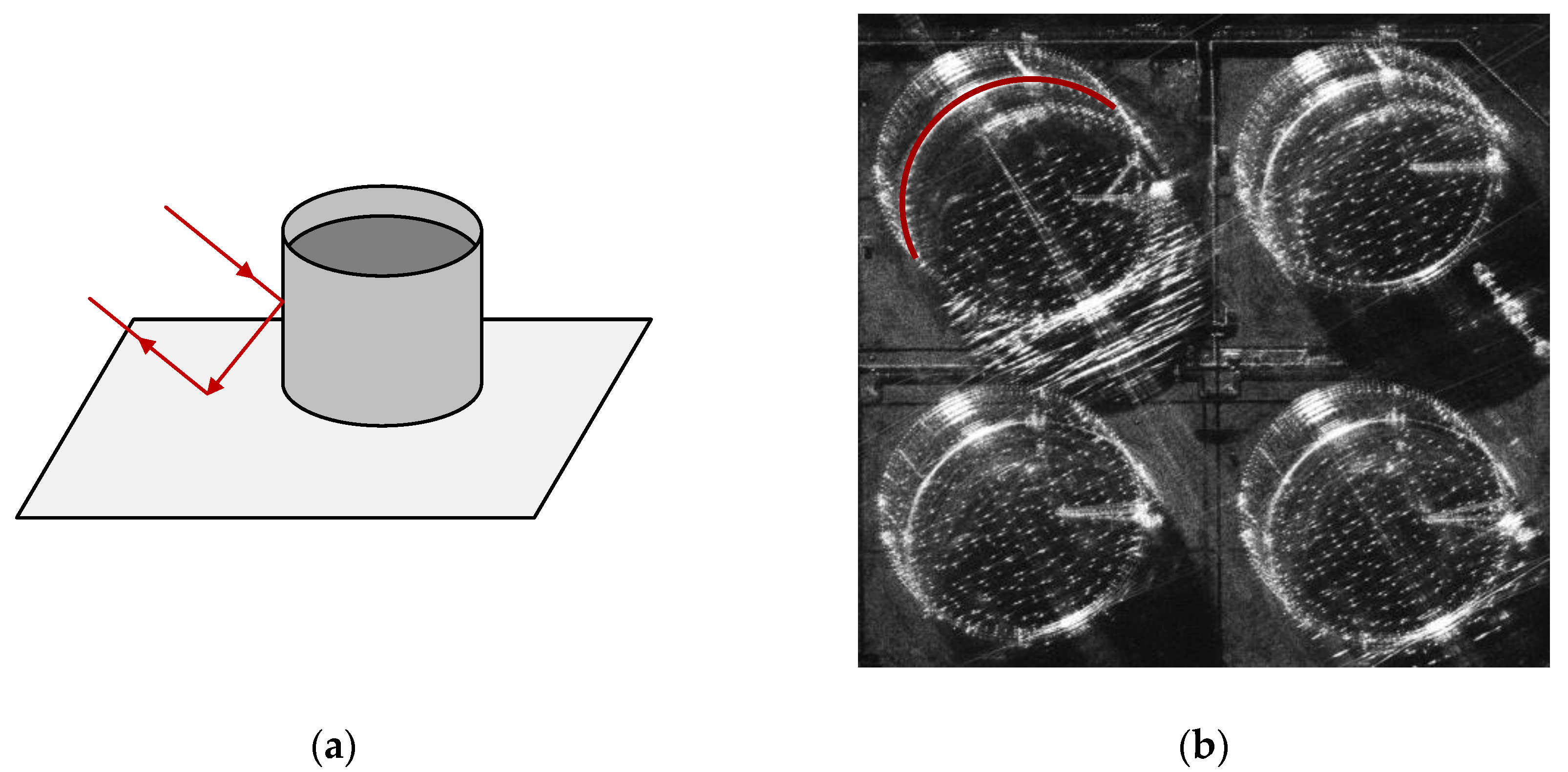
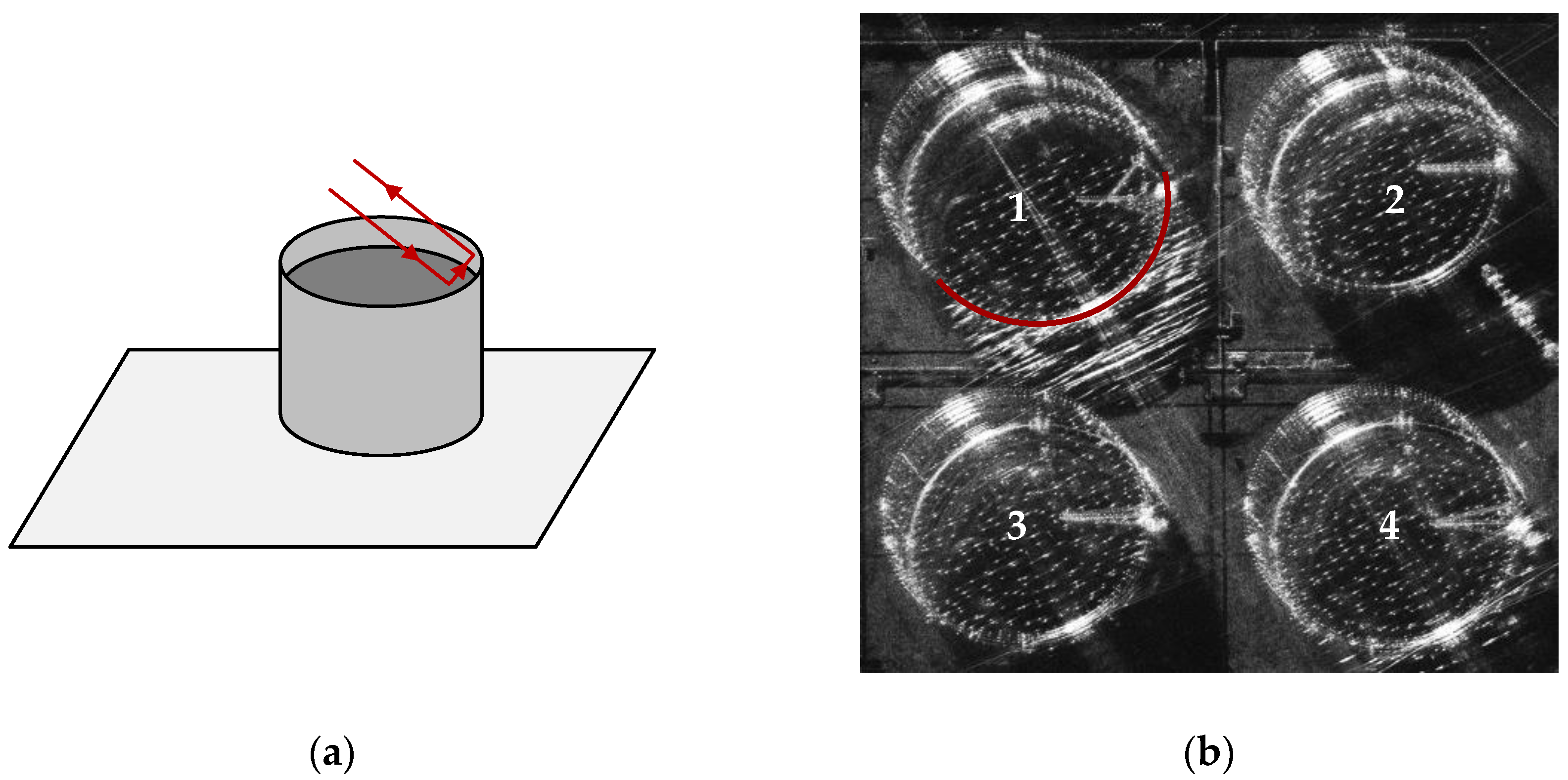
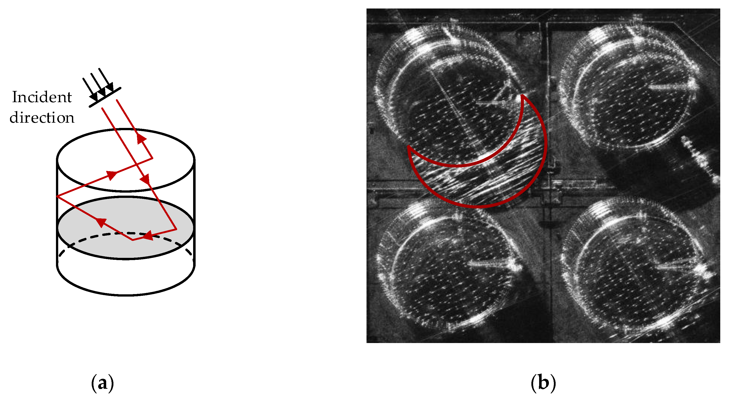
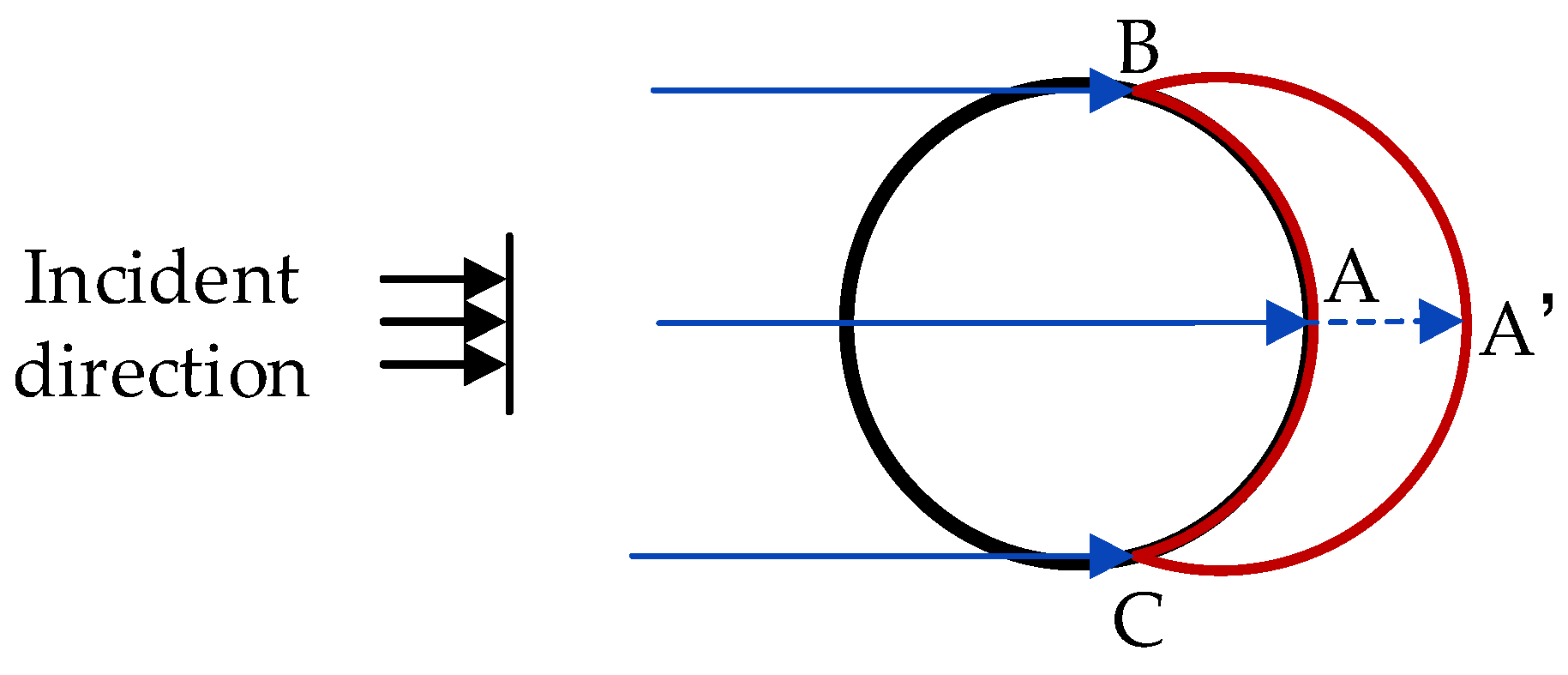
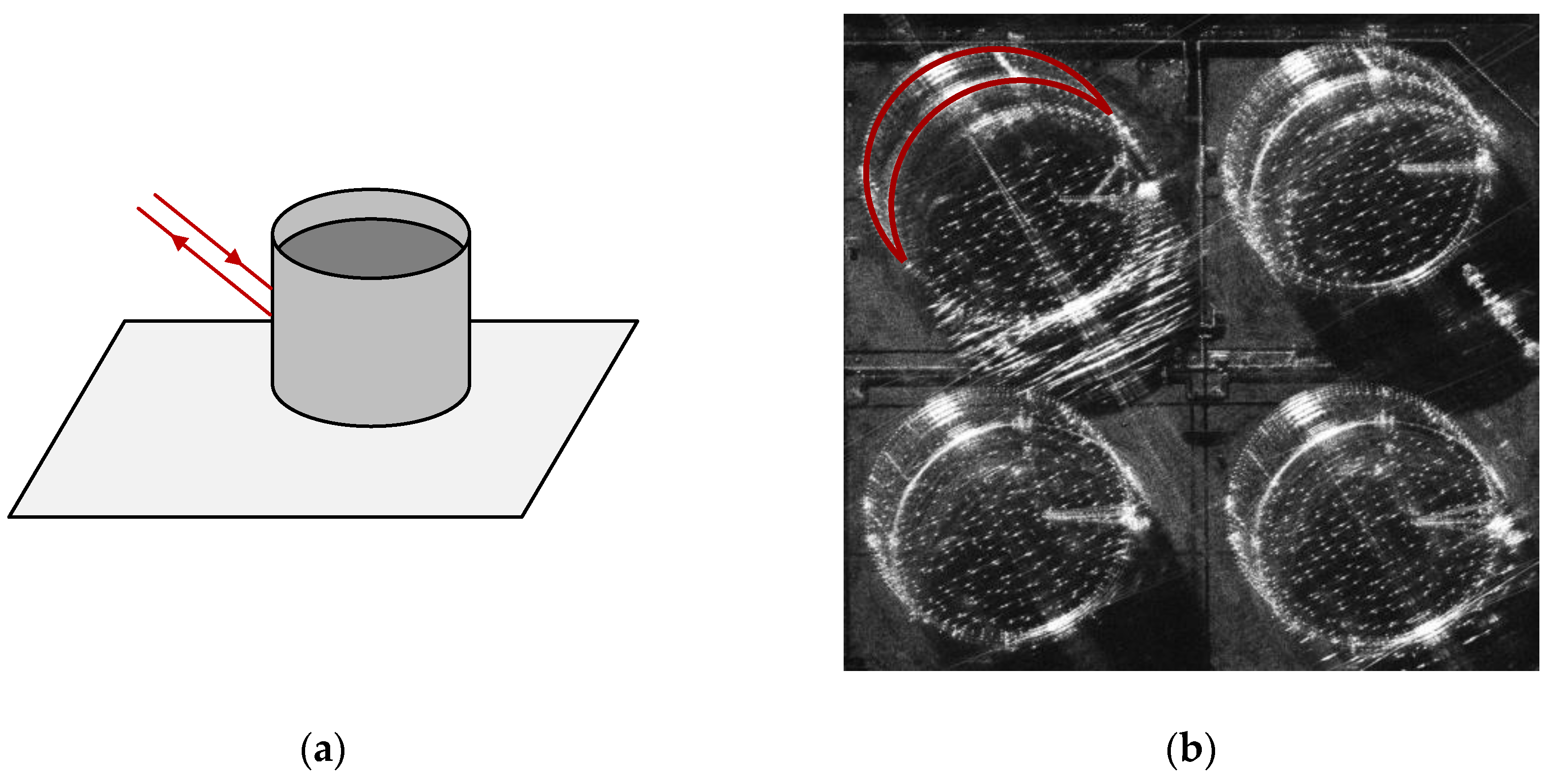
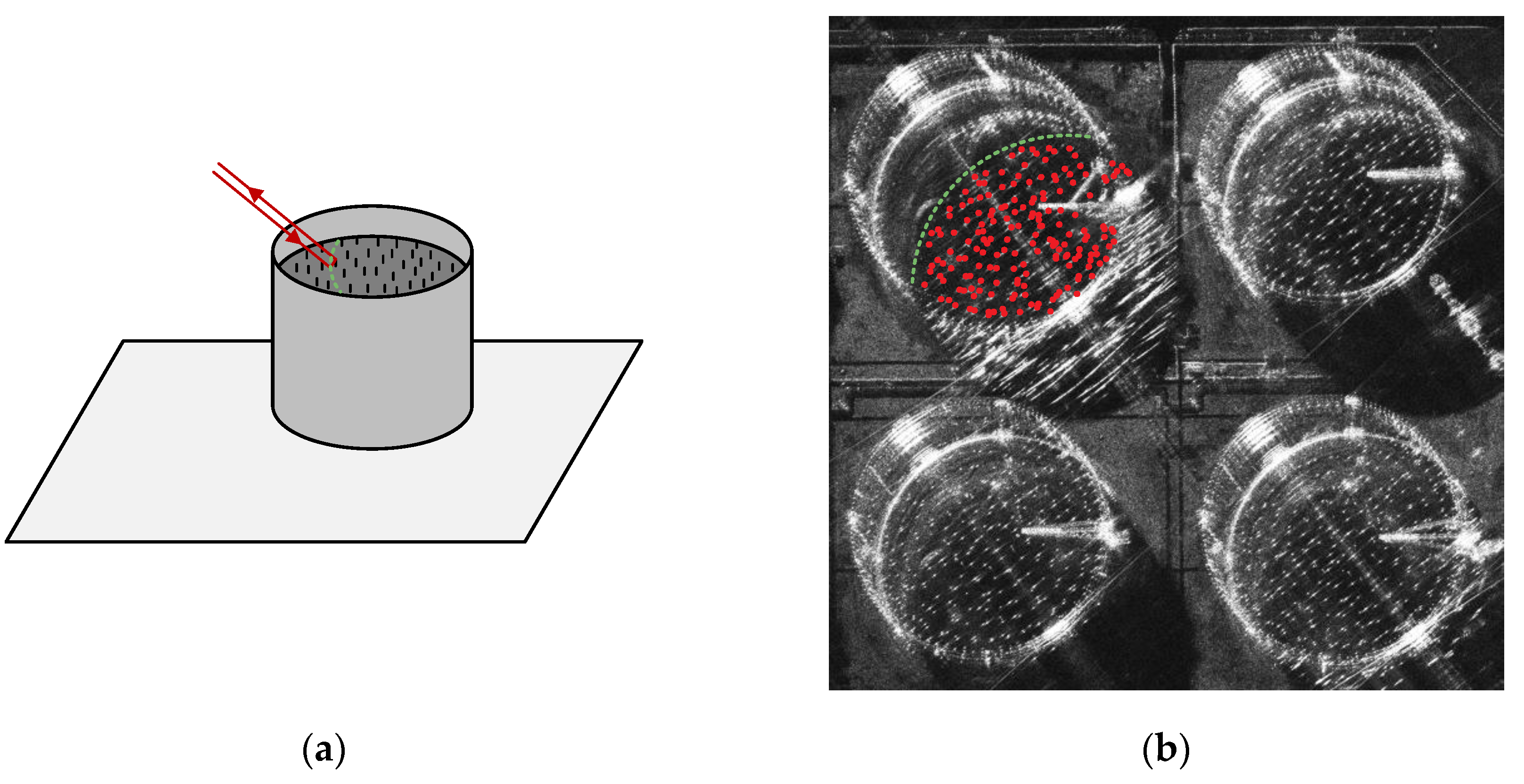
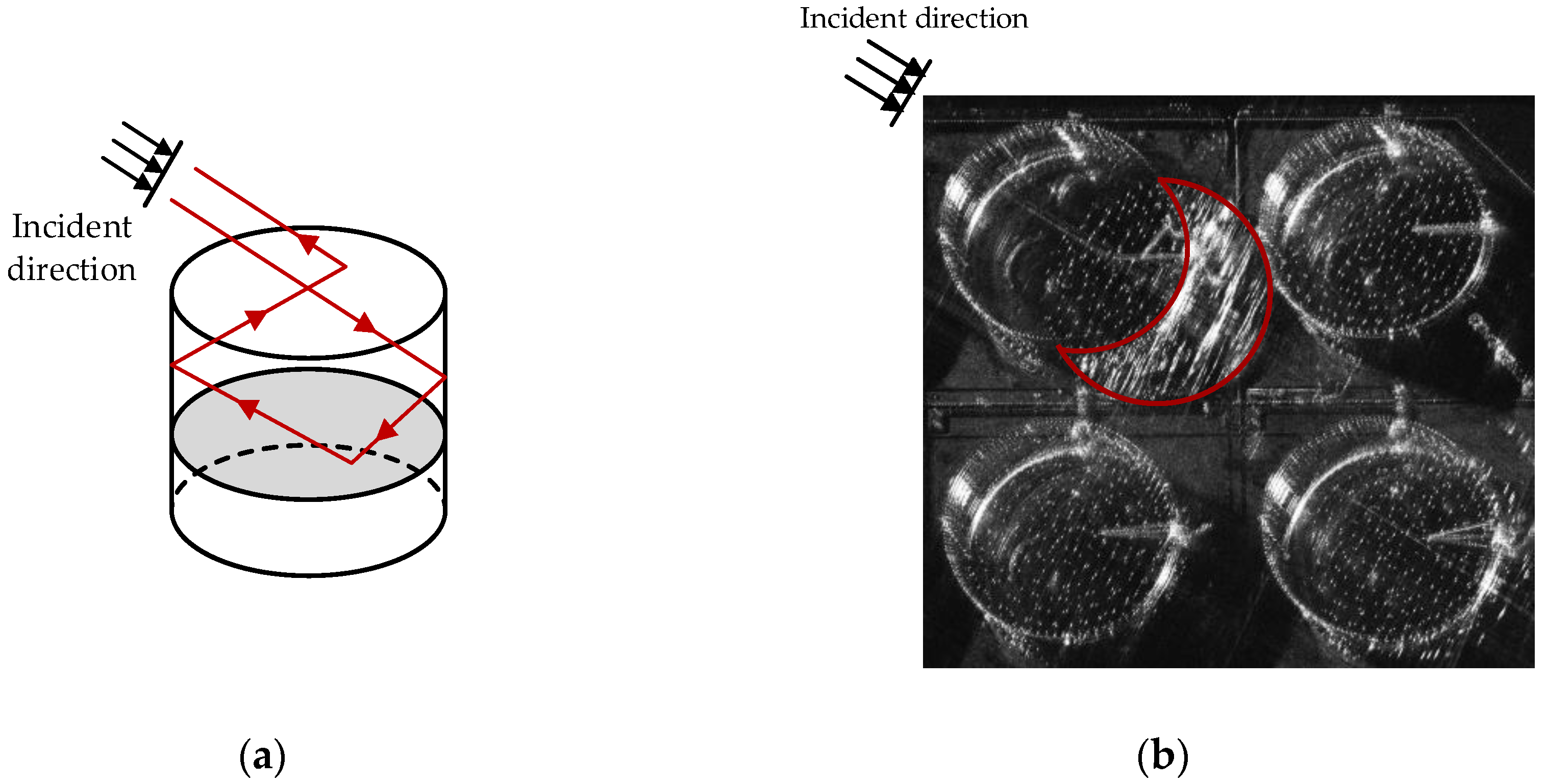
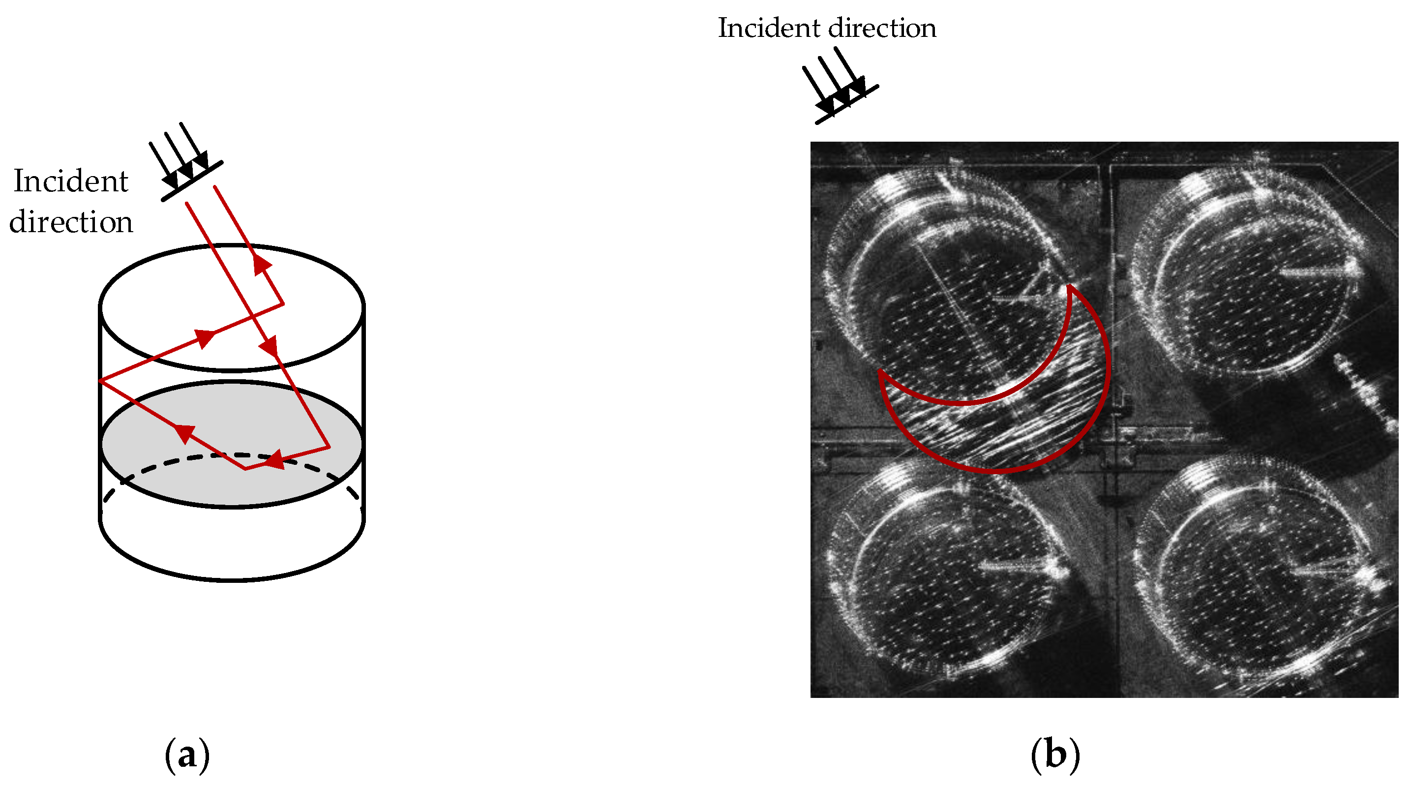
This section analyzes the radar signal propagation path and imaging characteristics of external floating roof oil tanks during multi-aspect observation. From the analysis in the previous section, it can be seen that there are mainly two types of reflections inside the oil tank. They are dihedral reflections and multiple reflections of radar signals produced between the inner wall of the oil tank and the external floating roof. Dihedral reflection reflects the real target scattering center in the image, whereas multiple reflections are the cause of multipath ghost images. This section mainly analyzes the relationship between the multipath ghost images inside the oil tank and the observation azimuth.
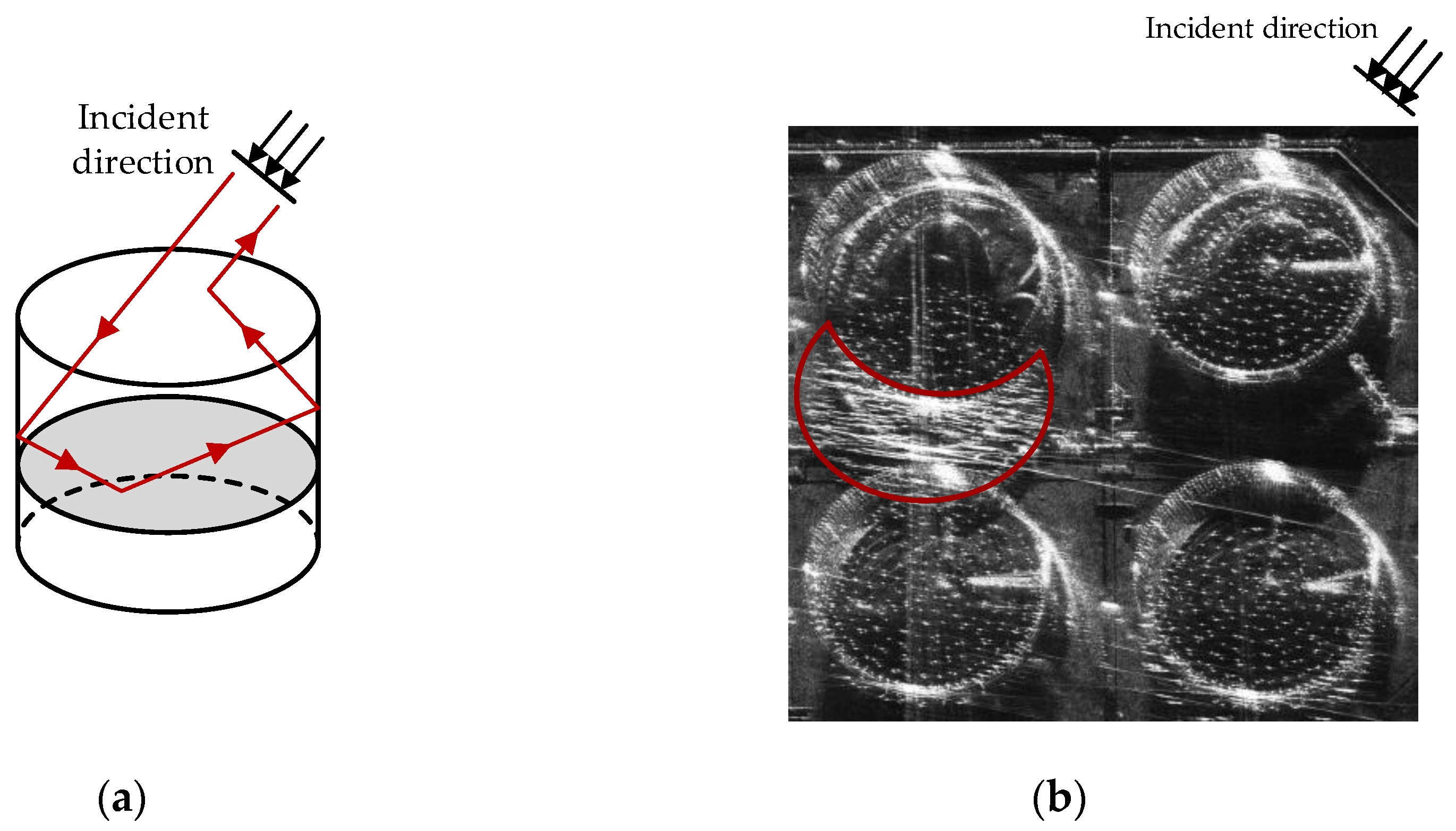
Figure 10, Figure 11 and Figure 12, respectively, show the propagation path of multiple reflections of electromagnetic waves inside the oil tank when observed at different azimuth angles. It can be seen from the oil tank’s SAR images that as the observation aspect changes, the position of the ghost image will change accordingly. The greater the difference in aspect, the greater the difference in position of the multipath ghost image. The structure of the oil tank is a centrally symmetrical structure about the central axis. Thus, the changing pattern of multipath ghost image position is that it rotates with the change in observation aspect. However, the position of the real target scattering center does not change with the observation aspect. Therefore, the multi-aspect characteristic differences between real scattering centers and multipath ghost images can be used to separate them.

3.2. Multi-Aspect Observation Multipath Suppression Method Based on PCA

This paper proposes to decompose real target images and multipath ghost images based on the idea of principal component analysis. PCA is a classic algorithm for principal component analysis. This section will evaluate its effectiveness in suppressing multipath ghost images in multi-aspect observations.
Figure 13 shows the schematic diagram of the multi-aspect observation multipath ghost image suppression method based on PCA. In the figure, the number of sub-images n = 3 is taken as an example; x 1 , x 2 , x 3 , respectively, represent the amplitude values of three sub-images, and each scatter point represents each pixel sample. The real target image pixels’ amplitude values change little with the aspect and they are distributed in the direction of the principal component vector. However, the multipath ghost image pixels’ amplitude values change greatly with the aspect and they deviate from the direction of the principal component. The point P in the image represents the pixel point that the multi-aspect sequence deviates greatly from the direction of the principal component.
The PCA decomposition process is described as follows: First, the sequence images s n of different observation aspects are vectorized to form a matrix X . The size of X is M L   ×   n , where M and L are the image sizes. Then perform singular value decomposition on X ,
X = U Σ V T
where Σ is the diagonal matrix of singular values, and U and V are eigenvectors, respectively.
In the application scenario of this paper, the principal component direction is the feature vector v 1 , corresponding to the maximum singular value σ 1 , and the projection value of the sequence image in the principal component direction is u 1 . After matrix decomposition, it is divided into two parts. The first part is the orthogonal projection component of the principal component direction:
X 1 = σ 1 u 1 v 1 T
The second part is the component in the non-principal component direction:
X 2 = X X 1
Here is an example to illustrate. The pixel point P deviates from the stable value in the third sub-aperture image due to multipath interference, as shown in Figure 13. According to the principle of PCA, PCA obtains the direction of the data’s maximum variance by orthogonally decomposing; that is, the direction of the principal component. After orthogonal decomposition, the amplitude value of the pixel point P is orthogonally projected to the principal component direction. The projection point is P , but the ideal value is P . Therefore, target energy loss and multipath signal residue will result from directly employing the PCA approach to orthogonally partition the data.
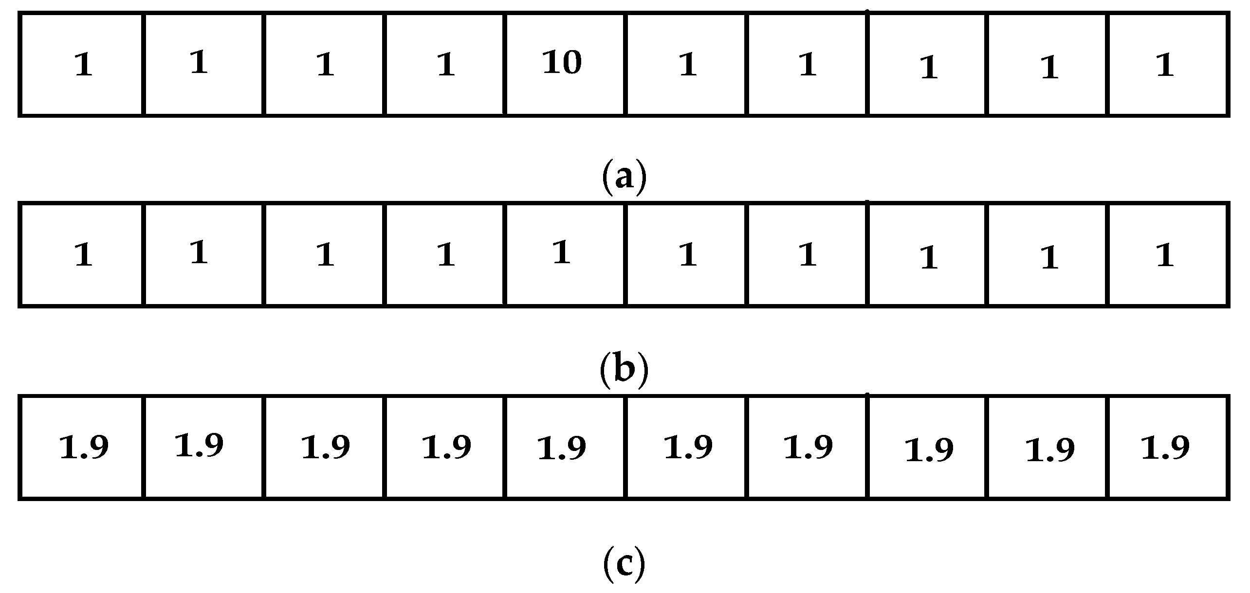
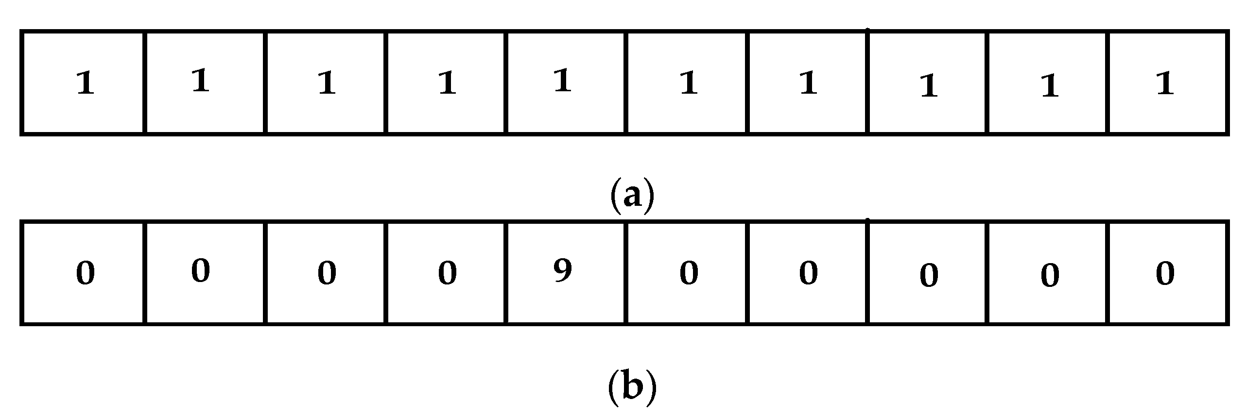
An example of a certain pixel’s amplitude sequence before and after PCA decomposition is shown in Figure 14. There are ten sub-image sequences in this sample. This pixel has a large amplitude value in sub-image 5 due to the influence of multipath ghost images, assumed to be 10. There is no multipath ghost image in other sub-apertures, and the amplitude value is set to 1, as shown in Figure 14a. The ideal value of multipath suppression is to obtain a sequence of all 1 s, as shown in Figure 14b. Nevertheless, the sequence value obtained after PCA decomposition is displayed in Figure 14c, and the multipath signal is not effectively suppressed. Therefore, multipath signal suppression cannot be directly addressed by the PCA method.

3.3. Multi-Angle Observation Multipath Suppression Method Based on RPCA

RPCA is also a matrix decomposition method based on the idea of principal component analysis. The biggest difference between RPCA and PCA is that RPCA uses sparse decomposition. RPCA decomposes the original data matrix X into two parts: low-rank matrix A and sparse matrix E . The model is as follows:
min   A , E r a n k A + λ | | E | | 0 , s . t . X = A + E
where r a n k is the rank of the matrix and | |   | | 0 is the 0 norm. The above formula must be loosened because this problem’s optimization is an NP problem. Usually, the 1 norm is used to perform convex relaxation on the 0 norm, and the matrix rank is approximated by the nuclear norm. The above problem is transformed into solving the following model.
min A , E | | A | | + λ | | E | | 1 ,   s . t . X = A + E , λ = c max ( m , n )
where | | A | | represents the nuclear norm of matrix A ; that is, the sum of singular values of matrix A . ( m , n ) is the dimension of the matrix, and c is a constant.
This paper proposes a multi-aspect multipath suppression method based on RPCA. The principle involves using the stability characteristics of the real target signal and the sparse variation characteristics exhibited by multipath ghost images from different aspects to separate them. The radar acquires a sequence of SAR images by observing the same target from various aspects. Due to the stable nature of real targets, their multi-aspect image sequence exhibits low-rank characteristics. On the other hand, the positions of multipath ghost images vary across the multi-aspect SAR image sequence, so the number of sequences with multipath interference for each pixel is sparse. The multi-aspect image sequence of multipath ghost images exhibits sparse characteristics. RPCA is employed for the purpose of conducting a low-rank and sparse decomposition of the signal. The resulting low-rank matrix represents the stable principal component, retaining information pertaining to the real target. Simultaneously, the sparse matrix represents variation deviating from the principal component, which stores the information of the multipath ghost image. By reconstructing the decomposed low-rank matrix and sparse matrix, respectively, the SAR image after multipath ghost image suppression and the multipath ghost image can be obtained, respectively.
Unlike PCA, RPCA does not separate stable principal components and changing signals through orthogonal decomposition. For points that deviate from the principal component direction, RPCA does not restore them through orthogonal mapping. RPCA decomposes the signal through regularization constraints of low rank and sparseness, which can more accurately separate the target signal and multipath ghost images. Based on this principle, when RPCA processes the pixel P signal affected by multipath interference in Figure 14, it can accurately restore it to P .
The following example illustrates. RPCA decomposition is applied to the example shown in Figure 14 from the preceding section, with the aim of extracting the low-rank and sparse components for a designated pixel. As shown in Figure 15, (a) is the low-rank part of RPCA decomposition, and (b) is the sparse part after decomposition. It is evident that RPCA accurately distinguishes between stable and dynamic components of the deviated pixels when there are pixels in the matrix that deviate from the principal component direction.
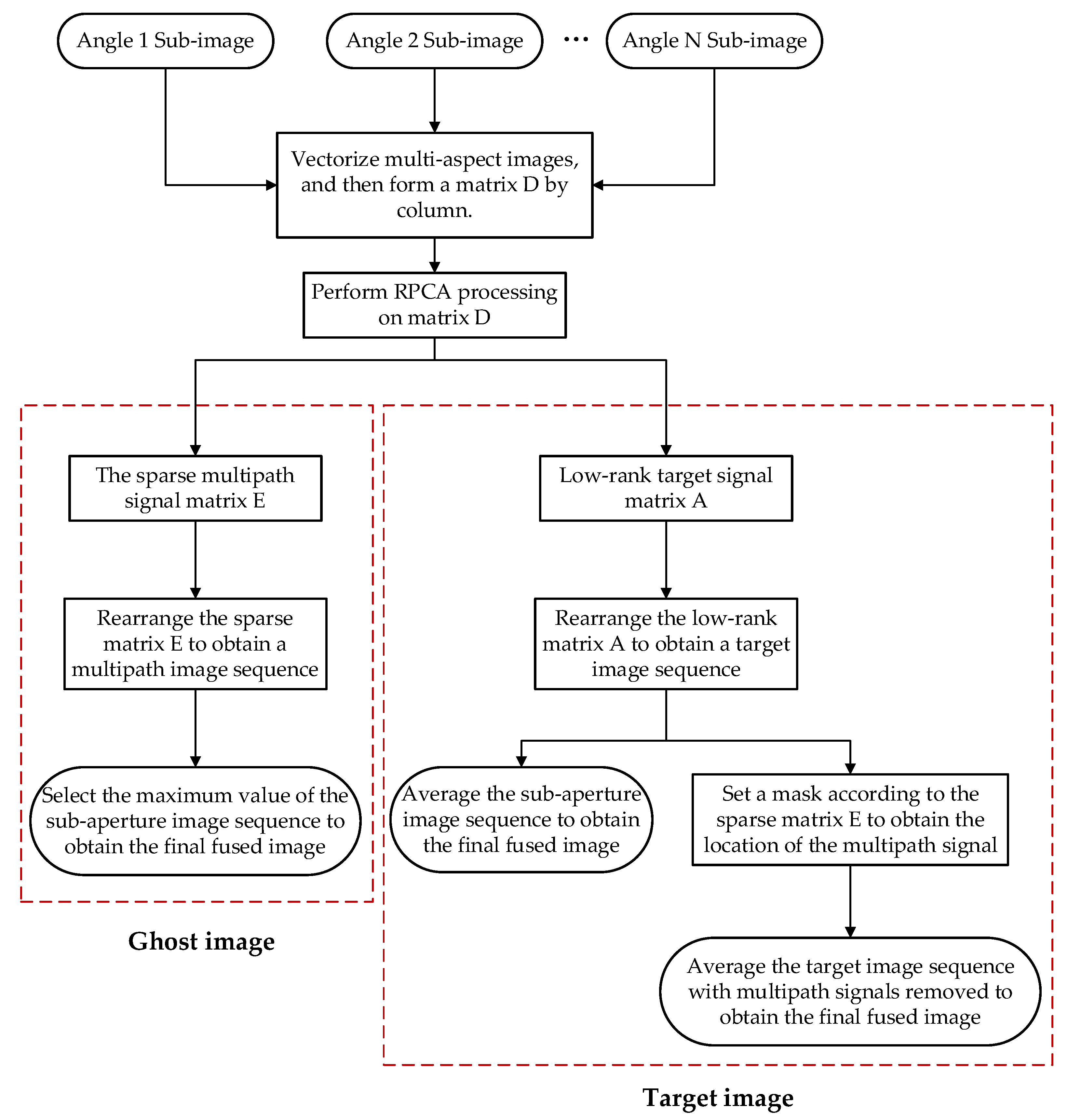
The process of the multipath ghost image suppression method based on RPCA is shown in Figure 16. The specific steps are as follows:
Step 1: Multi-aspect images are vectorized and formed into a matrix by column.
Step 2: RPCA is used to decompose the matrix, yielding a low-rank matrix A and a sparse matrix E .
Step 3: The low-rank matrix A and the sparse matrix E are, respectively, rearranged to obtain the target image sequence and the multipath image sequence.
Step 4: Average the sub-aperture image sequence to obtain the final fused image.
Step 5: Set a mask based on the sparse matrix E to remove multipath signals so that the remaining multipath signals at the corresponding positions in the low-rank matrix A can be removed.
Typically, the multipath signal energy of complex structure targets is strong and the area is large. Despite the application of RPCA processing, the low-rank matrix still retains residual multipath signals. To enhance the effectiveness of multipath suppression, this paper introduces a masking approach described in step 5 before sequence image fusion. The mask is generated based on the sparse matrix E , where each ‘1’ in the mask corresponds to a ‘0’ element in E, and conversely, each ‘0’ in the mask corresponds to a non-zero element in E. This method effectively eliminates the influence of residual multipath pixels during sequence image fusion.

4. Experimental Verification

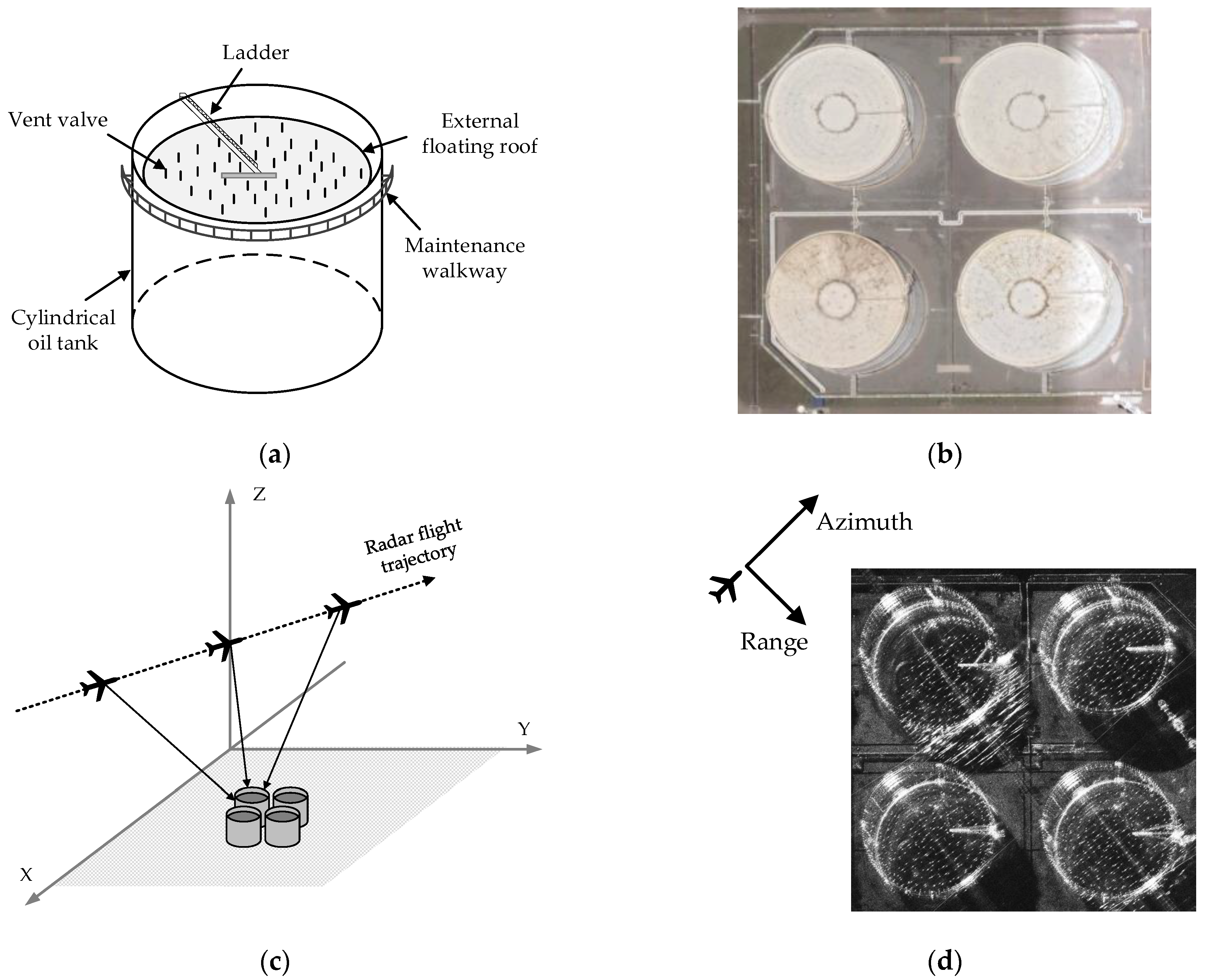
In this section, the data based on an actual airborne multi-aspect SAR observation of oil tanks are used to verify the multipath ghost image suppression effect of the method proposed in this article. The observation area is located in Zhejiang Province, China.
In the experiment, an airborne SAR system was used to observe external floating roof oil tanks. The observation geometry is the same as Figure 1, and the experimental parameters are shown in Table 1. The data were acquired with an observed azimuth of ±44° and a sub-aperture synthetic aperture angle of 8°. The image sequence consisted of 11 images.
PCA and RPCA decomposition techniques are employed to break down the oil tank sequence images. Stable components in the principal component direction and unstable components can be obtained. Figure 17 and Figure 18, respectively, show the decomposed results of three of the sub-images.
Three of the sub-images are shown in column (a) of Figure 17, the stable principal component acquired through PCA decomposition is shown in column (b), and the unstable component obtained through PCA decomposition is shown in column (c). PCA uses orthogonal decomposition to obtain stable principal components. The components in the principal component directions of different sub-images are the same, so it can be seen that the principal component images in column (b) are the same. There are more multipath ghost images remaining, which are framed by the red arc in the figure. The unstable components in different sub-images vary with the observation aspect, as shown in column (c). PCA decomposition is inaccurate in extracting multipath signals, and unstable components will affect other stable components, resulting in target energy loss and multipath signal residue.
Figure 18 shows the results of RPCA decomposition. The parameter λ is set to 1.7. Three of the sub-images are shown in column (a), and the stable low-rank images with RPCA decomposition are shown in column (b). Although the majority of the multipath ghost images are suppressed, some multipath ghost images remain because of their enormous energy and large area. Sparse images obtained by RPCA decomposition are displayed in column (c), which extract the multipath signals that vary with the observation aspect.
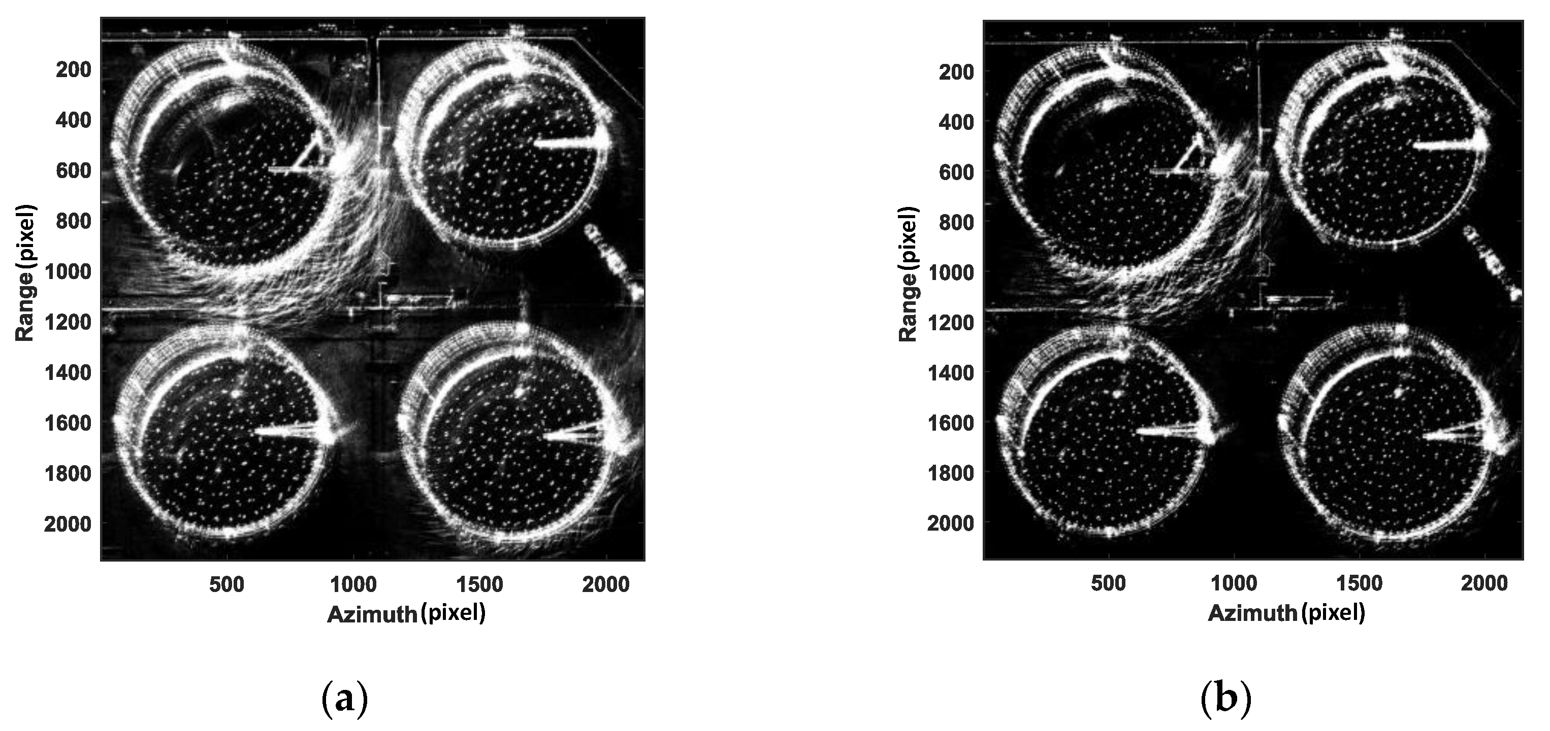
The final fused image is obtained by summing the decomposed sequence images, as illustrated in Figure 19. It is evident that the image processed using the PCA method still exhibits a significant presence of multipath ghost images. This occurs because the PCA method obtains the stable principal component of the image through orthogonal decomposition. The specific method is to vertically project pixels deviating from the principal component onto the principal component direction. This approach struggles to effectively suppress multipath interference and results in the loss of target information. In contrast, the RPCA method conducts low-rank and sparse decomposition of the multi-aspect image matrix, effectively suppressing multipath ghost images while preserving the target image. Although there are still residual multipath ghost images, the suppression effect is significantly better than that of the PCA method. Figure 19b is the non-principal component image obtained after PCA decomposition, and Figure 19d is the sparse image obtained after RPCA decomposition. Both images represent the part of the image that deviates from the principal component; that is, the signal that varies with aspect, mainly including multipath signals, sidelobes, anisotropic signals, etc. It can be seen that Figure 19d extracts more multipath signals than Figure 19b, indicating that the RPCA method has a better multipath suppression effect.
Based on the analysis in the preceding section, it is evident that the sparse matrix E , acquired through RPCA decomposition, contains the information of multipath ghost images. The mask is set according to the sparse matrix E . The 1 in the mask corresponds to the 0 element in E, and the 0 in the mask corresponds to the non-zero element in E . The sequence images obtained after masking are added. The result is shown in Figure 20, which more effectively suppresses multipath ghost images.
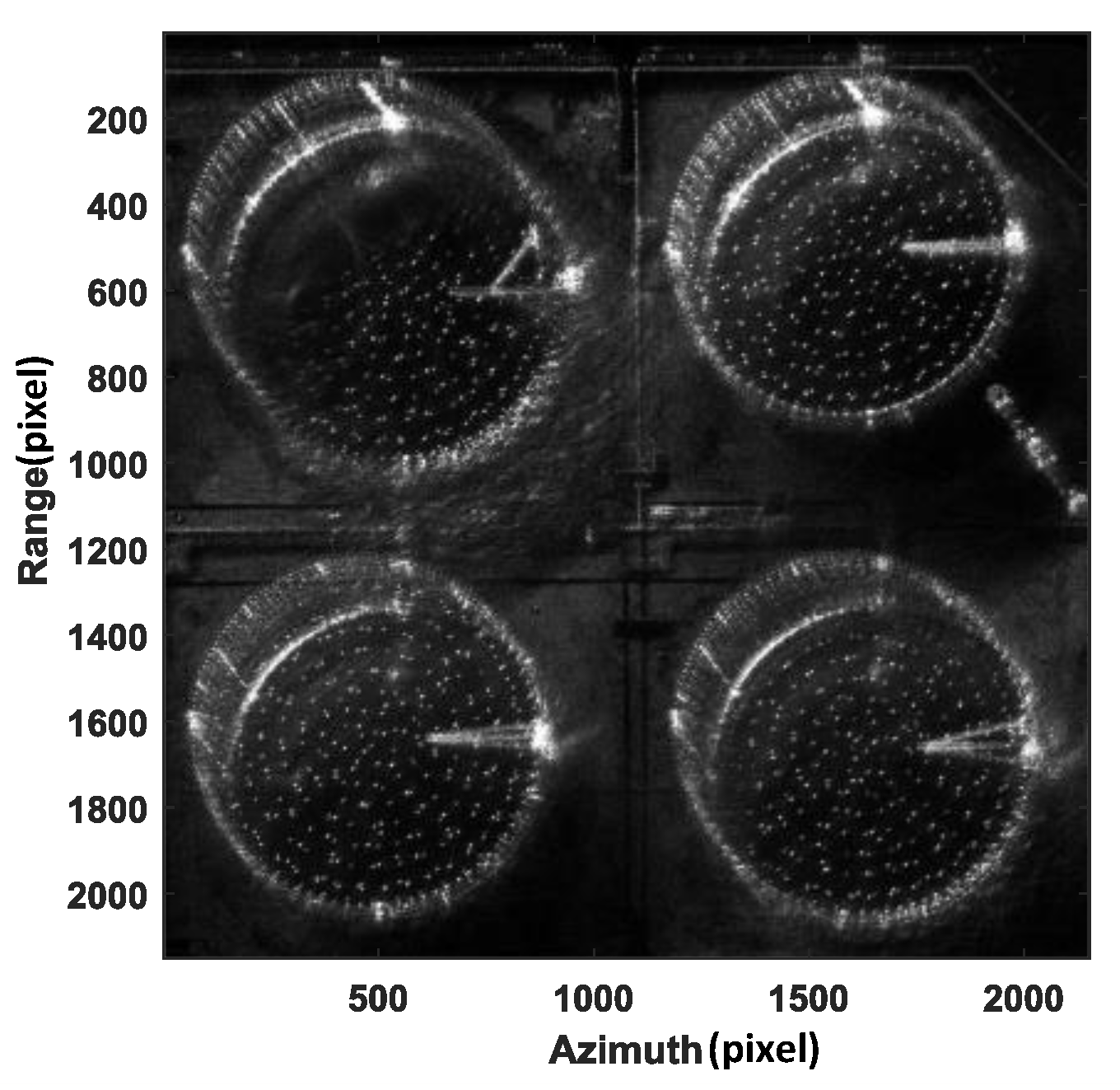
In order to verify the algorithm presented in this paper, we compare it with existing sub-aperture fusion methods. The sub-aperture fusion method proposed in [22] first adds sequence images to create a full-aperture image. Next, the sub-aperture images of different aspects are dot-multiplied with the full-aperture image and then added. The processing result of the oil tank data is shown in Figure 21a. It is evident that the multipath ghost image was not effectively suppressed, and the information of the weak scattering area was lost. The sub-aperture double-layer fusion method proposed in [23] adds a layer of fusion based on the original sub-aperture fusion method. This method first multiplies the sub-aperture images at different aspects with the full-aperture image to obtain the first layer fusion image. In the second layer fusion, the first layer sequence images are divided into multiple groups, and the images in different groups are correspondingly added to enhance the target image. The added images are then dot multiplied to suppress multipath ghost images. The result of processing the oil tank data with the sub-aperture double-layer fusion method is displayed in Figure 21b. The suppression effect of multipath ghost images is better than that of the single-layer sub-aperture fusion method. However, some multipath ghost images still remain and the information loss in weak scattering areas is more serious. Generally speaking, the sub-aperture fusion method can suppress the ghost image’s energy and increase the target’s energy. This is achieved by simultaneously increasing the pixel amplitude values of the target image and decreasing the pixel amplitude values of the multipath ghost image. But it cannot accurately identify the multipath ghost image and the real target. In the application context of this article, this type of method has a certain multipath suppression effect, but there are many multipath ghost images remaining, and the energy of the weak scattering region with stable scattering is lost.
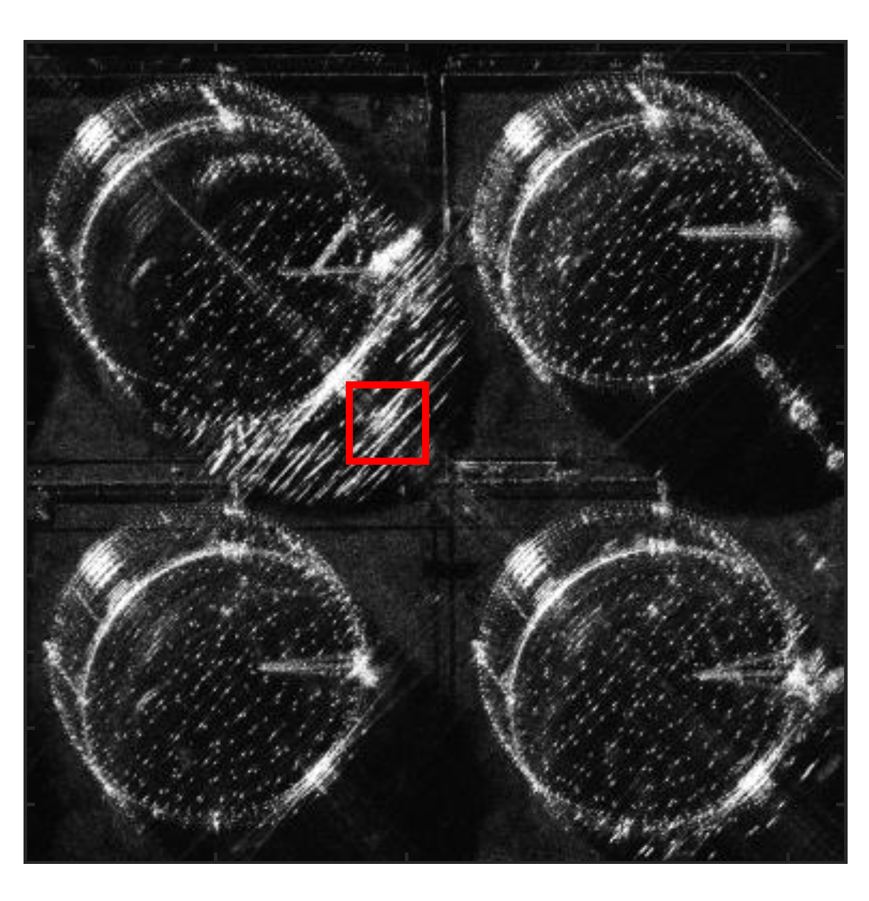
In order to quantitatively verify the performance of this algorithm, image intensity [31] is used to evaluate this method. The approximate location of the multipath ghost image can be known from the original images, and a part of the multipath area can be selected for analysis. Taking one of the sub-images as an example, as shown in Figure 22, the area outlined by the red frame is the selected area. The size of the selected area is 200 × 200 (azimuth × range). Correspondingly, there are Q = 200   ×   200 pixels in the selected area. The images are 8-bit images. Since the energy of the multipath signal is strong, the amplitude value of the multipath ghost image pixel is significantly higher than that of other pixels, and as the multipath signal is eliminated, the image intensity in the selected area will definitely decrease significantly. Then, the image intensity of the selected area can be used as an evaluation index for multipath signal suppression. The lower the image intensity in the selected area, the better the effect of suppressing multipath signals.
The image intensity is calculated as follows:
I = i = 1 Q A i 2
where there are Q   pixels in the selected area and A i represents the amplitude value of the i -th pixel.
Table 2 shows the image intensity of the selected area obtained after processing oil tank data with different methods. Upon processing the image using the method proposed in this paper, the image intensity achieved is the lowest, suggesting that the multipath suppression effect of the processed image is optimal.
Experiments indicate that the RPCA method has the best suppression effect on multipath ghost images in the multipath ghost image suppression of multi-aspect oil tank images. This method performs low-rank and sparse decomposition on the matrix composed of sequence images, and it can effectively suppress multipath ghost images while retaining the target signal. The PCA method can detect multipath pixels, but it causes target energy loss and multipath suppression signals remain because of its orthogonal decomposition principle. The sub-aperture fusion method can enhance the target energy and suppress the ghost image energy, but it cannot accurately identify the multipath ghost image and the real target and may cause the target energy in the weak scattering area to be lost.

5. Conclusions

To solve the problem of SAR multipath effects on complex structural targets like oil tanks, this paper analyzes the multi-aspect signal characteristics of multipath ghost images. The image features of the real targets remain stable across different aspects, whereas that of the multipath ghost images vary with aspects. According to this principle, a new multipath ghost image suppression method through multi-aspect observation is proposed. This method acquires image sequences at different aspect angles and separates stable target images from multipath ghost images through matrix decomposition. This paper compares the PCA-based method and RPCA-based method to illustrate the limitations of PCA and the advantages of RPCA. PCA is unable to separate the target image and multipath ghost image effectively because it uses orthogonal decomposition. In contrast, RPCA utilizes low-rank and sparse decomposition to separate real target images with low-rank characteristics from multipath ghost images with sparse characteristics. RPCA can effectively suppress the multipath ghost image while retaining the target signal. Finally, the method proposed in this paper is verified by the real airborne SAR data of the oil tank. A comparison is conducted among the RPCA method, PCA method, and the existing sub-aperture fusion method. The data processing results show that the RPCA method exhibits a superior multipath ghost image suppression effect.

Author Contributions

Conceptualization, Y.L. (Yun Lin); methodology, Y.L. (Yun Lin) and Z.T.; software, Y.L. (Yun Lin) and Z.T.; validation, Y.L. (Yun Lin) and Z.T.; formal analysis, Y.L. (Yun Lin) and Z.T.; resources, W.S., Y.L. (Yang Li) and Z.B.; writing—original draft Y.L. (Yun Lin) and Z.T.; writing—review and editing, Y.L. (Yun Lin), Z.T., Y.W., Y.L. (Yang Li), W.S. and Z.B.; supervision, Y.L. (Yun Lin); project administration, Y.W.; funding acquisition, Y.L. (Yun Lin) and Y.W. All authors have read and agreed to the published version of the manuscript.

Funding

This research was funded by the National Natural Science Foundation of China, grant numbers 62131001 and 62371005; and the Innovation Team Building Support Program of the Beijing Municipal Education Commission, grant number IDHT20190501.

Data Availability Statement

The data presented in this study are available on request from the corresponding author. The data are not publicly available due to privacy.

Acknowledgments

We thank the anonymous reviewers for their good advice.

Conflicts of Interest

The authors declare no conflicts of interest.

References

  1. Wu, Y. Multi-dimensional synthetic aperture radar imaging concept. J. Radars 2013, 2, 135–142. [Google Scholar] [CrossRef]
  2. Bao, Z.; Xing, M.; Wang, T. Radar Imaging Technology, 3rd ed.; Electronic Industry Press: Beijing, China, 2005; pp. 1–6. ISBN 9787121010729. [Google Scholar]
  3. Gloaguen, R.; Ghamisi, P.; Lorenz, S.; Kirsch, M.; Zimmermann, R.; Booysen, R.; Andreani, L.; Jackisch, R.; Hermann, E.; Tusa, L.; et al. The Need for Multi-Source, Multi-Scale Hyperspectral Imaging to Boost Non-Invasive Mineral Exploration. In Proceedings of the IGARSS 2018—2018 IEEE International Geoscience and Remote Sensing Symposium, Valencia, Spain, 22–27 July 2018; pp. 7430–7433. [Google Scholar]
  4. Zhang, Z.; Yuan, Z.; Wang, Y. Ground-based Interferometry Synthetic Aperture Radar and Applications in Deformation Monitoring. Beijing Surv. Mapp. 2020, 34, 27–32. [Google Scholar] [CrossRef]
  5. Miao, H. Assessment of Seismic Damage of Building Based on Full Polarimetric Image. Master’s Thesis, Institute of Earthquake Science, China Earthquake Administration, Beijing, China, 2020. [Google Scholar] [CrossRef]
  6. Marghany, M. Advanced Algorithms for Mineral and Hydrocarbon Exploration Using Synthetic Aperture Radar, 1st ed.; Elsevier: Amsterdam, The Netherlands, 2021; ISBN 9780128217962. [Google Scholar]
  7. Zhao, J.; Lou, C.; Li, J.; Yang, Z. Scattering characteristics and measurement method of a square cavity. J. Beijing Univ. Aeronaut. Astronaut. 2022, 48, 2415–2424. [Google Scholar] [CrossRef]
  8. Li, J.; Wang, X.; Wang, W. A New Shooting and Bouncing Rays Algorithm Based on Unigraphics and Its Application in Cavity Targets. In Proceedings of the 2017 International Applied Computational Electromagnetics Society Symposium (ACES), Suzhou, China, 1–4 August 2017; pp. 1–2. [Google Scholar]
  9. Zhang, Y.; Ding, C.; Wang, H.; Hu, D. A New Algorithm for Analyzing the SAR Image of the Cylindrical Oil Tank. J. Radars 2012, 1, 190–195. [Google Scholar] [CrossRef]
  10. Zhang, Y.; Chen, H.; Ding, C.; Wang, H. The multi-path scattering characteristics and the geometry extraction of cylinder tanks in SAR image. J. Infrared Millim. Waves 2012, 31, 379–384. [Google Scholar] [CrossRef]
  11. Zhang, Y.; Li, F.; Qiu, X.; Ding, C. An Approach for Simulating SAR Images of Tanks by Using Shooting and Bouncing Rays. In Proceedings of the 2015 IEEE 5th Asia-Pacific Conference on Synthetic Aperture Radar (APSAR), Singapore, 1–4 September 2015; pp. 474–476. [Google Scholar]
  12. Hammer, H.; Kuny, S.; Schulz, K. Simulation-Based Signature Analysis of Fuel Storage Tanks in High-Resolution SAR Images. IEEE Geosci. Remote Sens. Lett. 2017, 14, 1278–1282. [Google Scholar] [CrossRef]
  13. Villamil Lopez, C.; Stilla, U. Monitoring of Oil Tank Filling with Spaceborne SAR Using Coherent Scatterers. IEEE J. Sel. Top. Appl. Earth Obs. Remote Sens. 2021, 14, 5638–5655. [Google Scholar] [CrossRef]
  14. Xu, H.; Chen, W.; Sun, B.; Chen, Y.; Li, C. Oil tank detection in synthetic aperture radar images based on quasi-circular shadow and highlighting arcs. J. Appl. Remote Sens. 2014, 8, 083689. [Google Scholar] [CrossRef]
  15. Setlur, P.; Amin, M.; Ahmad, F. Multipath Model and Exploitation in Through-the-Wall and Urban Radar Sensing. IEEE Trans. Geosci. Remote Sens. 2011, 49, 4021–4034. [Google Scholar] [CrossRef]
  16. Setlur, P.; Alli, G.; Nuzzo, L. Multipath Exploitation in Through-Wall Radar Imaging Via Point Spread Functions. IEEE Trans. Image Process. 2013, 22, 4571–4586. [Google Scholar] [CrossRef] [PubMed]
  17. Zhou, H.; He, Y.; Duan, R.; Wang, Y. Virtual multi-view imaging based on through-the-wall radar. Chin. J. Radio Sci. 2015, 30, 333–338. [Google Scholar] [CrossRef]
  18. He, Y. The Research on Virtual Multi-Views through-the-Wall Radar Imaging. Master’s Thesis, Nanchang University, Nanchang, China, 2016. [Google Scholar]
  19. Wang, L.; Huang, X.; Zhou, Z.; Song, Q. Research on UWB SAR Image Formation with Suppressing Multipath Ghosts. In Proceedings of the 2006 CIE International Conference on Radar, Shanghai, China, 16–19 October 2006; pp. 1–3. [Google Scholar]
  20. Tan, Q.; Song, Y. A New Method for Multipath Interference Suppression in Through-the-Wall UWB Radar Imaging. In Proceedings of the 2010 2nd International Conference on Advanced Computer Control, Shenyang, China, 27–29 March 2010; IEEE: Shenyang, China, 2010; pp. 535–540. [Google Scholar]
  21. Tan, Q.; Leung, H.; Song, Y.; Wang, T. Multipath Ghost Suppression for Through-the-Wall Radar. IEEE Trans. Aerosp. Electron. Syst. 2014, 50, 2284–2292. [Google Scholar] [CrossRef]
  22. Li, Z.; Kong, L.; Jia, Y.; Zhao, Z.; Lan, F. A Novel Approach of Multi-Path Suppression Based on Sub-Aperture Imaging in through-Wall-Radar Imaging. In Proceedings of the 2013 IEEE Radar Conference (RadarCon13), Ottawa, ON, Canada, 29 April–3 May 2013; IEEE: Ottawa, ON, Canada, 2013; pp. 1–4. [Google Scholar]
  23. Shen, W.; Jin, L.; Liu, Q. Indoor multipath mechanism analysis and suppression method of through-wall radar. Radar Sci. Technol. 2016, 14, 605–613. [Google Scholar]
  24. Leigsnering, M.; Ahmad, F.; Amin, M.G.; Zoubir, A.M. Compressive Sensing Based Specular Multipath Exploitation for Through-the-Wall Radar Imaging. In Proceedings of the 2013 IEEE International Conference on Acoustics, Speech and Signal Processing, Vancouver, BC, Canada, 26–31 May 2013; IEEE: Vancouver, BC, Canada, 2013; pp. 6004–6008. [Google Scholar]
  25. Liu, L.; Jia, Z.; Yang, J.; Kasabov, N. SAR image change detection using double difference images and PCA algorithm. Comput. Eng. Des. 2019, 40, 2002–2006. [Google Scholar] [CrossRef]
  26. Huang, F.; Zheng, L.; Yang, C.; Liu, Z.; Deng, X.; Fu, M. SVD Clutter Suppression Method Based on K-Means Clustering. Radar Sci. Technol. 2020, 18, 611–617. [Google Scholar]
  27. Fang, J.; Hu, S.; Ma, X. SAR Image De-Noising via Grouping-Based PCA and Guided Filter. J. Syst. Eng. Electron. 2021, 32, 81–91. [Google Scholar] [CrossRef]
  28. Ahn, H.; Kang, M. Dynamic background subtraction with masked RPCA. Signal Image Video Process. 2020, 11, 407–414. [Google Scholar] [CrossRef]
  29. Han, Y.; Liu, L.; Wang, B.; Xu, H.; Li, J. Clutter Removal Using Robust Principal Component Analysis for Chaos Through-Wall Imaging Radar. Chin. J. Electron Devices 2020, 43, 142–146. [Google Scholar]
  30. Lin, Y.; Zhang, L.; Wei, L.; Zhang, H.; Feng, S.; Wang, Y.; Hong, W. Research on full-aspect three-dimensional SAR imaging method for complex structural facilities without prior model. J. Radars 2022, 11, 909–919. [Google Scholar] [CrossRef]
  31. Wang, M.; Li, W.; Ma, J.; Li, X. Clutter suppression algorithm based on pixel vector elimination in through-the-wall radar. Syst. Eng. Electron. 2022, 44, 827–833. [Google Scholar] [CrossRef]
Figure 1. Observation geometry.
Remotesensing 16 00637 g001
Figure 2. Image of external floating roof oil tank: (a) structure diagram of external floating roof oil tank; (b) external floating roof oil tank Google optical diagram; (c) airborne SAR observation geometry; (d) sub-aperture diagram of external floating roof oil tank collected by airborne SAR.
Remotesensing 16 00637 g002
Figure 3. The reflection between the outer wall of the oil tank and the maintenance walkway. (a) Radar signal propagation path; (b) SAR image of oil tank.
Remotesensing 16 00637 g003
Figure 4. The reflection between the outer wall of the oil tank and the ground. (a) Radar signal propagation path; (b) SAR image of oil tank.
Remotesensing 16 00637 g004
Figure 5. Reflection of outer wall of oil tank. (a) Radar signal propagation path; (b) SAR image of oil tank.
Remotesensing 16 00637 g005
Figure 6. Reflection between inner wall of oil tank and floating roof. (a) Radar signal propagation path; (b) SAR image of oil tank.
Remotesensing 16 00637 g006
Figure 7. Reflection between the floating roof and the vent valves on the floating roof. (a) Radar signal propagation path; (b) SAR image of oil tank.
Remotesensing 16 00637 g007
Figure 8. Multipath reflection between inner wall of oil tank and the floating roof. (a) Radar signal propagation path; (b) SAR image of oil tank.
Remotesensing 16 00637 g008
Figure 9. The schematic diagram of radar signal incident direction.
Remotesensing 16 00637 g009
Figure 10. The propagation path and imaging characteristics of radar signal in angle 1 observation. (a) Radar signal propagation path; (b) SAR image of oil tank.
Remotesensing 16 00637 g010
Figure 11. The propagation path and imaging characteristics of radar signal in angle 2 observation. (a) Radar signal propagation path; (b) SAR image of oil tank.
Remotesensing 16 00637 g011
Figure 12. The propagation path and imaging characteristics of radar signal in angle 3 observation. (a) Radar signal propagation path; (b) SAR image of oil tank.
Remotesensing 16 00637 g012
Figure 13. The principle of PCA.
Remotesensing 16 00637 g013
Figure 14. The schematic diagram of PCA decomposition. (a) The original sequence; (b) the ideal sequence; (c) the sequence after PCA decomposition.
Remotesensing 16 00637 g014
Figure 15. The schematic diagram of RPCA decomposition. (a) The low-rank part of RPCA decomposition; (b) the sparse part of RPCA decomposition.
Remotesensing 16 00637 g015
Figure 16. Multipath ghost suppression method based on RPCA.
Remotesensing 16 00637 g016
Figure 17. The results of PCA decomposition of three sub-images. (a) Three sub-images; (b) the component of the stable principal component direction of PCA decomposition; (c) unstable components of PCA decomposition.
Remotesensing 16 00637 g017
Figure 18. The results of RPCA decomposition of three sub-images. (a) Three sub-images; (b) the low-rank part of RPCA decomposition; (c) the sparse part of RPCA decomposition.
Remotesensing 16 00637 g018
Figure 19. The final fused image is obtained by summing the decomposed sequence images: (a) the component of the stable principal component direction of PCA decomposition; (b) unstable components of PCA decomposition; (c) the low-rank part of RPCA decomposition; (d) the sparse part of RPCA decomposition.
Remotesensing 16 00637 g019
Figure 20. The final fusion image obtained after processing by RPCA method in this article.
Remotesensing 16 00637 g020
Figure 21. The result images after processing through the sub-aperture image fusion method. (a) The result image after adding and multiplying fusion; (b) the result image after double-layer fusion.
Remotesensing 16 00637 g021
Figure 22. The selected area.
Remotesensing 16 00637 g022
Table 1. Parameter list.
Experimental ParametersValue
Center frequency10 GHz
Bandwidth1 GHz
Observation azimuth ±44°
Sub-aperture synthetic aperture angle
Incident angle45°
Flight height7 km
Table 2. Comparison of image intensity after data processing using different methods.
Processing MethodImage Intensity
PCA 3.1492 × 10 8
Sub-aperture multiplication and addition fusion 7.4637 × 10 8
Sub-aperture double-layer fusion 4.1492 × 10 8
RPCA 6.7992 × 10 7
Disclaimer/Publisher’s Note: The statements, opinions and data contained in all publications are solely those of the individual author(s) and contributor(s) and not of MDPI and/or the editor(s). MDPI and/or the editor(s) disclaim responsibility for any injury to people or property resulting from any ideas, methods, instructions or products referred to in the content.

